1
1500-RPK
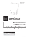
Raypak B6000 Metasys™ N2
System Protocol Interface
Raypak Burner Controller
User Manual
March 15, 2005
Please Read This Notice
Successful application of this module requires a reasonable working knowledge of the Raypak
B6000 Metasys™ N2 System Protocol Interface Raypak Burner Controller hardware and the
application in which the combination is to be used. For this reason, it is important that those
responsible for implementation satisfy themselves that the combination will meet the needs of the
application without exposing personnel or equipment to unsafe or inappropriate working conditions.
This manual is provided to assist the user. Every attempt has been made to assure that the
information provided is accurate and a true reflection of the product's installation requirements. In
order to assure a complete understanding of the operation of the product, the user should read all
applicable documentation on the operation of the hardware.
Under no conditions will ProSoft Technology, Inc. be responsible or liable for indirect or
consequential damages resulting from the use or application of the product.
Reproduction of the contents of this manual, in whole or in part, without written permission from
ProSoft Technology, Inc. is prohibited.
Information in this manual is subject to change without notice and does not represent a
commitment on the part of ProSoft Technology, Inc. Improvements and/or changes in this manual
or the product may be made at any time. These changes will be made periodically to correct
technical inaccuracies or typographical errors.
IMPORTANT: The 1500 card will allow remote access to commands in the
B6000 Controller. The User is responsible for assuring that any applicable
regulations concerning the remote operation of equipment are adhered to.
Metasys and Companion are trademarks of Johnson Controls, Inc.
Your Feedback Please
We always want you to feel that you made the right decision to use our products. If you have
suggestions, comments, compliments or complaints about the product, documentation or support,
please write or call us.
ProSoft Technology, Inc.
1675 Chester Avenue, Second Floor
Bakersfield, CA 93301
(661) 716-5100
(661) 716-5101 (Fax)
http://www.prosoft-technology.com
Copyright © ProSoft Technology, Inc. 2000 - 2005. All Rights Reserved.
1500-RPK User Manual
March 15, 2005
Contents
1500-RPK ♦ Raypak Burner Controller
Contents
PLEASE READ THIS NOTICE...........................................................................................................2
Your Feedback Please ..................................................................................................................2
1
2
PRODUCT SPECIFICATIONS....................................................................................................5
1.1
Metasys N2 Slave Interface............................................................................................5
1.2
Raypak B6000 Interface..................................................................................................6
1.3
General Specifications ...................................................................................................6
1.4
Hardware Specifications ................................................................................................6
METASYS SLAVE PORT FUNCTIONALITY .............................................................................7
2.1
2.1.1
Command/Reply Cycle..................................................................................................7
2.1.2
N2 System Protocol Commands ...................................................................................7
2.1.3
Command Error Checking.............................................................................................9
2.1.4
Data Integrity .................................................................................................................9
2.2
3
N2 Point Layout...............................................................................................................9
HARDWARE SETUP.................................................................................................................11
3.1
1500 Card Setup ............................................................................................................11
3.1.1
Connecting Power to the 1500 Card ...........................................................................11
3.1.2
Dip Switch Configuration .............................................................................................11
3.1.3
1500 Jumper Configurations .......................................................................................12
3.2
4
N2 Slave Communications.............................................................................................7
B6000 Communications ...............................................................................................13
N2 SYSTEM PROTOCOL SUPPORT.......................................................................................15
4.1
Attribute Commands ....................................................................................................15
4.1.1
Analog Input ................................................................................................................15
4.1.2
Binary Input .................................................................................................................15
4.1.3
Analog Output..............................................................................................................16
4.1.4
Binary Output...............................................................................................................16
ProSoft Technology, Inc.
March 22, 2005
Page 3 of 32
1500-RPK ♦ Raypak Burner Controller
5
Contents
4.2
Control Commands ...................................................................................................... 16
4.3
Device Identifier Code.................................................................................................. 16
DIAGNOSTICS ......................................................................................................................... 17
5.1
LED Indicators .............................................................................................................. 17
APPENDIX A - METASYS POINT MAPPING ................................................................................. 19
Raypak Metasys Register Assignements................................................................................. 19
Raypak Metasys Register Assignements................................................................................. 20
APPENDIX B - COMMUNICATION CABLE CONNECTION DIAGRAMS ..................................... 25
PORT 1 - N2 System Protocol Slave Communication Port..................................................... 25
RS-485 CABLE CONFIGURATION .......................................................................................... 25
PORT 2 - Raypak B6000 Controller Communication Port ...................................................... 25
RS-485 CABLE CONFIGURATION .......................................................................................... 25
SUPPORT, SERVICE & WARRANTY............................................................................................. 27
Module Service and Repair ........................................................................................................ 27
General Warranty Policy ............................................................................................................ 28
Limitation of Liability.................................................................................................................. 28
Hardware Product Warranty Details ......................................................................................... 29
INDEX............................................................................................................................................... 31
Page 4 of 32
ProSoft Technology, Inc.
March 22, 2005
Product Specifications
1
1500-RPK ♦ Raypak Burner Controller
Product Specifications
In This Chapter
¾
Metasys N2 Slave Interface ..................................................... 5
¾
Raypak B6000 Interface........................................................... 6
¾
General Specifications ............................................................. 6
¾
Hardware Specifications .......................................................... 6
The ProSoft Technology, Inc. 1500-RPK card is a hardware product designed to
be a communications front end for the Raypak B6000 Burner Controller and
Johnson Controls N2 compatible masters.
The product includes the following functionality:
1.1
Metasys N2 Slave Interface
Binary Input, Binary Output, Analog Input and Analog Output data type
commands supported for primary control/monitoring of the B6000 operating
parameters
Supported Command/Subcommands:
0/4 :
Poll Message No Acknowledge
0/5 :
Poll Message with Acknowledge
0/9 :
Status Update
1/1 :
Read Analog Input Attributes
1/2 :
Read Binary Input Attributes
1/3 :
Read Analog Output Attributes
1/4 :
Read Binary Output Attributes
2/1 :
Write Analog Input Attributes
2/2 :
Write Binary Input Attributes
2/3 :
Write Analog Output Attributes
2/4 :
Write Binary Output Attributes
7/2/3:
Override Analog Output
7/2/4:
Override Binary Output
ProSoft Technology, Inc.
March 22, 2005
Page 5 of 32
1500-RPK ♦ Raypak Burner Controller
F
:
Product Specifications
Identify Device Type
The following commands are recognized, and acknowledged, but do not have
impact on the operation of the 1500-N2, and do not return any data:
0/0 :
Time Update
0/8 :
Warm Start
All other commands return a Bad Command Error Code
1.2
1.3
Warning and Alarming functions performed on Analog Input and Binary Input
data types
Change Of State Response buffering
Raypak B6000 Interface
RS-485 electrical interface (as well as RS-232 and RS-422)
Emulates Raypak Modem address and functionality
General Specifications
Configuration via dip switches
Slave Address, Baud and Parity
1.4
Hardware Specifications
4"x5" form factor
Two male 9-pin D shell connectors
Slave communications port configurable for RS-232C or RS-422/485
Communication status lights - Active and Fault for each port
9 to 30 VDC external power
Page 6 of 32
ProSoft Technology, Inc.
March 22, 2005
Metasys Slave Port Functionality
2
1500-RPK ♦ Raypak Burner Controller
Metasys Slave Port Functionality
In This Chapter
2.1
¾
N2 Slave Communications ....................................................... 7
¾
N2 Point Layout........................................................................ 9
N2 Slave Communications
The ProSoft 1500 card supports the Johnson Controls Metasys™ N2 Protocol,
as a slave, on port 1. This capability allows the module to communicate data
from the Raypak B6000 Burner Controller to a Johnson Controls Metasys Master
such as the Johnson Controls Companion™ or Metasys software.
The following discusses the functional capabilities of the card.
2.1.1
Command/Reply Cycle
Successful communications between a Slave and a Master will always consist of
the following two transactions:
Signal
Description
Command:
Message from master giving instruction to slave.
Reply:
Response to command.
A slave station will respond to a master issued command in several ways.
Signal
Description
Data Message:
If the command was executed by the slave, the response message will
include the data requested, or an acknowledgment that the command
was executed.
Error Message:
If the command could not be executed by the slave, for whatever
reason, an error response message is transmitted to the master. The
error response message contains an error code indicating the cause of
the error.
No Reply:
If the master does not detect a reply within its timeout period, the
master should re-transmit the command, before a time out error is
issued. If the Slave could not decode the message or an error
occurred preventing the Slave from recognizing the message, no
response will be issued.
2.1.2
N2 System Protocol Commands
The 1500 supports the commands and the data types necessary to enable
control of the B6000 Controller from an N2 master. The data types and the
commands, as well as the associated addressable points are discussed below.
ProSoft Technology, Inc.
March 22, 2005
Page 7 of 32
1500-RPK ♦ Raypak Burner Controller
Metasys Slave Port Functionality
Data Types
The N2 System protocol treats data as objects, with each data type having a
different structure and purpose. The data types recognized by the 1500 card are
as follows:
Binary Input
Binary Output
Analog Input
Analog Output
Reading Attributes
The data objects contain attributes which describe several a data point, and
some of its functionality. The contents of these attributes, including object
configuration, status, current value, and alarm/warning limits, can be accessed
with the following commands:
1/1
Read Analog Input Attributes
1/2
Read Binary Input Attributes
1/3
Read Analog Output Attributes
1/4
Read Binary Output Attributes
Writing Attributes
The data object attributes can be configured by a master using the following
commands:
2/1
Write Analog Input Attributes
2/2
Write Binary Input Attributes
2/3
Write Analog Output Attributes
2/4
Write Binary Output Attributes
Controlling the B6000 Controller
Access to the control functions is made available through the Override
commands. The following commands allow the B6000 to be controlled:
7/2/3
Override Analog Output
7/2/4
Override Binary Output
Page 8 of 32
ProSoft Technology, Inc.
March 22, 2005
Metasys Slave Port Functionality
1500-RPK ♦ Raypak Burner Controller
Status Update
The host can issue a 'Status Update' command to the 1500. The response will
contain device information ("1500-N2 Rev 1.0A") as well as current status
information.
0/9
Status Update
Identify Device
When a master host first powers up, the 'Identify Device' command is issued to
all of the slaves. In the case of the 1500 card, the Device Code 10 Hex is
returned to the host. When the 1500 first powers up, it will return and error code
0 in response to all commands from the host, indicating to the host that a power
up condition has occurred. The host will respond with the "Identify Device"
command, telling the 1500 that the host has detected the power condition. The
command code is:
F
2.1.3
Identify Device
Command Error Checking
When the Slave cannot execute a command, an error code is generated and
returned to the Master. Error codes generated at the Slave will usually be
indicative of an illegal function, an illegal address, or bad data.
2.1.4
Data Integrity
As in all good protocols, there must exist a level of data integrity checking to
verify, with some degree of assurance, the quality of the transmitted data. The
N2 System protocol supports a summation/modulus type of error checking on the
address and data content of the communication packet.
2.2
N2 Point Layout
A relationship between the N2 Point Address and the B6000 parameters has
been set up to ease control and monitoring of the unit. The relationship, by data
object type, is shown in detail in Appendix A.
ProSoft Technology, Inc.
March 22, 2005
Page 9 of 32
1500-RPK ♦ Raypak Burner Controller
Page 10 of 32
Metasys Slave Port Functionality
ProSoft Technology, Inc.
March 22, 2005
Hardware Setup
3
1500-RPK ♦ Raypak Burner Controller
Hardware Setup
In This Chapter
3.1
¾
1500 Card Setup .................................................................... 11
¾
B6000 Communications ......................................................... 13
1500 Card Setup
3.1.1
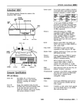
Connecting Power to the 1500 Card
The 1500 Card requires an external source of DC voltage. The DC source
voltage should be between 9V and 30V. The power is connected to TB1, located
near the two 9 pin serial port connections.
The connection to TB1 is as follows:
TB1-1 9-30 VDC
TB1-2 Common
3.1.2
Dip Switch Configuration
The 1500 card is configured primarily through two sets of dip switches. These
switches are read initially on power up only. The function of the dip switches is as
follows (a value of one (1) is registered when the a switch is in the ON position):
SW 1 : Metasys Port Configuration
Switch
Function
Position
1
Baud Rate - 1|For Metasys N2 Systems:
1 = On
2
Baud Rate - 2 |
2 = Off
3
Baud Rate - 4|
3 = On
|
Configures N2 port for 9600 baud
4
Parity - 1|For Metasys N2 Systems:
4 = Off
5
Parity - 2|
5 = Off
|
Configures N2 port for No Parity
6
Not Used
7
Not Used
8
Not Used
ProSoft Technology, Inc.
March 22, 2005
Page 11 of 32
1500-RPK ♦ Raypak Burner Controller
Hardware Setup
SW 2 : Metasys N2 Slave Address
Switch
Function
Position
1
Address Bit 0| Value = 1
Example:
2
Address Bit 1| Value = 2
Address 12
3
Address Bit 2| Value = 4
Bits 8 7 6 5 4 3 2 1
4
Address Bit 3 | Value = 8
00001100
5
Address Bit 4| Value = 16
6
Address Bit 5| Value = 32
7
Address Bit 6| Value = 64
8
Address Bit 7| Value = 128
The parameters are defined as follows:
Metasys N2 Slave Address:
Each of the separate drops off of a Johnson Controls Metasys host must have a
different slave address. The slave address is selected by encoding the slave
address in a binary form using the dip switches.
3.1.3
1500 Jumper Configurations
The 1500 card has five sets of jumpers on the board. Generally, the default
jumper positions will be adequate for most applications, with JP4 and JP5 being
the only jumpers that should ever need to be reviewed. For completeness, we
provide the following discussion on all of the jumper locations:
JP
Discussion
1
Hardware Reset (Not used)
2
Raypak Port Power (P2)
1-2 Non-Isolated (Default)
2-3 Isolated (Should not be used)
3
Raypak Port Ground (P2)
1-2 Non-isolated (Default)
2-3 Isolated (Should not be used)
4
Metasys Port (P1) Termination Resistor
1-2 Connect 120 Ohms across Rec lines
2-3 Disconnect 120 Ohms
5
Metasys Port (P1) RS-232 or RS-422/485 Select
1-2 RS-232 Select (Should not be used)
2-3 RS-422/485 Select (Default)
Page 12 of 32
ProSoft Technology, Inc.
March 22, 2005
Hardware Setup
3.2
1500-RPK ♦ Raypak Burner Controller
B6000 Communications
The B6000 communications interface has been hard coded to operate at the
following default conditions:
Baud
9600
Parity
Odd
Stop Bits
1
The 1500 card emulates the modem card that is regularly connected to the
B6000 Controller. This is important as when the 1500 card is connected to the
B6000, the modem card cannot be connected simultaneously.
Default Baud Rates and Parity for all supported devices are different. Be sure
to verify unit configurations.
ProSoft Technology, Inc.
March 22, 2005
Page 13 of 32
1500-RPK ♦ Raypak Burner Controller
Page 14 of 32
Hardware Setup
ProSoft Technology, Inc.
March 22, 2005
N2 System Protocol Support
4
1500-RPK ♦ Raypak Burner Controller
N2 System Protocol Support
In This Chapter
¾
Attribute Commands .............................................................. 15
¾
Control Commands ................................................................ 16
¾
Device Identifier Code............................................................ 16
The ProSoft Technology 1500 card supports several data read and write
commands for the N2 System protocol. The decision on which command to use
is made depending on the type of data being addressed, and the level of protocol
support in the master equipment. The following sections detail the different
commands supported by the module.
4.1
Attribute Commands
The 1500 card supports the reading and writing to the data object attributes.
Although read/write support is available for all attributes (i.e., the card will accept,
store, and respond with values downloaded from a master), the 1500 does not
use all aspects of the attribute functions. The following subsections discuss each
data type, and in particular any functional aspects not supported by the 1500.
4.1.1
Analog Input
The Analog Input data object is by far the most complicated of the objects. All
aspects of warning and alarm logic are supported by the 1500 ( i.e., the 1500
uses the low and high alarm/warning limits to detect and trigger the object's
alarm bits).
Not supported however are the linear ranging parameters, the filter weight, and
the offset. The presumption is made that all analog input values gathered from
the B6000 will come in scaled. No scaling parameters are required from the
master to support any of the analog input values.
4.1.2
Binary Input
(02): Read Input Status
The Binary Input data object supports the normal state and alarm logic. The
debounce and accumulator attributes are not supported.
ProSoft Technology, Inc.
March 22, 2005
Page 15 of 32
1500-RPK ♦ Raypak Burner Controller
4.1.3
N2 System Protocol Support
Analog Output
The Analog Output data object is used by the 1500 as a simple conduit for
setpoints in the B6000. No support is provided for scaling the output value, or for
verifying the saturation level of the output value. The value written from the
master is communicated to the Controller.
4.1.4
Binary Output
The Binary Output data object is implemented to respond directly to the
commands received from the master. When the master sends an output
command, either a bit set or reset, the command is decoded and communicated
to the Controller.
4.2
Control Commands
The 1500 card accepts control commands from a master upon receipt of the
following commands:
4.3
Override Analog Output (Command 7/2/3)
Override Binary Output (Command 7/2/4)
Device Identifier Code
When the 1500 receives an Identify Yourself command, the code 10 Hex is sent
to the master. The 10 Hex is the device ID used by non-Johnson Controls
hardware.
Page 16 of 32
ProSoft Technology, Inc.
March 22, 2005
Diagnostics
5
1500-RPK ♦ Raypak Burner Controller
Diagnostics
In This Chapter
¾
LED Indicators........................................................................ 17
Several hardware diagnostics capabilities have been implemented using the LED
indicator lights on the front of the 1500 card. The possible conditions as indicated
by the lights are:
5.1
LED Indicators
Several hardware diagnostics capabilities have been implemented using the LED
indicator lights on the front of the module. The possible conditions as indicated
by the lights are:
NAME
LED
Color
Status
Indication
N2 (P1)
D1
Green
Blinking
The 1500 is receiving a valid
response from the Metasys Host
Off
The 1500 is not detecting a valid
command. If the master is
transmitting, be sure all dip switches
are set correctly.
Blinking
The 1500 is processing a B6000
command
OFF
Check cable connections
ON
The Metasys port has detected a
communications error condition
OFF
No error conditions at this time.
ON
The 1500 card has detected a
communications error condition.
OFF
No error conditions at this time.
ACTIVE
Raypak (P2)
D2
Green
D3
Red
ACTIVE
N2 (P1)
COMM
ERR
Raypak (P2)
D4
Red
FAULT
Should the configuration dip switches select an invalid address or an invalid
baud rate, the LED indicators will alternate in an on/off fashion on 1/2 second
intervals until correct values are selected.
ProSoft Technology, Inc.
March 22, 2005
Page 17 of 32
1500-RPK ♦ Raypak Burner Controller
Page 18 of 32
Diagnostics
ProSoft Technology, Inc.
March 22, 2005
APPENDIX A - Metasys Point Mapping
1500-RPK ♦ Raypak Burner Controller
APPENDIX A - Metasys Point Mapping
In This Chapter
¾
Raypak Metasys Register Assignements............................... 19
¾
Raypak Metasys Register Assignements............................... 20
Raypak Metasys Register Assignements
Analog
Output
Parm
Offset
Description
AO1
28
Setpoint
Day Setup (Desired water temp @ 70F)
AO2
29
Niteset
Night Setpoint (Desired water temp @
70F)
2
AO3
30
Ratio Out
1-200 = 0.1 – 20.0 in 0.1 increments
3
AO4
31
Throttling
Delta T of all boilers in
system
4
AO5
32
Modulating Step ( % )
5
AO6
33
Wait State Time (Sec)
6
Rise
Msg #1
1
AO7
34
Outdoor Cut off temperature
7
AO8
35
Contro Band (degrees F tolerance from TAR)
8
AO9
36
Lead Boiler Number (1 to Number of Boilers online)
9
AO10
37
Number of Boilers on line
10
AO11
38
TP – Boiler Pump Delays (Min) Boiler #1
11
AO12
39
TP – Boiler Pump Delays (Min) Boiler #2
12
AO13
40
TP – Boiler Pump Delays (Min) Boiler #3
13
AO14
41
TP – Boiler Pump Delays (Min) Boiler #4
14
AO15
42
TP – Boiler Pump Delays (Min) Boiler #5
15
AO16
43
TP – Boiler Pump Delays (Min) Boiler #6
16
AO17
44
TP – Boiler Pump Delays (Min) Boiler #7
17
AO18
45
TP – Boiler Pump Delays (Min) Boiler #8
18
AO19
46
TS – Boiler Start Times (Sec) Boiler #1
19
AO20
47
TS – Boiler Start Times (Sec) Boiler #2
20
AO21
48
TS – Boiler Start Times (Sec) Boiler #3
21
AO22
49
TS – Boiler Start Times (Sec) Boiler #4
22
AO23
50
TS – Boiler Start Times (Sec) Boiler #5
23
AO24
51
TS – Boiler Start Times (Sec) Boiler #6
24
AO25
52
TS – Boiler Start Times (Sec) Boiler #7
25
AO26
53
TS – Boiler Start Times (Sec) Boiler #8
26
AO27
54
Time – Hrs
27
ProSoft Technology, Inc.
March 22, 2005
Page 19 of 32
1500-RPK ♦ Raypak Burner Controller
APPENDIX A - Metasys Point Mapping
Analog
Output
Parm
Offset
Description
AO28
55
Time – Min
28
AO29
56
Time – DWK
29
AO30
57
Lead Change
Hours
30
58
Night Setback
Binary
Output
Parm
Offset
Description
BI_1
0
Bit 0 = Night Setback present
59
Controller LED Status
BI_2
0
Bit 0 = Fault Status (1=system fault)
BI_3
1
Bit 1 = Call Out Request ( 1 = Yes)
Msg #2
1
2
Raypak Metasys Register Assignements
Analog
Input
Parm
Offset
Description
AI_1
60
Outdoor Temp + 35
3
AI_2
61
Indoor Temp + 35
4
AI_3
62
Controller Target Temp
5
AI_4
63
Valve Positions (0-100%) - Boiler #1
6
AI_5
64
Valve Positions (0-100%) - Boiler #2
7
AI_6
65
Valve Positions (0-100%) - Boiler #3
8
AI_7
66
Valve Positions (0-100%) - Boiler #4
9
AI_8
67
Valve Positions (0-100%) - Boiler #5
10
AI_9
68
Valve Positions (0-100%) - Boiler #6
11
AI_10
69
Valve Positions (0-100%) - Boiler #7
12
AI_11
70
Valve Positions (0-100%) - Boiler #8
13
BI_5_14
71
Boiler Status (0-10) - Boiler #1
BI_15_2
4
72
Boiler Status (0-10) - Boiler #2
2
BI_25_3
4
73
Boiler Status (0-10) - Boiler #3
3
BI_35_4
4
74
Boiler Status (0-10) - Boiler #4
4
BI_45_5
4
75
Boiler Status (0-10) - Boiler #5
5
BI_55_6
4
76
Boiler Status (0-10) - Boiler #6
6
BI_65_7
4
77
Boiler Status (0-10) - Boiler #7
7
BI_75_8
4
78
Boiler Status (0-10) - Boiler #8
8
Page 20 of 32
0x3d
1
ProSoft Technology, Inc.
March 22, 2005
APPENDIX A - Metasys Point Mapping
1500-RPK ♦ Raypak Burner Controller
Analog
Input
Parm
Offset
Description
AI_12
79
Setpoint
Day Setup (Desired water
temp)
9
AI_13
80
Niteset
Night Setpoint (Desired water temp)
10
AI_14
81
Ratio Out
1-200 = 0.1 - 20.0 in 0.1
incr.
11
AI_15
82
Throttling
Delta T of all boilers in
system
12
AI_16
83
Modulating Step ( % )
13
AI_17
84
Wait State Time (Sec)
14
AI_18
85
Outdoor Cut off temperature
15
AI_19
86
Contro Band (degrees F tolerance from TAR)
16
AI_20
87
Lead Boiler Number (1 to Number of Boilers online)
17
AI_21
88
Number of Boilers on line
AI_22
89
TP - Boiler Pump Delays (Min) Boiler #1
AI_23
90
TP - Boiler Pump Delays (Min) Boiler #2
2
AI_24
91
TP - Boiler Pump Delays (Min) Boiler #3
3
AI_25
92
TP - Boiler Pump Delays (Min) Boiler #4
4
AI_26
93
TP - Boiler Pump Delays (Min) Boiler #5
5
AI_27
94
TP - Boiler Pump Delays (Min) Boiler #6
6
AI_28
95
TP - Boiler Pump Delays (Min) Boiler #7
7
AI_29
96
TP - Boiler Pump Delays (Min) Boiler #8
8
AI_30
97
TS - Boiler Start Times (Sec) Boiler #1
9
AI_31
98
TS - Boiler Start Times (Sec) Boiler #2
10
AI_32
99
TS - Boiler Start Times (Sec) Boiler #3
11
AI_33
100
TS - Boiler Start Times (Sec) Boiler #4
12
AI_34
101
TS - Boiler Start Times (Sec) Boiler #5
13
AI_35
102
TS - Boiler Start Times (Sec) Boiler #6
14
AI_36
103
TS - Boiler Start Times (Sec) Boiler #7
15
AI_37
104
TS - Boiler Start Times (Sec) Boiler #8
16
AI_38
105
Time - Hrs
AI_39
106
Time - Min
AI_40
107
Time - DWK
AI_41
108
Lead Change
AI_42
109
Hrs Remaining
BI_4
110
Bit 0 = Setback on (1)
AI_43
111/112
Boiler Valve Up Times (Sec)
#1
AI_44
113/114
Boiler Valve Up Times (Sec)
#2
AI_45
115/116
Boiler Valve Up Times (Sec)
#3
AI_46
117/118
Boiler Valve Up Times (Sec)
#4
AI_47
119/120
Boiler Valve Up Times (Sec)
#5
AI_48
121/122
Boiler Valve Up Times (Sec)
#6
ProSoft Technology, Inc.
March 22, 2005
18
0x4f
1
Page 21 of 32
1500-RPK ♦ Raypak Burner Controller
APPENDIX A - Metasys Point Mapping
Analog
Input
Parm
Offset
Description
AI_49
123/124
Boiler Valve Up Times (Sec)
#7
AI_50
125/126
Boiler Valve Up Times (Sec)
#8
AI_51
127/128
Boiler Valve Down Times
(Sec)
#1
AI_52
129/130
Boiler Valve Down Times
(Sec)
#2
AI_53
131/132
Boiler Valve Down Times
(Sec)
#3
AI_54
133/134
Boiler Valve Down Times
(Sec)
#4
AI_55
135/136
Boiler Valve Down Times
(Sec)
#5
AI_56
137/138
Boiler Valve Down Times
(Sec)
#6
AI_57
139/140
Boiler Valve Down Times
(Sec)
#7
AI_58
141/142
Boiler Valve Down Times
(Sec)
#8
143
144
145
146
147
148
149
AI_59
150
OC Dead band: Off T>)C, ON T<=OCOCDB
4621h
AI_60
151
Wait1 : Wait State Time
4605h
AI_61
152
KPN : Porp Constant Numerator (0-255)
460bh
AI_62
152
KPD: Porp Constant Denominator (0-255)
460ch
AI_63
153
KDN : Diff Constant Numerator (0-255)
460fh
AI_64
154
KDD: Diff Constant Denominator (0-255)
4610h
155
Spare
156
Spare
157
Spare
158
Spare
159
Spare
AO31
160
OC Dead band: Off T>)C, ON T<=OCOCDB
4621h
AO32
161
Wait1 : Wait State Time
4605h
AO33
162
KPN : Porp Constant Numerator (0-255)
460bh
AO34
163
KPD: Porp Constant Denominator (0-255)
460ch
AO35
164
KDN : Diff Constant Numerator (0-255)
460fh
Page 22 of 32
extra read
registers
extra write
registers
ProSoft Technology, Inc.
March 22, 2005
APPENDIX A - Metasys Point Mapping
1500-RPK ♦ Raypak Burner Controller
Analog
Input
Parm
Offset
Description
AO36
165
KDD: Diff Constant Denominator (0-255)
Binary
Input
Parm
Offset
Description
BO_1
166
Initialize B6000 by writing STAR 80h 0dh
to unit
STAR
BO_2
167
Setback on/off control (0 = Off, 1 = On) Write word value to B6000
4025h
168
Spare
169
Spare
ProSoft Technology, Inc.
March 22, 2005
4610h
Page 23 of 32
1500-RPK ♦ Raypak Burner Controller
Page 24 of 32
APPENDIX A - Metasys Point Mapping
ProSoft Technology, Inc.
March 22, 2005
APPENDIX B - Communication Cable Connection Diagrams1500-RPK ♦ Raypak Burner Controller
APPENDIX B - Communication Cable Connection
Diagrams
In This Chapter
¾
PORT 1 - N2 System Protocol Slave Communication Port .... 25
¾
PORT 2 - Raypak B6000 Controller Communication Port...... 25
PORT 1 - N2 System Protocol Slave Communication Port
RS-485 CABLE CONFIGURATION
1500 Card
NCM
1
Tx_A
----------------
4
Rx_A
----|
6
Tx_B
----------------
9
Rx_B
----|
7
RTS
----
8
CTS
----
5
GND
----------------
N2 +
N2 -
|
N2 Ref
PORT 2 - Raypak B6000 Controller Communication Port
RS-485 CABLE CONFIGURATION
1500 Card
2
B6000
Rx_B
--------------------
9
Tx_B
---+
4
Tx_A
--------------------
(-) Blue w/ white stripe
|
(+) White w/ blue strip
|
6
Rx_A
---+
5
COM
--------------------
ProSoft Technology, Inc.
March 22, 2005
Orange w/ white stripe
Page 25 of 32
1500-RPK ♦ Raypak Burner ControllerAPPENDIX B - Communication Cable Connection Diagrams
Page 26 of 32
ProSoft Technology, Inc.
March 22, 2005
Support, Service & Warranty
1500-RPK ♦ Raypak Burner Controller
Support, Service & Warranty
ProSoft Technology, Inc. survives on its ability to provide meaningful support to
its customers. Should any questions or problems arise, please feel free to
contact us at:
Internet
Web Site: http://www.prosoft-technology.com/support
E-mail address: [email protected]
Phone
(661) 716-5100
(661) 716-5101 (Fax)
Postal Mail
ProSoft Technology, Inc.
1675 Chester Avenue, Second Floor
Bakersfield, CA 93301
Before calling for support, please prepare yourself for the call. In order to provide
the best and quickest support possible, we will most likely ask for the following
information (you may wish to fax it to us prior to calling):
Product Serial and Version Number
1500 Configuration Information
Dip Switches
Jumpers
Communication cabling
An after-hours answering system (on the Bakersfield number) allows pager
access to one of our qualified technical and/or application support engineers at
any time to answer the questions that are important to you.
Module Service and Repair
The 1500-RPK device is an electronic product, designed and manufactured to
function under somewhat adverse conditions. As with any product, through age,
misapplication, or any one of many possible problems the device may require
repair.
When purchased from ProSoft Technology, Inc., the device has a 1 year parts
and labor warranty according to the limits specified in the warranty. Replacement
and/or returns should be directed to the distributor from whom the product was
purchased. If you need to return the device for repair, obtain an RMA (Returned
Material Authorization) number from ProSoft Technology, Inc.. Please call the
factory for this number, and print the number prominently on the outside of the
shipping carton used to return the device.
ProSoft Technology, Inc.
March 22, 2005
Page 27 of 32
1500-RPK ♦ Raypak Burner Controller
Support, Service & Warranty
General Warranty Policy
ProSoft Technology, Inc. (Hereinafter referred to as ProSoft) warrants that the
Product shall conform to and perform in accordance with published technical
specifications and the accompanying written materials, and shall be free of
defects in materials and workmanship, for the period of time herein indicated,
such warranty period commencing upon receipt of the Product.
This warranty is limited to the repair and/or replacement, at ProSoft's election, of
defective or non-conforming Product, and ProSoft shall not be responsible for the
failure of the Product to perform specified functions, or any other nonconformance caused by or attributable to: (a) any misapplication or misuse of the
Product; (b) failure of Customer to adhere to any of ProSoft's specifications or
instructions; (c) neglect of, abuse of, or accident to, the Product; or (d) any
associated or complementary equipment or software not furnished by ProSoft.
Limited warranty service may be obtained by delivering the Product to ProSoft
and providing proof of purchase or receipt date. Customer agrees to insure the
Product or assume the risk of loss or damage in transit, to prepay shipping
charges to ProSoft, and to use the original shipping container or equivalent.
Contact ProSoft Customer Service for further information.
Limitation of Liability
EXCEPT AS EXPRESSLY PROVIDED HEREIN, PROSOFT MAKES NO
WARRANT OF ANY KIND, EXPRESSED OR IMPLIED, WITH RESPECT TO
ANY EQUIPMENT, PARTS OR SERVICES PROVIDED PURSUANT TO THIS
AGREEMENT, INCLUDING BUT NOT LIMITED TO THE IMPLIED
WARRANTIES OF MERCHANT ABILITY AND FITNESS FOR A PARTICULAR
PURPOSE. NEITHER PROSOFT OR ITS DEALER SHALL BE LIABLE FOR
ANY OTHER DAMAGES, INCLUDING BUT NOT LIMITED TO DIRECT,
INDIRECT, INCIDENTAL, SPECIAL OR CONSEQUENTIAL DAMAGES,
WHETHER IN AN ACTION IN CONTRACT OR TORT (INCLUDING
NEGLIGENCE AND STRICT LIABILITY), SUCH AS, BUT NOT LIMITED TO,
LOSS OF ANTICIPATED PROFITS OR BENEFITS RESULTING FROM, OR
ARISING OUT OF, OR IN CONNECTION WITH THE USE OR FURNISHING OF
EQUIPMENT, PARTS OR SERVICES HEREUNDER OR THE PERFORMANCE,
USE OR INABILITY TO USE THE SAME, EVEN IF PROSOFT OR ITS
DEALER'S TOTAL LIABILITY EXCEED THE PRICE PAID FOR THE PRODUCT.
Where directed by State Law, some of the above exclusions or limitations may
not be applicable in some states. This warranty provides specific legal rights;
other rights that vary from state to state may also exist. This warranty shall not be
applicable to the extent that any provisions of this warranty are prohibited by any
Federal, State or Municipal Law that cannot be preempted.
Page 28 of 32
ProSoft Technology, Inc.
March 22, 2005
Support, Service & Warranty
1500-RPK ♦ Raypak Burner Controller
Hardware Product Warranty Details
Warranty Period: ProSoft warranties hardware Product for a period of 1 year.
Warranty Procedure: Upon return of the hardware Product ProSoft will, at its
option, repair or replace Product at no additional charge, freight prepaid, except
as set forth below. Repair parts and replacement Product will be furnished on an
exchange basis and will be either reconditioned or new. All replaced Product and
parts become the property of ProSoft. If ProSoft determines that the Product is
not under warranty, it will, at the Customer's option, repair the Product using
current ProSoft standard rates for parts and labor, and return the Product freight
collect.
ProSoft Technology, Inc.
March 22, 2005
Page 29 of 32
1500-RPK ♦ Raypak Burner Controller
Page 30 of 32
Support, Service & Warranty
ProSoft Technology, Inc.
March 22, 2005
Index
1500-RPK
♦ Raypak B6000 Metasys™ N2 System Protocol Interface
Raypak Burner Controller
Hardware Setup • 11
Hardware Specifications • 6
Index
I
Identify Device • 9
(
(02)
Read Input Status • 15
1
1500 Card Setup • 11
1500 Jumper Configurations • 12
A
Analog Input • 15
Analog Output • 16
APPENDIX A - Metasys Point Mapping • 9,
19
APPENDIX B - Communication Cable
Connection Diagrams • 25
Attribute Commands • 15
B
B6000 Communications • 13
Binary Input • 15
Binary Output • 16
C
Command Error Checking • 9
Command/Reply Cycle • 7
Connecting Power to the 1500 Card • 11
Control Commands • 16
Controlling the B6000 Controller • 8
D
Data Integrity • 9
Data Types • 8
Device Identifier Code • 16
Diagnostics • 17
Dip Switch Configuration • 11
G
General Specifications • 6
General Warranty Policy • 28
H
L
LED Indicators • 17
Limitation of Liability • 28
M
Metasys N2 Slave Address: • 12
Metasys N2 Slave Interface • 5
Metasys Slave Port Functionality • 7
Module Service and Repair • 27
N
N2 Point Layout • 9
N2 Slave Communications • 7
N2 System Protocol Commands • 7
N2 System Protocol Support • 15
P
Please Read This Notice • 2
PORT 1 - N2 System Protocol Slave
Communication Port • 25
PORT 2 - Raypak B6000 Controller
Communication Port • 25
Product Specifications • 5
R
Raypak B6000 Interface • 6
Raypak Metasys Register Assignements •
19, 20
Reading Attributes • 8
RS-485 CABLE CONFIGURATION • 25
S
Status Update • 9
Support, Service & Warranty • 27
SW 1
Metasys Port Configuration • 11
SW 2
Metasys N2 Slave Address • 12
W
Writing Attributes • 8
Hardware Product Warranty Details • 29
ProSoft Technology, Inc.
March 22, 2005
Page 31 of 32
1500-RPK ♦ Raypak B6000 Metasys™ N2 System Protocol Interface
Raypak Burner Controller
Index
Y
Your Feedback Please • 2
Page 32 of 32
ProSoft Technology, Inc.
March 22, 2005