1
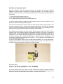
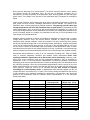
Kuster Company
2900 E. 29th Street
Long Beach, CA USA 90806
Telephone 562-595-0661 Fax 562-426-7897 E-Mail [email protected]
KUSTER K10 ELECTRONIC GAUGES
OPERATION MANUAL
____________________________________________________________________________
ATTENTION:
K10 GAUGES BOTH STRAIN AND QUARTZ OF ALL SIZES:
DURING ASSEMBLE/ DISASSEMBLE, WRENCHES ARE TO BE PLACED ON
THE CLOSEST FLATS. NO PIPE WRENCHES ARE TO BE USED ON
KUSTER MEMORY GAUGES. WISES WITH ROUND HALF CLAMPS ARE
RECOMMENDED FOR FIXING THE GAUGES FOR DISASSEMBLE
PROCEDURES.
IN ORDER TO AVOID TOOL MALFUNCTIONING, O’RINGS UNDER THE
ELECTRONICS HOUSING SHOULD BE REPLACED STRICTLY ACCORDING
THE PROCEDURE, DESCRIBED AT THE END OF THIS MANUAL.
WARNING:
ALL ELECTRONIC GAUGES: UNDER NO CIRCUMSTANCES IS THE
TEMPERATURE RATING OF THE BATTERIES TO BE EXCEEDED.
WORK PREPARATION:
1. Make sure that the tool is able to meet the anticipated requirements of the well to be
surveyed, i.e. pressure and temperature limitations.
2. Make sure that the battery temp limit meets the requirements of the well to be surveyed.
3. Check the battery voltage using the supplied battery tester. With the load adapter
attached to the DMM and the battery turn the selector switch to 20 Vdc. Turn on DMM
and read voltage. The load adapter has 380Ω resistor inside which emulates the board.
The voltage of the battery under 380Ω load should be min 3.1 v for the AA type batter
and min 6.1 v for C type. If the new battery has shown very low voltage, the problem
could be in the battery being passivated. In order to depassivate the battery apply Lo
and Hi loads of the tester.
There is another way of checking the battery. Connect battery to the gauge. First you
will get 1 long flash on battery LED. After that, six or less short flashes. Amount of the
short flashes will indicate approximate voltage of battery. For example, if you will get 6
short flashes, it will indicate, that the battery voltage is about 3.6v, which is a maximum
battery charge level. If it will flash 5 times, then the battery voltage is about 3.5v and so
on. Flickering flash with assigned rate will indicate that gauge start sampling. At 1second sample rate you will not get a flickering flash, but a regular short one.
Third method of checking the battery is with a help of the software and is explained in the
software manual.
4. Power comm. box either with gauge battery or thru a wallwart. Connect gauge through
interface-box to the computer.
5. You will get 1 long flash and then 4 short flashes on comm. box for strain gauge and 5
flashes for quartz. After that it will continue to flash in communication mode. If you don’t
get right amount of flashes, tool and battery feasibility should be questioned.
6. Program the gauge with desired rate. (See software manual for a more detailed
explanation of programming options).
CAUTION: DO NOT DISCONNECT GAUGE DURING DATA TRANSMISSION.
7. Disconnect gauge from the interface box.
8. Apply a bead of Kuster hi-temp thread lube to all threads and across o’ring glands.
9. Disconnect the buffer tube assembly from transducer sub.
2
10. Drop some oil into the transducer sub until it’s full. Never insert syringe or any other
device into the transducer port more than 1/8”, as damage to transducer may occur.
11. Using oil pump, fill buffer tube assembly with a light mineral oil. Don’t try too hard
pushing the pump lever. Slow, but steady force until oil flows from the end of the tube,
that’s all you need.
12. Install buffer tube assembly on the gauge.
13. Install tandem sub on the gauge with external RTD.
If gauge does not have an external RTD, fill the tandem sub with oil, before installing it on
the gauge. Wipe the tandem sub out and wrap a scotch tape over the hole.
14. Install bull nose.
Now tool is ready and can be delivered to the well site.
AFTER ARRIVAL:
1. Connect the battery and note date and time of connection
2. Install battery housing hand tight and finishing tightening with wrenches. Do not over
torque.
3. Connect wireline socket.
4. If it is a gauge without external RTD, put gauge in vertical position and take the scotch
tape off the tandem sub hole.
5. With the lubricator pressured up, allow the gauge at least 15 minutes within the lubricator,
to stabilize before running in the hole.
6. If a static gradient is being run, allow at least ten minutes per stop to allow the gauge to
stabilize and to provide for a sufficient number of samples to be recorded.
Note:
The tool should not be pulled in or out of the hole faster than 50 m/min.
AFTER THE SURVEY:
1. Pull gauge out of the well.
2. Wash down exterior of tool and wipe dry.
3. Remove battery housing and disconnect the battery (note the time and date).
4. Disconnect tandem sub from the gauge.
5. Disconnect buffer tube assembly.
6. Wash down nose of tool, tandem sub and buffer tube assembly with solvent.
7. Flush transducer port with solvent using syringe and allow to drain.
8. Flush and fill buffer tube assembly with clean silicone oil and set aside.
3
9. Connect gauge through comm. box to the computer, wait for 4 (strain gauge), and 5
(quartz gauge) LED flashes on comm. box and download data to the hard drive (See
software operational manual).
CAUTION:
DO NOT DISCONNECT GAUGE DURING DATA TRANSMISSION.
10. Remove old o’rings from I/O connector side of the gauge.
11. Wipe clean the threads and o’ring surfaces and inspect visually all threads for signs of
damage, galling and etc.
12. Install two new o’rings under the battery housing, (C-ring for 1-1/5” K10 SS gauge).
13. Lube threads with Kuster high temp lube.
14. Program tool for 2 point DWT.
15. Install battery and battery housing.
16. Run 2 point DWT.
17. Download the data from the gauge.
18. Review, record & file 2 point DWT.
19. Fill transducer port with fresh oil and install buffer tube assembly onto it.
20. Install tandem sub and bull nose.
DISASSEMBLE/ ASSEMBLE K10 STRAIN 1-1/4” AND K10 QUARTZ 1-1/4” GAUGES IN
ORDER TO CHANGE O’RINGS UNDER THE ELECTRONIC HOUSING
The frequency of changing o’rings under an electronic housing should be dependent on well fluid
types, temperature and gauge usage intensity. With high content H2S we recommend changing
these o’rings every 6 months or 1000 hours in well, which ever comes first.
The frequency of changing o’rings under battery housing is up to the tool operator discretion.
They should be replaced at the first evidences of wear.
All Kuster electronic gauges are furnished with Parker Company Viton o’rings, which cover the
majority of well fluids in the field, however the last decision on which type of o’rings to use is up to
the operator of the gauge.
A wrong choice could lead to tool malfunctioning and denial of warranty. Consult with the o’ring
manufacturer, if you are not sure that these o’rings are suitable for your applications. It is mainly
a concern for the well fluids with high content of H2S.
Electronic housing disassembly:
1. Unscrew slotted nut from the top of the LEMO connector with a fork wrench, which
comes with accessories.
2. Push connector just below the keyway cutout in the housing.
3. With the connector being below the keyway, carefully unscrew electronic housing from
the pressure sub.
4. Remove old o’rings.
5. Check thread and o’ring grooves and lubricate them with Kuster lube grease.
4
6. Replace o’rings on the pressure sub and lube them.
7. Check connector’s o’ring and replace if necessary.
Reassembly:
1. Extend telescopic clip through the keyway end of the housing.
2. Grab the connector with the clip.
3. Slide electronic board with connector through the housing, but keep connector below the
keyway.
4. With connector below the keyway, screw electronic housing onto pressure sub and
tighten it.
5. Pull connector through the keyway.
6. Slide slotted nut over the telescopic clip.
7. Slide fork wrench over the telescopic clip.
8. Screw the slotted nut onto the end of the connector and tighten it with a fork wrench.
DISASSEMBLE/ ASSEMBLE K10 STRAIN 3/4” GAUGE IN ORDER TO CHANGE O’RINGS
UNDER THE ELECTRONIC HOUSING AND BUFFER TUBE SUB
1. Fix gauge (transducer sub) in the wise with round clamps
2. Unscrew and pull out: LEMO connector to the length, which would allow you to unsolder
the connector.
3. Unscrew and pull out electronic housing
4. Unsolder electronic board from the transducer
5. Unscrew buffer tube sub from transducer sub
6. Remove old o’rings and PEEK back-up rings
7. Check threads and o’ring grooves and lubricate them with Kuster lube grease.
8. Replace o’rings and PEEK back-up ring and lubricate them
9. Reconnect the transducer sub with the buffer tube sub (35 ft-lb torque).
10. Re-solder circuit board to the transducer wiring
11. Slide electronics housing over the circuit board and tighten up with 25 ft-lb torque.
12. Re-solder LEMO connector to the board wiring.
13. Screw LEMO connector back to the electronic housing, using small amount of locktite or
similar compound to secure LEMO connector in the housing…
DISASSEMBLE/ ASSEMBLE K10 QUARTZ 3/4”GAUGE IN ORDER TO CHANGE O’RINGS
UNDER THE ELECTRONIC HOUSING AND BUFFER TUBE SUB.
1. Fix gauge (transducer sub) in the wise with round clamps.
2. Unscrew and pull out: LEMO connector to the length, which would allow you to unsolder
the connector.
3. Unscrew and pull out electronic housing
4. Remove old o’rings and back-up ring
5. Check threads and o’ring grooves and lubricate them with Kuster lube grease.
6. Replace o’rings and back-up rings and lubricate them
Assemble in the reverse order
DISASSEMBLE/ ASSEMBLE K10 STRAIN 1”AND QUARTZ 1”GAUGE IN ORDER TO
CHANGE O’RINGS UNDER THE ELECTRONIC HOUSING AND BUFFER TUBE SUB.
1.
2.
3.
4.
5.
6.
Fix gauge (transducer sub) in the wise with round clamps
Unscrew set 4 set screws to release LEMO.
Pull out LEMO and collars from the housing.
Unscrew and pull out electronic housing.
Remove old o’rings and back-up rings
Check threads and o’ring grooves and lubricate them with Kuster lube grease.
5
7. Replace o’rings and back-up rings and lubricate them
Assemble in the reverse order.
DISASSEMBLE/ASSEMBLE K10 QUARTZ 1.5” SOUR SERVICE GAUGE IN ORDER TO
CHANGE O’RINGS AND METAL C-RING UNDER ELECTRONIC HOUSING.
The frequency of changing O-rings and C-ring under the electronic housing should be dependent
on well fluid types, temperature and gauge usage intensity. With high content H2S we
recommend changing these O-rings every month or 80 hours in well, whichever comes first.
But the final decision on Seals replacement frequency is have to be based on operator’s
company policies and instructions.
The frequency of changing O-rings and C-ring under battery housing is up to the tool operator
discretion. They should be replaced at the first evidences of wear.
All Kuster electronic gauges are furnished with Parker Company Viton O-rings, which cover the
majority of well fluids in the field, however the last decision on which type of O-rings to use is up
to the operator of the gauge.
A wrong choice could lead to tool malfunctioning and denial of warranty. Consult with the O-rings
manufacturer, if you are not sure that these O-rings are suitable for your applications. It is mainly
a concern for the well fluids with high content of H2S.
Electronic housing disassembly:
8. Unscrew slotted nut from the top of the LEMO connector with a fork wrench, which
comes with accessories.
9. Push connector just below the keyway cutout in the housing.
10. With the connector being below the keyway, carefully unscrew electronic housing from
the pressure sub.
11. Remove old O-rings and C-ring.
12. Check thread and O-rings grooves and lubricate them with Kuster lube grease.
13. Replace O-rings and C-ring on the pressure sub and lube them.
14. Check connector’s O-rings and replace if necessary.
Reassembly:
9. Extend telescopic clip through the keyway end of the housing.
10. Grab the connector with the clip.
11. Slide electronic board with connector through the housing, but keep connector below the
keyway.
12. With connector below the keyway, screw electronic housing onto pressure sub and
tighten it until C-ring is crushed.
13. Pull connector through the keyway.
14. Slide slotted nut over the telescopic clip.
15. Slide fork wrench over the telescopic clip.
16. Screw the slotted nut onto the end of the connector and tighten it with a fork wrench.
6
7
8
9
10
11
12
13
BATTERY VOLTAGE AND USAGE
Given the variety of tests and surveys that exist in the downhole environment, a definitive
guideline for battery usage is impossible. The technician needs to use a certain amount of
judgment on when to use or not to use a particular battery pack. The decision should be based on
three things.
1. The length of the test (survey) to be run.
2. The amount of time a battery has been used.
3. The voltage the battery shows on the communication box.
In order to measure battery’s charge level, connect battery to the comm. Box, which in its turn
should be connected to the gauge and computer
The circuit board electronics of both the strain and quartz gauges requires approximately 3 volts
minimum to operate correctly. And the quartz transducer requires 6.5 volts minimum to operate
correctly. Since lithium batteries maintain the maximum stated voltage for the useable life of the
battery; once the voltage starts to drop their useable life is short indeed.
For example: Our AA batteries are rated at 1.5Ah. But this number is taken after 80% of the life
has been used. The remaining voltage is approximately 2.5volts. Not enough to operate the
gauge properly. 1Ah leaves approximately 3-3.2volts left. Realistically the battery should not be
used past 1Ah. Of course this is where the judgment of the operator comes into play. Also, do not
forget that sometimes lithium batteries passivate (go to sleep) and need to be awakened. This
can cause the voltage to be much lower than it really is. You can wake them up by shaken them
up or using the battery load tester.
In order to check battery voltage, insert the load tester with battery on it into the Multi-meter.
Voltage, that you will see, is the voltage of the battery without any load. Push 100om button on
the tester to imitate circuit board load and observe battery voltage.
Recommendation:
AA lithium- with 380 ohm load adapter- 3.1 volts.... Do not use.
C lithium - with 380 ohm load adapter- 6.1 volts….Do not use.
If you use batteries all the time, there is a little chance they’re going to passivate (read the
Passivation of Lithium Cells chapter down-bellow). But if you think it’s happened, push 10om
button on the Quartz load tester and 20om on Strain for wakening up them up.
14
LITHIUM OXYHALIDE PRIMARY CELLS
Basic Handling Note:
With the exception of QTC and PC cells, every Electrochem lithium battery is equipped with an
internal safety fuse. These very fast acting fuse elements can be opened with even the slightest
short circuit. Therefore, use care in handling these products to prevent any potential short circuit
condition. If a cell fuse should open, do not attempt to repair it yourself. Contact Electrochem
distributor for assistance.
Safety
Although every Electrochem lithium battery is designed and manufactured for safe operation, it is
important to observe several key points:
•
•
•
•
•
•
Never store or operate a battery above its designated maximum temperature.
Never store cells of different chemistry, size, age, or discharge depth.
Under no circumstances should the terminal cap of a cell be removed.
Do not crush, puncture, or attempt to disassemble a cell or battery pack.
Never use excessive force, or hammering to free batteries lodged inside any type of
housing.
Standard industrial safety practices, such as the wearing of eye protection, should always
be employed when handling batteries or other high power energy devices.
Shipping
Electrochem lithium batteries are shipped in full compliance with all rules and regulations
governing proper packaging as set forth by the United Nations and enforced by various
international agencies. Whenever re-shipping lithium batteries, the customer must ensure that all
methods used are in compliance with the latest regulations.
Disposal
The regulations concerning the disposal of lithium batteries vary widely. Local disposal
regulations differ and subject to change. Contact the proper Environmental Agency in your area
for questions regarding the disposal of lithium batteries.
Specifications 3B1065 Series PMX150 (AA cells)
Open circuit voltage at room temperature……………………………………………….…….3.9V
Rated discharge current………………………………………………………………….…….20mA
Rated capacity…………………………………………………………………………………..1.6 Ah
Maximum continuous discharge current……………………………………………...…….150 mA
Operating temperature range………………………………………………………..-40C to +150C
-40F to +302F
Weight………………………………………………………………………………………….…..15 g
Safety fuse…………………………………………………………………………….…….....4 A link
Lithium weight…………………………………………………………………………………….0.5 g
This product is not restricted under DOT or IATA shipping regulations
PASSIVATION OF LITHIUM CELLS
Passivation is a phenomenon of liquid cathode lithium cells related to the interaction of the
metallic lithium anode and the oxyhalide electrolyte. A thin passivation layer forms on the surface
of the anode at the instant the electrolyte is introduced into the cell. This layer is important
because it protects the anode from reaction while the cell is dormant – resulting in a long shelflife.
15
During low rate discharge (5-10 microamps/cm2), the lithium ions that allow the cell to operate
can migrate through the passivation layer. As the rate of discharge increases (0.1-1.0
milliamp/cm2), so does the porosity of the passivation layer, allowing greater ion flow and higher
power output. This change in the structure of the passivation layer is illustrated in the diagram
below.
Under normal conditions, the thin passivation layer does not degrade cell performance. When the
layer grows too thick, however, discharge performance may be affected. The growth of the
passivation layer is influenced greatly by storage conditions. Long storage periods and/or high
storage temperatures will cause the passivation layer to grow thicker. A passivated cell may
exhibit voltage delay, which is the time lag that occurs between the application of a load on the
cell and the voltage response. As the passivation layer thickens, the voltage delay becomes more
severe. Eventually though, the voltage of a passivated cell will rise to a level equivalent to the
load voltage of an unpassivated cell.
Adjusting storage conditions to reduce the likelihood of passivation is the best way to reduce
voltage delay. However, there are several effective methods for dealing with excessive
passivation when storage conditions cannot be controlled. The layer can be kept from growing
too thick by maintaining a light load on the cell during storage. Alternatively, a higher load, placed
on the cell at regular intervals during storage, or just prior to the anticipated start-up of the cell,
can be used to disrupt the passivation layer and restore normal performance. Both of these
methods will have an impact on the useable capacity of the cell. In particular, a low rate discharge
tends to increase the normal self-discharge reaction of the cell and reduce the available capacity.
.
Electrochem utilizes additives in many of its cell chemistries (including CSC, PMX and MWD
cells) to minimize passivation formation and enhance restart performance. Under most
operating conditions, depassivation of an Electrochem cell is unnecessary. However, under
some more severe conditions (such as high temperature storage) it may be beneficial to
depassivate a cell. For the most effective depassivation, Electrochem generally recommends
discharging a cell near the specified maximum continuous discharge rate. The table below shows
the maximum discharge current and recommended depassivation load for several of the most
widely used Electrochem cell models. Note that the load given in the table will yield close to the
rated maximum continuous current for an individual cell. The load should be adjusted
accordingly for multi-cell battery packs. A depassivation load should be applied until the cell
voltage recovers to a normal level (> 3.0 volts). The recovery duration will depend on the severity
of the passivation. Any questions regarding the performance of Electrochem cells should be
directed to an Electrochem Sales or Customer Service representative, or to an authorized
Electrochem dealer.
Cell Type
Part Number
BCX AA
BCX C
BCX D
BCX DD
CSC AA
CSC C
CSC D
CSC DD
PMX AA
PMX C
PMX CC
PMX DD
VHT C
MWD CC
3B0064
3B0070
3B0075
3B0076
3B0024
3B0030
3B0035
3B0036
3B1065
3B3700
3B3000
3B2800
3B4800
3B3200
Maximum Rated
Discharge (mA)
100
500
1000
3000
150
1000
2000
4000
150
500
500
2000
250
1000
Depassivation Load
(Single Cell) (ohm)
30
6
3
1
20
3
2
1
20
6
6
2
10
3
16