1
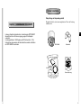
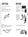
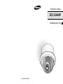
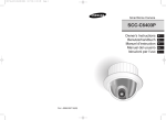
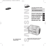
SmartDome Camera
SCC-C6403P
Owner’s Instructions
Benutzerhandbuch
Manuel d’instruction
Manual del usuario
Istruzioni per l’uso
Part : AB68-00571A(00)
E
D
F
Es
I
Important Safety Instructions
1. Read these instructions.
2. Keep these instructions.
3. Heed all warnings.
4. Follow all instructions.
5. Do not use this apparatus near water.
6. Clean only with dry cloth.
7. Do not block any ventilation openings, Install in accordance with the
manufacturer's instructions.
8. Do not install near any heat sources such as radiators, heat registers, or
other apparatus (including amplifiers) that produce heat.
9. Do not defeat the safety purpose of the polarized or grounding- type plug. A
polarized plug has two blades with one wider than the other.
A grounding type plug has two blades and a third grounding prong.
The wide blade or the third prong are provided for your safety. If the
provided plug does not fit into your outlet, consult an electrician for
replacement of the obsolete outlet.
10. Protect the power cord from being walked on or pinched particularly at
plugs, convenience receptacles, and the point where they exit from the
apparatus.
11. Only use attachments/accessories specified by the manufacturer.
12. Use only with cart, stand, tripod, bracket, or table specified by the
manufacturer, or sold with the apparatus.
13. Unplug this apparatus. When a cart is used, use caution when moving the
cart/apparatus combination to avoid injury from tip-over.
14. Refer all servicing to qualified service personnel. Servicing is required
when the apparatus has been damaged in any way, such as power-supply
cord or plug is damaged, liquid has been spilled or objects have fallen into
the apparatus the apparatus has been exposed to rain or moisture, does
not operate normally, or has been dropped.
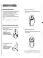
Safety Precautions
The purpose of this information is to ensure proper use of this product to
prevent danger or damage to property. Please be sure to observe all
precautions.
* The precautions are divided into "Warnings" and "Cautions" as
distinguished below:
Warning: Ignoring this warning may result in death or serious injury.
Caution: Ignoring this caution may result in injury or damage to property.
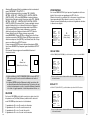
Warning instructions alert you to
a potential risk of death
or serious injury.
Caution instructions alert you to the
potential risk of injury or
damage to property.
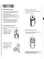
Warning
1. Be sure to use only the standard adapter which is specified in the
specification sheet.
Using any other adapter could cause fire, electrical shock, or damage to
the product.
2. When connecting the power supply and signal wires, check the external
connection terminals before connecting them. Connect the alarm signal
wires to the alarm terminals, the AC adapter to the AC power input
receptacle, and the DC adapter to the DC power input, making sure that
the correct polarity is observed.
(Connecting the power supply incorrectly may cause fire, electrical shock,
or damage to the product.)
3. Do not connect multiple cameras to a single adapter.
(Exceeding the capacity may cause abnormal heat generation or fire.)
(A falling camera may cause personal injury.)
4. Securely plug the power cord into the power receptacle.
(Insecure connection may cause fire.)
5. When installing the camera on a wall or ceiling, fasten it securely and
firmly. (A falling camera may cause personal injury.)
E
6. Do not place conductive objects (e.g., screwdrivers, coins, and metal
things) or containers filled with water on top of the camera. (Doing so may
cause personal injury due to fire, electrical shock, or falling objects.)
FCC STATEMENT
7. Do not install the unit in humid, dusty, or sooty locations.
(Doing so may cause fire or electrical shock.)
This device complies with Part 15 of the FCC Rules. Operation is subject to
8. If any unusual smells or smoke come from the unit, stop using the product.
In such case, immediately disconnect the power source and contact the
service center. (Continued use in such a condition may cause fire or
electrical shock.)
(1) This device may not cause harmful interference, and
9. If this product fails to operate normally, contact the store of purchase or
your nearest service center. Never disassemble or modify this product in
any way. (SAMSUNG is not liable for problems caused by unauthorized
modifications or attempted repair.)
10. When cleaning, do not spray water directly onto parts of the product.
(Doing so may cause fire or electrical shock.)
Wipe the surface with a dry cloth. Never use detergents or chemical
cleaners on the product, as this may result in discoloration of surface or
cause damage to the finish.
Caution
1. Do not drop objects on the product or apply strong shock to it. Keep away
from a location subject to excessive vibration or magnetic interference.
2. Do not install in a location subject to high temperature (over 122°F), low
temperature (below 14°F), or high humidity.
(Doing so may cause fire or electrical shock.)
3. Avoid a location which is exposed to direct sunlight, or near heat sources
such as heaters or radiators.
(Neglecting to do so may result in a risk of fire.)
4. If you want to relocate the already installed product, be sure to turn off the
power and then move or reinstall it.
5. Install in a well-ventilated location.
6. Remove the power plug from the outlet when there is a lightning storm.
(Neglecting to do so may cause fire or damage to the product.)
the following two conditions:
(2) This device must accept any interference received, including interference
that may cause undesired operation.
Note: This equipment has been tested and found to comply with the limits for
a Class A digital device, pursuant to part 15 of the FCC Rules. These
limits are designed to provide reasonable protection against harmful
interference when the equipment is operated in a commercial
environment. This equipment generates, uses, and can radiate radio
frequency energy and, if not installed and used in accordance with the
instruction manual, may cause harmful interference to radio
communications. Operation of this equipment in a residential area is
likely to cause harmful interference in which case the user will be
required to correct the interference at his own expense.
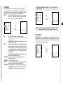
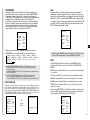
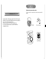
Before Usage
This is a basic instruction manual for the SCC-C6403P user.
It contains all the instructions needed to use the SCC-C6403P
from a simple introduction of the control locations and functions of
the SCC-C6403P to installation methods in the set up menu.
We recommend all users of the SCC-C6403P from the advanced
user who has used similar cameras before to the general user to
read the instruction manual before using.
The most frequently used feature in the SCC-C6403P would be
the SCC-C6403P Setup Menu.
The SCC-C6403P Setup Menu is explained in detailed in
"Chapter 3 Setup Menu Overview".
The instructional manual is best used when read from beginning
to end, but for users wanting to read only the part they need here
are the Chapter summaries.
"Chapter 1 SCC-C6403P Overview" includes a brief introduction
of the SCC-C6403P, part names and functions, and Switch
Settings.
"Chapter 2 SCC-C6403P Installation" explains the installation
procedures of the SCC-C6403P and provides preparation and
installation environment requirements.
"Chapter 3 Setup Menu Overview" presents the structure of the
Setup menu for the SCC-C6403P including a detailed explanation
of the functions performed in each submenu.
"Appendix SCC-C6403P Product Specifications" contains
product specifications of the SCC-C6403P in itemized categories.
1-1
Table of contents
Before Usage ...............................................................................................................1-1
Chapter 1 SCC-C6403P Overview ...........................................................................1-4
SCC-C6403P Introduction ...........................................................................1-5
Locations of Control… .................................................................................1-6
ADAPTER CONNECTION ..........................................................................1-8
INITIAL SETTING........................................................................................1-9
Setting RS-422A/RS-485 termination ........................................................1-10
E
Chapter 2 SCC-C6403P Installation.........................................................................2-1
Before Installing...........................................................................................2-2
Preparing the Cables...................................................................................2-3
Cable Connection ........................................................................................2-4
Installing SCC-C6403P................................................................................2-5
Installing the Camera ..................................................................................2-8
Chapter 3 Setup Menu Overview .............................................................................3-1
Structure of the Setup Menu........................................................................3-2
1. CAMERA SET MENU .............................................................................3-4
- CAMERA ID .........................................................................................3-4
- V-SYNC................................................................................................3-5
- COLOR/BW..........................................................................................3-6
- MOTION DET.......................................................................................3-7
- ZOOM SPEED .....................................................................................3-8
- DIGITAL ZOOM ...................................................................................3-9
- DISPLAY ZOOM ..................................................................................3-9
- DISPLAY P/T .......................................................................................3-9
- EXIT ...................................................................................................3-10
2. VIDEO SET MENU ...............................................................................3-10
- IRIS ....................................................................................................3-10
- ALC .................................................................................................3-10
- BLC ...............................................................................................3-10
- MANU .............................................................................................3-11
- SHUTTER ..........................................................................................3-12
- FLICKERLESS ................................................................................3-12
- AGC ...................................................................................................3-13
- MOTION.............................................................................................3-13
- WHITE BAL........................................................................................3-14
- DIS .....................................................................................................3-15
- FOCUS MODE...................................................................................3-16
- SPECIAL............................................................................................3-16
- EXIT ...................................................................................................3-17
3. PRESET ................................................................................................3-17
- POSITION SET .................................................................................3-18
- PRESET ID........................................................................................3-18
- VIDEO SET........................................................................................3-18
- PRESET SPEED ...............................................................................3-18
- DWELL TIME.....................................................................................3-18
- IMAGE HOLD ....................................................................................3-18
- EXIT...................................................................................................3-18
1-2
4. ZONE SET...............................................................................................3-19
- ZONE DIR SET....................................................................................3-19
- ZONE AREA SET ................................................................................3-20
- LOCATION .......................................................................................3-21
- ZONE ID SET ...................................................................................3-21
- ZONE ENABLE.................................................................................3-21
5. AUTO SET...............................................................................................3-22
- AUTO PAN ..........................................................................................3-22
- POSITION SET.................................................................................3-22
- SPEED..............................................................................................3-23
- DWELL TIME....................................................................................3-23
- PATTERN ............................................................................................3-23
- SCAN...................................................................................................3-24
- AUTO PLAY.........................................................................................3-25
- AUTO RETURN................................................................................3-25
- AUTO PLAY......................................................................................3-25
- PLAY NUMBER ................................................................................3-25
6. ALARM SET ............................................................................................3-26
- ALARM PRIORITY SET ......................................................................3-26
- ALARM IN SET....................................................................................3-26
- ALARM OUT SET................................................................................3-26
- AUTO SET...........................................................................................3-27
- AUX OUT CONTROL ..........................................................................3-27
7. OTHER SET ............................................................................................3-27
- PROPORTINAL P/T ............................................................................3-27
- TURBO P/T..........................................................................................3-28
- AUTO CAL...........................................................................................3-28
- AUTO FLIP ..........................................................................................3-28
- CAM RESET........................................................................................3-28
- LANGUAGE.........................................................................................3-28
- PASSWORD........................................................................................3-28
8. SYSTEM INFO ........................................................................................3-29
9. Short Keys ...............................................................................................3-30
Chapter 1 SCC-C6403P Overview
In this chapter we will briefly introduce the SCC-C6403P
and show main functions, locations of control and Switch
Setting.
E
Product specifications .......................................................................................... 3-32
1-3
1-4
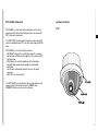
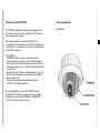
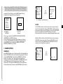
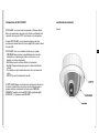
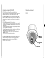
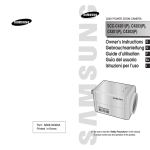
SCC-C6403P Introduction
Locations of Control
SCC-C6403P is a zoom lens built in smart dome camera which
provides you with the best monitoring function in connection with
CCTV at banks or companies.
FRONT
E
The SCC-C6403P is a high quality surveillance camera using x32
zoom lens and digital zoom IC, it can catch clear images up to 320
times.
SCC-C6403P has a variety of functions such as;
- DAY/NIGHT to improve the sensitivity by automatic conversion
into the black and white mode at night or in the environment with
low illumination,
- White Balance to control the brightness to the illumination,
- Backlight Compensation under spotlight or utmost bright
illumination,
- Auto Focus to automatically adjust the focus to the subject
movement,
- PAN/TILT for an easy operation.
The SCC-C6403P uses an Alarm function for alert situations and
moving camera in the direction you want, ZOOM-IN and
ZOOM-OUT functions can be remote controlled.
1-5
1-6
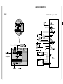
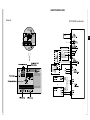
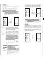
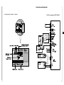
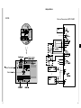
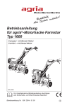
ADAPTER CONNECTION
BACK
SCC-C6403P Adapter BOARD
E
AC 24V
OUT
POWER
AC 24V
OUT
POWER
1-7
1-8
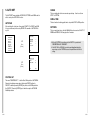
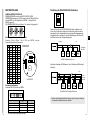
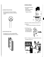
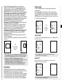
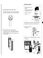
INITIAL SETTING
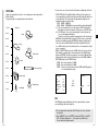
Setting RS-422A/RS-485 termination
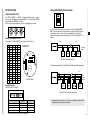
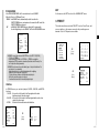
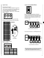
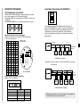
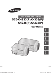
CAMERA ADDRESS SETUP
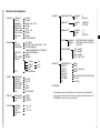
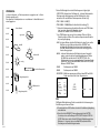
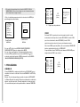
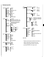
Use SW701, SW702, or SW703 for Camera Address setup. You may
allocate up to 255 addresses by using SW701 to set the 3rd digit, SW702
the 2nd digit, and SW703 the 1st digit.
EX) In case of Camera Address 1, see the following figure for setup.
SW701
SW703
SW702
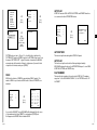
Setting communication Protocol
Use number 1~4 PIN of SW704 to set communication Protocol.
PIN
Comp
PIN1
PIN2
PIN3
PIN4
A
OFF
OFF
OFF
OFF
B
ON
OFF
OFF
OFF
C
OFF
ON
OFF
OFF
D
ON
ON
OFF
OFF
E
OFF
OFF
ON
OFF
F
ON
OFF
ON
OFF
G
OFF
ON
ON
OFF
H
ON
ON
ON
I
OFF
OFF
OFF
ON
J
ON
OFF
OFF
ON
K
OFF
ON
OFF
ON
L
ON
ON
OFF
ON
M
OFF
OFF
ON
ON
N
ON
OFF
ON
ON
O
OFF
ON
ON
ON
P
ON
ON
ON
ON
1
2
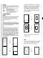
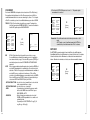
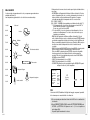
As it is shown in the structure map, when Controller and RS-422A/RS485 is connected it should be terminated according to the Cable feature
of impedance on the each end of the transmitting line to transfer the
signals in long distance by controlling the reflection of the signals to the
lowest.
Division
E
n < 32
A : SAMSUNG HALF
B : SAMSUNG FULL
Termination
SW1-ON
SEE INSTRUCTION MANUAL
ON 1 2 3 4 5 6 7 8
SW704
(x100)
(x10)
(x1)
<RS-485 Half Duplex Organization>
SW701 SW702 SW703
OFF
Termination: using numbers 1 and 2 PIN, turn to ON and it will be terminated.
n < 32
(BOTTOM VIEW)
Division
Division
SW1-ON
SW2-ON
Baud Rate Setting
Use PIN 5 and 6 of SW704.
1
2
3
4
5
6
7
8
<RS-422A/RS-485 Full Duplex Organization>
ON
OFF
SW 704
PIN 5
PIN 6
4800 BPS
ON
ON
9600 BPS
OFF
ON
19200 BPS
ON
OFF
38400 BPS
OFF
OFF
BAUD RATE
1-9
The factory default setting is set to 9600BPS.
❈ A communication error may occur if you connect multiple cameras that are
assigned the same address in the network.
1-10
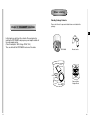
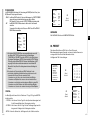
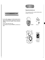
Before Installing
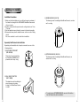
Checking Package Contents
Chapter 2 SCC-C6403P Installation
Please check that all components listed below are included in the
package:
E
In this chapter, we will check the contents of the package before
installing the SCC-C6403P, and prepare a power adapter suitable for
the power supply system.
(Power Consumption: 18W; Voltage: AC24V, 1.5A)
Then, we will install the SCC-C6403P and connect the cables.
SCC-C6403
Bracket anchor
Owner’s
Instructions
AC 24V
OUT
POWER
Screws
Cover Body
2-1
Camera Holder
Adapter Board
2-2
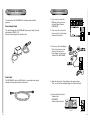
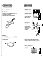
Preparing the Cables
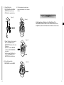
Cable Connection
Power Adapter Cable
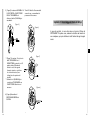
1. First, connect one end of the
BNC video cable connector to
the Video Output Terminal
(VIDEO OUT)
The cable that plugs into the SCC-C6403P power input receptacle has the
rated voltage of AC24V, 1.5A.
Check the rated voltage before using the cable.
2. Then, connect the other end of
the connector to the Video Input
Terminal of the monitor.
To install and use the SCC-C6403P, the following cables should be
prepared.
E
3. Now connect the Power Adapter
Cable. Use a driver to screw
one part of the two lines of
Power Adapter to Power Input
Terminal of the SCC-C6403P.
Video Cable
The SCC-C6403P's cable is a BNC Cable for connecting the video-output
terminal to the video-input terminal of the monitor.
4. Adjust the switch on the Power Adapter to the proper voltage.
Then, connect the Power Adapter's plug to the Power Connector.
5. Connect the Remote Control
Terminal of the
SCC-C6403P
and the external Controller.
Controller
Adapter BOARD
2-3
2-4
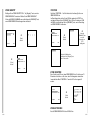
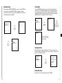
Installing SCC-C6403P
Installation Precautions
1) Make sure that the installation site can sufficiently support a minimum of
four times the net weight of the SCC-C6403P SmartDome Camera and
other accessories.
2) Install in an area where the space above the ceiling board is over 18 cm
(7 in.) high.
3) Use the supplied screws to fasten the camera to the bracket assembly.
4) Keep persons away from the installation area, as there is a risk of falling
objects.
Also, move valuables to a safe location before installation.
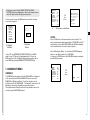
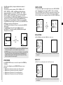
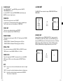
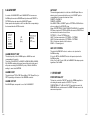
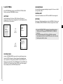
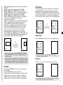
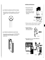
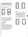
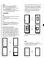
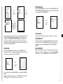
3) INDOOR HOUSING (SHG-120)
This housing is used for installing the SmartDome Camera to an indoor
wall or a ceiling.
E
Separately Sold Products for Installation
Depending on the installation site, it may be convenient to use one of the
following products.
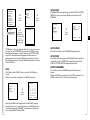
1) CEILING MOUNT BRACKET
(SBR-100DCM)
This bracket is used for installing
the SmartDome CAMERA in the
plenum above the drop ceiling.
4) OUTDOOR HOUSING (SHG-220)
This housing is used for installing the SmartDome Camera to an
outdoor wall or a ceiling.
2) WALL MOUNT ADAPTOR
(SADT-100WM)
This adaptor is used for installing the
indoor housing or the outdoor
housing for the SmartDome Camera
on a wall.
❈ To install and use OUTDOOR HOUSING, remove the Clear Case
from the Camera body before installation.
2-5
2-6
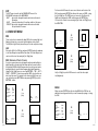
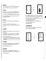
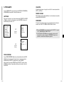
Installing the Camera
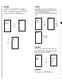
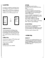
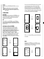
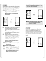
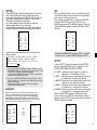
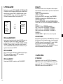
5) CEILING MOUNT ADAPTOR (SADT-100CM)
This adaptor is used for installing the indoor housing or the outdoor
housing for the SmartDome Camera to a concrete ceiling.
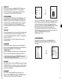
1. [Figure 1] Install the structure on the
ceiling.
(Refer to Installation reference
for the Length of the structure)
* Built in by the builder of the structure
E
[Figure 1]
2. Make a hole in the ceiling where the camera will be installed.
(The hole should be about ø185)
3. [Figure 2] Assemble the
BRKT-ANCHOR on the ceiling
and screw the 4 bolts in.
6) POLE MOUNT ADAPTOR (SADT-100PM)
This adaptor is used for installing the WALL MOUNT ADAPTOR
(SADT-100WM) to a pole that is over 8 cm (2.76 in.) in diameter.
[Figure 2]
4. [Figure 3,4] Connect the various cables to the CAMERA ADAPTER.
(See page 2-4)
[Figure 3]
[Figure 4]
2-7
2-8
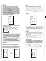
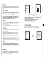
5. [Figure 5] Match the
BRKT-ANCHOR and CAMERA
ADAPTER and use 4screws
(PH M4 x 8) to assemble them.
6. Pull the safety wire from the case
body, and assembly it to the camera
holder.
Chapter 3 Setup Menu Overview
[Figure 5]
[Figure 6]
In this chapter, we will look over the Setup Menu of the
SCC-C6403P, First we'll look over the overall structure of the
Setup Menu, and then we'll look at the functions of each menu.
7. [Figure 7] Match the 3 holes on the
back of the CAMERA and the
CONNECTOR and turn it left about
15 degrees.
(Check the sound of LOCKING
and that the LEVER-LOCKING
is in place)
* Use the screws (BH M3 x L8) to
connect the CAMERA and the
ADAPTER so they don't move.
8. [Figure 8] Assemble the
COVER-BODY onto the DOME.
2-9
E
[Figure 7]
[Figure 8]
3-1
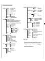
Structure of the Setup Menu
ALARM SET
CAMERA SET
CAMERA ID
V-SYNC
COLOR/BW
MOTION DET
ZOOM SPEED
DIGITAL ZOOM
DISPLAY ZOOM
DISPLAY P/T
EXIT
ON.../OFF
INT/LINE...
COLOR.../BW.../AUTO...
OFF/ON...
1/2/3/4
0FF/X2 ~ X10
OFF/ON
OFF/ON
QUIT/SAVE/PRESET
ALARM PRIORITY SET
ALARM1~4
EXIT
ALARM IN SET
ALARM1~4
EXIT
ALARM OUT SET
ALARM1~4
MOTION
EXIT
AUTO SET
VIDEO SET
IRIS
SHUTTER
AGC/MOTION
EXIT
ALC.../MANU...
OFF/1/100(1/120)~1/10K/AUTOX2...~X128...
OFF/LOW/HIGH(AGC)
S.SLOW/SLOW/NORM/FAST/F.FAST(MOTION)
ATW1/ATW2/AWC/MANU...
ON/OFF
ONEAF/MF
...
Y-LEVEL
(0)l--C-LEVEL
(0)l--DETAIL
(0)l--RET
QUIT/SAVE/PRESET
POSITION SET
PRESET ID
VIDEO SET
PRESET SPEED
DWELL TIME
IMAGE HOLD
EXIT
...
ON.../OFF
ON.../OFF
1~8
1~60S
ON/OFF
QUIT/SAVE/DEL
ZONE SET
ZONE DIR SET
ZONE AREA SET
EXIT
OFF/ON...
OFF/ON...
QUIT/SAVE
AUTO SET
AUTO PAN
PATTERN
SCAN
AUTO PLAY
RET
1.../2.../3.../4...
1.../2.../3...
1.../2.../3.../4...
...
WHITE BAL
DIS
FOCUS MODE
SPECIAL
PRESET
3-2
ALARM1~4
MOTION
EXIT
AUX OUT CONTROL
1~4
QUIT/SAVE
NO/NC/OFF
QUIT/SAVE
1~3
1~3
QUIT/SAVE
E
OFF/PATTERN1~3/HALF1~2/FULL/SCAN1~4
OFF/PATTERN1~3/HALF1~2/FULL/SCAN1~4
QUIT/SAVE
OUT1
OUT2
OUT3
EXIT
ON/OFF
ON/OFF
ON/OFF
QUIT/SAVE
RET
OTHER SET
PROPORTIONAL P/T
TURBO P/T
AUTO CAL
AUTO FLIP
CAM RESET
LANGUAGE
PASSWORD
EXIT
ON/OFF
ON/OFF
OFF/6H/12H/18H/24H
ON/OFF
...
ENGLISH/FRANÇAIS/DEUTSCH/ESPAÑOL/ITALIANO
ON.../OFF
QUIT/SAVE
SYSTEM INFO
The diagram shown above illustrates the overall structure of the Setup Menu.
In this section, a description of the Setup menu features will enable users of the
SCC-C6403P to tailor it to their personal needs.
3-3
❈ If the power is turned off after PRESET, AUTO PAN, SCAN,
PATTERN function is activated and no other control is made, camera
will do the same function after the power is turned on.
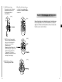
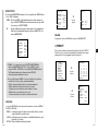
Use the controller to press the MENU selection key and the following
screen will be displayed.
** MAIN MENU **
CAMERA SET...
VIDEO SET...
PRESET ...
ZONE SET...
AUTO SET...
ALARM SET...
OTHER SET...
SYSTEM INFO...
➀ PASSWORD
UNDEFINED
0
1
2
3
4
5
6
7
8
9
(CAMERA ID)
(CAMERA SET)
CAMERA ID
V-SYNC
COLOR/BW
MOTION DET
ZOOM SPEED
DIGITAL ZOOM
DISPLAY ZOOM
DISPLAY P/T
ON...
INT
COLOR...
OFF
3
OFF
OFF
OFF
EXIT
QUIT
➜
Press
[Enter]
❈ " ... " Means there are Sub Menus.
E
✽✽✽✽
V-SYNC
➁ PASSWORD
DEFINED
In case of ➀, use UP/DOWN/LEFT/RIGHT/[ENTER] key for MENU
setup. In case of ➁, type in the 4 digit password first. If correct, the
MENU selection screen like ➀ will be displayed and you will be able to
set up MENU by pressing UP/DOWN/LEFT/RIGHT/[ENTER] key.
In the V-SYNC menu, vertical synchronization can be selected. The
vertical synchronization signal supported by the SCC-C6403P is the INT
mode made by clock inside the SCC-C6403P and LINE mode adjusting
vertical synchronization to the exterior power frequency.
Select LINE and press [Enter]. You will see the LINE LOCK submenu
where you can adjust the phase of the LINE LOCK.
You can use the PHASE menu of the LINE LOCK submenu to assign as
much PHASE as you want.
(CAMERA SET)
1. CAMERA SET MENU
CAMERA ID
The CAMERA ID menu assigns an ID to the SCC-C6403P to be displayed
on the connected monitor.On the CAMERA SET menu screen, select
CAMERA ID to ON and press [Enter]. You will see the sub screen for
deciding on the ID of the SCC-C6403P. The Camera ID can have up to 20
alphanumeric characters, along with several special characters.
The assigned camera ID may be positioned to any desired location on the
screen by using the LOCATION submenu.
3-4
A BCDEFGHIJKL
M N O PQ R S T U V W X
YZ0 1 2 3 4 5 6 7 8 9
: ! -+✻ ( ) /
SP ï î SP
LOCATION...
RET
SCC-C6403........
(LL-PHASE)
CAMERA ID
V-SYNC
COLOR/BW
MOTION DET
ZOOM SPEED
DIGITAL ZOOM
DISPLAY ZOOM
DISPLAY P/T
OFF
LINE...
COLOR...
OFF
3
OFF
OFF
OFF
EXIT
QUIT
➜
Press
[Enter]
PHASE
RET
(-262)I--------
3-5
COLOR/BW
In the COLOR/BW menu, you can switch ON or OFF the IR (infrared) Filter.
In a poor illumination environment, the IR filter is turned off in the BW mode the its
sensitivity increases as high as a black and white camera. On the other hand, the
IR filter is turned on and the sensitivity decreases in the COLOR mode.
COLOR
: The IR Filter is ON and the screen is normal. You can press the
[Enter] key to set the COLOR GAIN LEVEL. And when the AGC
function is on, you can set the AGC COLOER LEVEL.
(CAMERA SET)
(COLOR)
CAMERA ID
V-SYNC
COLOR/BW
MOTION
ZOOM SPEED
DIGITAL ZOOM
DISPLAY ZOOM
DISPLAY P/T
OFF
INT
COLOR …
OFF
3
OFF
OFF
OFF
EXIT
QUIT
❈ In AUTO mode, AGC will be displayed as “---“. You can’t adjust the
settings manually.
(CAMERA SET)
(AUTO)
CAMERA ID
V-SYNC
COLOR/BW
MOTION DET
ZOOM SPEED
DIGITAL ZOOM
DISPLAY ZOOM
DISPLAY P/T
OFF
INT
AUTO...
OFF
3
OFF
OFF
OFF
EXIT
QUIT
➜
Press
[Enter]
BURST
LEVEL
DURATION
RET
ON
LOW
S --|---- L
E
➜
Press
[Enter]
GAIN
AGC COLOR
RET
(0)I-------(0)----I----
Caution : If you use an infrared light source while in AUTO mode, AUTO
switching malfunction and camera AF malfunction may occur.
MOTION DET
BW
: The IR Filter is OFF and the screen is black and white.
(Sensitivity to low light is increased to a level comparable to a black
and white camera.)
Select BW and press [ENTER] and the additional menu to select
BURST ON/OFF will appear.
AUTO
: Select to automatically switch between the COLOR mode and BW
mode depending on the amount of light. In low light conditions, the
IR Filter is turned OFF and the sensitivity to low light is increased
by switching to the BW mode, but in bright light conditions, the IR
Filter is turned ON and the sensitivity is decreased by switching to
the COLOR mode.
Select AUTO and press [ENTER] and the additional menu to select
BW LEVEL and DURATION will appear.
- BURST ON : The color burst signal is output together with black and white
composite video signal.
- BURST OFF : The color burst signal is not output.
- LEVEL
: You can set the brightness level that changes from COLOR mode
to BW mode in 3 steps : LOW, MEDIUM, and HIGH.
- DURATION : Set the HOLDING time for switching between COLOR and BW
mode depending the changes in the amount of light. You can set
the HOLDING time to 10sec (S), 30sec, 60sec, or 300sec( L).
3-6
In MOTION DET, you can set the Motion Detection function, Motion Detection
Sensitivity, and the Area of Motion Detection. If the Motion Detection function
is set, the movement of an intruder can be detected. When motion is detected,
it sets off the Alarm signal of the Controller.
(CAMERA SET)
(MOTION DET)
CAMERA ID
V-SYNC
COLOR/BW
MOTION DET
ZOOM SPEED
DIGITAL ZOOM
DISPLAY ZOOM
DISPLAY P/T
OFF
INT
COLOR...
ON...
3
OFF
OFF
OFF
EXIT
QUIT
➜
Press
[Enter]
AREA
SENSITIVITY
RET
USER...
L ---|--- H
3-7
Select ON and press [Enter ] to display an additional menu window of
“MOTION DET ”.
You can select one from the sub items of TOP..., BOTTOM..., LEFT...,
RIGHT..., CENTER... or USER... as AREA where the Motion Detection
function is applied.Select one from TOP..., BOTTOM..., LEFT..., RIGHT...,
CENTER... or USER... and press [Enter ]. You ’ll see the factory defaults of
that item and Motion Detection will be applied to the area you selected.
If you set the AREA menu to USER and press [ENTER], you may vary the size
and position of the area where you want to apply the MOTION detection
function by yourself. Press Left, Right, Up, or Down to select an area AREA.
Press ENTER and then Left, Right, Up, or Down to select a LOCATION. Press
ENTER again to move back to the upper menu.
Use [ENTER] and Left, Right, Up, or Down to move and scale the MOTION
detection area.
Press [ENTER] again and you will escape the AREA setup menu.
Use SENSITIVITY to set up the sensitivity of MOTION detection strength.
The higher, the more sensitive.
You may set up the digital zoom magnification ratio in the DIGITAL ZOOM
menu. The magnification ratio ranges from OFF to 10. If you set Digital
Zoom of SCC-C6403P to max. 10 times, the mode will become the 32 time
optical zoom and you will be able to enlarge a subject by max. 320 times.
Use Left or Right to select a magnification ratio in the DIGITAL ZOOM menu.
(CAMERA SET)
(CAMERA SET)
CAMERA ID
V-SYNC
COLOR/BW
MOTION DET
ZOOM SPEED
DIGITAL ZOOM
DISPLAY ZOOM
DISPLAY P/T
OFF
INT
BW...
OFF
3
OFF
OFF
OFF
EXIT
QUIT
➜
Use the
[Left, Right]
Keys
CAMERA ID
V-SYNC
COLOR/BW
MOTION DET
ZOOM SPEED
DIGITAL ZOOM
DISPLAY ZOOM
DISPLAY P/T
OFF
INT
BW...
OFF
3
X10
OFF
OFF
EXIT
QUIT
E
AREA
AREA
DISPLAY ZOOM
➜
In DISPLAY ZOOM, you can display the ZOOM scale on the screen.
Use the
[Left, Right, Up, Down]
Keys
LOCATION
DIGITAL ZOOM
(CAMERA SET)
LOCATION
❈ After PAN/TILT/ZOOM/FOCUS/IRIS movement finishes, MOTION DET function
will not work for about 5 seconds to stablize the chage of the screen.
❈ MOTION detection function operates based on the brightness change within the
setup region. Therefore, erroneous operation may occur depending on the
brightness difference between the background and the object that is being
taken, or the status of the area setup, etc.
ZOOM SPEED
In the ZOOM SPEED menu you can select the speed of the ZOOM Key
(Tele/Wide).
Use the [Left] or [Right] keys in the ZOOM SPEED menu to select
the speed.
1 : Magnification x 32 takes about 22 seconds. Slowest speed
2 : Magnification x 32 takes about 10 seconds. Low speed
3 : Magnification x 32 takes about 7 seconds. High speed
4 : Magnification x 32 takes about 5 seconds. Fastest speed
X020
CAMERA ID
V-SYNC
COLOR/BW
MOTION DET
ZOOM SPEED
DIGITAL ZOOM
DISPLAY ZOOM
DISPLAY P/T
OFF
INT
COLOR...
OFF
4
OFF
ON
OFF
EXIT
SAVE
❈ If no change on the ZOOM scale is made for 3 seconds, the information window will
disappear.
DISPLAY P/T
In DISPLAY P/T, you can display the position of Pan/Tilt on the screen.
(CAMERA SET)
347/060
CAMERA ID
V-SYNC
COLOR/BW
MOTION DET
ZOOM SPEED
DIGITAL ZOOM
DISPLAY ZOOM
DISPLAY P/T
OFF
INT
COLOR...
OFF
4
OFF
OFF
ON
EXIT
SAVE
❈ If no change on the Pan/Tilt position is made for 3 seconds, the information window
3-8
will disappear.
3-9
EXIT
The EXIT menu is used to quit the CAMERA SET menu of the
SCC-C6403P and return to the MAIN MENU.
- QUIT
: Ignores the changed information and restores the saved
information.
- SAVE : Saves the information of the setting condition of the menu.
- PRESET : Ignores the changed information and restores the initial
factory defaults of the menu.
For items in the BLC menu, the user can set the size and location of the
BLC area by pressing [ENTER] key after put the cursor on USER… using
the [Left, Right] key. For SIZE items, you can use the [Up, Down, Left,
Right] key to designate the SIZE, and then press the [ENTER] key.
You can set the location for areas using the [Up, Down, Left, Right] key in
the LOCATION.
(ALC)
SIZE
2. VIDEO SET MENU
➜
IRIS
There is a function to automatically adjust IRIS to the incoming light level.
Owing to this function, you may set up the brightness level yourself.
The ALC(Auto Light Control) menu allows you for video output level setup.
BLC
LEVEL
RET
USER...
(0) ----I----
E
Press
[Enter]
LOKALIZACJA
ALC
Choose the ALC of the IRIS item and press [ENTER] and set he submenu
to the Video Output level and BLC will be shown.The Video Output Level
can be set in the level item using the [Left, Right] keys.
SIZE
SIZE
➜
Press
[Enter]
BLC (Submenu of the ALC menu)
If you use a general camera to photograph a subject under backlight or
bright illumination, the subject will be shown dark on the monitor due to
the backlight. BLC(Back Light Compensation) is used to prevent such a
backlight problem to secure distinct images under bright illumination.
Using the [Left, Right] keys, you can set up BOTTOM…, TOP…, LEFT…,
RIGHT…, CENTER… 5 preset areas and the USER…function that can
directly set the areas. For example, for the items in the BLC menu, you
can confirm the preset BOTTOM area by pressing [ENTER] key in the
BOTTOM… status.
(VIDEO SET)
LOKALIZACJA
LOKALIZACJA
Use [Left, Right] key in the LEVEL menu to control the video output
level(brightness).
(ALC)
IRIS
SHUTTER
MOTION
WHITE BAL
DIS
FOCUS MODE
SPECIAL
ALC...
AUTO X2...
NORM
ATW1
--ONEAF
...
EXIT
QUIT
MANU
➜
Press
[Enter]
BLC
LEVEL
RET
OFF
(0)---- I ----
When you press [ENTER] key after selecting MANU in the IRIS item, an
additional screen appears in which you can set manually opening or closing
the IRIS.
(VIDEO SET)
(ALC)
➜
Press
[Enter]
BLC
LEVEL
RET
3-10
BOTTOM...
(0)----I----
IRIS
SHUTTER
AGC
WHITE BAL
DIS
FOCUS MODE
SPECIAL
EXIT
(MANUAL)
MANU...
OFF
OFF
ATW1
OFF
ONEAF
...
QUIT
➜
Press
[Enter]
LEVEL
RET
(00)
----I----
3-11
SHUTTER
AGC
You may designate both the fast electronic shutter speed and low
electronic shutter speed in the SHUTTER menu. The fast electronic
shutter supports 7 shutter speeds from 1/100(1/120) to 1/10K second to
be used for the bright and fast video image. The AUTO slow electronic
shutter supports 12 shutter speeds from x2 to x160 and sets the shutter
speed to be slow In order to make the image on the screen more distinct
and brighter when you photograph under dark illumination. If you want to
sense the light brightness to control the shutter speed to the brightness
automatically, select the AUTO slow shutter.
The AGC menu was designed to provide you with brighter screen
supposed you photographed any subject in the dark resulting in less
brighter image than regulated. AGC menu setup is available only when
the SHUTTER menu is set to Fast Shutter or Off. Press either Left and
Right to go to LOW or HIGH and the AGC function will be activated. LOW
is use to lower the maximum AGC GAIN and HIGH raise the maximum
AGC GAIN.
(VIDEO SET)
(VIDEO SET)
IRIS
SHUTTER
AGC
WHITE BAL
DIS
FOCUS MODE
SPECIAL
EXIT
IRIS
SHUTTER
AGC
WHITE BAL
DIS
FOCUS MODE
SPECIAL
EXIT
ALC...
OFF
OFF
ATW1
OFF
ONEAF
...
QUIT
Keep pressing both Left and Right in the SHUTTER menu, the speed will
change in the following sequence.
➝ OFF ➝ AUTO X2... ➝ AUTO X4... ➝ AUTO X6... ➝ AUTO X8... ➝ AUTO X12... ➝
AUTO X16... ➝ AUTO X24... ➝ AUTO X32... ➝ AUTO X48... ➝ AUTO X64... ➝
AUTOX96... ➝ AUTO X128... ➝ OFF ➝ 1/100(1/120) ➝ 1/250 ➝ 1/500 ➝ 1/1000 ➝
1/2000 ➝ 1/4000 ➝ 1/10K
❈ If you set SHUTTER to between AUTO X4... and AUTO X128..., FOCUS mode will be displayed
as “MF“ (the product can operate only in MF mode). You can ’t adjust the settings manually.
If you set it to OFF, 1/100(1/120)/10K or AUTO X2..., the product will recover the previous
FOCUS mode.
❈ If you set SHUTTER to between AUTO X2... and AUTO X128..., DIS will be displayed as
“---“ (it can only operate in Off mode). You can ’t adjust the settings manually.
If you set it to OFF or 1/100(1/120)/10K, the product will recover the previous settings of DIS.
FLICKERLESS
Either NTSC (for 50 Hz)or PAL (for 60 Hz areas)is an anti-flickering system that is
designed to avoid image flickering on the screen due to inconsistency between the
vertical synchronizing frequency of the picture and the flashing frequency of the
lightening. If you select and set AUTO to ON in SHUTTER from VIDEO SET, you can set
NTSC or PAL for your area and the auto shutter speed is fixed at 1/100(1/120) second.
(VIDEO SET)
3-12
(FLICKERLESS)
IRIS
SHUTTER
MOTION
WHITE BAL
DIS
FOCUS MODE
SPECIAL
ALC...
AUTOX2...
NORM
ATW1
--ONEAF
...
EXIT
QUIT
➜
RET
❈ When the COLOR/BW menu of the camera set is set to AUTO..., the AGC
menu item is left dotted and the maximum AGC GAIN is fixed to HIGH.
MOTION
The MOTION function is available only when the SHUTTER men is set to
Slow Shutter AUTO, being composed of 5 steps, S.SLOW, SLOW,
NORM, FAST, F.FAST.
● S.SLOW reduces the amount of AGC as much as possible to monitor
subjects with no immobility in the dark.
● SLOW reduces the amount of AGC to monitor subjects with little
immobility in the dark.
● NORM sets the amount of AGC to the middle to monitor mobile subjects in the dark.
● FAST raises the amount of AGC to monitor fast subjects in the dark.
● F.FAST reduces the amount of AGC as much as possible to monitor
very fast subjects in the dark.
When the SHUTTER menu is set to AUTO, press Down to locate the
cursor in the MOTION menu and press Left and Right for MOTION
function setup. Press Left to the SLOW side and Right to the FAST side.
(VIDEO SET)
Press
[Enter]
FLICKERLESS
E
ALC...
OFF
LOW
ATW1
OFF
ONEAF
...
QUIT
OFF
IRIS
SHUTTER
MOTION
WHITE BAL
DIS
FOCUS MODE
SPECIAL
EXIT
ALC...
AUTO X2...
F.FAST
ATW1
OFF
ONEAF
...
QUIT
3-13
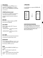
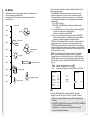
WHITE BAL
You can select one of four modes for white balance adjustment as follows:
Lights are generally denoted as color temperatures and expressed in
Kelvin (K) units.
The general light color temperatures are shown below.
- ATW1/ATW2(Auto-Tracing White Balance Mode): In these modes, the
color temperature is monitored continuously and thereby white balance is
set automatically. The following are the approximate supported color
temperature ranges in these modes.
ATW1 : 2500K ~ 9300K(✻1)
ATW2 : 2000K ~ 10000K(Mode recommended for sodium lighting)(✻2)
✻ 1. If the color temperature is out of this range in ATW1 mode, proper
white balance may not be obtained. In that case, select ATW2 mode.
✻ 2. In ATW2 mode, if one color is dominated in the shooted area, the
color can be displayed differently.
Therefore, select the mode which is appropriate for the environment.
- AWC(Auto-Tracing White Balance Control): In this mode, accurate white
balance is obtained by pressing [ENTER] while having a white paper in
front of the camera. White Balance data will be maintained after set it
once. AWC mode is best in locations where the color temperature of light
source is constant.
- MANU : If WHITE BAL menu is set to MANU mode, the user can set the
white Balance considering the current illumination. Select MANU item
and press [ENTER], the sub screen where you can select Manual White
Balance will be shown. Use the left/right keys to select 3200K, 5600K or
OFF(USER) mode in the PRESET menu.
10000K
9000K
Blue sky
Rainy
8000K
Cloudy
7000K
6000K
5000K
Partly Cloudy
Sunny
4000K
3000K
Fluorescent lamp
Halogen lamp
Tungsten lamp
1000K
Candlelight
- 3200K : Set color temperature to 3200K
- 5600K : Set color temperature to 5600K
- USER : Choose out a proper value from the RED and BLUE graph for
color and temperature setup.
(VIDEO SET)
2000K
E
IRIS
SHUTTER
AGC
WHITE BAL
DIS
FOCUS MODE
SPECIAL
EXIT
(AWB/MANU)
ALC...
OFF
LOW
MANU...
ON
ONEAF
...
QUIT
➜
Press
[Enter]
PRESET
3200K
RET
DIS
The DIS(Digital Image Stabilization) function compensates the camera
screen shaking incurred from vibration.
❈ It is recommended to deactivate the DIS function in the no vibration
environment.
❈ From VIDEO SET, if you set SHUTTER to between AUTO X2... and AUTO
X128... DIS will be displayed as “---“ (it can operate only in Off mode).
You can’t adjust the settings manually.
3-14
3-15
FOCUS MODE
EXIT
In the FOCUS MODE MENU, the Focus method can be set to ONEAF
(One Auto Focus), or MF(Manual Focus).
- ONEAF : In the ONEAF mode, it automatically sets the focus after the
PAN/TILT/ZOOM moves, and operates as the same in the MF mode if the
PAN/TILT/ZOOM does not move.
- MF
: In MANUAL FOCUS MODE the user adjusts the Focus manually.
Use the left/right keys to select ONEAF orMF in the FOCUS MODE menu.
It's the same as the EXIT function of the CAMERA SET menu.
3. PRESET
This is the menu that user sets the PAN/TILT location, Zoom/Focus, and
screen condition, so the camera can monitor the presetting area on
demand. A total of 128 presets are available.
(VIDEO SET)
E
IRIS
SHUTTER
AGC
WHITE BAL
DIS
FOCUS MODE
SPECIAL
EXIT
ALC...
OFF
OFF
ATW1
OFF
ONEAF
...
QUIT
❈ ONEAF can only be selected if SHUTTER is set to OFF, 1/100(1/120)
~1/10K, or AUTOX2...
In other modes (AUTOX4...~AUTOX128...), FOCUS mode will be
displayed as “MF“(the product automatically switches into MF mode).You
can ’t adjust the settings manually.
❈ ONEAF function may not possible withe types of objects listed below. For
such objects, focus manually.
- High intensity objects or objects illuminated with low lighting
- Obejects shot through wet or dirty glass
- Pictures that are a mixture of distant and nearby objects
- White alls and other single-color objects
- Venetian blinds and other horizontally striped objects
** MAIN MENU **
CAMERA SET...
VIDEO SET...
PRESET ...
ZONE SET...
AUTO SET...
ALARM SET...
OTHER SET...
SYSTEM INFO...
(PRESET MAP)
➜
Press
[Enter]
0
1
2
5
6
7
10 11 12
15 16 17
20 21 22
25 26 27
30 31 î
ID:PRESET 0
3
4
8
9
13 14
18 19
23 24
28 29
ï RET
PRESET NO.0
➜
Press
[Enter]
POSITION SET
PRESET ID
VIDEO SET
PRESET SPEED
DWELL TIME
IMAGE HOLD
...
ON...
OFF
8
3S
OFF
EXIT
QUIT
SPECIAL
In SPECIAL menu, you can directly adjust Y-LEVEL, C-LEVEL, and DETAIL
functions.
- Y-LEVEL : It is used to set the levels for the Sync signal and the entire
brightness signal of the video signal.
- C-LEVEL : It is used to set the levels for the Burst signal and the entire colour
signal of the video signal.
- DETAIL : Controls both horizontal and vertical distinction.
(VIDEO SET)
3-16
(SPECIAL)
IRIS
SHUTTER
AGC
WHITE BAL
DIS
FOCUS MODE
SPECIAL
ALC...
OFF
ON
ATW1
ON
ONEAF
...
EXIT
QUIT
➜
Press
[Enter]
Y-LEVEL
C-LEVEL
DETAIL
RET
(0)I-------(0)I-------(0)--I-
3-17
POSITION SET
4. ZONE SET
From "POSITION SET..." press [ENTER] to get into the PAN/TILT,
FOCUS/ZOOM SET screen
to set the PAN/TILT location and FOCUS/ZOOM condition then press
[ENTER] to return to a higher menu.
The ZONE SET menu includes the setup of ZONE DIRECTION, and
ZONE AREA.
PRESET ID
This is the ID set up function for each PRESET.
It can be set up to 12 characters using the left, right, up, and down keys.
The ID location can be set in the submenu of "LOCATION..."
VIDEO SET
** MAIN MENU **
CAMERA SET...
VIDEO SET...
PRESET...
ZONE SET...
AUTO SET...
ALARM SET...
OTHER SET...
SYSTEM INFO...
(ZONE SET)
➜
ZONE DIR SET
ZONE AREA SET
OFF
OFF
EXIT
QUIT
E
Press
[Enter]
This is the screen setting function for each PRESET.
Refer to the explanation under "VIDEO SET menu".
PRESET SPEED
This function sets up the speed of PAN or TILT by 8 steps from 1(SLOW)
to 8(FAST).
- PRESET SPEED 1 : Maximum PAN moving speed of 240°/sec
- PRESET SPEED 8 : Maximum PAN moving speed of 400°/sec
ZONE DIR SET
Press the [Enter] key in the “ZONE DIR SET ON…” mode to enter the
SET NORTH screen. MAP. Move PAN to set the SET NORTH position
and press [ENTER]. Based on the North position,the direction of N(North),
NE(North-East), E(East), SE(South-East), S(South), SW(South-West),
W(West), NW(North-West) is displayed whenever you move PAN.
DWELL TIME
This is a function setting for the DWELL TIME of the PRESET location in
"SCAN" motion. It can set DWELL TIME From 1 ~ 60 Sec.
(ZONE SET)
ZONE DIR SET
ZONE AREA SET
SET NORTH
ON...
OFF
IMAGE HOLD
Pauses the image when PRESET is in movement, If you set the IMAGE
HOLD menu to ON, the screen will be paused until PRESET finishes
moving.
➜
N
Press
[Enter]
EXIT
QUIT
EXIT
"QUIT" : Does not save the selected information and returns to a higher
menu.
"SAVE" : Do saves the selected information and returns to a higher menu.
"DEL" : Deletes the selected information and restores the DEFAULT.
Then returns to a higher menu.
3-18
3-19
ZONE AREA
LOCATION
Press [ENTER] to enter the ZONE AREA MAP screen from “ZONE
The “LOCATION...” menu designates the left/right LIMIT positions of
ZONE AREA. Enter the setup screen to move PAN, then select a start
position and press [ENTER]. Move PAN again
to select a end position and press [ENTER]. Now, ZONE AREA setup is
complete.
AREA SET...”. Select a ZONE AREA number from the ZONE AREA MAP
screen and press [ENTER] to enter the ZONE AREA setup screen.
ZONE AREA SET 0
(ZONE SET)
(ZONE AREA MAP)
ZONE DIR SET
ZONE AREA SET
OFF
ON...
0*
4
➜
1
5
2
6
3
7
SET START!
LOCATION
ZONE ID SET
ZONE ENABLE
...
...
ON
Press
[Enter]
EXIT
EXIT
➜
➜
Press
[Enter]
After P/R/Z
control, press
[ENTER]
E
QUIT
QUIT
SET END!
After PAN control,
press [ENTER] to
finish.
ZONE AREA SET 0
➜
Press
[Enter]
LOCATION
ZONE ID SET
ZONE ENABLE
EXIT
...
...
ON
QUIT
ZONE ID SET
This function is used to allocate as many as 12 IDs to each zone area.
Use Left , Right, UP, or DOWN for this purpose. You may select the ID
position from the additional menu of “LOCATION...”.
ZONE AREA ID 0
ZONE AREA SET 0
LOCATION
ZONE ID SET
ZONE ENABLE
...
...
ON
➜
Press
[Enter]
EXIT
A BCDEFGHI J K L
MNOPQRSTUVWX
Y Z 012345678 9
: ! - +✻ ( ) /
SP ï î SP
LOCATION...
RET
ZONE 0........
QUIT
ZONE ENABLE
This function turns on or off the ZONE AREA ID indication.
3-20
3-21
5. AUTO SET
SPEED
The AUTO SET menu includes AUTO PAN, PATTERN, and SCAN and it is
able to set up the AUTO PLAY motion.
This is a setting function for movement speed setup. It can be set from
STEP1 to STEP64.
DWELL TIME
AUTO PAN
This is a function for setting up the time to stay in the START to END position.
After selecting the locations of two points (PAN/TILT) of START and END,
it loops continuously in the set up SPEED. The number of AUTO PAN is
up to 4.
PATTERN
** MAIN MENU **
CAMERA SET...
VIDEO SET...
PRESET...
ZONE SET...
AUTO SET...
ALARM SET...
OTHER SET...
SYSTEM INFO...
This is a replay function so that the MANUAL functions such as PAN, TILT,
ZOOM, and FOCUS, IRIS are played for 2 minutes.
E
(AUTO SET)
➜
Press
[Enter]
AUTO PAN
PATTERN
SCAN
AUTO PLAY
1...
1...
1...
...
RET
❈ When the PATTERN is saved/executed, the PAN/TILT is operated with
PROPORTIONAL ON, TURBO OFF.
❈ If the SSC-1000 or SSC-2000 is used when uploading/downloading the
menu setup, reset the PATTERN because it may be different with the first
setting.
AUTO PAN 1
➜
POSITION SET
SPEED
DWELL TIME
...
22
3S
EXIT
QUIT
Press
[Enter]
POSITION SET
The menu “POSITION SET …” sets the Start / End position of AUTO PAN.
Return to the settings screen and set the desired START position for
PAN/TILT, and then press the [ENTER] key. And, set the END position for
the PAN/TILT. Press the [ENTER] key to finish the setup for AUTO PAN
Start/End positions.
3-22
3-23
** MAIN MENU **
CAMERA SET...
VIDEO SET...
PRESET...
ZONE SET...
AUTO SET...
ALARM SET...
OTHER SET...
SYSTEM INFO...
AUTO PLAY
(AUTO SET)
AUTO PAN
PATTERN
SCAN
AUTO PLAY
➜
Press
[Enter]
1...
1...
1...
...
➜
Press
[Enter]
RET
➜
PATTERN SET 1
SET START POSITION
AND ENTER
AUTO PLAY executes SCAN, AUTO PAN, PATTERN, and PRESET when there
is no camera action after AUTO RETURN finishes.
(AUTO PLAY SET)
(AUTO SET)
AUTO PAN
PATTERN
SCAN
AUTO PLAY
PATTERN SET 1
After
PATTERN
START
position setup,
press
[ENTER].
1...
1...
1...
...
RET
➜
AUTO RETURN 12HOUR
AUTO PLAY
SCAN
PLAY NUMBER 1
Press
[Enter]
E
EXIT
SAVE
AUTO RETURN
PATTERN can be set upto 3. Choose 1, 2, or 3 with the left or right key in the
"PATTERN SET" and press [ENTER] to get into the PATTERN set up screen. From
the moment "PATTERN 1 SET" is gone for 2 minutes, it memorizes the MANUAL
movements and after 2 minutes it will return to a higher menu. If you want to finish
set up before the 2-minutes ends, press [ENTER].
SCAN sets the direction of PRESET movement during “SCAN” operation. The
number of SCAN is up to 4 and each SCAN is able to allocate 32 PRESETs as a
maximum.
This function sets up the motion which will be repeatedly performed by
SCC-C6403P whenever the time set by AUTO RETURN elapses. It covers SCAN,
AUTO PAN, PATTERN, and PRESET setup.
This menu allocates a number to the motion set by AUTO PLAY. The numbers
range from 1 to 4 for SCAN AND AUTO PAN, 1 to 3 for PATTERN, and 0 to 127
for PRESET.
(SCAN MAP 1)
(AUTO SET)
RET
AUTO PLAY
PLAY NUMBER
SCAN
AUTO PAN
PATTERN
SCAN
AUTO PLAY
This menu sets up the time during which AUTO PLAY repeats.
1...
1...
1...
...
➜
Press
[Enter]
0*S 1*
2
5
6
7
10 11 12
15 16 17
20 21 22
25 26 27
30 31 î
EXIT
3
8
13
18
23
28
ï
4
9
14
19
24
29
SAVE
If you enter the SCAN SET screen, SCAN MAP will be displayed. Move the cursor
to the number marked * where PRESET is saved and press [ENTER] and
S will appear and a PRESET will be included in SCAN.
3-24
3-25
AUTO SET
6. ALARM SET
It consists of 4 ALARM INPUTs and 3 ALARM OUTs.It can sense an
ALARM input from exterior SENSORs and it performs with PRESET or
PATTERN function and outputs the ALARM OUT signals.
Alarm operation time depends on the Preset Dwell time corresponding to
the alarm and whether AUTO is involved.
** MAIN MENU **
CAMERA SET...
VIDEO SET...
PRESET...
ZONE SET...
AUTO SET...
ALARM SET...
OTHER SET...
SYSTEM INFO...
( ALARM SET)
➜
Press
[Enter]
ALARM PRIORITY SET ...
ALARM IN SET..
ALARM OUT SET..
AUTO SET..
AUX OUT CONTROL..
This menu designates what to do at the time of ALARM input. Once an
alarm is given, the camera will shortly move to the PRESET position
corresponding to the respective alarm as follows.
PRESET1 to ALARM1~4
PRESET5 to MOTION
After DWELL TIME at a PRESET position, PATTERN or SCAN will be in
action according to the AUTO SET setup.
Setup of OFF/PATTERN 1~3/HALF1/HALF2/FULL/SCAN1~4 is available.
OFF dues not perform PATTERN or SCAN after moved to PRESET and
each menu has its own function as follows.
PATTERN 1~3 : Preset PATTERN action,
HALF1 : Continuous operation of PATTERN1 + PATTERN2
HALF2 : Continuous operation of PATTERN2 + PATTERN3
FULL : Continuous operation of all the aboves
SCAN 1~4 : Scanning as set
E
RET
AUX OUT CONTROL
ALARM PRIORITY SET
This sets the priority of the 4 ALARM inputs so ALARM can work
corresponding to the priority.
The priority of the DEFAULT is ALARM1, ALARM2, ALARM3, ALARM4.
If the ALARM is working at the same time and the priority is the same, it
will operate according to the DEFAULT priority. While the ALARM is
working, it cannot detect MOTION.
ALARM IN SET
7. OTHER SET
This sets the input TYPE to "NO" (Normal Open), "NC" (Normal Close), or
"OFF" depending on the features of the SENSOR connected.
PROPORTIONAL P/T
ALARM OUT SET
Each ALARM input corresponds to one of the 3 ALARM OUT.
3-26
This sets the ALARM OUT motion to continue or act only when the
ALARM is working.
If it is set to OFF the ALARM OUT motion will operate only when the
ALARM is working.
(Active "Low"), and if it's set to ON, the ALARM OUT will always operate
regardless of the ALARM.
This function controls the PAN/TILT speed to the ZOOM magnification
ratio during the manual operation of PAN/TILT. If you set
PROPORTIONAL P/T to ON, the PAN/TILT speed will increase in the
ZOOM WIDE mode and decrease in the ZOON TELE mode even in the
same manual operation.
3-27
TURBO P/T
This function doubles up the speed of PAN/TILT movement by manual
operation of PAN/TILT. The speed may go up to 180°/sec(PAN).
AUTO CAL
This function turns on or off Auto Calibration. SCC-C6403P has the Auto
Calibration function to improve the precision of LENS and PAN/TILT
motor. You may set to OFF/6H/12H/18H/24H. Without user’s key input for
the time designated by the user, A.C will appear on the screen while
initializing LENS and PAN/TILT.
AUTO FLIP
When TILT is set to a 90° limit using the joystick, PAN automatically
rotates by 180°
enabling you to see up to the Tilt area on the opposite side .
You can obtain an extended effect with the 180° operational range of the
TILT feature.
CAM RESET
CAM RESET clears all the settings made so far and restores the factory
default settings.
"CAMERA RESET?" message appears when you select CAM RESET.
Select "CANCEL" to return to the menu setup display or select OK to
restore the factory default settings.
❈ Be careful when performing a CAM RESET operation, as it deletes all
setup values.
(PASSWORD)
(OTHER SET)
PROPORTIONAL P/T
TURBO P/T
AUTO CAL.
AUTO FLIP
CAM RESET
LANGUAGE
PASSWORD
EXIT
ON
OFF
OFF
ON
...
ENGLISH
ON...
➜
0
1
2
3
4
5
6
7
8
9
Press
[Enter]
✽✽✽✽
✽✽✽✽
RET
QUIT
Press UP/DOWN/LEFT/RIGHT key to locate the cursor on a number and
press [ENTER] for password setup. After you finish inputting the 4 digits
password and the 2nd row of the 4 digits PASSWORD input screen, input
the selected password again for reassurance.
If correct, the cursor will move to RET.
Press [ENTER] at RET, and the selected password will be saved,
returning to the OTHER SET screen.
Default password is 0123.
E
8. SYSTEM INFO
This menu allows you to check S/W version, communication protocol,
baud rate, and address of SCC-C6403P.
** MAIN MENU **
CAMERA SET...
VIDEO SET...
PRESET...
ZONE SET...
AUTO SET...
ALARM SET...
OTHER SET...
SYSTEM INFO...
( SYSTEM INFO)
➜
Press
[Enter]
ALARM VER.
MOTOR VER.
CAMERA VER.
EEPROM VER.
PROTOCOL
COMM. TYPE
BAUD RATE
ADDRESS
SERIAL NO.
RET
V1.000
V1.000
V1.000
V1.000
SAMSUNG
RS-485,HALF
9600
0
000000000000000
LANGUAGE
This function selects a language for MENU setup. Press LEFT/RIGHT key to
choose English, French, German, Spanish or Italian and the selected
language will be applied to the full screen.
PASSWORD
This function selects or cancels the MENU setup password. Press
[ENTER] at the state of PASSWORD ON..., and the following screen will
appear for password setup.
3-28
3-29
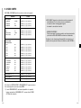
9. SHORT KEYS
SSC-1000 or SSC-2000 Controller supports the following short keys.
Function
Key
❈ SCC-C6403P has two FANs inside for preventing overheating.
CAMERA SET…
COLOR/BW
COLOR
[PRESET] + [1] + [2] + [8] + [Enter]
COLOR/BW
BW
[PRESET] + [1] + [2] + [9] + [Enter]
COLOR/BW
AUTO
[PRESET] + [1] + [3] + [0] + [Enter]
VIDEO SET…
IRIS
ALC
[PRESET] + [1] + [3] + [2] + [Enter]
FOCUS MODE
MF
[PRESET] + [1] + [3] + [4] + [Enter]
FOUCS MODE
ONEAF
[PRESET] + [1] + [3] + [5] + [Enter]
OUT1
ON
[PRESET] + [1] + [3] + [6] + [Enter]
OUT1
OFF
[PRESET] + [1] + [3] + [7] + [Enter]
OUT2
ON
[PRESET] + [1] + [3] + [8] + [Enter]
OUT2
OFF
[PRESET] + [1] + [3] + [9] + [Enter]
OUT3
ON
[PRESET] + [1] + [4] + [0] + [Enter]
OUT3
OFF
[PRESET] + [1] + [4] + [1] + [Enter]
PROPORTIONAL P/T
ON
[PRESET] + [1] + [4] + [2] + [Enter]
PROPORTIONAL P/T
OFF
[PRESET] + [1] + [4] + [3] + [Enter]
TURBO P/T
ON
[PRESET] + [1] + [4] + [4] + [Enter]
TURBO P/T
OFF
[PRESET] + [1] + [4] + [5] + [Enter]
AUTO FLIP
ON
[PRESET] + [1] + [4] + [6] + [Enter]
AUTO FLIP
OFF
[PRESET] + [1] + [4] + [7] + [Enter]
If FAN doesn't work properly, messages below will be displayed.
In those case, replace the FAN.
- ALARM FAN ERROR !
: This message is displayed when the FAN which is located bottom of
SCC-C6403P does not work properly.
E
Contact your nearest Samsung Electronics Service Center or designated
retailer before replacing the FAN.
ALARM SET…
AUX OUT CONTROL…
OTHER SET…
AUTO RETURN *1)
[PRESET] + [1] + [4] + [8] + [Enter]
AUTO CAL.
[PRESET] + [1] + [4] + [9] + [Enter]
CAM RESET
[PRESET] + [1] + [5] + [0] + [Enter]
Other keys than AUTO CAL. and AUTO RETURN, upon execution, shall
be applied to the MENU setup process.
1) The use of AUTO RETURN will be available only when the function
equivalent to AUTO PLAY, a sub menu of AUTO SET has been built in.
3-30
3-31
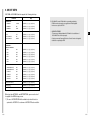
Product specifications
Cautions
SCC-C6403P
NO
Items
1
Product Type
2
Power Input
3
Power Consumption
4
Contents
• The copyright of the manual belongs to Samsung Electronics Co., Ltd.
- AC 24 ± 10% (50Hz ± 0.3Hz)
• Without the permission of Samsung Electronics it cannot be reproduced
electronically, mechanically, audibly, or by any other method.
- 18W
Broadcasting Type - PAL STANDARD COLOR SYSTEM
5
Image Device
6
Effective Pixels
- 752(H) X 582(V)
7
Scanning Mode
- 625 Lines, 2:1 Interlace
8
Scanning line
Frequency
9
Synchronization Mode
10
Resolution
- 480 TV LINES
11
S/N Ratio
- 50dB (AGC OFF)
12
Remark
- Zoom lens single body SmartDome CAMERA
Min. Object Illumination
- 1/4 inch 410K IT Type S-HAD CCD
• This manual will be modified according to product enhancements.
- Horizontal : 15,625 Hz(INT) / 15,625 Hz(L/L)
- Vertical : 50 Hz(INT) / 50 Hz(L/L)
Correct Disposal of This Product
(Waste Electrical & Electronic Equipment)
- INT/LINE LOCK
(Applicable in the European Union and other European countries with
separate collection systems)
- COLOR : 0.3 Lux (30 IRE : Sense-Upx4)
0.01 Lux (30 IRE : Sense-Up x128)
- B/W : 0.03 Lux (30 IRE : Sense-Upx4)
0.001 Lux (30 IRE : Sense-Up x128)
This marking shown on the product or its literature, indicates that it should not be
disposed with other household wastes at the end of its working life. To prevent
possible harm to the environment or human health from uncontrolled waste
disposal, please separate this from other types of wastes and recycle it responsibly
to promote the sustainable reuse of material resources.
13 Color Temperature - ATW1/ATW2/AWC/MANUAL MODE
(3200K, 5600K, R/B GAIN Court)
14
Signal Output
15
Lens
16
PAN Function
- PAN range : 350° Non-Endless
- Preset Pan Speed : max 400°/sec
- Manual Pan Speed : 0.1°~180°/sec (64step)
17
TILT Function
- TILT range : 0°~90°
- Preset TILT Speed : max 200°/sec
- Manual TILT Speed : 0.1°~90°/sec (64step)
18
REMOTE
CONTROL
- ZOOM(TELE/WIDE), FOCUS(NEAR/FAR),
IRIS(OPEN/CLOSE), PAN/TILT, MENU
RS-485 HALF/FULL Duplex, RS-422
- COMPOSITE VIDEO OUT : 1.0Vp-p 75ohms/BNC
- one body; 32x Zoom lens
- Focal Length : 3.55 to 113 mm
- Aperture : F3.8(Wide), F4.7(Tele)
- Auto Focus
Household users should contact either the retailer where they purchased this
product, or their local government office, for details of where and how they can take
this item for environmentally safe recycling.
Business users should contact their supplier and check the terms and conditions of
the purchase contract. This product should not be mixed with other commercial
wastes for disposal.
- Alarm Inputs : 4 IN(5mA Sink)
- Alarm Outputs : 3 OUT (Open collector : 2
DC24V 40mA Max, Relay : 1, NO, NC, COM
2A 30VDC, 0.5A 125VAC Max)
20 Operation Temperature - 10°… ~ +50°…
21 Operation Humidity - ~90%
19
ALARM
22
SIZE
23
Weight
- DOME : 147 (ø),
- Outline : 159.6(ø) X 177(H)
- 1.8Kg
24 Lives of Main Parts - FAN
3-32
4.5 Years
SmartDome Kamera
SCC-C6403P
Benutzerhandbuch
Part : AB68-00571A(00)
D
Sicherheitshinweise
Ziel dieser Informationen ist es, den ordnungsgemäßen Gebrauch dieses
Geräts sicherzustellen und dadurch Gefahren oder Sachbeschädigungen zu
vermeiden. Bitte befolgen Sie alle Anweisungen.
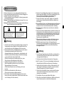
* Die Sicherheitshinweise sind mit “Warnung” und “Achtung” gekennzeichnet,
wie nachfolgend angegeben:
Warnung: Die Nichtbeachtung eines Warnhinweises kann zum Tode oder zu
schweren Verletzungen führen.
Achtung: Die Nichtbeachtung eines mit Achtung gekennzeichneten Hinweises
kann zu Verletzungen und Sachschaden führen.
Die mit Warnung gekennzeichneten
Informationen weisen auf eine mögliche
Gefahr hin, die zum Tode oder zu
schweren Verletzungen führen kann.
Die mit Achtung gekennzeichneten
Informationen weisen auf eine mögliche
Gefahr hin, die zu Verletzungen oder
Sachschaden führen kann.
Warnung
1. Achten Sie darauf, daß Sie nur den mitgelieferten Adapter verwenden. Die
Verwendung eines anderen Adapters als des mitgelieferten kann Feuer,
einen Stromschlag oder die Beschädigung des Geräts verursachen.
2. Beim Anschließen der Netz- und Signalkabel müssen zuvor die externen
Anschlussbuchsen überprüft werden. Schließen Sie die
Alarmsignalkabeladern an die Alarmanschlüsse, den Netzadapter an die
Netzsteckdose und den Gleichstromadapter an den Gleichstromeingang
an, und achten Sie dabei auf die richtige Polarität.
(Ein falscher Anschluss an das Stromnetz kann zu Feuer, einem
Stromschlag oder zur Beschädigung des Geräts führen.)
3. Schließen Sie nicht mehrere Kameras an einen Adapter an.
(Wird die Kapazität überschritten, kann es zu einer anormalen
Wärmeentwicklung oder Feuer kommen.)
(Fällt die Kamera herunter, kann es zur Verletzung von Personen
kommen.)
4. Stecken Sie das Netzkabel fest in die Steckdose ein.
(Ein loser Anschluss kann einen Brand verursachen.)
5. Bei der Wand- oder Deckeninstallation ist darauf zu achten, dass die
Kamera sicher und fest angebracht wird. (Fällt die Kamera herunter, kann
es zur Verletzung von Personen kommen.)
6. Platzieren Sie keine leitfähigen Gegenstände (wie z. B. Schraubenzieher,
Münzen und metallene Objekte) oder mit Wasser gefüllte Behälter auf der
Kamera. (Dies kann zur Verletzung von Personen durch Feuer,
Stromschlag oder herunterfallende Gegenstände führen.)
7. Die Kamera darf nicht an einem feuchten, staubigen oder rußigen Ort
installiert werden. (Andernfalls besteht die Gefahr eines Brandes oder
Stromschlags.)
8. Bei ungewöhnlicher Geruchs- oder Rauchentwicklung muss der Betrieb des
Geräts sofort beendet werden. Ziehen Sie unverzüglich den Netzstecker
und setzen Sie sich mit einem Kundendienstzentrum in Verbindung.
(Die Weiterbenutzung des Geräts kann zu einem Brand oder elektrischen
Schlag führen.)
9. Wenn das Gerät nicht einwandfrei funktioniert, wenden Sie sich bitte an die
Verkaufsstelle, in der Sie das Gerät erworben haben, oder an das nächste
Kundendienstzentrum. Das Gerät darf niemals und in keiner Weise selbst
zerlegt oder modifiziert werden. (SAMSUNG übernimmt keine Haftung für
Probleme, die durch unbefugte Abänderungen oder einen
Reparaturversuch herbeigeführt sind.)
10. Wasser darf beim Reinigen niemals direkt auf die Geräteteile gelangen.
(Andernfalls besteht die Gefahr eines Brandes oder Stromschlags.)
Die Oberfläche kann mit einem trockenen Tuch abgewischt werden.
Verwenden Sie keine Reinigungsmittel oder chemischen Reiniger, da sich
durch solche Mittel die Farbe ablösen und der Oberflächenüberzug
beschädigt werden kann.
Achtung
1. Lassen Sie keine Gegenstände auf das Gerät fallen, und schützen Sie es
vor starken Stößen. Setzen Sie die Kamera keinen starken Vibrationen
oder magnetischen Störfeldern aus.
2. Die Kamera darf nicht an Orten mit hohen bzw. tiefen Temperaturen
(über 50 °C und unter -10 °C) oder hoher Luftfeuchtigkeit installiert werden.
(Andernfalls besteht die Gefahr eines Brandes oder Stromschlags.)
3. Installieren Sie das Gerät nicht in der Nähe von Wärmequellen, wie z. B.
einem Heizgerät oder Heizkörper, und an Orten, an denen es direktem
Sonnenlicht ausgesetzt ist. (Hier besteht Feuergefahr.)
4. Wenn Sie die bereits installierte Kamera an einen anderen Ort verlegen
wollen, achten Sie darauf, die Kamera auszuschalten, bevor Sie sie
abnehmen oder neu installieren.
5. Die Installation sollte an einer gut belüfteten Stelle erfolgen.
6. Ziehen Sie bei einem Gewitter den Netzstecker. (Wird dies nicht beachtet,
kann ein Brand verursacht oder das Gerät beschädigt werden.)
D
Vor Inbetriebnahme
Dies ist ein grundlegendes Benutzerhandbuch für Nutzer der
Geschwindigk- Dome Kamera SCC-C6403P. Es enthält alle
notwendigen Hinweise für den Betrieb der SCC-C6403P von der
einfachen Einführung der Bedienungselemente der
SCC-C6403P und deren Funktionen bis hin zu
Installationsmethoden im Setup-Menü.
Wir empfehlen allen Nutzern der SCC-C6403P, dieses Handbuch
vor dem Gebrauch zu lesen, sowohl den erfahrenen Nutzern, die
ähnliche Kameras bereits verwendet haben, als auch den
gewöhnlichen Nutzern.
Das am häufigsten benutzte Merkmal der Geschwindigk-Dome
Kamera SCC-C6403P ist das SCC-C6403P Setup-Menü.
Das SCC-C6403P Setup-Menü wird im Kapitel 3 : Überblick über
das Setup-Menü genau erklärt.
Es ist am sinnvollsten, das Handbuch von vorn bis hinten zu
lesen, aber für diejenigen, die nur aktuell benötigte Auszüge lesen
wollen, sind hier die Kapitelzusammenfassungen.
"Kapitel 1 : Überblick über die SCC-C6403P” enthält eine kurze
Einführung in die Geschwindigk-Dome Kamera SCC-C6403P, ihre
Einzelteile und Funktionen und Schaltereinstellungen.
"Kapitel 2 : Installation der Geschwindigk-Dome Kamera
SCC-C6403P” erklärt die Installationsanweisung der
SCC-C6403P und informiert über Vorbereitungen und
Randbedingungen der Inbetriebnahme.
"Kapitel 3 : Überblick über das Setup-Menü” erläutert die
Struktur des Setup-Menüs der SCC-C6403P einschließlich einer
ausführlichen Erklärung der verfügbaren Funktionen in jedem
Untermenü.
"Anhang A : Technische Daten der Geschwindigk-Dome
Kamera SCC-C6403P” enthält Produktspezifikationen der
SCC-C6403P in tabellarischer Übersicht.
1-1
Inhaltsverzeichnis
Vor Inbetriebnahme.......................................................................................................1-1
Kapitel 1 Überblick über die SCC-C6403P.................................................................1-4
Einführung in die SCC-C6403P.....................................................................1-5
Steuerungselemente…..................................................................................1-6
ADAPTERANSCHLUSS................................................................................1-8
ERSTEINSTELLUNG ....................................................................................1-9
Einstellung der RS-422A/RS-485 Abschlüsse.............................................1-10
Kapitel 2 Installation der SCC-C6403P ......................................................................2-1
D
Vor der Installation.........................................................................................2-2
Vorbereitung der Kabel..................................................................................2-3
Kabelanschlüsse ...........................................................................................2-4
Installation der SCC-C6403P ........................................................................2-5
Installation der Kamera..................................................................................2-8
Kapitel 3 Überblick über das Setup-Menü..................................................................3-1
Aufbau des Setup Menüs ..............................................................................3-2
1. KAMERA PROG .......................................................................................3-4
- KAMERA ID ...........................................................................................3-4
- V-SYNC..................................................................................................3-5
- FARBE/S/W ...........................................................................................3-6
- AKTIVITAET...........................................................................................3-7
- ZOOM GESCH.......................................................................................3-8
- DIGITAL ZOOM .....................................................................................3-9
- DISPLAY ZOOM ....................................................................................3-9
- DISPLAY P/T .........................................................................................3-9
- AUSGANG ...........................................................................................3-10
2. VIDEO PROG-Menü ...............................................................................3-10
- BLENDE...............................................................................................3-10
- ALC ...................................................................................................3-10
- BLC .................................................................................................3-10
- MANU ...............................................................................................3-11
- SHUTTER ............................................................................................3-12
- FLIMMERFREI ...............................................................................3-12
- AGC .....................................................................................................3-13
- BEWEGUNG........................................................................................3-13
- WEISSABGL ........................................................................................3-14
- DIS .......................................................................................................3-15
- FOKUS MODE .....................................................................................3-16
- SPEZIAL ..............................................................................................3-16
- AUSGANG ...........................................................................................3-17
3. PRESET ..................................................................................................3-17
- POSITION PROG................................................................................3-18
- PRESET ID..........................................................................................3-18
- VIDEO PROG ......................................................................................3-18
- PRESET TEMPO.................................................................................3-18
- SCHWELLZEIT....................................................................................3-18
- BILD HALTEN......................................................................................3-18
- AUSGANG...........................................................................................3-18
1-2
4. ZONE PROG ...........................................................................................3-19
- RICHTUNG SETZEN...........................................................................3-19
- ZONE GESETZT .................................................................................3-20
- POSITION.........................................................................................3-21
- ZONE ID SETZEN ............................................................................3-21
- ZONE AKTIVIEREN .........................................................................3-21
5. AUTO PROG ...........................................................................................3-22
- AUTO PAN ..........................................................................................3-22
- POSITIONS PROG...........................................................................3-22
- GESCHWINDIGK .............................................................................3-23
- SCHWELLZEIT.................................................................................3-23
- PATTERN ............................................................................................3-23
- SCAN...................................................................................................3-24
- AUTO MODUS ....................................................................................3-25
- AUTO ZURÜCK................................................................................3-25
- AUTO MODUS .................................................................................3-25
- FUNKTIONSNUMMER.....................................................................3-25
6. ALARM PROG.........................................................................................3-26
- ALARM PRIORITÄT PROG.................................................................3-26
- ALARM ENT PROG.............................................................................3-26
- ALARM AUS PROG ............................................................................3-26
- AUTO PROG .......................................................................................3-27
- AUX AUS KONTROLLE ......................................................................3-27
7. WEITERE PROG.....................................................................................3-27
- PROPORT. P/T ...................................................................................3-27
- TURBO P/T..........................................................................................3-28
- AUTOKALIBRIER. ...............................................................................3-28
- AUTO FLIP ..........................................................................................3-28
- KAM RESET ........................................................................................3-28
- SPRACHE ..........................................................................................3-28
- PASSWORT ........................................................................................3-28
8. SYSTEM INFO ........................................................................................3-29
9. Kurztasten ...............................................................................................3-30
Kapitel 1 : Überblick über die SCC-C6403P
In diesem Kapitel werden die Funktionen der SCC-C6403P
kurz beschrieben. Die Hauptfunktionen, Steuerungselemente
und Schaltereinstellungen werden erläutert.
D
Technische Daten ................................................................................................... 3-32
1-3
1-4
Einführung in die SCC-C6403P
SCC-C6403P ist Smart Dome Kamera mit Zoom Objektiv, die in
den Banken oder Firmen mit der Verbindung von CCTV optimale
Überwachungsfunktion anbietet.
Steuerungselemente
Vorderseite
D
Die Geschwindigk-Dome Kamera SCC-C6403P ist eine
hochqualitative Überwachungskamera mit x32 Zoom-Objektiv und
einem digitalen 10- fach Zoom. Sie kann scharfe Kamerabilder bis
zu 320-fach heranzoomen.
SCC-C6403P ist
- FARBE/S/W Funktion, die Kamera schaltet bei niedriger
Beleuchtungsstärke automatisch in den Schwarz/Weiß Modus
bzw. bei ausreichender Beleuchtung wieder in den Farb Modus.
- Weißabgleich Funktion, die je nach Beleuchtung das Bild natürlich
aussehen lässt,
- Gegenlicht Korrektur Funktion, die bei Spotlight oder sehr hellen
Beleuchtung das Gegenlicht perfekt korrigiert und das Objekt
dunkel aussehen lässt,
- Auto Fokus Funktion Automatische Bildschärfekorektur
- PAN/TILT für unkomplizierten Betrieb.
Die Geschwindigk-Dome Kamera SCC-C6403P besitzt eine
Alarmfunktion für Gefahrensituationen und ist eine in beliebige
Richtungen bewegliche Kamera. ZOOM-IN und ZOOM-OUTFunktionen können ferngesteuert werden.
1-5
1-6
ADAPTERANSCHLUSS
Rückseite
SCC-C6403P Anschlussfeld
AC 24V
OUT
POWER
D
AC 24V
OUT
POWER
1-7
1-8
ERSTEINSTELLUNG
Einstellung der RS-422A/RS-485 Abschlüsse
KAMERA ADRESSE EINSTELLEN
KAMERA ADRESSE einstellen mit SW701, SW702, SW703.
ADRESSEN Einstellung von 0~255 ist möglich und die 100-stellige Zahl
wird mit SW701, die 10-stellige Zahl mit SW702, 1-stellige Zahl mit
SW703 eingestellt.
Z.B) KAMERA ADDR: Wenn es Adresse 1 ist, wird wie folgt eingestellt.
SW701
SW703
SW702
Einstellung des Kommunikationsprotokolls.
Benutzen Sie die Ziffern 1 bis 4 PINs von SW704, um das
Kommunikationsprotokoll einzustellen.
PIN
Comp
PIN1
PIN2
PIN3
PIN4
A
AUS
AUS
AUS
AUS
B
EIN
AUS
AUS
AUS
C
AUS
EIN
AUS
AUS
D
EIN
EIN
AUS
AUS
E
AUS
AUS
EIN
AUS
F
EIN
AUS
EIN
AUS
G
AUS
EIN
EIN
AUS
H
EIN
EIN
EIN
AUS
I
AUS
AUS
AUS
EIN
J
EIN
AUS
AUS
EIN
K
AUS
EIN
AUS
EIN
L
EIN
EIN
AUS
EIN
M
AUS
AUS
EIN
EIN
N
EIN
AUS
EIN
EIN
O
AUS
EIN
EIN
EIN
P
EIN
EIN
EIN
EIN
1
2
Wenn der Controller und RS-422A/RS-485 Buchsen verbunden sind,
sollte, wie in der Übersicht dargestellt, der Abschluss entsprechend der
Impedanz (des Scheinwiderstandes) des jeweiligen Übertragungsweges
eingestellt werden, um Signale bei großen Entfernungen durch Kontrolle
der Reflektionen auf der Leitung auszugleichen.
Aufteilung
D
n < 32
A : SAMSUNG HALB
B : SAMSUNG VOLL
Termination
SW1-EIN
SEE INSTRUCTION
MANUAL
SIEHE
BEDIENUNGSANLEITUNG
ON 1 2 3 4 5 6 7 8
SW704
(x100)
(x10)
(x1)
<RS-485 Halbduplex-Betriebsart>
SW701 SW702 SW703
Abschluss: Verwenden Sie PIN-Nummer 1 und 2, Schalten auf EIN bedeutet
Abschluss.
n < 32
(UNTERSEITE)
Aufteilung
Division
SW1-EIN
SW2-EIN
Einstellung der Baudrate
Verwenden Sie PIN 5 und 6 von SW704.
1
2
3
4
5
6
7
<RS-422A/RS-485 Vollduplex-Betriebsart>
8
EIN
AUS
SW 704
PIN 5
PIN 6
4800 BPS
EIN
EIN
9600 BPS
AUS
EIN
19200 BPS
EIN
AUS
38400 BPS
AUS
AUS
BAUD RATE
1-9
Die Werkseinstellung beträgt 9600 bps.
❈ Es kann ein Kommunikationsfehler auftreten, wenn Sie mehrere Kameras
mit derselben Netzwerkadresse anschließen.
1-10
Vor der Installation
Überprüfung des Verpackungsinhalt
Kapitel 2 : Installation der SCC-C6403P
Überprüfen Sie bitte, ob alle unten aufgelisteten Teile in der Packung
enthalten sind
D
In diesem Kapitel wird zunächst der Lieferumfang der SCC-C6403P
überprüft und ein zur Stromversorgung geeigneter Netzadapter
vorbereitet.
(Leistungsaufnahme: 18W; Spannung: 24V Wechselstrom, 1,5 A).
Im Anschluss daran werden die Kabelanschlüsse und die Installation
der SCC-C6403P beschrieben.
SCC-C6403
Haltewinkel
Bedienerhan
dbuch
AC 24V
OUT
POWER
Schrauben
Kamerahalterung
Abdeckungsteile
2-1
2-2
Vorbereitung der Kabel
Um die Geschwindigk-Dome Kamera SCC-C6403P zu installieren und in
Betrieb zu nehmen, werden folgende Kabel benötigt:
Kabelanschlüsse
1. Verbinden Sie ein Ende des
BNC-Video-Kabels mit dem
Videoausgang (VIDEO OUT).
Netzanschlusskabel
Das Kabel, das an den Netzeingang der SCC-C6403P angeschlossen
wird, hat eine Nennspannung von 24V Wechselstrom, 1,5A.
Vor Benutzung des Kabels sollte die Nennspannung überprüft werden.
2. Verbinden Sie dann das andere
Ende mit dem Videoeingang des
Monitors.
D
3. Schließen Sie nun das
Netzanschlusskabel an.
Verwenden Sie einen
Schraubenzieher, um ein Ende
der beiden Leitungen des
Netzteils mit dem
Spannungseingang der
Geschwindigk-Dome Kamera
SCC-C6403P zu verbinden.
Video-Kabel
Das Video-Kabel ist ein BNC-Kabel. Es verbindet den Videoausgang der
Geschwindigk-Dome Kamera SCC-C6403P mit dem Videoeingang des
Monitors.
4. Stellen Sie den Schalter am Netzteil auf die verwendete Spannung ein.
Stecken Sie dann den Netzteilstecker in die Steckdose.
5. Verbinden Sie die Fernsteuerung
der Geschwindigk-Dome Kamera
SCC-C6403P mit der
externen Steuerung.
Controller
2-3
ANSCHLUSSFELD
2-4
Installation der SCC-C6403P
Sicherheitshinweise für die Installation
1) Vergewissern Sie sich, dass die Installationsstelle mindestens das
vierfache Eigengewicht der SCC-C6403P SmartDome-Kamera
einschließlich Zubehör tragen kann.
2) Installieren Sie das Gerät an einer Stelle, an der der Abstand zwischen
Deckenplatte und Decke mindestens 18 cm beträgt.
3) Benutzen Sie die mitgelieferten Schrauben zur Befestigung der Kamera
an der Halterung.
4) Im Installationsbereich dürfen sich keine Personen aufhalten, da sie
durch herabfallende Gegenstände gefährdet werden können.
Außerdem sollten Sie Gegenstände, die nicht beschädigt werden
dürfen, vor der Installation an einen sicheren Ort bringen.
3) GEHÄUSE für den INNENBEREICH (SHG-120)
Dieses Gehäuse eignet sich zur Installation der SmartDome-Kamera
an einer Wand in einem Innenraum.
D
Separat erhältliches Zubehör für die Installation
Die folgenden Produkte erleichtern die Installation an verschiedenen
Installationsorten.
1) DECKENHALTERUNG (SBR-100DCM)
Diese Halterung wird zur Installation
der SmartDome Kamera an einer
abgehängten Decke verwendet.
4) GEHÄUSE für den AUSSENBEREICH (SHG-220)
Dieses Gehäuse eignet sich zur Installation der SmartDome-Kamera
an einer Wand oder Decke im Außenbereich.
2) WANDHALTERUNG (SADT-100WM)
Diese Halterung wird benutzt, um das
SmartDome-Kameragehäuse für
den Innen- oder Außenbereich an einer
Wand zu installieren.
❈ Zum Anbringen des Outdoor-Gehäuses entfernen Sie die
transparente Schutzhülle vom Kameragehäuse.
2-5
2-6
Installation der Kamera
5) DECKENHALTERUNG (SADT-100CM)
Diese Halterung wird bei der Installation des SmartDomeKameragehäuses für innen oder außen an einer Betondecke
verwendet.
1. [Bild 1] Befestigen Sie den Aufbau
an der Decke.
(Beachten Sie bei der Installation
die Höhe des Aufbaus.)
* Eingebaut vom Hersteller.
D
[Bild 1]
Länge des
Deckenlochs
2. Machen Sie an der Stelle, wo die Kamera installiert werden soll, ein
Loch in die Decke.
(Das Loch sollte etwa einen Durchmesser von 185 mm haben.)
6) MASTHALTERUNG (SADT-100PM)
3. [Bild 2] Befestigen Sie den
Haltewinkel (BRKT-ANCHOR)
an der Decke und schrauben
Sie sie mit 4 Schrauben fest.
Diese Halterung eignet sich zur Installation der WANDHALTERUNG
(SADT-100WM) an einem Masten mit einem Durchmesser von über 8 cm.
[Bild 2]
4. [Bild 3, 4] Verbinden Sie die verschiedenen Kabel mit dem
Kameraadapter (siehe Seite 2-4)
[Bild 3]
2-7
[Bild 4]
2-8
5. [Bild 5] Stecken Sie den
Kameradapter in den Haltewinkel
und schrauben Sie ihn mit 4
Befestigungsschrauben
(PH M4X8) fest.
6. Ziehen Sie die Sicherheit Leitung
vom Case körper und bauen Sie
zum Halter von HOLDER-KAMERA
zusammen.
Kapitel 3: Überblick über das Setup-Menü
[Bild 5]
[Bild 6]
Dieses Kapitel gibt einen Überblick über das Setup-Menü der
Geschwindigk-Dome Kamera SCC-C6403P. Zuerst wird die
allgemeine Struktur des Setup-Menüs erläutert und dann die
Funktionen der einzelnen Menüs.
7. [Bild 7] Stecken Sie passend auf
die 3 Löcher an der Rückseite der
Kamera das Verbindungsstück
und drehen sie es um etwa
15Grad nach links.
(Überprüfen Sie am Geräusch, ob
das Verbindungsteil eingerastet ist
und der Hebelverschluss hält.)
* Verwenden Sie Schrauben
(BH M3XL8), um die Kamera und
den Adapter zu befestigen.
8. [Bild 8] Montieren Sie den
Gehäusering auf den DOME.
2-9
D
[Bild 7]
[Bild 8]
3-1
Aufbau des Setup Menüs
ALARM PROG
KAMERA PROG
KAMERA ID
V-SYNC
FARBE/S/W
AKTIVITAET
ZOOM GESCH
DIGITAL ZOOM
DISPLAY ZOOM
DISPLAY P/T
AUSGANG
EIN.../AUS
INT/LINIE...
FARBE.../S/W.../AUTO...
EIN.../AUS
1/2/3/4
AUS/X2 ~ X10
AUS/EIN
AUS/EIN
VERL/SICHERN/PRESET
ALARM PRIORITÄT PROG
ALARM1~4
AUSGANG
1~4
VERL/SICHERN
ALARM EIN PROG
ALARM1~4
AUSGANG
NO/NC/AUS
VERL/SICHERN
ALARM AUS PROG
ALARM1~4
AKTIVITAET
AUSGANG
1~3
1~3
VERL/SICHERN
AUTO PROG
VIDEO PROG
BLENDE
SHUTTER
AGC/BEWEGUNG
AUSGANG
ALC.../MANU...
AUS/1/100(1/120)~1/10K/AUTOX2...~X128...
AUS/WENIG/HOCH(AGC)S.LANGS/LANGS/
NORM/SCHN/S.SCHN(BEWEGUNG)
ATW1/ATW2/AWC/MANU...
EIN/AUS
EINAF/MF
...
Y-PEGEL
(0)I-------C-PEGEL
(0)I-------DETAIL
(0)l--RUE
VERL/SICHERN/PRESET
POSITIONS PROG
PRESET ID
VIDEO PROG
PRESET TEMPO
SCHWELLZEIT
BILD HALTEN
AUSGANG
...
EIN.../AUS
EIN.../AUS
1~8
1~60S
EIN/AUS
VERL/SICHERN/LOE
PROG ZONE
RICHTUNG SETZEN
ZONE GESETZT
AUSGANG
AUS/EIN...
AUS/EIN..
VERL/SICHERN
AUTO PROG
AUTO PAN
PATTERN
SCAN
AUTO MODUS
RUE
1.../2.../3.../4...
1.../2.../3...
1.../2.../3.../4...
...
WEISSABGL
DIS
FOKUS MODE
SPEZIAL
PRESET
3-2
ALARM1~4
AKTIVITAET
AUSGANG
AUX AUS KONTROLLE
AUS/PATTERN1~3/HALB1~2/VOLL/SCAN1~4
AUS/PATTERN1~3/HALB1~2/VOLL/SCAN1~4
VERL/SICHERN
D
AUS1 EIN/AUS
AUS2 EIN/AUS
AUS3 EIN/AUS
AUSGANG VERL/SICHERN
RUE
WEITERE PROG
PROPORT. P/T
TURBO P/T
AUTOKALIBRIER.
AUTO FLIP
KAM RESET
SPRACHE
PASSWORT
AUSGANG
EIN/AUS
EIN/AUS
AUS/6STUNDE/12STUNDE/18STUNDE/24STUNDE
EIN/AUS
...
ENGLISH/FRANÇAIS/DEUTSCH/ESPAÑOL/ITALIANO
EIN.../AUS
VERL/SICHERN
SYSTEM INFO
Das oben gezeichnete Diagramm zeigt die allgemeine Struktur des
Setup-Menüs. Im nächsten Abschnitt werden die Merkmale des Setup-Menüs
erläutert, die Nutzern eine Anpassung der Geschwindigk-Dome Kamera
SCC-C6403P an die persönlichen Bedürfnisse ermöglichen.
3-3
❈ Wenn der Strom, nachdem PRESET, AUTO PAN, SCAN, PATTERN Funktion aktiviert
worden ist, ohne andere Steuerung ein- oder ausschaltet wurde, wird Kamera mit der
gleichen Funktion gearbeitet, nachdem der Strom wieder ein- oder ausgeschaltet wird.
Verwenden Sie den Controller, um den MENÜ Auswahl Taste zu
betätigen und der folgende Schirm wird angezeigt.
** HAUPTMENÜ **
KAMERA PROG…
VIDEO PROG…
PRESET…
PROG ZONE…
AUTO PROG…
ALARM PROG…
WEITERE PROG…
SYSTEM INFO…
➀ PASSWORT
UNDEFINIERT
0
1
2
3
4
5
6
7
8
9
✽✽✽✽
➁ PASSWORT
DEFINIERT
Falls von ➀, verwenden Sie die OBEN/ UNTEN/ LINKS/ RECHTS/
[EINGABE] Taste für MENÜ Einstellung.
Falls von ➁, tippen Sie zuerst das 4-stellige Kennwort ein. Wenn es
korrekt ist, wird der MENÜ Auswahl Schirm wie ➀ angezeigt und Sie
können MENÜ mit der Verwendung der OBEN/ UNTEN/ LINKS/
RECHTS/ [EINGABE] Taste einstellen.
1. KAMERA PROG
KAMERA ID
Das KAMERA ID-Menü legt eine Bezeichnung für die Geschwindigk-Dome
Kamera SCC-C6403P fest, die auf dem Monitor angezeigt wird. Stellen Sie
auf dem KAMERA PROG- Menü-bildschirm KAMERA ID auf EIN und
drücken Sie die [Enter]-Taste. Jetzt sehen Sie das Untermenü zur
Festlegung der ID der Kamera SCC-C6403P. Die KAMERA ID kann aus
bis zu 20 alphanumerischen Zeichen bestehen, zuzüglich einiger
Sonderzeichen. Die eingestellte KAMERA ID kann an eine gewünschte
Position platziert werden, indem man das POSITION-Untermenü aufruft.
3-4
(KAMERA ID)
(KAMERA PROG)
KAMERA ID
V-SYNC
FARBE/S/W
AKTIVITAET
ZOOM GESCH
DIGITAL ZOOM
DISPLAY ZOOM
DISPLAY P/T
EIN...
INT
FARBE...
AUS
3
AUS
AUS
AUS
AUSGANG
VERL
➜
[Enter]
drücken
A BCDEFGHIJKL
M N O PQ R S T U V W X
YZ0 1 2 3 4 5 6 7 8 9
: ! - +✽ ( ) /
SP ï î SP
POSITION...
RUE
SCC-C6403........
❈ “…”bedeutet, es gibt Untermenüs.
V-SYNC
D
Im V-SYNC-Menü kann die vertikale Synchronisation eingestellt werden.
Von der Geschwindigk-Dome Kamera SCC-C6403P unterstütze vertikale
Synchronisationssignale sind der INT-Modus, der durch eine SCC-C6403P
interne Uhr erzeugt wird, und der LINIE-Modus, der die vertikale
Synchronisation durch die von außen angelegte Spannungsfrequenz regelt.
Wählen Sie LINIE und drücken Sie die [Enter]-Taste. Jetzt erscheint das
LINIE LOCK-Untermenü, wo Sie die Phase des LINIE LOCK einstellen
können. Sie können das PHASE-Menü des LINIE LOCK-Untermenüs
verwenden, um beliebige Phasen einzustellen.
(KAMERA PROG)
(LINIE LOCK)
KAMERA ID
V-SYNC
FARBE/S/W
AKTIVITAET
ZOOM GESCH
DIGITAL ZOOM
DISPLAY ZOOM
DISPLAY P/T
AUS
LINIE...
FARBE...
AUS
3
AUS
AUS
AUS
AUSGANG
VERL
➜
[Enter]
drücken
PHASE
RUE
(-262)I--------
3-5
FARBE/S/W
Im Menü FARBE S/W (Farbe/Schwarzweiss) können Sie den IR- (Infrarot) Filter
ein- und ausschalten.
In einerr Umgebung mit niedrigen Beleuchtungsstärke wird der S/W Modus
aktiviert. Bei ausreichender Beleuchtung wird der Farb Modus aktiviert.
Bei wechselnden Lichtverhältnissen wird die Auto Funktion aktiviert.
FARBE : Der IR-Filter ist aktiviert, die Wiedergabe auf dem Bildschirm ist normal.
Zum Einstellen von FARBE GAIN PEGEL drücken Sie die Taste
[ENTER]. Wenn zudem die Funktion AGC aktiviert ist, können Sie den
Wert für AGC FARBE PEGEL einstellen.
(KAMERA PROG)
AUS
INT
FARBE...
AUS
3
AUS
AUS
AUS
AUSGANG
VERL
AUTO
(KAMERA PROG)
(AUTO)
KAMERA ID
V-SYNC
FARBE S/W
AKTIVITAET
ZOOM GESCH
DIGITAL ZOOM
DISPLAY ZOOM
DISPLAY P/T
AUS
INT
AUTO...
AUS
3
AUS
AUS
AUS
AUSGANG
VERL
➜
[Enter]
drücken
FARBTRAGER
PEGEL
ZEITRAUM
RUE
EIN
WENIG
S --|---- L
(FARBE)
KAMERA ID
V-SYNC
FARBE/S/W
AKTIVITAET
ZOOM GESCH
DIGITAL ZOOM
DISPLAY ZOOM
DISPLAY P/T
S/W
❈ In der AUTO Mode, wird die Funktion AGC auf dem Bildschirm als „---“
angezeigt. Diese Einstellung kann nicht manuell konfiguriert werden.
D
Achtung : Wenn Sie eine Infrarot Lichtquelle in der AUTO MODE
verwenden, kann eine AUTO Schaltungsstörung und eine
Kamera AF Störung auftreten.
➜
[Enter]
drücken
GAIN
AGC FARBE
RUE
(0)I-------(0)----I----
: Der IR-Filter ist deaktiviert, die Wiedergabe auf dem Bildschirm
erfolgt in Schwarz Weiß. (Die Lichtempfindlichkeit ist gesteigert und
ist mit einer Schwarz Weiß-Kamera vergleichbar.)
Wenn Sie S/W auswählen und die [EINGABE] Taste betätigen,
wird ein zusätzliche Menü angezeigt, damit Sie den FARBTRAGER
EIN/AUS einstellen können.
: Dieses Menu ändert automatisch den FARBE Mode auf S/W Mode
oder umgekehrt, je nach Lichteinfall, Bei geringen Lichteinfall,
schalter der IR Filter AUS und die Empfindlichkeit für das wenigen
Licht wird bei Umschaltung auf S/W Mode, erhöht. Bei hochem
Lichtumgebung schaltet der IR Filter EIN und die Empfindlichkeit
wird bei Umschaltung auf FARB Mode niedriger.
Wenn Sie AUTO auswählen und die [EINGABE] Taste betätigen,
wir das zusätzliche Menü angezeigt, damit Sie den FARBTRAGER
EIN/AUS, S/W Pegel und Den Zeitraum einstellen können.
AKTIVITAET
Im AKTIVITAET-Menü können Sie die Bewegungsdetektion einstellen sowie
die Empfindlichkeit und den Bereich der Bewegungsdetektion festlegen. Wenn
die Bewegungsdetektion eingeschaltet ist, kann die Bewegung eines
Eindringlings registriert werden. Wenn die Bewegung registriert wird, wird von
der Steuerung ein Alarmsignal abgegeben.
(KAMERA PROG)
(AKTIVITAET)
KAMERA ID
V-SYNC
FARBE S/W
AKTIVITAET
ZOOM GESCH
DIGITAL ZOOM
DISPLAY ZOOM
DISPLAY P/T
AUS
INT
FARBE...
EIN...
3
AUS
AUS
AUS
AUSGANG
VERL
➜
[Enter]
drücken
BEREICH
EMPF
RUE
BENUTZER...
L ---|--- H
- FARBTRÄGER EIN : The farbe farbtrager signal is output together with black
and white composite video signal.
- FARBTRÄGER AUS : The farbe farbtrager signal is not output.
- PEGEL
: You can set the brightness pegel that changes from FARBE
mode to S/W mode in 3 steps : LOW, MEDIUM, and HOCH.
- ZEITRAUM
: Set the HOLDING time for switching between FARBE and
S/W mode depending the changes in the amount of light.
You can set the HOLDING time to 10sec (S), 30sec,
60sec, or 300sec( L).
3-6
3-7
Wählen Sie ON (Ein),und drücken Sie [Enter ],um zum zusätzlichen
Menübildschirm „AKTIVITAET DET “ (Bewegungsmeldung)zu gelangen.
Als Anwendungsbereiche für die Funktion AKTIVITAET (Motion Detection)
(Bewegungsmeldung) stehen Ihnen die Menüpunkte TOP... (Unten),
BOTTOM... (Oben), LEFT... (Links), RIGHT... (Rechts), CENTER... (Mitte)und
USER... (Benutzer) zur Verfügung.Wählen Sie eine der Optionen TOP...
(Unten), BOTTOM... (Oben), LEFT... (Links), RIGHT... (Rechts), CENTER...
(Mitte)und USER...(Benutzer), und drücken Sie [Enter ]. Es werden die
Werkseinstellungen für die Auswahl angezeigt, und die Funktion AKTIVITAET
(Bewegungsmeldung)wird auf den von Ihnen gewählten Bereich angewandt.
Wenn das BEREICH Menü als BENUTZER bestimmt wird, und die
[EINGABE] Taste betätigt wird, kann der Benutzer selbst den
Anwendungsbereich von AKTIVITAET Erkennung Funktion einstellen, indem
Sie die Größe sowie Position von Bereich ändern.
Betätigen Sie [links, rechts, oben, unten] Tasten, um eine Bereich Größe
auszuwählen. Betätigen Sie die EINGABE Taste, und dann [links, rechts,
oben, unten] Tasten, um eine Position auszuwählen. Betätigen Sie die
EINGABE Taste erneut, um zum oberen Menü zurückzukehren.
Die Bewegung des AKTIVITAET Erkennungsbereichs und die Größe sind mit
der [EINGABE] Taste und [links, rechts, oben, unten] Taste einzustellen.
Wenn Sie erneut die [EINGABE] Taste betätigen, wird das "BEREICH"
Einstellungsmenü beendet.
Die Empfindlichkeit von AKTIVITAET Erkennung ist mit dem AKTIVITAET
"EMPF" Menü einzustellen.
Je hoher es eingestellt wird, desto empfindlicher funktioniert die AKTIVITAET
Erkennung.
BEREICH
BEREICH
➜
Die Tasten [Links,
Recht, Auf, Ab]
benutzen.
POSITION
POSITION
❈ Nach beenden eines PAN/TILT/ZOOM/FOCUS/BLENDE Vorgangs, wird
die AKTIVITAET (Motion Detection) erst nach ca. 5 Sek. wieder aktiv.
❈ Die Funktion „AKTIVITAET“ (Bewegungsmelder) wird durch
Helligkeitswechsel innerhalb des Einstellungsbereichs aktiviert. Je nach
Helligkeitsunterschied zwischen dem Hintergrund und dem
aufgenommenem Objekt, dem Status des Einstellungsbereichs und
anderen Faktoren kann die Kamera versehentlich aktiviert werden.
ZOOM GESCH
m ZOOM GESCH-Menü können Sie die Geschwindigkeit des Zooms
(Tele/ Weitwinkel) einzustellen. Verwenden Sie die rechts/links-Tasten im
ZOOM GESCH-Menü, um die Geschwindigkeit auszuwählen.
1: Vergrößerung x32 dauert etwa 22 Sekunden geringste Geschwindigkeit
2: Vergrößerung x32 dauert etwa 10 Sekunden geringe Geschwindigkeit
3: Vergrößerung x32 dauert etwa 7 Sekunden hohe Geschwindigkeit
4: Vergrößerung x32 dauert etwa 5 Sekunden höchste Geschwindigkeit
3-8
DIGITAL ZOOM
Im DIGITAL ZOOM Menü kann die Vergrößerung von Digital Zoom
eingestellt werden.
Die Vergrößerung kann von AUS bis zum 10 Fach eingestellt werden.
Wenn SCC-C6403P 10 Fach von Digital Zoom eingestellt wird, kann der
Gegenstand Maximal mit 320 Fach aufgenommen werden. Im DIGITAL
ZOOM Menü kann mit der Verwendung von der linken oder rechten Taste
die Vergrößerung ausgewählt werden.
(KAMERA PROG)
(KAMERA PROG)
KAMERA ID
V-SYNC
FARBE S/W
AKTIVITAET
ZOOM GESCH
DIGITAL ZOOM
DISPLAY ZOOM
DISPLAY P/T
AUS
INT
S/W...
AUS
3
AUS
AUS
AUS
AUSGANG
VERL
➜
Die Tasten
[Links, Recht]
benutzen.
KAMERA ID
V-SYNC
FARBE S/W
AKTIVITAET
ZOOM GESCH
DIGITAL ZOOM
DISPLAY ZOOM
DISPLAY P/T
AUS
INT
S/W...
AUS
3
X10
AUS
AUS
AUSGANG
VERL
D
DISPLAY ZOOM
Mit der Funktion DISPLAY ZOOM (ZOOM ANZEIGE)können Sie den ZOOMFAKTOR auf
dem Bildschirm anzeigen.
(KAMERA PROG)
X020
KAMERA ID
V-SYNC
FARBE S/W
AKTIVITAET
ZOOM GESCH
DIGITAL ZOOM
DISPLAY ZOOM
DISPLAY P/T
AUS
INT
FARBE...
AUS
4
AUS
EIN
AUS
AUSGANG
SICHERN
❈ Falls der ZOOMFAKTOR 3 Sekunden lang unverändert bleibt, wird das
Informationsfe nster wieder ausgeblendet.
DISPLAY P/T
Mit der Funktion DISPLAY P/T (P/T ANZEIGE)können Sie den Schwenk-bzw.
Neigungswinkel auf dem Bildschirm anzeigen.
(KAMERA PROG)
347/060
KAMERA ID
V-SYNC
FARBE S/W
AKTIVITAET
ZOOM GESCH
DIGITAL ZOOM
DISPLAY ZOOM
DISPLAY P/T
AUS
INT
FARBE...
AUS
4
AUS
AUS
EIN
AUSGANG
SICHERN
❈ Falls der Schwenk-bzw. Neigungswinkel 3 Sekunden lang unverändert bleibt, wird
da s Informationsfenster wieder ausgeblendet.
3-9
AUSGANG
Das AUSGANG-Menü wird zum Beenden des KAMERA SET-Menüs der
Geschwindigk-Dome Kamera SCC-C6403P und zum Zurückkehren in das
Haupt-Menü verwendet.
- VERL
: Ignoriert alle Einstellungsänderungen und stellt die
gespeicherten Daten wieder her.
- SICHERN
: Speichert alle Einstellungsänderungen
- PRESET
: Ignoriert alle Einstellungsänderungen und stellt die
werkseitig eingestellten Werte wieder her.
2. VIDEO PROG-Menü
Um für Elemente im Menü BLC Größe und Position des BLC-Bereichs
festzulegen, positionieren Sie mit den Tasten [Links, Rechts] den Cursor
auf BENUTZER…, und drücken Sie [Enter]. Um über GROESSE die
Größe festzulegen, verwenden Sie die Tasten [Oben, Unten, Links,
Rechts], und drücken Sie anschließend [Enter]. Um die Position von
Bereichen festzulegen, benutzen Sie im Untermenü Position die Tasten
[Oben, Unten, Links, Rechts].
(ALC)
GROESSE
BLENDE
➜
Es gibt die Funktion, die entsprechend dem Belichtung Pegel automatisch
die BLENDE einstellen kann, damit das Helligkeit Pegel eingestellt
werden. Im ALC (Auto Licht Kompensation) Menü kann das Video
Ausgabe Pegel eingestellt werden.
ALC
Wählen Sie ALC im BLENDE-Menü und drücken Sie die [Enter]-Taste.
Im Untermenü erscheint nun die Einstellung für das Video-Ausgangspegel
und für GLK. Das Video-Ausgangspegel kann im PEGEL-Item eingestellt
werden unter Verwendung der rechts/links-Tasten.
BLC
PEGEL
RUE
BENUTZER...
(0) ----I---POSITION
GROESSE
GROESSE
➜
BLC
Wenn Sie eine allgemeine Kamera verwenden, um einen Gegenstand
unter Gegenlicht oder Helle Beleuchtung zu fotografieren, wird der
Gebenstand wegen der Gegenlicht dunkel auf dem Monitor dargestellt.
BLC(Gegenlicht Kompensation) wird verwendet, um solche Gegenlicht
Probleme zu verhindern, und damit um eindeutiger Bilder unter helle
Beleuchtung zu sichern. Über die Tasten [Links, Rechts] erreichen Sie die
fünf voreingestellten Bereiche OBEN…, UNTEN…, LINKS…, RECHTS…
und MITTE… sowie die Funktion BENUTZER… zur Direkteinstellung der
Bereiche. Im Menü BLC können Sie beispielsweise den
Einstellungsbereich OBEN bestätigen, indem Sie im Untermenü OBEN…
die Taste [Enter] drücken.
(VIDEO PROG)
ALC...
AUTO X2...
NORM
ATW1
--EINAF
...
POSITION
POSITION
Verwenden Sie ➞ und ➞ im Pegel Menü, um den Video Ausgang
Pegel(Helligkeit) zu steuern.
AUSGANG
VERL
MANU
➜
[Enter]
drücken
BLC
PEGEL
RUE
(ALC)
AUS
(0)---- I ----
Wenn Sie im Untermenü Blende auf MANU gehen und die Taste [ENTER]
drücken, wird ein zusätzlicher Bildschirm angezeigt, über den Sie das
Öffnen und Schließen der Blende manuell einstellen können.
(MANUEL)
(VIDEO PROG)
➜
[Enter]
drücken
3-10
[Enter]
drücken
(ALC)
BLENDE
SHUTTER
AKTIVITAET
WEISSABGL
DIS
FOKUS MODE
SPEZIAL
BLC
PEGEL
RUE
D
[Enter]
drücken
OBEN...
(0)----I----
BLENDE
SHUTTER
AGC
WEISSABGL
DIS
FOKUS MODE
SPEZIAL
AUSGANG
MANU...
AUS
AUS
ATW1
AUS
EINAF
...
VERL
➜
[Enter]
drücken
PEGEL
RUE
(00)
----I----
3-11
SHUTTER
AGC
Im SHUTTER Menü kann die Hochgeschwindigkeit Auto Shutter
Geschwindigkeit und die AUTO Niedergeschwindigkeit Shutter
Geschwindigkeit eingestellt werden. Hochgeschwindigkeit Auto Shutter
unterstützt 7 Shutter Geschwindigkeiten von 1/100(1/120) Sek. bis zur
1/10k Sek. Diese Funktion wird imhellen und für schnelle Bewegungen
verwendet. AUTO Niedergeschwindigkeit Shutter unterstützt je 12
Shutter Geschwindigkeiten von 2 Fach bis zum 128 Fach, und diese
Funktion stellt die Shutter Geschwindigkeit langsam, um das Bild, bei
Aufnahmen mit schlechter Beleuchtung deutlicher und heller darzustellen.
Wählen Sie AUTONiedergeschwindigkeit Shutter aus, wenn Sie bei
schlechter Beleuchtung automatisch die Shutter Geschwindigkeit
anpassenmöchten.
Diese Funktion kann den Schirm mit der Aktivierung der AGC Funktion
heller anzeigen.
Nur wenn das SHUTTER Menü bei Hochgeschwindigkeit SHUTTER auf
AUS gesetzt ist, kann das AGC Menü eingestellt werden. Die AGC Funktion kann mit
der [links, rechts] Taste auf WENIG oder HOCH gesetzt werdent. WENIG verringert die
AGC VERSTÄRKUNG und HOCH verstärkt AGC VERSTÄRKUNG.
(VIDEO PROG)
BLENDE
SHUTTER
AGC
WEISSABGL
DIS
FOKUS MODE
SPEZIAL
AUSGANG
(VIDEO PROG)
BLENDE
SHUTTER
AGC
WEISSABGL
DIS
FOKUS MODE
SPEZIAL
AUSGANG
ALC...
AUS
AUS
ATW1
AUS
EINAF
...
VERL
Im SHUTTER Menü betätigen Sie kontinuierlich die linke/rechte
Richtungstaste, und dann wird in der folgenden Reihenfolge angezeigt.
➝ OFF ➝ AUTO X2... ➝ AUTO X4... ➝ AUTO X6... ➝ AUTO X8... ➝ AUTO X12... ➝
AUTO X16... ➝ AUTO X24... ➝ AUTO X32... ➝ AUTO X48... ➝ AUTO X64... ➝
AUTOX96... ➝ AUTO X128... ➝ OFF ➝ 1/100(1/120) ➝ 1/250 ➝ 1/500 ➝ 1/1000 ➝
1/2000 ➝ 1/4000 ➝ 1/10K
❈ Wenn Sie für den Modus SHUTTER (Verschluss)eine der Einstellungen AUTO X4...
(AUTO 4fach)bis AUTO X128... (AUTO 128fach)wählen,wird der Modus FOCUS (Fokus)auf
dem Bildschirm als „MF“angezeigt, da er nur im Modus MF (Manueller Fokus)funktioniert.
Diese Einstellung kann nicht manuell konfiguriert werden.
Falls Sie eine der Einstellungen 1/100(1/120) bis 1/10K, AUS (Aus)oder AUTO X2... (AUTO 2fach)
wählen, übernimmt das Gerät automatisch die letzte Einstellung des Modus FOCUS (Fokus).
❈ Wenn Sie den Modus SHUTTER (Verschluss)auf eine der Einstellungen AUTO X2...
(AUTO 2fach)bis AUTO X128... (AUTO 128fach)setzen, wird die Funktion DIS
(Digitale Bildstabilisierung)auf dem Bildschirm als „---“ angezeigt, da sie nur im Modus Aus
(Aus)fun ktioniert. Diese Einstellung kann nicht manuell konfiguriert werden.
Falls Sie eine der Einstellungen OFF (Aus)oder 1/100(1/120) bis 1/10K wählen, übernimmt
das Gerät automatisch die letzte Einstellung der Funktion DIS (Digitale Bildstabilisierung).
FLIMMERFREI
Bei NTSC (für 50 Hz)und PAL (für 60 Hz)hanloet es sich um Systeme, die Bildflimmer
n verhindern sollen. Flimmern des Bildes entsteht durch Interferenz zwischen der Verti
kalfrequenz der Bildes und der Leuchtfrequenz der Raumbeleuchtung. Falls Sie im Modu
s SHUTTER (Verschluss)unter dem Menü VIDEO SET (Videoeinstellungen) die Funktio
n AUTO (Auto)auf ON (Ein)setzen, können Sie entsprechend Ihres Bereichs NTSC oder
PAL auswählen.Die automatische Verschlussgeschwindigkeit wird dabei auf 1/100 Sek
unde festgesetzt.
(VIDEO PROG)
BLENDE
SHUTTER
AKTIVITAET
WEISSABGL
DIS
FOKUS MODE
SPEZIAL
AUSGANG
3-12
(FLIMMERFREI)
ALC...
AUTOx2...
NORM
ATW1
--EINAF
...
VERL
[Enter]
drücken
RUE
D
❈ Wenn das FARBE/S/W Menü im KAMERA AUTO PROG... ist, wird das AGC
Menü mit --- angezeigt und die maximale AGC VERSTÄRKUNG ist aktiviert.
BEWEGUNG
BEWEGUNG Funktion wird verwendet, wenn das SHUTTER Menüπ
Niedergeschwindigkeit Shutter auf AUTO steht. Fünf Einstellungen sind
möglich: S.LANGS, LANGS, NORM, SCHN, S.SCHN.
● S.LANGS wird verwendet, um bei Dunkelheit feste Objekte
zuüberwachen, indem der AGC Pegel auf niedrig eingestellt wird.
● LANGS wird verwendet, um bei Dunkelheit wenig bewegende
Objekte zuüberwachen, indem der AGC Pegel auf niedrig gestellt wird.
● NORM wird verwendet, um bei Dunkelheit bewegende Objekte zu
überwachen, indem der AGC Pegel auf mittel gestellt wird.
● SCHN wird verwendet, um bei Dunkelheit ein schnell bewegendens
Objekt zuüberwachen, indem der AGC Pegel auf hoch gestellt wird.
● S.SCHN wird verwendet, um bei Dunkelheit ein sehr schnell
bewegendens Objekt zuüberwachen, indem der AGC Pegel auf sehr
hoch gestellt wird.
Wenn das SHUTTER Menü auf AUTO steht, wird der Cursor mit der
[Leer]Taste im Menü bewegt, und die AKTIVITAET Funktion wird mit der
[links, rechts] Taste eingestellt.
Mit der [links] Taste wird nach LANGS, mit der [rechts] Taste nach SCHN bewegt.
(VIDEO PROG)
➜
FLIMMERFREI
ALC...
AUS
WENIG
ATW1
AUS
EINAF
...
VERL
AUS
BLENDE
SHUTTER
AKTIVITAET
WEISSABGL
DIS
FOKUS MODE
SPEZIAL
AUSGANG
ALC...
AUTO X2...
S.LANGS
ATW1
AUS
EINAF
...
VERL
3-13
WEISSABGL
Für den Weißlichtabgleich sind drei Einstellungen wie folgt möglich:
Licht wird allgemein in Farbtemperaturen angegeben und in KelvinEinheiten gemessen.(k).
Die allgemeine Farbtemperatur von verschiedenen Lichtverhältnissen ist
unten angegeben.
- ATW1/ATW2 (Automatischer Weißabgleich) : In diesem Modus wird die
Farbtemperatur ständig gemessen und der Weißabgleich erfolgt
automatisch. Die unterstützten Farbtemperaturen sind wie folgt.
ATW1 : 2500K ~ 9300K(*1)
ATW2: 2000K ~ 10000K(Modus für künstliche Beleuchtung)(*2)
10000K
9000K
* 1. Wenn die Farbtemperatur außerhalb des Bereiches im ATW1 Modus
liegt, kann kein optimaler Weißabgleich erfolgen.
In diesem Fall wählen Sie den ATW2 Modus.
blauer Himmel
regnerisch
* 2. Im ATW2 Modus, kann eine größere einfarbige Fläche im Bild zu
Farbfehlern führen. Wählen Sie somit den entsprechenden Modus für
die jeweilige Umgebung.
8000K
bewölkt
7000K
6000K
5000K
teils bewölkt
sonnig
4000K
3000K
Leuchtstofflampenlicht
- MANU : In diesem Modus kann der Weißabgleich manuell eingestellt
werden, entsprechend den Umgebungsbedingungen. Wählen
Sie MANU aus und drücken Sie die (ENTER) Taste. Die
Farbtemperatur kann nun angepasst werden. Verwenden Sie die
links/rechts Taste zur Auswahl 3200K, 5600K oder AUS (USER)
Modus im PRESET Menü.
- 3200K
: Farbtemperatur auf 3200K
- 5600K
: Farbtemperatur auf 5600K
- BENUTZER : Wählt den angemessenen Wert auf dem ROT und BLAU
Graph aus und stellt die Farbe Temperatur ein.
Halogenlampenlicht
(VIDEO PROG)
2000K
Glühbirnenlicht
1000K
Halogenlampenlicht
D
- AWC : In diesem Modus erfolgt der Weißabgleich in dem Sie ein weißes
Blatt Papier vor die Kamera halten und die (ENTER) Taste
betätigen. Der Weißabgleich wird somit einmal eingemessen.
Der AWC Modus ist besonders in Bereichen mit stetig gleicher
Ausleuchtung geeignet.
BLENDE
SHUTTER
AGC
WEISSABGL
DIS
FOKUS MODE
SPEZIAL
AUSGANG
(AWB/MANUEL)
ALC...
AUS
HOCH
MANU...
EIN
EINAF
...
VERL
➜
[Enter]
drücken
PRESET
3200K
RUE
DIS
DIS(Digitale Bildstabilisierung) Funktion unterstützt die Verbesserung der
Erschütterung vom Kamera Schirm.
❈ Es wird empfohlen, DIS Funktion unter keine Erschütterung Umgebung
zu deaktivieren.
❈ Wenn Sie im Menü VIDEO SET (Videoeinstellungen)den Modus SHUTTER
(Verschluss) auf eine der Einstellungen AUTO X2 (AUTO 2fach)bis AUTO X128
(AUTO 128fach)setzen, wird die Funktion DIS (Digitale Bildstabilisierung)auf dem
Bildschirm als „---“angezeigt, da sie nur im Modus Off (Aus)funktioniert.Diese
Einstellung kann nicht manuell konfiguriert werden.
3-14
3-15
FOKUS MODE
(VIDEO PROG)
Im FOKUS MODE-Menü kann die Fokussierung auf EINAF(One Auto Fokus) oder
MF(Manuelle Fokus) eingestellt werden.
- EINAF : Im Modus EINAF wird der Fokus nach Änderungen der PAN/TILT/ZOOM
automatisch gesetzt und funktioniert genauso wie im Modus
MF (Manueller Fokus), wenn der PAN/TILT/ZOOM nicht geändert wird.
- MF
: Im MANUAL FOKUS-Modus kann der Nutzer den Fokus manuell
einstellen.
Verwenden Sie die links/rechts-Tasten, um EINAF oder MF im FOKUS
MODE-Menü auszuwählen
(SPEZIAL)
BLENDE
SHUTTER
AGC
WEISSABGL
DIS
FOKUS MODE
SPEZIAL
ALC...
AUS
WENIG
ATW1
AUS
EINAF
...
AUSGANG
VERL
➜
[Enter]
drücken
Y-PEGEL
C-PEGEL
DETAIL
RUE
(0)I-------(0)I-------(0) -- I --
AUSGANG
(VIDEO PROG)
BLENDE
SHUTTER
AGC
WEISSABGL
DIS
FOKUS MODE
SPEZIAL
AUSGANG
Wie AUSGANG-Funktion im KAMERA PROG-Menü.
ALC...
AUS
WENIG
ATW1
AUS
EINAF
...
VERL
❈ Die Funktion ONEAF (EINAF)kann nur ausgewählt werden, wenn Sie
den Modus SHUT TER (Verschluss)auf eine der Einstellungen
1/100(1/120) bis 1/10K, OFF (Aus)oder AUTO X2...(Auto 2fach)setzen.
Bei anderen Einstellungen (AUTO X4 (Auto 4fach)bis AUTO X128(Auto
128fach)), wird der Modus FOCUS (Fokus)auf dem Bildschirm als „MF“
angezeigt. Das Gerät wechselt dann automatisch in den Modus MF
(Manueller Fokus). Diese Ein stellung kann nicht manuell konfiguriert
werden.
❈ Die automatische Fokuseinstellung mit EINAF funktioniert in den
nachstehend aufgeführten Aufnahmesituationen möglicherweise nicht.
Verwenden Sie in diesen Fällen den manuellen Fokus.
- Aufnahmen von sehr hellen oder schwach beleuchteten Objekten
- Aufnahmen von Objekten hinter nassem oder verschmutztem Glass
- Aufnahmen von weit entfernten und nahegelegenen Objekten in einem Bild
- Aufnahmen von weißen Wänden oder anderen einfarbigen Objekten
- Aufnahmen von Jalousien oder anderen horizontal gestreiften Objekten
SPEZIAL
Im Menü (Spezial können Sie die Funktionen Y-Pegel, C-Pegel und DETAIL
direkt einstellen.
- Y-PEGEL : Hier können Sie den Pegel für das Synchronisationssignal und
für die Gesamthelligkeit des Videosignals einstellen.
- C-PEGEL : Hier können Sie den Pegel für das Farbtrager-Signal und für
das gesamte Farbsignal des Videosignals einstellen.
- DETAIL : Kann die Senkrechte, die Waagerechte, die Schärfe einstellen.
3-16
D
03. PRESET
Über dieses Menü können S/N-Position, Zoom/Fokus und
Bildschirmzustand eingestellt werden, so dass sich mit der Kamera ein
voreingestellter Bereich auf Abruf überwachen lässt.
Verfügbar sind 128 Voreinstellungen.
* * HAUPTMENÜ * *
KAMERA PROG...
VIDEO PROG...
PRESET...
PROG ZONE...
AUTO PROG...
ALARM PROG...
WEITERE PROG...
SYSTEM INFO...
(PRESET KARTE)
➜
[Enter]
drücken
0
1
2
5
6
7
10 11
12
15 16
17
20 21
22
25 26
27
30 31 î
ID:PRESET 0
3
4
8
9
13
14
18
19
23
24
28
29
ï RUE
PRESET NR.0
➜
[Enter]
drücken
POSITION PROG
PRESET ID
VIDEO PROG
PRESET TEMPO
SCHWELLZEIT
BILD HALTEN
...
EIN...
AUS
8
3S
AUS
AUSGANG
VERL
3-17
POSITION PROG
Drücken Sie ausgehend von “POSITION PROG ...” die [Enter]-Taste, um
in das Menü zur Einstellung von S/N und ZOOM/FOKUS zu gelangen.
Drücken Sie [Enter], um in das nächsthöhere Menü zu gelangen.
4. PROG ZONE
Das PROG ZONE Menü besteht aus den Funktionen von Einstellung und
ZONE RICHTUNG, ZONE BEREICH Einstellung.
PRESET ID
Dies ist die Funktion zur Einstellung der ID
für jedes PRESET. Es kann mit 12 Zeichen eingestellt werden unter
Verwendung der rechts/links/oben/unten-Tasten.
Die ID-Positionierung kann im Untermenü “POSITION” festgelegt werden.
* * HAUPTMENÜ * *
(ZONE PROG)
KAMERA PROG...
VIDEO PROG...
➜
PRESET...
PROG ZONE...
RICHTUNG SETZEN
ZONE GESETZT
AUS
AUS
AUSGANG
VERL
[Enter]
drücken
VIDEO PROG
AUTO PROG...
Dies ist die Bildschirmeinstellung für jedes PRESET.
Schauen Sie bei den Erklärungen im VIDEO PROG-Menü nach.
WEITERE PROG...
ALARM PROG...
SYSTEM INFO...
D
PRESET TEMPO
Diese Funktion kann PAN, TILT, GESCHWINDIGKEIT bei PRESET
einstellen, und es ist von 1(LANGSAM) bis 8(SCHNELL) einzustellen.
- PRESET TEMPO 1: PAN maximale Bewegungsgeschwindigkeit 240°/sec
- PRESET TEMPO 8: PAN maximale Bewegungsgeschwindigkeit 400°/sec
SCHWELLZEIT
Diese Funktion stellt die Verweildauer bei der PRESET-Position während
der SCAN-Bewegung ein. Die Verweildauer kann von 1 bis 60 sec
eingestellt werden.
RICHTUNG SETZEN
In der "RICHTUNG SETZEN EIN ..." kann man mit der [Eingabe] Taste im
POSITION NORD Einstellungsschirm eintreten. Stellen Sie die NORD
Richtung mit PAN ein und dann betätigen Sie die [Eingabe] Taste. Jedes
Mal, wenn Pan bewegt wird, wird die Richtung von N(Nord), NO(NordOst), O(Ost), SO(Süd-Ost), S(Süd), SW(Süd-West), W(west), NW(NordWest) angezeigt.
BILD HALTEN
Diese Funktion ist das Bild bei der PRESET Bewegung zu stoppen. Wenn
das BILD HALTEN Menü auf EIN eingestellt wird, wird das Bild als
Stoppbild angezeigt, bis die PRESET Bewegung beendet ist.
AUSGANG
: Speichert die Einstellungen nicht und führt zum höheren
Menü zurück.
“SICHERN” : Speichert die Einstellungen und führt zum höheren Menü
zurück.
“LOE”
: Löscht die Einstellungen und stellt die DEFAULT-Werte
wieder her. Es führt dann zum höheren Menü zurück.
(PROG ZONE)
RICHTUNG SETZEN
ZONE GESTZT
NORD POSITION
EIN...
AUS
N
[Enter]
drücken
“VERL”
3-18
➜
AUSGANG
VERL
3-19
ZONE GESETZT
POSITION
Betätigen Sie im "ZONE GESETZT EIN..." die [Eingabe] Taste, um in der
Das Menü "POSITION ..." stellt die links/rechts Limitierung Position von
ZONE BEREICH ein.
Im Einstellungsschirm stellen Sie mit PAN die gewünschte START ein,
und dann betätigen Sie die [EINGABE] Taste. Stellen Sie wieder mit PAN
die ENDE ein und betätigen Sie die [EINGABE] Taste, um die Einstellung
von ZONE BEREICH zu beenden.
ZONE ÜBERSICHT einzutreten. Wählen Sie im ZONE ÜBERSICHT
Schirm die BEREICH NUMMER aus, und betätigen die [EINGABE] Taste,
um im ZONE BEREICH Einstellungsschirm einzutreten.
ZONE GESETZT 0
(PROG ZONE)
RICHTUNG SETZEN AUS
ZONE GESTZT
EIN...
0*
4
➜
1
5
2
6
3
7
POSITION
ZONEN ID SETZEN
ZONE AKTIVIEREN
...
...
EIN
Wenn die
[EINGABE] Taste
nach der
Operation von
P/T/Z
betätigt wird
➜
[Enter]
drücken
[Enter]
drücken
AUSGANG
AUSGANG
VERL
➜
PROG START!
(ZONEN ÜBERSICHT)
VERL
RUE
D
PROG ENDE!
Nach der PAN Operation
betätigen Sie die [Eingabe] Taste
um es zu beenden.
ZONE GESETZT 0
➜
[Enter]
drücken
POSITION
ZONEN ID SETZEN
ZONE AKTIVIEREN
...
...
EIN
AUSGANG
VERL
ZONE ID SETZEN
Diese Funktion stellt ID von jedem ZONE BEREICH ein. Es ist bis zum 12
Charakter mit der links, rechts, oben, unten Richtungstaste einzustellen.
Im zusätzlichen Menü "POSITION..." kann die ID Position eingestellt
werden.
ZONE BEREICH ID 0
ZONE GESETZT 0
POSITION
...
ZONEN ID SETZEN ...
ZONE AKTIVIEREN EIN
➜
[Enter]
drücken
AUSGANG
VERL
A BCDEFGHI J K L
MNOPQRSTUVWX
Y Z 012345678 9
: ! - +✽ ( ) /
SP ï î SP
POSITION...
RUE
ZONE 0........
ZONE AKTIVIEREN
Es stellt ZONE BEREICH ID Zeichen EIN/AUS ein.
3-20
3-21
5. AUTO PROG
GESCHWINDIGK
Das AUTO PROG Menü besteht aus AUTO PAN, PATTERN, SCAN
Funktion und kann AUTO MODUS einstellen.
Hier wird die Bewegungsgeschwindigkeit eingestellt. Sie kann von Stufe 1
bis 64 gewählt werden.
SCHWELLZEIT
AUTO PAN
Hier wird die Verweildauer an der START- und ENDE-Position eingestellt.
Nach Auswahl zweier Positionen (S/N) für Start und Ziel wird ein
kontinuierlicher Schwenk in der angegebenen Geschwindigkeit gefahren.
AUTO PAN ist bis 4 einzustellen.
PATTERN
* * HAUPTMENÜ * *
KAMERA PROG...
VIDEO PROG...
PRESET...
ZONE PROG...
AUTO PROG...
ALARM PROG...
WEITERE PROG...
SYSTEM INFO...
Dies ist eine Wiederholungsfunktion, mit der die MANUAL-Funktionen wie
S/N, ZOOM und FOCUS, BLENDE für 2 Minuten aufgezeichnet werden.
(AUTO PROG)
➜
[Enter]
drücken
AUTO PAN
PATTERN
SCAN
AUTO MODUS
D
1...
1...
1...
...
RUE
❈ Wenn Das MUSTER(PATTERN) gespeichert/ durchgeführt wird, wird das
PAN(Schwenk)/TILT(Neigung) als PROPORTIONAL EIN, TURBO AUS
funktioniert.
❈ Wenn Menü Einstellung mit SSC-1000 oder SSC-2000 hochgeladen/
heruntergeladen wird, stellen Sie das MUSTER erneut, weil es mit der ersten
Einstellung unterschiedlich sein kann.
AUTO PAN 1
➜
POSITIONS PROG ...
GESCHWINDIGK
22
SCHWELLZEIT
3S
[Enter]
drücken
AUSGANG
VERL
POSITIONS PROG
Im Menü "POSITIONS PROG" werden die Start- und die Endposition der
Funktion AUTO PAN eingestellt. Kehren Sie zum Einstellungsbildschirm
zurück, und stellen Sie die gewünschte START-Position für PAN/TILT ein.
Drücken Sie anschließend die Taste [ENTER]. Stellen Sie die END-Position
für PAN/TILT ein. Drücken Sie die Taste [ENTER], um die Einstellung der
Start- und Endposition für AUTO PAN abzuschließen.
3-22
3-23
* * HAUPTMENÜ * *
KAMERA PROG...
VIDEO PROG...
PRESET...
ZONE PROG...
AUTO PROG...
ALARM PROG...
WEITERE PROG...
SYSTEM INFO...
AUTO MODUS
(AUTO PROG)
AUTO PAN
PATTERN
SCAN
AUTO MODUS
➜
[Enter]
drücken
1...
1...
1...
...
➜
[Enter]
drücken
RUE
➜
PATTERN PROG 1
START POSITION SETZEN
UND BESTÄTIGEN
AUTO PAN
PATTERN
SCAN
AUTO MODUS
PATTERN PROG 1
Wenn die
[EINGABE] Taste
nach der Einstellung
von
PATTERN START
Position betätigt
1...
1...
1...
...
RUE
➜
AUTO ZURÜCK
AUTO MODUS
FUNKTIONSNUMMER
12STUNDE
SCAN
1
[Enter]
drücken
AUSGANG
D
SICHERN
AUTO ZURÜCK
Dieses Menü stell die Zeit ein, die AUTO MODUS Bewegung wiederholt.
AUTO MODUS
Diese Funktion stellt die Bewegung ein, die SCC-C6403P wiederholt durchführen
soll jedes Mal, wenn die im AUTO ZURÜCK eingestellte Zeit vergeht. SCAN,
AUTO PAN, PATTERN, PRESET Bewegungen sind einzustellen.
FUNKTIONSNUMMER
SCAN
SCAN Funktion stellt die PRESET Position ein, die bei der “SCAN” Operation
wechselt.
SCAN ist bis 4 einzustellen und jeweilige 32 von PRESET zu bestimmen.
Es ist ein Menü, das die im AUTO MODUS eingestellte Funktionsnummer
bestimmt.
SCAN und AUTO PAN sind von Nummer1 bis 4, PATTERN von Nummer 1 bis 3,
PRESET von Nummer 0 bis 127 die Nummereinstellung möglich.
SCAN KARTE 1
(AUTO PROG)
RUE
(AUTO MODUS PROG)
(AUTO PROG)
PATTERN kann auf 1 bis 3 gesetzt werden. Wählen Sie 1, 2 oder 3 mit der rechten
oder linken Taste im PATTERN PROG aus und drücken Sie [ENTER], um in das
Einstellungsmenü zu gelangen. Von dem Zeitpunkt an, wenn PATTERN 1 PROG
eingestellt ist, werden die manuellen Bewegungen innerhalb der nächsten 2
Minuten gespeichert. Nach Ablauf der 2 Minuten gelangt man wieder ins höhere
Menü. Wenn die Einstellung vor Ablauf der 2 Minuten beendet werden soll, drücken
Sie die [ENTER]-Taste.
AUTO PAN
PATTERN
SCAN
AUTO MODUS
AUTO MODUS Funktion führt die Bewegung von SCAN, AUTO PAN, PATTERN,
PRESET durch, wenn es keine Kamera Operation gibt, während der AUTO
ZURÜCK Zeit.
1...
1...
1...
...
➜
[Enter]
drücken
0*S 1*
2
5
6
7
10 11 12
15 16 17
20 21 22
25 26 27
30 31 î
AUSGANG
3
4
8
9
13 14
18 19
23 24
28 29
ï
SICHERN
Wenn im SCAN PROG Schirm eingetreten wird, wird SCAN KARTE angezeigt.
Bewegen Sie die Cursor zur * gezeichneten Nummer, in der PRESET gespeichert
ist. Und dann betätigen Sie die [EINGABE] Taste und entsteht das Zeichen von S,
und die bezogene PRESET kombiniert SCAN.
3-24
3-25
AUTO PROG
6. ALARM PROG
Zur Verfügung stehen 4 ALARM ENTs und 3 ALARM AUSs. Das Gerät
kann einen Alarminput von einem externen Sensor empfangen oder im
Rahmen der PRESET oder PATTERN-Funktion ein Alarmsignal geben.
ALARM Aktivierungszeit wird bestimmt, je nach der Schwellzeit jedes
ALARMS und ob es hier mit AUTO Bewegung angeschlossen wird.
* * HAUPTMENÜ * *
KAMERA PROG...
VIDEO PROG...
PRESET...
PROG ZONE...
AUTO PROG...
ALARM PROG...
WEITERE PROG...
SYSTEM INFO...
(ALARM PROG)
➜
[Enter]
drücken
ALARM PRIORITÄT PROG...
ALARM ENT PROG...
ALARM AUS PROG...
AUTO PROG...
AUX AUS KONTROLLE...
RUE
ALARM PRIORITÄT PROG
Über dieses Menü wird die Priorität der 4 ALARM-Eingänge festgelegt,
so dass der jeweilige ALARM entsprechend seiner Priorität ausgelöst wird.
Die Standardeinstellung der Priorität ist ALARM1, ALARM2, ALARM3, ALARM4.
Wenn zwei ALARM-Signale gleicher Priorität gleichzeitig angesprochen werden,
gilt die voreingestellte Priorität. Während der ALARM läuft wird keine Bewegung
detektiert.
Bei ALARM EIN wird der jeweilige Preset aktiviert.
Bei ALARM wird die Kamera auf den jeweiligen PRESET des Alarms
bewegt.
Zur ALARM1~4 EIN ist PRESET1~4
Zur AKTIVITAET EIN ist PRESET5 die entsprechende Bewegung.
Wenn in der bezogenen PRESET Position die Schwellzeit vergeht, wird
nach der AUTO PROG. Einstellung die verbundene Bewegung von
PATTERN oder SCAN durchgeführt.
Die Einstellung von AUS/PATTERN 1~3/HALB1/HALB2/VOLL/SCAN1~4 ist möglich.
AUS führt nach dem PRESET Wechsel PATTERN, SCAN Bewegung nicht durch.
PATTERN 1~3: Aktion bei voreingestelltem Pattern,
HALB1 : PATTERN1 + PATTERN2 Fortsetzende Bewegung,
HALB2 : PATTERN2 + PATTERN3 Fortsetzende Bewegung,
VOLL : PATTERN1 + PATTERN2 + PATTERN3 Fortsetzende Bewegung,
SCAN 1~4 : Bedeutet die eingestellte SCAN Bewegung.
AUX AUS KONTROLLE
Diese Einstellung bestimmt, ob die ALARM AUS-Funktion dauerhaft
arbeitet oder nur dann, wenn der ALARM eingestellt ist.
Bei Einstellung von AUS wird die ALARM-AUS-Bewegung nur ausgeführt,
wenn gerade ein ALARM aktiv ist (Active "WENIG"), bei Einstellung von
EIN wird sie immer ausgeführt, unabhängig vom ALARM.
7. WEITERE PROG
ALARM ENT PROG
PROPORT. P/T
In diesem Menü wird der Eingangstyp auf “NO” (Normal Open) eingestellt.
“NC”(Normal Close) oder “AUS” entsprechend den
Merkmale des angeschlossenen SENSORS.
Es ist eine Funktion, die bei der MANUELL PAN/TILT Operation je nach
der ZOOM Vergrößerung automatisch die PAN/TILT Geschwindigkeit
ändert. Wenn PROPORTIONAL P/T als ON eingestellt wird, wird sich im
ZOOM WIDE schnell und im ZOOM TELE langsam bewegt, obwohl es
gleiche MANUELLE Operation ist.
ALARM AUS PROG
D
Jeder Alarminput entspricht einem der 3 ALARM AUS.
3-26
3-27
TURBO P/T
Es ist eine Funktion, die bei der MANUELL PAN/TILT Operation, die
Bewegungsgeschwindigkeit von PAN/TILT 2 Fach beschleunigt.
Mit der Verwendung dieser Funktion wird bei manueller Steuerung
eine Steuerung von maximal 180°/Sek.(PAN) ermöglicht.
AUTOKALIBRIER.
Die Auto Kalibrierung EIN/AUS Funktion. SCC-C6403P hat eine Auto
Kalibrierung Funktion, um die Genauigkeitsgrad von OBJEKTIV und
PAN/TILT zu verbessern. Wenn keine Benutzers Taste während der
bestimmten Zeit, die von Benutzer eingestellt worden ist, eingegeben
wird, wird das Zeichen‚ A.C auf dem Schirm angezeigt, und die
Initialisierung des OBJEKTIVS und des PAN /TILT wird automatisch
durchgeführt.
AUTO FLIP
Wenn der Neigungswinkel mit dem Joystick auf 90° begrenzt wird, dreht
sich die Kamera automatisch mit einem Schwenkwinkel von 180°, so
dass auch die gegenüberliegende Seite innerhalb des Neigungswinkels
eingesehen werden kann.
Mit dem Betriebsbereich von 180° der Neigefunktion haben Sie ein
erweitertes Sichtfeld.
KAM RESET
Mit KAM RESET werden alle bisher vorgenommenen Einstellungen
gelöscht und die werkseitigen Standardeinstellungen wiederhergestellt.
Bei Auswahl von KAM RESET erscheint die Meldung
"KAMERA RESET?".
Wählen Sie BEENDEN, um zum Bildschirmmenü zurückzukehren, oder
OK, um die werkseitigen Standardeinstellungen wiederherzustellen.
❈ Seien Sie mit der Durchführung von KAM RESET vorsichtig, da
dadurch alle Einstellungen gelöscht werden.
(PASSWORT)
(WEITERE PROG)
PROPORT. P/T
TURBO P/T
AUTOKALIBRIER.
AUTO FLIP
KAM RESET
SPRACHE
PASSWORT
AUSGANG
EIN
AUS
AUS
EIN
…
DEUTSCH
EIN…
➜
0
1
2
3
4
5
6
7
8
9
Press
[Enter]
✽✽✽✽
✽✽✽✽
RUT
VERL
Betätigen Sie die OBEN/ UNTEN/ LINKS/ RECHTS Taste, um den Cursor
auf einer Nummer zu lokalisieren und betätigen Sie [EINGABE], für die
Kennwort Einstellung. Nach der Eingabe des 4-stelligen Kennworts,
geben Sie in der 2. Reihe des 4-stelligen KENNWORT Eingabe Schirmes
das ausgewählte Kennwort für Versicherung noch einmal ein.
Wenn es korrekt ist, bewegt sich der Cursor auf RUE. Wenn Sie beim
RUE [EINGABE] betätigen, wird das ausgewählte Kennwort gespeichert
und geht zum (SONSTIGE PROG) Schirm zurück.
Standard Passwort : 0123.
D
8. SYSTEM INFO
Es ist das Menü, in dem S/W Version sowie KOMMUNIKATION
PROTOKOLL, BAUD RATE, ADRESSE von SCC-C6403P bestätigt
werden kann.
* * HAUPTMENÜ * *
KAMERA PROG...
VIDEO PROG...
PRESET...
PROG ZONE...
AUTO PROG...
ALARM PROG...
WEITERE PROG...
SYSTEM INFO...
( SYSTEM INFO)
➜
Press
[Enter]
ALARM VERSION
MOTOR VERSION
KAMERA VERSION
EEPROM VERSION
PROTOKOLL
KOMMUNIKATION
BAUD RATE
ADRESSE
S/N:
RUE
V1.000
V1.000
V1.000
V1.000
SAMSUNG
RS-485,HALB
9600
0
000000000000000
SPRACHE
Diese Funktion wählt eine Sprache für MENÜ Einstellung aus. Betätigen
Sie OBEN/ UNTEN Taste, um Englisch, Französisch, Deutsch, Spanisch
oder Italienisch zu wählen, und die ausgewählte Sprache wird auf den
ganzen Schirm angewendet.
PASSWORT
Diese Funktion wählt das MENÜ Einstellung Kennwort aus oder
abbrechen. Beim PASSWORT EIN betätigen Sie [EINGABE], und der
folgende Schirm wird für Kennwort Einstellung angezeigt.
3-28
3-29
9. Kurztasten
SSC-1000 oder SSC-2000 Controller unterstützt die folgenden Kurztasten.
Funktion
Taste
❈ Der SCC-C6403P verfügt über zwei Lüfter gegen Überhitzung
Wenn diese ausfallen werden folgende Meldungen im Bild eingeblendet. In
diesem Fall den jeweiligen Lüfter überprüfen bzw. austauschen.
KAMERA PROG…
FARBE/S/W
FARBE
[PRESET] + [1] + [2] + [8] + [Enter]
FARBE/S/W
S/W
[PRESET] + [1] + [2] + [9] + [Enter]
FARBE/S/W
AUTO
[PRESET] + [1] + [3] + [0] + [Enter]
BLENDE
ALC
[PRESET] + [1] + [3] + [2] + [Enter]
FOKUS MODUS
EINAF
[PRESET] + [1] + [3] + [5] + [Enter]
FOKUS MODUS
MF
[PRESET] + [1] + [3] + [4] + [Enter]
AUS1
EIN
[PRESET] + [1] + [3] + [6] + [Enter]
AUS1
AUS
[PRESET] + [1] + [3] + [7] + [Enter]
AUS2
EIN
[PRESET] + [1] + [3] + [8] + [Enter]
AUS2
AUS
[PRESET] + [1] + [3] + [9] + [Enter]
AUS3
EIN
[PRESET] + [1] + [4] + [0] + [Enter]
AUS3
AUS
[PRESET] + [1] + [4] + [1] + [Enter]
PROPORT. P/T
EIN
[PRESET] + [1] + [4] + [2] + [Enter]
PROPORT. P/T
AUS
[PRESET] + [1] + [4] + [3] + [Enter]
TURBO P/T
EIN
[PRESET] + [1] + [4] + [4] + [Enter]
TURBO P/T
AUS
[PRESET] + [1] + [4] + [5] + [Enter]
AUTO FLIP
EIN
[PRESET] + [1] + [4] + [6] + [Enter]
AUTO FLIP
AUS
[PRESET] + [1] + [4] + [7] + [Enter]
VIDEO PROG…
- CAMERA FAN ERROR !
Diese Einblendung bezieht sich auf den Ventilator unterhalb der Kamera
SCC-C6403P.
Bevor Sie den Lüfter austauschen, wenden Sie sich an den Kundendienst von
Samsung oder an einen Fachhändler in Ihrer Nähe.
D
ALARM PROG…
AUX AUS KONTROLL…
WEITERE PROG...
AUTO ZUROCK *1)
[PRESET] + [1] + [4] + [8] + [Enter]
AUTOKALIBRIER.
[PRESET] + [1] + [4] + [9] + [Enter]
KAM RESET
[PRESET] + [1] + [5] + [0] + [Enter]
Andere Tasten außer AUTOKALIBRIER. und AUTO ZUROCK werden
gleich nach der Durchführung auf MENÜ Einstellung Prozess zugetroffen.
1) Die Verwendung von AUTO ZUROCK ist verfügbar, nur wenn die
Funktion, die AUTO MODUS des AUTO PROG. Untermenüs entspricht,
gespeichert worden ist.
3-30
3-31
Technische Daten
Achtung
SCC-C6403P
Nr.
Artikel
1
Produkttyp
2
Spannungsversorgung
3
Leistungsaufnahme
4
Signalsystem
5
Bildwandler
6
Effektive Billoeemente
7
Abtastmodus
8
Abtastrate
Contents
- AC 24 ± 10% (50Hz ± 0.3Hz)
- PAL Standard Farbsystem
- 1/4 Zoll 410K IT Typ S-HAD CCD
- 625 Zeilen, 2:1 Interlace
- Horizontal : 15,625 Hz(INT) / 15,625 Hz(L/L)
- Vertical : 50 Hz(INT) / 50 Hz(L/L)
Synchronisationsmodus
Auflösung
11
Signal/Rauschabstand
- 50dB (AGC AUS)
12
Min. Lichtstarke des Ohjekts
- FARBE : 0.3 Lux (30 IRE : Sense-Upx4)
0.01 Lux (30 IRE : Sense-Up x128)
- S/W : 0.03 Lux (30 IRE : Sense-Upx4)
0.001 Lux (30 IRE : Sense-Up x128)
13
Farbtemperatur
- ATW1/ATW2/AWC/MANUELL
(3200K, 5600K, R/B GAIN Court)
14
Ausgangssignal
- Videoausgang: 1.0Vp-p, 75Ohm/BNC gemischt
15
Objektiv
16
PAN Funktion
- PAN Reichweite: 350° Begrenzt
- Voreingestellte PAN Geschwindigkeit: Max. 120°/sec
- Manuelle PAN Geschwindigkeit:1.5° bis 90°/sec (64 Stufen)
17
TILT Funktion
- TILT-Reichweite : 0° bis 90°
- Voreingestellte TILT Geschwindigkeit: Max. 60°/sec
- Manuelle TILT Geschwindigkeit: 1.5° bis 45°/sec (64Stufen)
19
CONTROL
ALARM
• Dieses Handbuch wird bei Produktverbesserungen geändert.
- 752(H) X 582(V)
9
18
Korrekte Entsorgung dieses Produkts (Elektromüll)
- INT/LINIE LOCK
- 480 TV LINIES
(Anzuwenden in den Ländern der Europäischen Union und anderen euroäischen
Ländern mit einem separaten Sammelsystem)
Die Kennzeichnung auf dem Produkt bzw. auf der dazugehörigen Literatur gibt an,
dass es nach seiner Lebensdauer nicht zusammen mit dem normalen Haushaltsmüll
entsorgt werden darf. Entsorgen Sie dieses Gerät bitte getrennt von anderen Abfällen,
um der Umwelt bzw. der menschlichen Gesundheit nicht durch unkontrollierte
Müllbeseitigung zu schaden. Recyceln Sie das Gerät, um die nachhaltige
Wiederverwertung von stofflichen Ressourcen zu fördern.
- Ein Körper: 32x Zoomobjektiv
- Brennweite: 3.55 bis 113mm
- Apertur : F3.8(Wide), F4.7(Tele)
- Autofokus
Private Nutzer sollten den Händler, bei dem das Produkt gekauft wurde, oder die
zuständigen Behörden kontaktieren, um in Erfahrung zu bringen, wie sie das Gerät auf
umweltfreundliche Weise recyceln können.
Gewerbliche Nutzer sollten sich an Ihren Lieferanten wenden und die Bedingungen
des Verkaufsvertrags konsultieren. Dieses Produkt darf nicht zusammen mit anderem
Gewerbemüll entsorgt werden.
- Tele/Weitwinckel (Zoom), NAH/FERN (Fokus)
Blende Open/Close, S/N,MENÜ
RS-485 HALB/VOLL Duplex, RS-422
- Alarmeingang: 4 IN (5mA Sink)
- Alarmausgang: 3 OUT (Open Collector: 2
DC24V 40mA Max, Relay: 1, NO, NC, COM 2A
30VDC, 0.5A 125VAC Max
20 Operation Temperature - 10°C bis +50°C
3-32
21
Operation Humidity
22
GROESSE
23
Weight
24
Lebensdauer der Hauptteile
• Das Urheberrecht dieses Handbuchs gehört Samsung Electronics
Co., Ltd.
• Ohne vorherige Genehmigung von Samsung Electronics darf es weder
elektronisch, mechanisch, hörbar noch durch eine andere Methode
vervielfältigt werden.
- 18W
10
REMOTE
Remark
- Ein Körper-Kombi-Kuppelkamera mit Zoomobjektiv
- Max. 90%
- Kuppel : 147 (ø),
- Gehäuseumfang : 159.6(ø) X 177(H)mm
- 1.8Kg
- Fan
4.5 Jahre
SmartDome Camera
SCC-C6403P
Manuel d’instruction
Part : AB68-00571A(00)
F
SmartDome Camera
SCC-C6403P
Manual del usuario
Part : AB68-00571A(00)
Es
Medidas de seguridad
El propósito de esta información es garantizar el uso apropiado de este
producto con el fin de prevenir cualquier peligro o daño a la propiedad. Sírvase
tomar en cuenta todas las medidas de seguridad.
* Estas medidas están divididas en avisos de "Advertencia" y avisos de
"Precaución", tal como se distinguen a continuación:
Advertencia : El ignorar este aviso de advertencia puede ocasionar una lesión
grave o la muerte.
Precaución: El ignorar este aviso de precaución puede ocasionar una lesión o
un daño a la propiedad.
Los avisos de advertencia le
alertan de un riesgo potencial de
muerte o de lesión grave.
Los avisos de precaución le alertan
de un riesgo potencial de lesión o de
daño a la propiedad.
Advertencia
1. Asegúrese de utilizar sólo el adaptador estándar que se especifica en la
hoja de las características. El uso de cualquier otro adaptador podría
causar incendio, descarga eléctricas o daños materiales irreversibles.
2. Cuando vaya a conectar la fuente de alimentación y los cables de las
señales, revise antes los terminales de conexión externa. Conecte los
cables de las señales de alarma a los terminales para las alarmas, el
adaptador de CA al receptáculo de entrada de CA y el adaptador de CC a
la entrada de CC, asegurándose de tener en cuenta las polaridades.
(Una conexión incorrecta de la fuente de alimentación puede ocasionar un
incendio, un choque eléctrico o un daño al producto.)
3. No conecte varias cámaras a un adaptador.
(El exceder la capacidad puede producir una generación anormal de calor
o un fuego.)
(Una eventual caída de la cámara puede causar lesiones corporales.)
4. Enchufe firmemente el cable eléctrico en el receptáculo de corriente.
(Una conexión floja puede producir fuego.)
5. Al instalar la cámara en una pared o un techo, sujétela bien y con firmeza.
(Una eventual caída de la cámara puede causar lesiones corporales.)
6. No coloque encima de la cámara objetos conductores
(p.ej., destornilladores, monedas, u objetos metálicos) o envases llenos de
agua. (El hacerlo puede causar daños corporales debido a la posible
ocurrencia de fuego, choque eléctrico o la caída de los objetos.)
7. No instale la unidad en sitios húmedos, con mucho polvo o ennegrecidos
por el humo. (El hacerlo puede ocasionar un fuego o un choque eléctrico.)
8. Si hay algún olor inusual o humo que sale de la unidad, deje de utilizar el
producto.
En ese caso, desconecte inmediatamente la fuente de alimentación y
póngase en contacto con el centro de servicios. (El continuar usando la
cámara en tales condiciones puede provocar un incendio o un choque
eléctrico.)
9. Si este producto presenta una falla de funcionamiento, comuníquese con la
tienda en donde lo adquirió, o con el centro de servicios más cercano.
Nunca desarme ni modifique este producto de ninguna manera.
(SAMSUNG no es responsable por los problemas causados por
modificaciones no autorizadas o por intentos de reparación.)
10. Al limpiarlo, no salpique agua directamente sobre las piezas del producto.
(El hacerlo puede ocasionar un fuego o un choque eléctrico.)
Limpie la superficie con un paño seco. Nunca use detergentes o
limpiadores químicos en el producto, ya que esto puede causar
decoloración de la superficie o causar un daño en el acabado.
Precaución
1. No deje caer objetos en el producto ni lo golpee. Manténgalo alejado de
lugares sujetos a vibración excesiva o interferencia magnética.
2. No lo instale en un sitio sometido a altas temperaturas (por encima
de122°F), a bajas temperaturas (por debajo de 14°F), o a mucha
humedad.(El hacerlo puede ocasionar un fuego o un choque eléctrico.)
3. Evite los sitios expuestos a la luz del sol o que estén cerca de fuentes de
calor tales como calentadores o radiadores.
(El no observar esto puede ocasionar un riesgo de fuego.)
4. Si usted quiere cambiar de ubicación el producto ya instalado, no olvide
apagarlo antes de moverlo o de reinstalarlo.
5. Instale en un sitio con buena ventilación.
6. Saque el enchufe del tomacorriente cuando haya una tormenta eléctrica.
(El no observar esto puede ocasionar un incendio o un daño al producto.)
Es
Antes de Instalar el equipo
INDICE
Antes de Instalar el equipo...........................................................................................1-1
Este es un manual básico de usuario del SCC-C6403P.
Contiene todas las instrucciones básicas de uso del
SCC-C6403P desde una simple introducción de las funciones de
control hasta métodos de instalación y menú de ajustes.
Recomendamos leer este manual de instrucciones antes de un
uso del mismo, tanto por usuarios avanzados como por usuarios
principiantes.
El apartado más usado del SCC-C6403P será el menú de
ajustes.
El menú de ajustes está explicado con detalle en el Capítulo 3
Menú de ajustes.
El manual debe ser leído de principio a fin, pero para usuarios
que deseen centrarse en un capítulo consulte el Sumario
siguiente:
“Capítulo 1 Características del SCC-C6403P” incluye una
breve introducción del SCC-C6403P, nombres de los
componentes y funciones, y ajustes de los microinterruptores.
“Capítulo 2 Instalación del SCC-C6403P” explica el
procedimiento de instalación del SCC-C6403P y proporciona
consejos para la preparación del lugar de instalación.
“Capítulo 3 Menú de Ajustes” presenta la estructura del menú
de ajustes y una detallada explicación de las funciones de cada
submenú.
“El apéndice de las Especificaciones del producto
SCC-C6403P” contiene las especificaciones del producto
SCC-C6403P en categorías detalladas.
1-1
Capítulo 1 Características del SCC-C6403P..............................................................1-4
Introducción del SCC-C6403P ......................................................................1-5
Localización de controles…...........................................................................1-6
Conexiones del adaptador.............................................................................1-8
Ajustes Iniciales.............................................................................................1-9
Ajuste de la terminación RS-422/RS-485....................................................1-10
Capítulo 2 Instalación del SCC-C6403P.....................................................................2-1
Antes de la instalación...................................................................................2-2
Preparación del cable....................................................................................2-3
Conexión del cableado ..................................................................................2-4
Instalación de la cámara SCC-C6403P.........................................................2-5
Instalación de la cámara................................................................................2-8
Es
Capítulo 3 Menú de ajustes ........................................................................................3-1
Estructura del menú de ajustes .....................................................................3-2
1. PROG CÁMARA .......................................................................................3-4
- CÁMARA ID ...........................................................................................3-4
- V-SINC ...................................................................................................3-5
- COLOR/BW............................................................................................3-6
- DET MOVI..............................................................................................3-7
- VEL ZOOM.............................................................................................3-8
- ZOOM DIGITAL .....................................................................................3-9
- DISPLAY ZOOM ..................................................................................3-9
- DISPLAY P/T .......................................................................................3-9
- SALIDA ................................................................................................3-10
2. PROG VIDEO .........................................................................................3-10
- DIAFRAGMA........................................................................................3-10
- ALC ...................................................................................................3-10
- CLUZ (Submenú del menú ALC/MANU) ........................................3-10
- MANU ...............................................................................................3-11
- OBTURADOR ......................................................................................3-12
- OSCILACION RED ........................................................................3-12
- CAG .....................................................................................................3-13
- MOVI ....................................................................................................3-13
- BAL BLANCO ......................................................................................3-14
- DIS .......................................................................................................3-15
- MODO FOCO ......................................................................................3-16
- ESPECIAL ...........................................................................................3-16
- SALIDA ................................................................................................3-17
3. PRESET ..................................................................................................3-17
- PROG POSICIÓN ...............................................................................3-18
- ID PRESET (Identificación del preset).................................................3-18
- PROG VIDEO ......................................................................................3-18
- VELOC. PRESET ................................................................................3-18
- CICLO TIEMPO ...................................................................................3-18
- MANTÉN IMAGEN ..............................................................................3-18
- SALIDA ................................................................................................3-18
1-2
4. PROG ZONA ...........................................................................................3-19
- FIJAR DIR ZONA.................................................................................3-19
- FIJAR AREA ZONA .............................................................................3-20
- POSICIÓN ........................................................................................3-21
- FIJAR ID ZONA ................................................................................3-21
- ACTIVAR ZONA ...............................................................................3-21
5. PROG AUTO ...........................................................................................3-22
- AUTO PAN ..........................................................................................3-22
- PROG POSICIÓN.............................................................................3-22
- VELOCIDAD .....................................................................................3-23
- CICLO TIEMPO ................................................................................3-23
- RONDA................................................................................................3-23
- BARIDO ...............................................................................................3-24
- AUTO REPRODUC. ............................................................................3-25
- AUTO VOLVER ................................................................................3-25
- AUTO REPRODUC. .........................................................................3-25
- REP. NÚMERO ................................................................................3-25
6. ALARMA PROG ......................................................................................3-26
- PROG PRIORIDAD ALARMA .............................................................3-26
- PROG ENT ALARMA ..........................................................................3-26
- PROG SAL ALARMA...........................................................................3-26
- PROG AUTO .......................................................................................3-27
- CONTROL SALIDA AUX .....................................................................3-27
7. ALTRA PROG .........................................................................................3-27
- P/T PROPORCIONAL .........................................................................3-27
- P/T TURBO..........................................................................................3-28
- AUTO CAL...........................................................................................3-28
- REVOCACIÓN.....................................................................................3-28
- CÁM RESET........................................................................................3-28
- IDIOMA ................................................................................................3-28
- CONTRASEÑA....................................................................................3-28
8. INFOR. SISTEMA....................................................................................3-29
9. Claves Cortas ..........................................................................................3-30
Capítulo 1 Características del SCC-C6403P
En este capítulo se introduce brevemente el SCC-C6403P y
sus principales funciones, controles y ajuste de
interruptores.
Es
Especificaciones de producto ............................................................................ 3-32
1-3
1-4
Introducción del SCC-C6403P
Localización de controles
SCC-C6403P es un zoom lente incorporado en Cámaras Smart
Dome que proporciona usted con mejor función controlando de la
conexión con respecto a CCTV en los bancos o las compañías.
Frontal
El domo SCC-C6403P es una cámara de vigilancia de altas
prestaciones usando zoom x32 y zoom digital x10, siendo un zoom
total de x320.
Es
SCC-C6403P tiene una variedad de funciones por ejemplo;
- COLORE/B/N para mejorar la sensibilidad por la conversión
automática en el modo negro y blanco en la noche o en el
ambiente con la baja iluminación,
- White Balance para controlar el brillo a la iluminación,
- Backlight Compensation bajo proyector o iluminación brillante
extrema,
- Foco Auto para ajustar automáticamente el foco al movimiento
sujeto,
- PAN/TILT para un funcionamiento sencillo.
El SCC-C6403P dispone de funciones de alarma para situaciones
de alerta y movimiento de la cámara a la dirección deseada, se
pueden controlar remotamente las funciones de ZOOM IN y
ZOOM OUT mediante el teclado SSC-1000, el grabador digital
SHR-2016P y el transmisor web SNS-100P.
1-5
1-6
Conexiones del adaptador
Localización de controles - Posterior
PLACA de adaptador SCC-C6403P
AC 24V
OUT
POWER
Es
AC 24V
OUT
POWER
1-7
1-8
Ajustes Iniciales
Ajuste de la terminación RS-422/RS-485
Ajuste de la dirección de la cámara
Utilice SW701, SW702, o SW703 para la configuración de la dirección de la
cámara. Usted puede asignar hasta 255 direcciones usando SW701 para fijar
el tercer dígito, el Segun dígito SW702, y el primer dígito SW703.
En caso de Camera Address 1 (Cámara Dirección 1), consulte la siguiente
figura para la configuración.
SW701
SW703
SW702
El SCC-C6403P trae por defecto la dirección 0 que es la primera dirección válida.
Ajuste del protocolo de comunicaciones Usar para ello los PIN 1 a 4 del selector SW704.
PIN
Comp
PIN1
PIN2
PIN3
APAGAR APAGAR APAGAR APAGAR
B
ACTIVAR APAGAR APAGAR APAGAR
C
APAGAR ACTIVAR APAGAR APAGAR
D
ACTIVAR ACTIVAR APAGAR APAGAR
E
APAGAR APAGAR ACTIVAR APAGAR
F
ACTIVAR APAGAR ACTIVAR APAGAR
G
APAGAR ACTIVAR ACTIVAR APAGAR
H
APAGAR APAGAR APAGAR ACTIVAR
J
ACTIVAR APAGAR APAGAR ACTIVAR
K
APAGAR ACTIVAR APAGAR ACTIVAR
L
ACTIVAR ACTIVAR APAGAR ACTIVAR
M
APAGAR APAGAR ACTIVAR ACTIVAR
N
ACTIVAR APAGAR ACTIVAR ACTIVAR
O
APAGAR ACTIVAR ACTIVAR ACTIVAR
P
ACTIVAR ACTIVAR ACTIVAR ACTIVAR
Como se muestra en el mapa de estructuras, la conexión entre el
Controlador y el RS-422A/RS-485 se debe terminar según la impedancia
característica del cable en cada extremo de la línea transmisora con el
fin de transferir las señales de larga distancia manteniendo la reflexión
de las señales en mínimo.
División
n < 32
Terminación
SW1-ACTIVAR
VER MANUAL DE
SEE INSTRUCCIONES
INSTRUCTION MANUAL
ON 1 2 3 4 5 6 7 8
SW704
(x100)
(x10)
(x1)
<Conexión RS-422A/RS-485 en MEDIO DUPLEX>
SW701 SW702 SW703
ACTIVAR ACTIVAR ACTIVAR APAGAR
I
2
A : SAMSUNG MEDIO
B : SAMSUNG LLENO
PIN4
A
1
Para ello se deben usar los interruptores 1 y 2, en ACTIVAR significa final de la línea.
n < 32
(VISTA INFERIOR)
División
División
SW1-ACTIVAR
SW2-ACTIVAR
Ajuste de la velocidad de transmisión
Use PIN 5 y 6 del SW704.
1
2
3
4
5
6
7
8
<Conexión RS-422A/RS485 en LLENO DUPLEX>
ACTIVAR
APAGAR
SW 704
1-9
VELOCIDAD
PIN 5
PIN 6
4800 BPS
ACTIVAR
ACTIVAR
9600 BPS
APAGAR
ACTIVAR
19200 BPS
ACTIVAR
APAGAR
38400 BPS
APAGAR
APAGAR
El ajuste predeterminado de fábrica está ajustado en 9600BPS.
❈ Es posible que se produzca un error de comunicaciones si conecta varias
cámaras a las que se haya asignado la misma dirección en la red.
1-10
Es
Antes de la instalación
Chequeo del contenido de la caja
Capítulo 2 Instalación del SCC-C6403P
Por favor compruebe que todos los componentes indicados más abajo
han llegado en la caja del equipo:
En este capítulo, revisaremos el contenido del paquete antes de
instalar la cámara SCC-C6403P, y prepararemos la conexión de un
adaptador de corriente que corresponda a la fuente de alimentación
del sistema.
(Consumo: 18 W; Voltaje: 24 VCA, 1,5 A)
Luego, instalaremos la cámara SCC-C6403P y conectaremos los
cables.
Es
SCC-C6403P
Instrucciones,
embellecedor y
conectores
Anclaje en U
AC 24V
OUT
POWER
Tornillos
Cubierta
2-1
Adaptador/conect
or de cámara
2-2
Preparación del cable
Para instalar el SCC-C6403P debe tener preparados los siguientes
cables.
Conexión del cableado
1. Primero conecte un coaxial del
Vídeo Out del SCC-C6403P al
Vídeo In de un monitor.
Cable de alimentación
El cable que se enchufa dentro del receptáculo de entrada de
alimentación de la cámara SCC-C6403P tiene un voltaje nominal de
24VCA, 1,5 A.
Compruebe el voltaje nominal antes de utilizar el cable.
2. Conecte el cable de alimentación
del alimentador. Use un
destornillador para conectar la
alimentación en las bornas IN de
24VAC del SCC-C6403P.
Es
3. Ahora, conecte el cable del
adaptador de corriente.
Utilice un destornillador
para atornillar la parte
que tiene las dos líneas
del adaptador de corriente
en el terminal de entrada de
corriente de la cámara
SCC-C6403P.
Cable coaxial
El cable de vídeo para el SCC-C6403P debe ser un coaxial RG59 (hasta
300m) o RG11 (hasta 600m) con conectores BNC en ambos extremos
para conectar entre el Vídeo Out de la cámara y el Vídeo In
del monitor.
4. Ajuste el interruptor en el adaptador eléctrico al voltaje adecuado.
Después, conecte el enchufe del Adaptador eléctrico al conector.
5. Conecte el terminal del Control
remoto de SCC-C6403P y el mando
Controlador externo.
Controlador
2-3
Placa del adaptador
2-4
Instalación de la cámara SCC-C6403P
Medidas de precaución para la instalación
1) Asegúrese de que el sitio de instalación pueda soportar suficientemente
un peso mínimo de cuatro veces el peso neto de la CÁMARA
SmartDome da tipo domo SCC-C6403P y otros accesorios.
2) Realice la instalación en un sitio en donde el espacio por encima del
panel del techo sea de 18 cm. (7 pulgadas) de altura.
3) Utilice los tornillos suministrados para fijar la cámara al ensamblaje del
soporte.
4) Mantenga a las personas fuera del área de instalación, ya que existe el
riesgo de que caigan objetos.
Así mismo, mueva los objetos de valor a un sitio seguro antes de
comenzar la instalación.
3) CUBIERTA PARA INTERIORES (SHG-120)
Esta cubierta sirve para instalar la Cámara SmartDome en una pared
interior o en un techo.
Es
Productos para la instalación que se venden por separado
Dependiendo del sitio de la instalación, podría ser conveniente utilizar uno
de los productos siguientes.
1) SOPORTE DE MONTAJE PARA TECHO
(SBR-100DCM)
Este soporte sirve para instalar la
CÁMARA SmartDome en el pleno
por encima del cielo raso desmontable.
4) CUBIERTA PARA EXTERIORES (SHG-220)
Esta cubierta sirve para instalar la Cámara SmartDome en una pared
exterior o en un techo.
2) ADAPTADOR DE MONTAJE EN PARED
(SADT-100WM)
Este adaptador sirve para instalar en la
pared la cubierta para interiores o la
cubierta para exteriores de la
Cámara SmartDome.
❈ Para instalar y utilizar el ALOJAMIENTO LARA EXTERIORES, retire la funda clara de
la carcasa de la Cámara antes de instalarla.
2-5
2-6
Instalación de la cámara
5) ADAPTADOR DE MONTAJE EN TECHO (SADT-100CM)
Este adaptador sirve para instalar en una techo de concreto la cubierta
para interiores o la cubierta para exteriores de la Cámara SmartDome.
1. [Figura 1] Instalación del equipo
empotrado
(Consulte la guía de Instalación acerca
de la longitud de la estructura)
* Empotrar en el cuerpo de la
estructura.
[Figura 1]
Es
2. Haga un agujero en el techo donde vaya a ser instalada la cámara.
(El agujero debe ser aproximadamente de 180 mm de diámetro).
3. [Figura 2] Instale el soporte en
U con 4 tornillos.
6) ADAPTADOR DE MONTAJE EN POSTE (SADT-100PM)
Este adaptador sirve para instalar el ADAPTADOR DE MONTAJE EN
PARED (SADT-100WM) en un poste que tenga un diámetro mayor de
8 cm (2,76 pulgadas).
[Figura 2]
4. [Figura 3 y 4] Conecte todos los cables indicados en la página 14.
(Ver página 2-4)
[Figura 3]
[Figura 4]
2-7
2-8
5. [Figura 5] Ensamble el Adaptador
de la cámara al anclaje en U
usando 4 tornillos (PH M4X8)
para unirlos.
6. Tire del alambre de seguridad del
cuerpo del estuche, y montajelo al
sostenedor de la cámara.
Capítulo 3 Menú de ajustes
[Figure 5]
[Figure 6]
En este capítulo se recorrerá el menú de ajustes del
SCC-C6403P. Primero se verá la estructura del menú de ajustes y
luego se explicarán cada uno de los menús.
Es
7. [Figura 7] Inserte los tres
espárragos del cuerpo del domo en
el resultante de la figura 5
(adaptador de cámara más anclaje
en U) y girelo unos 15. (Chequee el
sonido que se produce al encajar
una pieza con la otra y que está en
posición correcta)
* Use los tornillos (BH M3XL8) para
fijar el cuerpo del domo al
adaptador de la cámara de forma la
unidad ensamblada no se mueva.
[Figure 7]
[Figure 8]
8. [Figura 8] Monte el CUERPO DE
LA CUBIERTA en el DOMO.
2-9
3-1
Estructura del menú de ajustes
ALARMA PROG
PROG CÁMARA
CÁMARA ID
V-SINC
COLOR/BW
DET MOVI
VEL ZOOM
ZOOM DIGITAL
DISPLAY ZOOM
DISPLAY P/T
SALIDA
ACTIVAR.../APAGAR
INT/LNEA
COLOR.../BW.../AUTO...
ACTIVAR.../APAGAR
1/2/3/4
APAGAR/X2 ~ X10
APAGAR/ACTIVAR
APAGAR/ACTIVAR
SALIR/ACTIVAR/PRESET
PROG PRIORIDAD ALARMA
ALARMA1~4
SALIDA
1~4
SALIR/ACTIVAR
PROG ENT ALARMA
ALARMA1~4
SALIDA
N.ABIERTO/N.CERRADO/APAGAR
SALIR/ACTIVAR
PROG SAL ALARMA
ALARMA1~4
MOVI
SALIDA
1~3
1~3
SALIR/ACTIVAR
PROG AUTO
PROG VIDEO
DIAFRAGMA
OBTURADOR
CAG/MOVIMIENTO
SALIDA
ALC.../MANU...
APAGAR/1/100(1/120)~1/10K/AUTOX2...~X128...
APAGAR/BAJO/ALTO(CAG)M.DULC/
DULC/NORM/RÁPI/M.RÁPI(MOVIMIENTO)
BA1/BA2/BM/MANU...
ACTIVAR/APAGAR
UNOAF/MF
...
SEÑAL Y
(0)I-------C-NIVEL
(0)I-------DETALLE
(0)l--VUE
SALIR/ACTIVAR/PRESET
PROG POSICÓN
ID PRESET
PROG VIDEO
VELOC. PRESET
CICLO TIEMPO
MANTÉN IMAGEN
SALIDA
...
ACTIVAR.../APAGAR
ACTIVAR.../APAGAR
1~8
1~60S
ACTIVAR/APAGAR
SALIR/ACTIVAR/BORRAR
PROG ZONA
FIJAR DIR ZONA
FIJAR AREA ZONA
SALIDA
APAGAR/ACTIVAR...
APAGAR/ACTIVAR...
SALIR/ACTIVAR
PROG AUTO
AUTO PAN
RONDA
BARIDO
AUTO REPRODUC.
VUE
1.../2.../3.../4...
1.../2.../3...
1.../2.../3.../4...
...
BAL BLANCO
DIS
MODO FOCO
ESPECIAL
PRESET
3-2
ALARMA1~4
MOVI
SALIDA
CONTROL SALIDA AUX
APAGAR/RONDA1~3/MEDIO1~2/LLENO/BARIDO1~4
APAGAR/RONDA1~3/MEDIO1~2/LLENO/BARIDO1~4
SALIR/ACTIVAR
SALIDA1
SALIDA2
SALIDA3
SALIDA
ACTIVAR/APAGAR
ACTIVAR/APAGAR
ACTIVAR/APAGAR
SALIR/ACTIVAR
Es
VUE
ALTRA PROG
P/T PROPORCIONAL
P/T TURBO
AUTO CAL.
REVOCACIÓN
CÁM RESET
IDIOMA
CONTRASEÑA
SALIDA
ACTIVAR/APAGAR
ACTIVAR/APAGAR
APAGAR/6HORA/12HORA/18HORA/24HORA
ACTIVAR/APAGAR
...
ENGLISH/FRANÇAIS/DEUTSCH/ESPAÑOL/ITALIANO
ACTIVAR…/APAGAR
SALIR/ACTIVAR
INFOR. SISTEMA
El diagrama anterior ilustra la estructura general del Menú de configuración.
En esta sección, se presenta una descripción de las características del menú
de configuración que permitirá a los usuarios de la cámara SCC-C6403P
adecuarla a sus necesidades personales.
3-3
❈ Si la energía está apagada después de que la función de PRESET, AUTO PAN,
BARIDO, RONDA se activa y no se hace ningún otro control, la cámara hará la misma
función después de que se apague la energía.
Utilice el controlador para presionar la tecla de selección de MENÚ y la
pantalla siguiente será mostrada.
* * MENÚ * *
PROG CÁMERA…
PROG VIDEO…
PRESET…
PROG ZONA…
PROG AUTO…
ALARMA PROG…
ALTRA PROG…
INFOR. SISTEMA…
➀ CONTRASEÑA
INDEFINIDA
0
1
2
3
4
5
6
7
8
9
ACTIVAR...
INT
COLOR...
APAGAR
3
APAGAR
APAGAR
APAGAR
SALIDA
SALIR
➜
Preslone
[Entrar]
A BCDEFGHIJKL
M N O PQ R S T U V W X
YZ0 1 2 3 4 5 6 7 8 9
: ! - +✲ ( ) /
SP ï î SP
POSICIÓN...
VUE
SCC-C6403........
❈ “…”Significa que hay submenús.
✽✽✽✽
V-SINC
➁ CONTRASEÑA
DEFINIDA
En caso de ➀, utilice la tecla ARRIBA /ABAJO /IZQUIERDO/
DERECHO/ [ENTER] para la configuración de MENÚ.
En caso de ➁, mecanografíe en la contraseña de 4 dígitos primero.
Si está correcta, la pantalla de la selección de MENÚ como ➀ será
mostrada y usted podrá instalar el MENÚ presionando la tecla ARRIBA
/ABAJO /IZQUIERDO/ DERECHO/ [ENTER].
1. PROG CÁMARA
CÁMARA ID
El menú CÁMARA ID se asigna una identificación al SCC-C6403P que se
visualizará en el monitor conectado. Seleccionar CÁMARA ID a ACTIVAR y
presionar
[Entrar ]. Se verá la sub-pantalla para escribir el nombre del SCC-C6403P.
La Cámara ID puede tener más de 20 caracteres alfanuméricos, además de
algunos caracteres especiales. El nombre asignado a la cámara se puede
colocar en diferentes puntos de la pantalla usando el submenú POSICIÓN.
3-4
(CÁMARA ID)
(PROG CÁMARA)
CÁMARA ID
V-SINC
COLOR/BW
DET MOVI
VEL ZOOM
ZOOM DIGITAL
DISPLAY ZOOM
DISPLAY P/T
En el menú V-SINC, se puede seleccionar la sincronización vertical. La señal
de sincronización vertical que ofrece la cámara SCC-C6403P es el modo LINEA...
que se hace al sincronizar la cámara SCC-C6403P y el modo LÍNEA
ajusta la sincronización vertical a la frecuencia de la alimentación exterior.
Es
Seleccionar LÍNEA y presionar [Entrar ]. Se verá el submenú LÍNEA BLOC
donde se podrá ajustar la fase de l a LÍNEA BLOC.
Se puede utilizar el menú PHASE (fase) del submenú LÍNEA BLOC para
asignar tanto más FASE como se desee.
(PROG CÁMARA)
CÁMARA ID
V-SINC
COLOR/BW
DET MOVI
VEL ZOOM
ZOOM DIGITAL
DISPLAY ZOOM
DISPLAY P/T
ACTIVAR...
LNEA...
COLOR...
APAGAR
3
APAGAR
APAGAR
APAGAR
SALIDA
SALIR
(SINC. LINEA)
➜
Preslone
[Entrar]
FASE
VUE
(-262)I--------
3-5
COLOR/BW
En el menú COLOR/BW, usted puede activar o desactivar el Filtro IR (infrarrojo).
En un ambiente de baja iluminación, el filtro IR se apaga entra modo B yN y la
sensibilidad aumenta tanto alta como una cámara negr o y blanc o . Por otra parte,
el filtro IR se enciende y port anto la sensibilidad disminuye pues está en COLOR.
COLOR : El Filtro I R está activado y la pantalla se ve normal. Puede pulsar la
tecla [Intro] para ajustar COLOR GAIN NIVEL. Y cuando está activada la
función CAG, puede ajustar CAG COLOR NIVEL
(PROG CÁMARA)
CÁMARA ID
V-SINC
COLOR/BW
DET MOVI
VEL ZOOM
ZOOM DIGITAL
DISPLAY ZOOM
DISPLAY P/T
APAGAR
INT
COLOR…
APAGAR
3
APAGAR
APAGAR
APAGAR
SALIDA
SALIR
BW
(PROG CÁMARA)
(AUTO)
CÁMARA ID
V-SINC
COLOR/BW
DET MOVI
VEL ZOOM
ZOOM DIGITAL
DISPLAY ZOOM
DISPLAY P/T
APAGAR
INT
AUTO...
APAGAR
3
APAGAR
APAGAR
APAGAR
SALIDA
SALIR
➜
Preslone
[Entrar]
SATURACION
NIVEL
DURACION
VUE
ACTIVAR
BAJO
S --|---- L
(COLOR)
➜
Preslone
[Entrar]
GAIN
AGC COLOR
VUE
(0)I-------(0)----I----
: El Filtro IR está desactivado y la pantalla se ve en blanco y negro.
(La sensibilidad en poca iluminación aumenta a un nivel comparable a
una cámara en blanco y negro.) Seleccione BW y presione [ENTER] y el
menú adicional para seleccionar SATURACION ACTIVAR/APAGAR
aparecerá.
AUTO : Seleccione para cambiar automáticamente entre el modo de COLOR y el
modo de BW dependiendo de la cantidad de luz. En condiciones de luz
reducida, el Filtro de IR se apaga y la sensibilidad aumenta cambiando al
modo de BW, pero en condiciones de luz intensa, el Filtro de IR se
enciende y la sensibilidad disminuye ya que cambia al modo de COLOR.
Seleccione BW y presione [ENTER] y aparecerá el menú adicional par
seleccionar el NIVEL de BW LEVEL (nivel) y la DURA c
- SATURACION ACTIVAR : La señal de color se transmitirá junto con la señal de
video compuesta de blanco y negro.
- SATURACION APAGAR : La señal de color no se transmite.
- NIVEL
: Se puede ajustar el nivel de brillo para que cambie
del modo de COLOR al modo de BW en 3 pasos:
BAJO, MEDIO, y ALTO.
- DURACION
: Ajusta el tiempo para cambiar entre el modo del
COLOR y de BW dependiendo de los cambios en la
cantidad de la luz.
Se puede fijar el CICLO TIEMPO a 10 seg (S), 30
seg, 60 seg, o 300 seg (L).
3-6
❈ En el modo AUTO, CAG aparecer á como “---“. No puede ajustar
manualmente los valores.
Precaución: Si se utiliza una fuente de luz infrarroja mientras e stá el
modo
AUTO, puede ocurrir el malfuncionamiento AUTO de la
conmutación y el malfuncionamiento AF de la cámara
Es
DET MOVI
En DET MOVI, se puede ajustar la función de Detección de Movimiento,
Sensibilidad de Detección de Movimiento y el área de Detección. Si se ajusta
la función de detección de Movimiento, se detectará el movimiento de un
intruso. Cuando el movimiento s e detecta, se activa una señal de alarma.
(PROG CÁMARA)
CÁMARA ID
V-SINC
COLOR/BW
DET MOVI
VEL ZOOM
ZOOM DIGITAL
DISPLAY ZOOM
DISPLAY P/T
APAGAR
INT
COLOR...
ACTIVAR...
3
APAGAR
APAGAR
APAGAR
SALIDA
SALIR
(DET MOVI)
➜
Preslone
[Entrar]
AREA
SENSIBILIDAD
VUE
UTIL...
L ---|--- H
3-7
Seleccione ON (SÍ)y pulse [Intro ] para ver una ventana de men ú adicional de
“MOVI DET ”.
Puede seleccionar uno entre los subelementos de TOP... (ABAJO),
BOTTOM... (ARRIBA), LEFT... (IZQUIERDA), RIGHT... (DERECHA),
CENTER... (CENTRO)o USER... (UTIL)co mo AREA, donde se aplica la funci
ó n MOVI (Motion Detection). Selec cione una entre TOP... (ABAJO),
BOTTOM... (ARRIBA), LEFT... (IZQUIERDA), RIGHT... (DERECHA),
CENTER... (CENTRO)o USER... (UTIL)y pulse [Intro].Ver á los ajustes de f á
brica de dicho elemento y MOVI(Detecci ó n de movimiento)
se aplicar á al á re a que seleccione.
Si usted fijó el menú de AREA a UTIL y presione [ENTER], usted puede variar
el tamaño y la posición del área donde usted desea aplicar la función de
detección de MOVI. Si usted presione Izquierda, Derecha, Arriba, o
Abajomientras no está oscilando el área, usted puede indicar el tamaño del
área y si usted presione [ENTER] mientras que no oscila el área, el área
comenzará a oscilar, después usted puede señalar la posición del área
presionando Izquierda, Derecha, Arriba, o Abajo. Utilice [ ENTER ] y
Izquierda, Derecha, Arriba, o Abajopara moverse y escalar el área de la
detección de MOVI. Presione [ ENTER] otra vez y usted saldrá del menú de la
disposición de AREA. Utilice SENSIBILIDADpara indicar la sensibilidad de la
fuerza de la detección de MOVI. Cuanto más alto, más sensible.
AREA
AREA
➜
Usted puede configurar la proporción de ampliación de zoom digital en el
menú de ZOOM DIGITAL. La proporción de ampliación se extiende de
APAGAR a 10. Si usted fija ZOOM DIGITAL de SCC-C6403P al máximo
(veces)el modo se convertirá en el zoom óptico 32 veces y usted será capaz
de ampliar un máximo de 320 veces. Utilice Izquierda o Derecha para
seleccionar una proporción de la ampliación en el menú de ZOOM DIGITAL.
(PROG CÁMARA)
CÁMARA ID
V-SINC
COLOR/BW
DET MOVI
VEL ZOOM
ZOOM DIGITAL
DISPLAY ZOOM
DISPLAY P/T
APAGAR
INT
BW...
APAGAR
3
APAGAR
APAGAR
APAGAR
SALIDA
SALIR
(PROG CÁMARA)
➜
Utilice las teclas
[Izquierda, Derecha]
POSICIÓN
❈ Después de que el movimiento PAN/TILT/ZOOM/FOCUS/DIAFRAGMA
finalice, la DET MOVI no funcionará durante 5 segundos hasta que se
estabilice la imagen.
❈ La función de detección de movimiento funciona basándose en el cambio
de brillo en el área de configuración. Por tanto, es posible que se produzca
un funcionamiento erróneo dependiendo de la diferencia de brillo entre el
fondo y el objeto captado, o bien el estado de la configuración del área, etc.
CÁMARA ID
V-SINC
COLOR/BW
DET MOVI
VEL ZOOM
ZOOM DIGITAL
DISPLAY ZOOM
DISPLAY P/T
APAGAR
INT
BW...
APAGAR
3
X10
APAGAR
APAGAR
SALIDA
SALIR
Es
DISPLAY ZOOM
En DISPLAY ZOOM (ZOOM PANTALLA), puede ver la escala de ZOOM en la pantalla.
(PROG CÁMARA)
Utilice las teclas
[Izquierda, Derecha,
Arriba, Abajo]
POSICIÓN
ZOOM DIGITAL
CÁMARA ID
V-SINC
COLOR/BW
DET MOVI
VEL ZOOM
ZOOM DIGITAL
DISPLAY ZOOM
DISPLAY P/T
APAGAR
INT
COLOR...
APAGAR
4
APAGAR
ACTIVAR
APAGAR
SALIDA
ACTIVAR
X020
❈ Si no realiza ning ú n cambio en la escala de ZOOM durante 3 segundos,
desaparecer á la ventana de informaci ó n.
DISPLAY P/T
En DISPLAY P/T, puede ver la posici ó n de Pan/Tilt (Panor á mica/Inclinaci ó n)en la pantalla.
(PROG CÁMARA)
VEL ZOOM
En el submenú VEL ZOOM se puede seleccionar la velocidad del botón
Zoom (Tele/Wide).
En el menú VEL ZOOM para seleccionar la velocidad.
1: Magnificar x32 veces necesita unos 22 segundos, Velocidad muy lenta.
2: Magnificar x32 veces necesita unos 10 segundos, Velocidad lenta.
3: Magnificar x32 veces necesita unos 7 segundos, Velocidad alta lenta.
4: Magnificar x32 veces necesita unos 5 segundos, Velocidad muy alta.
3-8
CÁMARA ID
V-SINC
COLOR/BW
DET MOVI
VEL ZOOM
ZOOM DIGITAL
DISPLAY ZOOM
DISPLAY P/T
APAGAR
INT
COLOR...
APAGAR
4
APAGAR
APAGAR
ACTIVAR
SALIDA
ACTIVAR
347/060
❈ Si no realiza ning ú n cambio en la posici ó n de Pan/Tilt (Panor á mica/Inclinaci ó n)
durante 3 segundos, desaparecer á la ventana de informaci ó n.
3-9
SALIDA
Se usa para salir del menú PROG CÁMARA del SCC-C6403P y volver al menú
MENÚ.
-SALIR : Ignora el cambio de información y restaura la información grabada.
-GUARDAR : Guarda la información de las condiciones de ajuste del menú.
-PRESET : Ignora la información cambiada y restaura la programación inicial por
defecto del menú.
Para las opciones del menú CLUZ (Compensación de luz de fondo, CLF),
el usuario puede ajustar el tamaño y ubicación del área de CLUZ
pulsando la tecla [Entrar] tras colocar el cursor en UTIL… utilizando la
tecla [Izquierda, Derecha]. Para las opciones de DIMENSION, puede
utilizar la tecla [Arriba, Abajo, Izquierda, Derecha] para designar el tamaño
y pulsar la tecla [Entrar]. Puede ajustar la ubicación de las áreas utilizando
la tecla [Arriba, Abajo, Izquierda, Derecha] en POSICIÓN.
2. PROG VIDEO
DIAFRAGMA
(ALC)
DIMENSION
Hay una función para ajustar automáticamente el DIAFRAGMA al nivel de
luz entrante.Debido a esta función, usted puede fijar el nivel del brillo por
usted mismo. El menú de ALC (compensación auto de luz)le permite
configura r del nivel de la salida de video.
ALC
Seleccionar ALC en el menú DIAFRAGMA y presionar [ENTRAR] para
entrar en el submenú de ajuste nivel de salida de vídeo y CLUZ. El nivel
de salida de vídeo puede ser ajustado en campo NIVEL usando las teclas
[izquierda, derecha].
➜
CLUZ
NIVEL
VUE
UTIL...
(0) ----I----
POSICIÓN
Es
DIMENSION
DIMENSION
➜
CLUZ (Submenú del menú ALC/MANU)
Si usted utiliza una cámara general para fotografiar un tema bajo
contraluz o iluminación brillante, el tema mostrará la oscuridad en el
monitor debido al contraluz. CLUZ (Compensación de Back Light,
contraluz) se utiliza para prevenir el problema del backlight para asegurar
las imágenes distintas bajo la iluminación brillante. Con las teclas
[Izquierda, Derecha], puede configurar las 5 áreas de preajuste
ARRIBA…, ABAJO…, IZQUIERDA…, DERECHA …, CENTRO… y la
función UTIL… que puede ajustar directamente las áreas. Por ejemplo,
para las opciones del menú CLUZ (Compensación de luz de fondo),
puede confirmar el área ARRIBA predefinida pulsando la tecla [Entrar] en
el estado ARRIBA….
(PROG VIDEO)
ALC...
AUTO X2...
NORM
BA1
--UNOAF
...
SALIDA
SALIR
➜
POSICIÓN
POSICIÓN
Utilice ➞ y ➞ en el menú de NIVEL para controlar el nivel de la salida
de video (brillo).
MANU
Preslone
[Entrar]
CLUZ
NIVEL
VUE
(ALC)
APAGAR
(0)---- I ----
Cuando pulse la tecla [ENTER] tras seleccionar MANU en la opción
DIAFRAGMA, aparece una pantalla adicional en la que puede ajustar
manualmente la abertura o el cierre del Diafragma.
(MANUAL)
(PROG VIDEO)
➜
Preslone
[Entrar]
3-10
Preslone
[Entrar]
(ALC)
DIAFRAGMA
OBTURADOR
MOVI
BAL BLANCO
DIS
MODO FOCO
ESPECIAL
CLUZ
NIVEL
VUE
Preslone
[Entrar]
ARRIBA...
(0)----I----
DIAFRAGMA
OBTURADOR
CAG
BAL BLANCO
DIS
MODO FOCO
ESPECIAL
SAKUDA
MANU...
APAGAR
APAGAR
BA1
APAGAR
UNOAF
...
SALIR
➜
Preslone
[Entrar]
NIVEL
VUE
(00)
----I----
3-11
OBTURADOR
CAG
Usted puede ajustar la velocidad electrónica rápida del obturador y la
velocidad electrónica baja del obturador en el menú del OBTURADOR.
El obturador electrónico rápido tiene 7 velocidades del obturador de
1/100(1/120) a 1/10K segundo para ser utilizado p or una imagen brillante
y rápida de video. El obturador electrónico lento AUTO tiene 12
velocidades del obturador de x2 a x128 y fija la velocidad del obturador
para hacer la imagen lenta sea en la pantalla más clara y más brillante
cuando usted fotografía bajo una iluminación oscura. Si usted desea
ajustar el brillo para que se control e la velocidad del obturador al brillo
automáticamente, seleccione el obturador lento AUTO.
El menú de CAG se ha diseñado para proporcionarle una pantalla más
brillante para fotografiar cualquier tema en la oscuridad y así se tiene como
resultado una imagen más brillante . La configuración del menú de CAG está
disponible soló cuando el menú del OBTURADOR se fija al obturador Rápido
o en Apagado. Presione cualquier teclaIzquierda y Derechair a BAJO o ALTO
y la función de CAG se activará. BAJO se usa para bajar al máximo la gain
CAG y ALTO aumenta al máximo el CAG.
(PROG VIDEO)
(PROG VIDEO)
DIAFRAGMA
OBTURADOR
CAG
BAL BLANCO
DIS
MODO FOCO
ESPECIAL
SALIDA
DIAFRAGMA
OBTURADOR
CAG
BAL BLANCO
DIS
MODO FOCO
ESPECIAL
SALIDA
ALC...
APAGAR
APAGAR
BA1
APAGAR
UNOAF
...
SALIR...
Mantenga presionando ambos Izquierda y Derecha en el menú de
OBTURADOR, y la velocidad cambiará en la secuencia siguiente.
➝ APAGAR ➝ AUTO X2... ➝ AUTO X4... ➝ AUTO X6... ➝ AUTO X8... ➝ AUTO X12... ➝
AUTO X16... ➝ AUTO X24... ➝ AUTO X32... ➝ AUTO X48... ➝ AUTO X64... ➝ AUTOX96... ➝
AUTO X128... ➝ APAGAR... ➝ 1/100(1/120) ➝ 1/250 ➝ 1/500 ➝ 1/1000 ➝ 1/2000 ➝
1/4000 ➝ 1/10K
❈ Si define SHUTTER (OBTURADOR)entre AUTO X4... y AUTO X128...,aparecer á el modo
FOCUS (ENFOQUE)como “MF“(s ó lo est á operativo en modo MF (MF)). No puede ajusta
r manualmente los valores.
Si lo define en APAGAR (NO)o 1/100(1/120) ~1/10K, la unidad recuperar á los ajustes anteriores de
l modo FOCUS (ENFOQUE).
❈ Si define SHUTTER (OBTURADOR)entre AUTO X2... y AUTO X128...,DIS aparecer á como
“---“(s ó lo est á operativo en modo Apagar (No)). No puede ajustar manualmente los valores.
Si lo define en APAGAR (NO)o 1/100(1/120) ~1/10K, la unidad recuperar á los ajustes anteriores de DIS.
OSCILACION RED
NTSC (para 50 Hz)o PAL (para á reas de 60 Hz)es un sistema antitemblores dise ñ ado
para evitar que la imagen tiemble en pantalla debido a una inconsistencia entre la
frecuen cia de sincronizaci ó n vertical de la imagen y la frecuencia de destello de la
luz.Si selec ciona y ajusta AUTO en ACTIVAR (NO)en SHUTTER (OBTURADOR)desde
PROG VIDEO (EQUI PO DE V Í DEO, puede definir NTSC o PAL para su á rea y la
velocidad autom á tica de obtu rador se fija en 1/100(1/120) segundo.
(PROG VIDEO)
3-12
(OSCILACION RED)
DIAFRAGMA
OBTURADOR
MOVI
BAL BLANCO
DIS
MODO FOCO
ESPECIAL
ALC...
AUTO X2...
NORM
BA1
--UNOAF
...
SALIDA
SALIR
➜
Preslone
[Entrar]
OSCILACION RED
VUE
APAGAR
ALC...
APAGAR
BAJO
BA1
APAGAR
UNOAF
...
SALIR...
Es
❈ Cuando el menú de COLOR/BW del sistema de la cámara se fija al AUTO..., la opción
del menú de CAG se deja punteado y el máximo CAG GAIN se fija en ALTO.
MOVI
La función de MOVI está disponible soló cuando los valores del OBTURADOR se fijan al
obturador bajo AUTO, estando compuesto de 5 pasos, M.DULC, DULC, NORM, RÁPIDO,
R.RÁPIDO.
● M.DULC reduce la cantidad de CAG tanto como sea posible controlar temas sin movilidad
en la oscuridad.
● DULC reduce la cantidad de CAG a controlar los temas con poca movilidad en la oscuridad.
● NORM fija la cantidad de CAG al centro para controlar temas móviles en la oscuridad.
● RÁPIDO aumenta la cantidad de CAG para controlar temas rápidos en la oscuridad.
● R.RÁPIDO reduce la cantidad de CAG tanto como sea posible controlar temas muy
rápidos en la oscuridad.
Cuando el menú de OBTURADOR se fija a AUTO, presionne Abajo para localizar el cursor
en el menú de MOVI y presione Izquierda y Derecha para configura r la función de MOVI.
Presione Izquierda para SLOW (Dulc) y Derecha para FAST (rápido)
(PROG VIDEO)
DIAFRAGMA
OBTURADOR
MOVI
BAL BLANCO
DIS
MODO FOCO
ESPECIAL
SALIDA
ALC...
AUTO X2...
R.RÁPIDO
BA1
APAGAR
UNOAF
...
SALIR...
3-13
BAL BLANCO
La luz se mide en temperaturas del color y se expresan generalmente en
unidades de Kelvin (k).
Las temperaturas generales del color de la luz se muestran abajo.
10000K
9000K
Cielo azul
Lluvioso
8000K
Nublado
7000K
6000K
5000K
Parcialmente nublado
Soleado
4000K
3000K
Fluorescente
Usted puede seleccionar uno de cuatro modos para el ajuste de balance blanco
como sigue:
- BA1/BA2(Modo de Seguimiento de Balance de Blanco Automático) : En estos
modos, la temperatura del color se controla continuamente y de ese modo el
balance de blanco se fija automáticamente. El siguiente es las gamas
sostenidas aproximadas de la temperatura del color en estos modos.
BA1 : 2500K ~ 9300K(* 1)
BA2 : 2000K ~ 10000K(Modo recomendado para la iluminación del sodio)(* 2)
* 1. Si la temperatura del color está fuera de esta gama en el modo BA1, el
balance de blanco apropiado no se puede obtener.
En ese caso, seleccone el modo BA2.
* 2. En el modo BA2, si un color se domina en el área disparada, el color se
puede mostrar diferentemente. Por lo tanto, seleccione el modo que es
apropiado para el ambiente.
- BM(Control de Seguimiento de Balance de Blanco Automático) : En este
modo, el balance de blanco exacto es obtenido presionando [ENTER] mientras
que teniendo un papel blanco delante de la cámara. Los datos del Balance de
Blanco se mantendrán después de fijarlo una vez. El modo de BM es mejor en
las ubicaciones donde la temperatura de color de la fuente de luz está
constante.
- MANU :Si el menú de BAL BLANCO está en el modo MANU, el usuario puede
ajustar el balance de blancos dependiendo de la iluminación actual.
Seleccione MANU y después presione [ENTER], entonces la sub pantalla
donde se puede seleccionar el balance de blanco de forma manual se
mostrará. Utilice las teclas izqda/derecha para seleccionar 3200K, 5600K u
APAGAR en el menú PRESET.
- 3200K :Fije la temperatura del color a 3200K
- 5600K :Fije la temperatura del color a 5600K
- USUARIO: Elija fuera de un valor apropiado del gráfico ROJO y AZUL para la
configuración del color y de la temperatura.
Lámpara halógeno
(PROG VIDEO)
2000K
Lámpara de tungsteno
1000K
Es
Luz de candela
DIAFRAGMA
OBTURADOR
CAG
BAL BLANCO
DIS
MODO FOCO
ESPECIAL
SALIDA
(AWB/MANU)
ALC...
APAGAR
BAJO
MANU…
APAGAR
UNOAF
...
SALIR...
➜
Preslone
[Entrar]
PRESET
3200K
VUE
DIS
La función de DIS (Estabilización Digital de Imagen) compensa la pantalla
de la cámara que se sacude debido a la vibración.
❈ Se recomienda para desactivar la función de DIS en el no ambiente de
la vibración.
❈ Desde VIDEO SET (PROG VíDEO),si define SHUTTER (OBTURADOR)entre
AUTO X2... y AUTO X128...,DIS aparecer á como “---“(s ó lo est á operativo en
modo Apagar (No)).
No puede ajustar manualmente los valores.
3-14
3-15
MODO FOCO
(PROG VIDEO)
En el menú de MODO FOCO el método de l foco se puede fijar en UNOAF(Un Auto
Foco), o MF(Foco Manual).
- UNOAF : En el modo UNOAF, ajusta automáticamente el enfoque después de
mover el PAN/TILT/ZOOM y funciona de la misma forma en el modo MF
si no se mueve el PAN/TILT/ZOOM.
- MF
: Es el modo Manual del enfoque, el usuario ajusta el foco manualmente.
Utilice las teclas izquierda/derecha para seleccionar UNOAF, MF en el
menú de MODO FOCO.
ALC...
APAGAR
ACTIVAR
BA1
ACTIVAR
UNOAF
...
SALIDA
SALIR
➜
Preslone
[Entrar]
SEÑAL Y
C-NIVEL
DETALLE
VUE
(0)I-------(0)I-------(0)--I-
SALIDA
Es igual que la función SALIDA del menú de la CÁMARA SET.
(PROG VIDEO)
DIAFRAGMA
OBTURADOR
CAG
BAL BLANCO
DIS
MODO FOCO
ESPECIAL
SALIDA
(ESPECIAL)
DIAFRAGMA
OBTURADOR
CAG
BAL BLANCO
DIS
MODO FOCO
ESPECIAL
ALC...
APAGAR
APAGAR
BA1
APAGAR
UNOAF
...
SALIR...
❈ UNOAF s ó lo se puede seleccionar si SHUTTER (OBTURADOR)se
define en APAGAR (NO),1/100(1/120) ~ 1/10K o AUTOX2... En otros
modos (AUTOX4...~AUTOX128...), el modo FOCUS (ENFOQUE)mostrar á
“MF“(la unidad cambia autom á ticamente al modo MF (MF)).
No pue de ajustar manualmente los valores.
❈ No es posible la función UNOAF con los tipos de objetos que se indican a
continuación. Con dichos objetos, enfoque manualmente.
- Objetos de gran intensidad u objetos con una pobre iluminación
- Objetos capturados a través de un cristal sucio o mojado
- Imágenes que son una mezcla de objetos distantes y cercanos
- Objetos blancos y otros objetos de un solo color
- Persianas venecianas u otros objetos con bandas horizontales
ESPECIAL
3. PRESET
Es
Este es un menú donde el usuario puede establecer la ubicación PAN/TILT,
Zoom/Focus, y las condiciones de la pantalla, de tal manera que la cámara
pueda monitor iz el área programada a petición del usuario.
* * MENÚ * *
PROG CÁMARA...
PROG VIDEO..
PRESET...
PROG ZONA ...
PROG AUTO...
ALARMA PROG...
ALTRA PROG...
INFOR. SISTEMA...
(PRESET MAPA)
➜
Preslone
[Entrar]
0
1
2
5
6
7
10
11
12
15
16
17
20
21
22
25
26
27
30
31 î
ID:PRESET 0
3
4
8
9
13
14
18
19
23
24
28
29
ï VUE
PRESET NO.0
➜
Preslone
[Entrar]
PROG POSICIÓN
ID PRESET
PROG VIDEO
VELOC. PRESET
CICLO TIEMPO
MANTÉN IMAGEN
...
ACTIVAR...
APAGAR
8
3S
APAGAR
SALIDA
SALIR
en el menú ESPECIAL, puede ajustar directamente las funciones SEÑAL Y,
C-NIVEL y DETALLE.
- SEÑAL Y : se utiliza para a justar los niveles de la señal Sync (Sincr.) y la señal
completa de brillo de la señal de vídeo.
- C-NIVEL : se utiliza para a justar los niveles de la señal Burst (Saturacion) y toda
la señal de color de vídeo.
- DETALLE : Controla la distinción horizontal y vertical.
3-16
3-17
PROG POSICIÓN
Desde “PROG POSICIÓN...” presione [ENTRAR] para entrar en el
submenú PAN/TILT y ZUMBIDO/FOCO para fijar la localización de
PAN/TILT y la condición de ZUMBIDO/FOCO, presione [ENTRAR] para
volver al menú anterior.
ID PRESET (Identificación del preset)
Esta es la identificación para cada PRESET. Puede ser fijada hasta 12
caracteres usando las flechas izquierda, derecha,arriba,abajo.
La localización de la identificación se puede fijar en el submenú de la
“POSICIÓN...”.
4. PROG ZONA
El menú PROG ZONA incluye la configuración de DIRECCIÓN de AREA,
y de ÁREA de AREA.
* * MENÚ * *
PROG CÁMARA...
PROG VIDEO..
PRESET...
PROG ZONA ...
PROG AUTO...
ALARMA PROG...
ALTRA PROG...
INFOR. SISTEMA...
(PROG ZONA)
➜
FIJAR DIR ZONA
FIJAR AREA ZONA
APAGAR
APAGAR
SALIDA
SALIR
Preslone
[Entrar]
PROG VIDEO
Esta es la función de configuración de pantalla para cada PRESET.
Consulte la explicación en “PROG VIDEO ”.
VELOC. PRESET
Esta función configura la velocidad de PAN o TILT en 8 pasos de
1(DULC) a 8(RÁPIDO).
- VELOCIDAD DE PRESET 1 : Velocidad máxima móvil de PAN de
240 °/seg
- VELOCIDAD DE PRESET 8 : Velocidad máxima móvil de PAN de
400 °/seg
Es
FIJAR DIR ZONA/FIJAR ZONA DE ZONA
Esta función indica la identificación o la dirección dependiendo del valor
fijado cuando PAN de SCC-C6403P está situado en un área específica.
Si se fija al ÁREA, indica la identificación del área seleccionada y si se fija
a DIR, N(Norte), NE(Noreste), E(Este), SE(Sureste), S(Sur),
SO(Suroeste), O(Oeste), NO(Noroeste)
CICLO TIEMPO
Esta es la función que fija el tiempo de permanencia del preset dentro de
la secuencia de presets . Se puede fijar Tiempo de 1 ~60 Sec.
MANTÉN IMAGEN
Se detiene la imagen cuando el PRESET está en el movimiento, si usted
fija el menú del MANTÉN IMAGEN a ACTIVAR, la pantalla se deten drá
brevemente hasta que el PRESET se dej e de mover.
SALIDA
Se usa para salir del menú CÁMARA SET del SCC-C6403P y volver al
menú MENÚ.
“SALIR”
: para salir de programación sin guardar los datos
modificados.
“GUARDAR” : para salir de programación salvando los datos modificados.
“PRESET” : restaura los valores iniciales programados de fábrica.
3-18
3-19
FIJAR DIR ZONA
POSICIÓN
Presione la llave [ Enter ] en el modo de "FIJAR DIR ZONA ACTIVAR…"
para entrar en la pantalla FIJAR NORTE. DIR. Mueva PAN para fijar la
posición de NORTE y presione [ ENTER]. De acuerdo con la posición del
Norte, la dirección de N(Norte), NE(Noreste), E(Este), SE(Sureste),
S(Sur), SO(Suroeste), O(Oeste), NO(Noroeste) se muestra siempre que
usted mueva PAN.
El menú de "POSICIÓN..." señala las posiciones de LÍMITE
izquierdo/derecho del ÁREA de ZONA. Entre en la pantalla de la
configuración para mover PAN, después seleccione una posición
EMPEZAR y presione [ ENTER ]. Mueva PAN otra vez para seleccionar
una posición del TERMINAR y presione
[ ENTER ]. Ahora, la configuración del ÁREA de la ZONA es completa.
(PROG ZONA)
FIJAR NORTE
FIJAR DIR ZONA
FIJAR AREA ZONA
ACTIVAR...
APAGAR
➜
FIJAR AREA ZONA
POSICIÓN
FIJAR ID ZONA
ACTIVAR ZONA
N
Preslone
[Entrar]
SALIDA
SALIR
SALIDA
0
...
...
ACTIVAR
EMPEZAR!
➜
➜
Preslone
[Entrar]
Después de
control de
P/R/Z, Presione
[ ENTER ]
SALIR
Es
TERMINAR!
FIJAR AREA ZONA
Presione [ ENTER ] para entrar en la pantalla de MAPA AREA DE ZONA
de "FIJAR AREA ZONA ACTIVAR…" Seleccione un número del ZONA
AREA de la pantalla de MAPA AREA DE ZONA y presione [ ENTER ] para
entrar en la pantalla de la configuración de ZONA AREA.
(MAPA AREA DE ZONA)
(PROG ZONA)
FIJAR DIR ZONA
FIJAR AREA ZONA
APAGAR
ACTIVAR...
➜
0*
4
Preslone
[Entrar]
SALIDA
SALIR
VUE
FIJAR AREA ZONA 0
➜
Preslone
[Entrar]
POSICIÓN
FIJAR ID ZONA
ACTIVAR ZONA
1
5
2
6
3
7
Después de control de
PAN, presione
[ENTER] para acabar.
FIJAR ID ZONA
Esta función se utiliza para asignar tanto como 12 IDs a cada área de la
zona. Utilice Izquierda, Derecha, Arriba, o Abajo para este propósito.
Usted puede seleccionar la posición ID del menú adicional de la "FIJAR ID
ZONA ...".
POSICIÓN
FIJAR ID ZONA
ACTIVAR ZONA
...
...
ACTIVAR
➜
Preslone
[Entrar]
...
...
ACTIVAR
SALIDA
SALIDA
ZONA AREA ID 0
FIJAR AREA ZONA 0
SALIR
A BCDEFGHI J K L
MNOPQRSTUVWX
Y Z 012345678 9
: ! - +✽ ( ) /
SP ï î SP
POSICIÓN...
VUE
ZONA 0........
SALIR
ACTIVAR ZONA
Esta función se enciende o apaga la indicación de ZONA AREA ID.
3-20
3-21
5. PROG AUTO
VELOCIDAD
El menú PROG AUTO incluye AUTO PAN, RONIDA, y BAR R y es capaz
de instalar el movimiento de AUTO REPRODUC..
Esto es una función que fija la velocidad para el movimiento de AUTO PAN.
Puede ser fijada de PASO1 a PASO64.
CICLO TIEMPO
AUTO PAN
Esto es una función para programar el tiempo de permanencia en las posiciones
inicial (EMPEZAR) y final (STOP) del movimiento de AUTO PAN.
Después de programar el comienzo y fin de los dos parámetros
(PAN/TILT), rota continuamente entre estas dos posiciones a la
VELOCIDAD configurada.
El número de AUTO PAN es de hasta 4.
* * MENÚ * *
PROG CÁMARA...
PROG VIDEO..
PRESET...
PROG ZONA ...
PROG AUTO...
ALARMA PROG...
ALTRA PROG...
INFOR. SISTEMA...
RONDA
Esto es una función para programar un recorrido manual elegido por el
usuario. Se pueden programar parámetros de PAN/TILT, ZUMBIDO y
FOCUS, DIAFRAGMA. El recorrido puede ser de hasta 2 minutos.
(PROG AUTO)
➜
Preslone
[Entrar]
AUTO PAN
RONDA
BARIDO
AUTO REPRODUC
1...
1...
1...
...
VUE
❈ Cuando el RONDA es ahorrado/ejecutado el PAN/TILT se funciona a
P/T PROPORCIONAL ACTIVAR, P/T TURBO APAGAR.
❈ Si se utiliza el SSC-1000 o el SSC-2000 al cargar/descargar la configuración
del menú, reajuse el RONDA porque puede ser diferente con la primera
configuración.
Es
AUTO PAN 1
➜
PROG POSICIÓN
VELOCIDAD
CICLO TIEMPO
...
22
3S
SALIDA
SALIR
Preslone
[Entrar]
PROG POSICIÓN
El menú “PROG POSICIÓN …” (AJUSTE DE POSICIÓN) fija la posición
inicial / final de AUTO PAN. Vuelva a la pantalla de ajustes y fije la posición
START (INICIO) para PAN/TILT (PAN/INCLINACIÓN) y pulse la tecla
[ENTER]. Y fije la posición END (FIN) para PAN/TILT (PAN/INCLINACIÓN).
Pulse la tecla [ENTER] para terminar la configuración de las posiciones de
inicio/fin de AUTO PAN.
3-22
3-23
* * MENÚ * *
PROG CÁMARA...
PROG VIDEO..
PRESET...
PROG ZONA ...
PROG AUTO...
ALARMA PROG...
ALTRA PROG...
INFOR. SISTEMA...
AUTO REPRODUC.
(PROG AUTO)
➜
Preslone
[Entrar]
AUTO PAN
RONDA
BARIDO
AUTO REPRODUC.
1...
1...
1...
...
➜
Preslone
[Entrar]
VUE
➜
PROG RONDA 1
FIJAR POSICION INICIO
E INTRODUCIR
AUTO PLAY(auto reproducción) ejecuta BARIDO, AUTO PAN, RONDA y
PRESET cuando no hay acción de la cámara después de que AUTO VOLVER
acabe.
(PROG AUTO)
AUTO PAN
RONDA
BARIDO
AUTO REPRODUC.
PROG RONDA 1
Después de que
la configuración
de la posición de
RONDA START,
presione
[ ENTER ].
(PROGAUTO REPRODUC.)
1...
1...
1...
...
VUE
➜
AUTO VOLVER
AUTO REPRODUC.
REP. NÚMERO
12HORA
BARIDO
1
SALIDA
SALIR
Preslone
[Entrar]
Es
AUTO VOLVER
Se pueden fijar 3 RONDA o recorridos. Elegir 1, 2 o 3 con las flechas izquierda
/derecha. y presiona [ENTRAR] para entrar en el menú de configuración del
recorrido. Desde que aparece el mensaje PROG RONDA 1 tiene 2 minutos
para programar el recorrido manual que se memoriza automaticamente.
Después de los 2 minutos la pantalla vuelve al menú anterior. Si quiere salir
de la programación del recorrido antes de los 2 minutos. pulse [ENTRAR ].
BAR R fija la dirección del movimiento de PRESET durante la operación de "BA R
". El número de BAR R es de hasta 4 y cada BA R es capaz de asignar 32
PRESETs como máximo.
Esta función instala el movimiento que se realizará en varias ocasiones por
SCC-C6403P siempre que transcurra el tiempo fijado por AUTO VOLVER. Cubre
la configuración de BARIDO, AUTO PAN, RONDA, y PRESET.
Este menú asigna un número al movimiento fijado por AUTO REPRODUC. Los
números se extienden a partir de 1 a 4 para BARIDO y AUTO PAN, 1 a 3 para
RONIDA, y 0 a 127 para PRESET.
( MAPA BARIDO 1 )
(PROG AUTO)
VUE
AUTO REPRODUC.
REP. NÚMERO
BARIDO
AUTO PAN
RONDA
BARIDO
AUTO REPRODUC.
Este menú fija el tiempo durante el cual AUTO REPRODUC. repite.
1...
1...
1...
...
➜
Preslone
[Entrar]
0*S 1*
2
5
6
7
10 11 12
15 16 17
20 21 22
25 26 27
30 31 î
SALIDA
3
8
13
18
23
28
ï
4
9
14
19
24
29
SALIR
Si usted entra en la pantalla BARIDO SET, MAPA BARIDO se mostrará. Mueva el
cursor al número marcado * donde PRESET se ahorra y presione [ ENTER ] y S
aparecerá y PRESET será incluido en BARIDO.
3-24
3-25
PROG AUTO
6. ALARMA PROG
Consiste en 4 entradas de ALARMAS y 3 salidas de ALARMAS.
Puede detectar una entrada de información de ALARMA desde un
detector exterior y puede activar un PRESET, un recorrido (RONDA) o
señales de salida de ALARMA.
El tiempo de funcionamiento de la alarma depende del tiempo de
Preset Dwell que corresponde a la alarma y si AUTO está implicado.
* * MENÚ * *
PROG CÁMARA...
PROG VIDEO..
PRESET...
PROG ZONA ...
PROG AUTO...
ALARMA PROG...
ALTRA PROG...
INFOR. SISTEMA...
( ALARMA PROG)
➜
Preslone
[Entrar]
PROG PRIORIDAD ALARMA...
PROG ENT ALARMA...
PROG SAL ALARMA...
PROG AUTO...
CONTROL SALIDA AUX...
Este menú señala lo que hacer en el tiempo de la entrada del ALARMA.
Una vez que se dé una alarma, la cámara se moverá pronto a la posición
de PRESET que corresponde a la alarma respectiva sigue como.
PRESET1~4 A ALARMA 1~4 PRESET5 A MOVI ‘Después CICLO
TIEMPO en la posición de PRESET, RONDA o BARIDO estará en la
acción según la configuración de PROG AUTO.
La configuración de APAGAR/PATRÓN1~3/MEDIO1/MEDIO2/LLENO/
BARIDO1~4 está disponible.
APAGAR derechos no realizan RONDA o BARIDO después de que movió
a FIJAR y cada menú tiene su propia función como sigue.
PATRÓN 1~3: Preajuste de acción de PATTRÓN,
MEDIO 1: Operación continua de RONDA1 + RONDA2
MEDIOS 2: Operación continua de RONDA2 + RONDA3
COMPLETO: Operación continua de todo el arriba
BARIDO 1~4: Explorar como fija
Es
CONTROL SALIDA AUX
VUE
PROG PRIORIDAD ALARMA
Este ajuste establece la prioridad de las 4 entradas de alarma, de tal
manera que ALARMA funciona de acuerdo con la prioridad.
La prioridad predeterminada es ALARMA1, ALARMA2, ALARMA3,
ALARMA4.
Si la alarma está trabajando al el mismo tiempo y la prioridad es igual,
funcionará según la prioridad del valor por defecto. Cuando la ALARMA
está trabajando, no funciona la detección de movimiento.
PROG ENT ALARMA
Este ajuste establece el tipo de alarma en “N.ABIERTO” (Normalmente
abierto), a “N.CERRADO” (para Normalmente cerrado), o “APAGAR”
dependiendo de las características del detector conectado.
PROG SAL ALARMA
Esto establece el movimiento de salida de alarma (SAL ALARMA) para
que continúe o actúe sólo cuando la alarma esté funcionando.
Si se establece como APAGAR, el movimiento de salida de alarma
(SAL ALARMA) funcionará sólo cuando la alarma esté funcionando.
(Activa “BAJO”), pero si se establece como ACTIVAR, la salida de alarma
(SAL ALARMA) siempre funcionará, independientemente de la alarma.
7. ALTRA PROG
P/T PROPORCIONAL
Esta funcion controla la velocidad de PAN/TILT de forma proporcional de la
ampliacion de ZOOM durante la operacion manual de PAN/TILT. Si usted
fija PROPORCIONAL P/T a ACTIVAR, la velocidad de PAN/TILT aumentara en
el modo ZOOM WIDE y disminuira en el modo ZOON TELE en la misma
operacion manual.
Asigna las entradas de alarma a las 3 salidas de ALARMA.
3-26
3-27
P/T TURBO
Esta función dobla la velocidad del movimiento de PAN/TILT por la
operación manual de PAN/TILT. La velocidad puede subir a
180°/seg(PAN).
AUTO CAL
Esta función se enciende o apaga Auto Calibración. SCC-C6403P tiene
la función de Auto Calibración para mejorar la precisión del motor de
LENTE y de PAN/TILT. Usted puede fijar a APAGAR/6H/12H/18H/24H.
Sin la entrada de tecla del usuario por el tiempo señalado por el usuario,
A.C aparecerá en la pantalla mientras que inicializa LENTE y PAN/TILT.
REVOCACIÓN
Cuando TILT (INCLINACIÓN)se ajuste en un l í mite de 90° utilizando el
joystick, PAN (PANORÁMICA) gira automáticamente para ver el área de
inclinación en el lado opuesto.
Puede obtener un efecto ampliado con el rango de funcionamiento de la
función TILT (INCLINACIÓN).
CÁM RESET
CÁM RESET borra todos los ajustes que se han hecho hasta el momento
y restaura la configuración predeterminada de fábrica.
Aparece el mensaje “RESET CÁMARA?” cuando usted selecciona CÁM
RESET.
Seleccione “CANCELAR” para regresar a la pantalla del menú de
configuración o seleccione OK para restaurar la configuración
predeterminada de fábrica.
❈ Tenga cuidado cuando efectúe la operación CÁM RESET, ya que
ésta elimina todos valores de la configuración.
IDIOMA
(CONTRASEÑA)
(ALTRA PROG)
P/T PROPORCIONAL
P/T TURBO
AUTO CAL.
D-FLIP
CÁM RESET
IDIOMA
CONTRASEÑA
SALIDA
ACTIVAR
APAGAR
APAGAR
ACTIVAR
…
ESPAÑOL
ACTIVAR…
➜
0
1
2
3
4
5
6
7
8
9
Preslone
[Entrar]
✽✽✽✽
✽✽✽✽
VUE
SALIR
Presione la tecla ARRIBA /ABAJO /IZQUIERDO/ DERECHO para
localizar el cursor en un número y presione [ ENTER ] para la
configuración de la contraseña. Después de que usted acabe de entrar la
contraseña de 4 dígitos y la segunda fila de la pantalla de la entrada de la
CONTRASEÑA de 4 dígitos, entre la contraseña seleccionada otra vez
para el reaseguro.
Si está correcto, el cursor se moverá a VUE.
Presione [ ENTER ] en VUE, y la contraseña seleccionada será ahorrada,
volviendo a la OTRA pantalla FIJADA.
El contraseña por defecto es 0123.
Es
8. INFOR. SISTEMA
Este menú le permite comprobar la versión S/W, el protocolo de
comunicación, la velocidad, y la dirección de SCC-C6403P.
* * MENÚ * *
PROG CÁMARA...
PROG VIDEO..
PRESET...
PROG ZONA ...
PROG AUTO...
ALARMA PROG...
ALTRA PROG...
INFOR. SISTEMA...
( INFOR. SISTEMA)
➜
Preslone
[Entrar]
VER. ALARMA
VER. MOTOR
VER. CÁMARA
VER. EEPROM
PROTOCOLO
TIPO COM.
VELOCIDAD
DIRECCIÓN
NUM. SERIE
VUE
V1.000
V1.000
V1.000
V1.000
SAMSUNG
RS-485, MEDIO
9600
0
000000000000000
Esta función selecciona una lengua para la configuración de MENÚ. Presione
la tecla ARRIBA /ABAJO para elegir inglés, francés, alemán, español o
italiano y la lengua seleccionada será aplicada a la pantalla completa.
CONTRASEÑA
Esta función selecciona o cancela la contraseña de la configuración de
MENÚ. Presione [ ENTER ] en el estado de CONTRASEÑA
ENCENDIDO, y la pantalla siguiente aparecerá para la configuración de
contraseña.
3-28
3-29
9. Claves Cortas
El controlador SSC-1000 o SSC-2000 apoya las claves cortas siguientes.
Función
Clave
❈ SCC-C6403P tiene dos ventiladores internos para prevenir el
PROG CÁMARA...
COLOR/BW
COLOR
[PRESET] + [1] + [2] + [8] + [Enter]
COLOR/BW
BW
[PRESET] + [1] + [2] + [9] + [Enter]
COLOR/BW
AUTO
[PRESET] + [1] + [3] + [0] + [Enter]
DIAFRAGMA
ALC
[PRESET] + [1] + [3] + [2] + [Enter]
MODO FOCO
UNOAF
[PRESET] + [1] + [3] + [5] + [Enter]
MODO FOCO
MF
[PRESET] + [1] + [3] + [4] + [Enter]
PROG VIDEO...
sobrecalentamiento. Si el ventlador no funciona, se mostrará el mensaje de
abajo. En ese caso sustituir el ventilador.
- VENTILADOR CAMARA ERROR !
Este emensaje es mostrado cuando el ventilador que está localizado en la
parte de abajo de SCC-C6403P no funciona correctamente.
Póngase en contacto con el Centro de Servicio de Samsung Electronics o con
el distribuidor antes de sustituir el VENTILADOR.
ALARMA PROG...
Es
CONTROL SALIDA AUX...
SALIDA1
ACTIVAR
[PRESET] + [1] + [3] + [6] + [Enter]
ALIDA1
APAGAR
[PRESET] + [1] + [3] + [7] + [Enter]
ALIDA2
ACTIVAR
[PRESET] + [1] + [3] + [8] + [Enter]
ALIDA2
APAGAR
[PRESET] + [1] + [3] + [9] + [Enter]
ALIDA3
ACTIVAR
[PRESET] + [1] + [4] + [0] + [Enter]
ALIDA3
APAGAR
[PRESET] + [1] + [4] + [1] + [Enter]
P/T PROPORCIONAL
ACTIVAR
[PRESET] + [1] + [4] + [2] + [Enter]
P/T PROPORCIONAL
APAGAR
[PRESET] + [1] + [4] + [3] + [Enter]
P/T TURBO
ACTIVAR
[PRESET] + [1] + [4] + [4] + [Enter]
P/T TURBO
APAGAR
[PRESET] + [1] + [4] + [5] + [Enter]
UNOAF
ACTIVAR
[PRESET] + [1] + [4] + [6] + [Enter]
UNOAF
APAGAR
[PRESET] + [1] + [4] + [7] + [Enter]
ALTRA PROG...
AUTO REPRODUC. *1)
[PRESET] + [1] + [4] + [8] + [Enter]
AUTO CAL.
[PRESET] + [1] + [4] + [9] + [Enter]
CÁM RESET
[PRESET] + [1] + [5] + [0] + [Enter]
Otras claves que el AUTO CAL y el AUTO REORIDUC., sobre la ejecución,
serán aplicadas al proceso de la configuración de MENÚ.
1) El uso de AUTO REPROUC. estará disponible sólo cuando la función
equivalente al AUTO REORIDUC, un sub menú del PROG AUTO se ha
incorporado.
3-30
3-31
Atención
Especificaciones de producto
SCC-C6403P
•
NO
Items
1
Product Tipo
- DOME combinando cámara y zoom
2
Power Input
- AC 24 ± 10% (50Hz ± 0.3Hz)
3
Power Consumption
- 18W
4
Broadcasting Tipo
- SISTEMA DE COLOR ESTÁNDAR PAL
5
Image Device
Contents
Remark
•
- 1/4 inch 140K IT Tipo S-HAD CCD
6
Effective Pixels
- 752(H) X 582(V)
7
Scanning Mode
- 625 líneas, 2:1 Entrelazado
8
Scanning lnea
Frequency
Eliminación correcta de este producto
(material eléctrico y electrónico de descarte)
- Horizontal : 15,625 Hz(INT) / 15,625 Hz(L/L)
- Vertical : 50 Hz(INT) / 50 Hz(L/L)
9
Synchronization Mode
10
Resolution
- 480 LNEA AS
11
S/N Ratio
- 50dB (CAG APAGAR)
12
Min. Object Illumination
- LINEA.../SINC. LINEA
(Aplicable en la Unión Europea y en países europeos con sistenmas de
recogida selectiva de residuos)
- COLOR : 0.3 Lux (30 IRE : Sense-Upx4)
0.01 Lux (30 IRE : Sense-Up x128)
- ByW : 0.03 Lux (30 IRE : Sense-Upx4)
0.001 Lux (30 IRE : Sense-Up x128)
La presencia de esta marca en el producto o en el material informativo que lo
acompaña, indica que al finalizar su vida útil no deberá eliminarse junto con otros
residuos domésticos. Para evitar los posibles daños al medio ambiente o a la salud
humana que representa la eliminación incontrolada de residuos, separe este
producto de otros tipos de residuos y recíclelo correctamente para promover la
reutilización sostenible de recursos materiales.
13 Color Temperature - BA1/BA2/MANUAL MODE
(3200K, 5600K, R/B GAIN Court)
- VIDEO COMPUESTO : 1.0Vp-p 75ohms/BNC
14
Signal Output
15
Lente
16
PAN Function
- Rango de Pan: 350° Con final
- Velocidad PAN Preset 120° /seg máximo
- Velocidad PAN Manual: 1.5° a 90°/seg (64 pasos)
17
TILT Function
- Rango de TILT : 0°~90°
- Velocidad TILT Preset 60°/seg máximo
- Velocidad TILT Manual : 1.5°a 45°/seg (64 pasos)
18
19
REMOTE
CONTROL
ALARMA
- zoom optico x32
- Longitud focal: 3.55 a 113 mm
- Apertura : F3.8(Wide), F4.7(Tele)
- Auto enfoque
Los usuarios particulares pueden contactar con el establecimiento donde
adquirieron el producto, o con las autoridades locales pertinentes, para informarse
sobre cómo y dónde pueden llevarlo para que sea sometido a un reciclaje ecológico
y seguro.
Los usuarios comerciales pueden contactar con su proveedor y consultar las
condiciones del contrato de compra. Este producto no debe eliminarse mezclado
con otros residuos comerciales.
- Tele/Wide (ZUMBIDO), CERAC/LEJOS
(FOCO), abrir/cerrar diafragma, pan/tilt, MEMU
RS-485 MEDIO/ COMPLETO Duplex, RS-422
- Entradas de Alarma : 4 IN(5 mA sink)
- Salidas de Alarma: 3 salidas (Colector abierto :
2 DC24V 40mA Max, Relé : 1, NO, NC, COM 2A
30VDC, 0,5A 125VCA Máx)
20 Operation Temperature - -10°… ~ +50°…
21
Operation Humidity
22
DIMENSION
23
Weight
- ~90%
- DOMO : 147 (ø),
- Exterior : 159.6(ø) X 177(H)
- 1.8Kg
24 Lives of Main Parts - Ventilador
3-32
•
El copyright del manual es propiedad de Samsung Electronics Co., Ltd.
El manual no se podrá reproducir de forma electrónica, mecánica, por
audio o por cualquier otro método sin la autorización de Samsung
Electronics.
Este manual se modificará dependiendo de las mejoras del producto.
4.5 años
SmartDome Camera
SCC-C6403P
Istruzioni per l’uso
Part : AB68-00571A(00)
I
Norme di sicurezza
Scopo di queste informazioni è assicurare un uso corretto del prodotto per
evitare pericoli o danni alla proprietà. Attenersi scrupolosamente a tutte le
norme di sicurezza.
* Le norme si suddividono in “Avvertenze” e “Attenzione” in base alla
seguente distinzione:
Avvertenza: la mancata osservanza di questo tipo di norme può provocare
il decesso o gravi lesioni personali.
Attenzione: la mancata osservanza di questo tipo di norme può provocare
lesioni o danni alla proprietà.
Avvertenze: istruzioni che avvertono
di un possibile rischio di
morte o di gravi lesioni
personali.
Attenzione: istruzioni che avvertono di
un possibile rischio di
lesioni o danni alla
proprietà.
Avvertenza
1. Assicurarsi di utilizzare esclusivamente l’adattatore standard specificato
nel foglio illustrativo. L’utilizzo di qualsiasi altro adattatore può essere
causa di incendi, scariche elettriche o danni al prodotto.
2. Quando si collega l’alimentatore e i fili di trasmissione dei segnali,
controllare i terminali delle connessioni esterne prima di eseguire il
collegamento. Collegare i fili del segnale d’allarme ai terminali
corrispondenti, l’adattatore AC alla presa di ingresso della corrente
alternata (AC), e l’adattatore DC all’ingresso di corrente diretta (DC),
rispettando le polarità. (Il collegamento non corretto dell’alimentatore può
provocare incendi, scariche elettriche o danni al prodotto.)
3. Non collegare più telecamere a un solo adattatore.
(Un eventuale sovraccarico può provocare la generazione di calore
anomalo o provocare incendi.) (L’eventuale caduta della telecamera
potrebbe provocare lesioni personali).
4. Inserire correttamente il cavo di alimentazione nell’apposita presa di
corrente. (Un collegamento non corretto può essere causa di incendi.)
5. Quando si installa la telecamera a muro o a soffitto, fissare l’apparecchio in
modo sicuro. (L’eventuale caduta della telecamera potrebbe provocare
lesioni personali).
6. Non appoggiare alla telecamera oggetti con capacità conduttive (cacciaviti,
monete e oggetti in metallo) o contenitori pieni d’acqua.
(La mancata osservanza di questa norma può provocare lesioni personali
dovute a incendi e scariche elettriche o alla caduta di oggetti.)
7. Non installare l’apparecchio in ambienti fuligginosi, polverosi o umidi.
(Così facendo si potrebbero provocare incendi o scariche elettriche).
8. Nel caso in cui dall’unità dovessero uscire odori inconsueti o fumo,
sospendere l’uso del prodotto.
Scollegare immediatamente dalla sorgente di alimentazione e rivolgersi al
centro di assistenza. (Se si continua a utilizzare l’apparecchio in tali
condizioni esiste il rischio di provocare incendi o scariche elettriche).
9. In caso di funzionamento anomalo del prodotto, rivolgersi al punto di
vendita in cui si è acquistato l’apparecchio oppure al centro di assistenza
più vicino. Non smontare né modificare il prodotto in alcun modo.
(SAMSUNG non è responsabile di problemi causati da alterazioni non
autorizzate o da tentativi di riparare l’apparecchio.)
10. Durante la pulizia, non spruzzare acqua direttamente sulle parti del
prodotto. (Così facendo si potrebbero provocare incendi o scariche
elettriche). Pulire la superficie con un panno asciutto. Non utilizzare mai
detergenti o sostanze chimiche per la pulizia del prodotto, in quanto
potrebbero provocare lo scolorimento della superficie o causare danni alle
finiture.
Attenzione
1. Non far cadere oggetti sul prodotto e non sottoporlo a forti colpi.
Conservare l’apparecchio in un luogo non soggetto a vibrazioni eccessive
o a interferenze magnetiche.
2. Non installare la videocamera in ambienti soggetti a temperature troppo
elevate (superiori ai 50 gradi centigradi) o troppo basse (inferiori a - 10
gradi centigradi), oppure particolarmente umidi. (Così facendo si
potrebbero provocare incendi o scariche elettriche).
3. Evitare di installare l’apparecchio in luoghi esposti alla luce solare diretta o
in prossimità di fonti di calore come radiatori o caloriferi. (La mancata
osservanza di questa norma può provocare il rischio di incendi.)
4. Se si desidera spostare un apparecchio già installato, spegnere la corrente
prima di spostarlo o reinstallarlo.
5. Installare la telecamera in luoghi ben ventilati.
6. In caso di temporali con fulmini, staccare la spina elettrica dalla presa di
corrente. (La mancata osservanza di questa norma può provocare incendi
o danni al prodotto.)
I
Prima dell’uso
Indice
Prima dell’uso ................................................................................................................1-1
Questo manuale fornisce le istruzioni di base per l’utente della
telecamera modello SCC-C6403P. Contiene tutte le istruzioni
necessarie per l’utilizzo del modello SCC-C6403P, a partire da
una semplice introduzione alla collocazione e alle funzioni dei
comandi, fino alle modalità di installazione contenute nel menù di
Set-up.
Si consiglia a tutti gli utenti del modello SCC-C6403P, sia quelli
esperti che hanno già utilizzato simili telecamere in precedenza,
sia quelli meno esperti, di leggere il manuale prima dell’uso.
Il comando del modello SCC-C6403P che si utilizza con maggiore
frequenza è il menù di Set-up. Il menù di Set-up del modello
SCC-C6403P è descritto dettagliatamente al “Capitolo
3 – Descrizione del Menù di Set-up”.
L’utilità di questo manuale di istruzioni è massima qualora venga
letto dall’inizio alla fine: tuttavia, per gli utenti che desiderino
consultarne soltanto determinate le sezioni, vengono forniti di
seguito gli indici dei Capitoli.
Il “Capitolo 1 Descrizione di SCC-C6403P” fornisce una breve
introduzione al modello SCC-C6403P, corredata di
denominazione e funzioni delle singole componenti, nonché delle
Impostazioni di selezione.
Il “Capitolo 2 Installazione di SCC-C6403P” spiega le
procedure di installazione del modello SCC-C6403P e descrive i
requisiti ambientali di preparazione ed installazione.
Il “Capitolo 3 Descrizione del menù di Set-up” presenta la
struttura del menù di Set-up di SCC-C6403P, con spiegazioni
dettagliate delle funzioni relative a ciascun sotto-menù.
L’ “Appendice A Specifiche di prodotto SCC-C6403P” illustra
le caratteristiche specifiche del prodotto SCC-C6403P in
categorie suddivise voce per voce.
1-1
Capitolo 1 Descrizione di SCC-C6403P .....................................................................1-4
Introduzione al modello SCC-C6403P...........................................................1-5
Collocazione dei comandi… ..........................................................................1-6
relay esterno..................................................................................................1-8
IMPOSTAZIONI PRELIMINARI.....................................................................1-9
Impostazioni di terminazione RS-422A/RS-485 ..........................................1-10
Capitolo 2 Installazione di SCC-C6403P ....................................................................2-1
Prima dell’installazione ..................................................................................2-2
Preparazione dei cavi ....................................................................................2-3
Connessione del cavo ...................................................................................2-4
Installazione della telecamera SCC-C6403P ................................................2-5
Installazione della telecamera .......................................................................2-8
Capitolo 3 Descrizione del menù di Setup..................................................................3-1
I
Struttura del menù di Setu.............................................................................3-2
1. PROG CAMERA .......................................................................................3-4
- ID CAMERA ...........................................................................................3-4
- V-SYNC..................................................................................................3-5
- COLORE/B/N .........................................................................................3-6
- ACTIVITY DET.......................................................................................3-7
- VEL ZOOM.............................................................................................3-8
- ZOOM DIGITALE ...................................................................................3-9
- DISPLAY ZOOM ....................................................................................3-9
- DISPLAY P/T .........................................................................................3-9
- USCITA ................................................................................................3-10
2. PROG VIDEO .........................................................................................3-10
- IRIS ......................................................................................................3-10
- ALC ...................................................................................................3-10
- BLC (sottomenù del menù ALC/MANU) .........................................3-10
- MANU ...............................................................................................3-11
- SHUTTER ............................................................................................3-12
- FLICKERLESS................................................................................3-12
- AGC .....................................................................................................3-13
- ACTIVITY .............................................................................................3-13
- BIL BIANCO .........................................................................................3-14
- DIS .......................................................................................................3-15
- MODO FUOCO ....................................................................................3-16
- SPECIALE ...........................................................................................3-16
- USCITA ................................................................................................3-17
3. PRESET ..................................................................................................3-17
- PROG POSIZIONE .............................................................................3-18
- ID PRESET..........................................................................................3-18
- PROG VIDEO ......................................................................................3-18
- PRESET VELOCITÀ............................................................................3-18
- TEMPO DI SCAN ................................................................................3-18
- IMG HOLD ...........................................................................................3-18
- USCITA................................................................................................3-18
1-2
4. PROG ZONA ...........................................................................................3-19
- IMPOSTA DIR. ZONA .........................................................................3-19
- IMPOSTA ZONA..................................................................................3-20
- POSIZIONE ......................................................................................3-21
- ID ZONA ATTIVO .............................................................................3-21
- ZONA ABILITATA.............................................................................3-21
5. PROG AUTO ...........................................................................................3-22
- AUTO PAN ..........................................................................................3-22
- PROG POSIZIONE...........................................................................3-22
- VELOCITÀ ........................................................................................3-23
- TEMPO DI SCAN .............................................................................3-23
- PERCORSO ........................................................................................3-23
- SCANSIONE........................................................................................3-24
- SCANSIONE AUT. ..............................................................................3-25
- RIT POS AUTO ................................................................................3-25
- SCANSIONE AUT. ...........................................................................3-25
- NUM. FUNZIONE .............................................................................3-25
6. PROG ALLARMI......................................................................................3-26
- PROG ALLARMI PRIORITA’ ...............................................................3-26
- PROG ALLARMI IN .............................................................................3-26
- PROG ALLARMI OUT .........................................................................3-26
- PROG AUTO .......................................................................................3-27
- CON USCITA AUX ..............................................................................3-27
7. ALTRA PROG .........................................................................................3-27
- P/T PROPORZ. ...................................................................................3-27
- TURBO P/T..........................................................................................3-28
- AUTO CALIBRAZ. ...............................................................................3-28
- AUTO 180............................................................................................3-28
- CAM RESET........................................................................................3-28
- LINGUA ...............................................................................................3-28
- PASSWORD........................................................................................3-28
8. INFO SISTEMA .......................................................................................3-29
9. Chiavi Corto.............................................................................................3-30
Capitolo 1: Descrizione di SCC-C6403P
In questo capitolo, vengono brevemente illustrati il modello
SCC-C6403P, le sue funzioni principali, la collocazione dei
comandi e le Impostazioni di selezione.
I
Specifiche di prodotto ........................................................................................... 3-32
1-3
1-4
Introduzione al modello SCC-C6403P
Collocazione dei comandi
SCC-C6403 è una tele SmartDome con obiettivo focale
variabile che garantisce un elevato livello di sicurezza e può essere
utilizzata con telecamere a circuito chiuso in banche o uffici.
FRONTE
Il modello SCC-C6403P è una telecamera di sorveglianza ad alta
qualità che utilizza un obiettivo focale x32 ed uno zoom digitale IC
che consente ono di migliorare la definizione delle immagini fino a
320 volte.
SCC-C6403P has a variety of functions such as;
- Funzione COLOR-B/N : alterna automaticamente le due modalità
per aumentare la sensibilità in ambienti notturni o con una scarsa
illuminazione.
- Funzione Bilanciamento del Bianco: corregge l'immagine naturale
a seconda della luce di sottofondo.
- Funzione Compensazione Controluce: consente una nitida visione
degli oggetti anche in condizione di controluce.
- Funzione Auto Focus: fissa e mette a fuoco automaticamente
l'oggetto in activity.
- PAN/TILT per un funzionamento più semplice.
I
Il modello SCC-C6403P dispone di una funzione di Allarme per le
situazioni di allerta; per spostare la telecamera nella direzione
desiderata, è possibile controllare le funzioni ZOOM-IN e
ZOOM-OUT anche a distanza.
1-5
1-6
relay esterno
RETRO
Schema Connessioni di SCC-C6403P
AC 24V
OUT
POWER
I
AC 24V
OUT
POWER
1-7
1-8
IMPOSTAZIONI PRELIMINARI
Impostazioni di terminazione RS-422A/RS-485
CONFIGURAZIONE SET-UP TELECAMERA
Utilizzare SW701, SW702, SW703 per configurare l'indirizzo telecamera
per un valore compreso tra 0 e 255; imposta la cifra del
posto di 100 al SW701, la cifra del posto di 10 al SW702, la cifra del posto
1 al SW703.
ES) INDIRIZZO CAMERA:se è su 1, regolare le impostazioni come segue:
SW701
SW703
SW702
Impostazioni del Protocollo di comunicazione.
Utilizzare i selettori PIN 1~4 del modulo SW 704 per impostare il
Protocollo di comunicazione.
PIN
Comp
PIN1
PIN2
PIN3
PIN4
A
OFF
OFF
OFF
OFF
B
ON
OFF
OFF
OFF
C
OFF
ON
OFF
OFF
D
ON
ON
OFF
OFF
E
OFF
OFF
ON
OFF
F
ON
OFF
ON
OFF
G
OFF
ON
ON
OFF
H
ON
ON
ON
OFF
I
OFF
OFF
OFF
ON
J
ON
OFF
OFF
ON
K
OFF
ON
OFF
ON
ON
L
ON
ON
OFF
M
OFF
OFF
ON
ON
N
ON
OFF
ON
ON
O
OFF
ON
ON
ON
P
ON
ON
ON
ON
A :SAMSUNG HALF
B :SAMSUNG PIENO
2
3
4
5
6
2
Come illustrato nella mappa della struttura, quando il Controller e il
modulo RS 422A/RS-485 sono connessi, le operazioni di terminazione
debbono essere effettuate in base all’impedenza opposta dal cavo in
ognuna delle uscite della linea di trasmissione, al fine di trasferire i
segnali a lunga distanza controllando però la riflessione del segnale a
bassa distanza.
Divisione
n < 32
I
Terminazione
SW1-ON
CONSULTARE IL MANUALE
SEE INSTRUCTION
MANUAL
D’ISTRUZIONI
ON 1 2 3 4 5 6 7 8
SW704
(x100)
(x10)
(x1)
SW701 SW702 SW703
<RS-485 in semi-duplex>
Terminazione: utilizzare i numeri 1 e 2 PIN, selezionare ON e la procedura
sarà terminata.
n < 32
(VISTA INFERIORE)
Impostazione della velocità di trasmissione
Utilizzare i PIN 5 e 6 di SW704.
1
1
7
Division
SW1-ON
SW2-ON
Divisione
8
ON
OFF
SW 704
1-9
<RS-422A/RS-485 in duplex>
PIN 5
PIN 6
4800 BPS
ON
ON
9600 BPS
OFF
ON
19200 BPS
ON
OFF
38400 BPS
OFF
OFF
VELOCITÀ
Il valore preimpostato in fabbrica è 9600BPS.
❈ Collegando più videocamere a cui è stato assegnato lo stesso indirizzo di
rete, può verificarsi un errore di comun icazione.
1-10
Prima dell’installazione
Controllo del contenuto della scatola
Capitolo 2: Installazione di SCC-C6403P
Controllare che tutte le componenti sotto elencate siano presenti nella
scatola:
In questo capitolo controlleremo il contenuto della confezione prima
d’installare la telecamera SCC-C6403P e prepareremo un adattatore
idoneo al tipo di sistema di alimentazione.
(Consumo energetico: 18 W; Tensione: 24 VAC, 1,5 A)
Procederemo quindi all’installazione della SCC-C6403P e al
collegamento dei cavi.
SCC-C6403
Mensola di supporto
I
Manuale
dell’utente
AC 24V
OUT
POWER
Viti
Porta-telecamera
Coperchio di rivestimento
2-1
2-2
Preparazione dei cavi
Per installare SCC-C6403P, occorre predisporre i seguenti cavi.
Cavo dell’adattatore
Il cavo da inserire nella presa d’ingresso della SCC-C6403P ha una
tensione nominale pari a 24VAC, 1,5A.
Prima di utilizzare il cavo, controllare la tensione nominale.
Connessione del cavo
1. Per prima cosa, connettere
un’estremità del cavo connettore
con innesto a baionetta al
terminale video (VIDEO OUT).
2. ‘Quindi’ connettere l’altra
estremità del connettore alla
porta di connessione del
monitor.
3. Connettere ora il cavo
adattatore. Utilizzare un
cacciavite per avvitare
una parte delle due linee
dell’adattatore al terminale
di alimentazione di
SCC-C6403P.
I
Cavo video
Il cavo di SCC-C6403P è un cavo con innesto a baionetta (BNC) che
connette il terminale video (video output) con la porta di connessione
(video input) del monitor.
4. Regolare lo switch posto sull'adattatore per ottenere la tensione
desiderata. Poi, connettere la presa dell’adattatore al connettore di
alimentazione.
5. Connettere il terminale di controllo a
distanza (Remote Control) di
SCC-C6403P con il
Controller esterno.
Dispositivo di controllo
2-3
SCHEDA adattatore
2-4
Installazione della telecamera SCC-C6403P
Precauzioni da adottare
1) Verificare che il sito d’installazione sia in grado di sostenere come
minimo il quadruplo del peso netto della telecamera a cupola Smart
SCC-C6403P e di altri accessori.
2) Installare in un’area in cui lo spazio sopra la tavola del soffitto sia
superiore a 18 cm.
3) Per fissare la telecamera alla staffa, utilizzare le viti in dotazione.
4) A causa del rischio della caduta di oggetti, non permettere l’accesso
all’area di installazione. Prima dell’installazione, trasportare in un luogo
sicuro gli oggetti di valore.
3) ALLOGGIAMENTO INTERNO (SHG-120)
Questo alloggiamento viene utilizzato per installare la telecamera a
cupola Smart su una parete interna oppure a soffitto.
Accessori per l’installazione venduti separatamente
I
A seconda del tipo di sito d’installazione, potrebbe risultare utile usare uno
dei prodotti descritti di seguito.
1) STAFFA PER IL MONTAGGIO A SOFFITTO
(SBR-100DCM)
Questa staffa viene utilizzata per
l’installazione della VIDEOCAMERA
SmartDome nella parte piena
sovrastante il controsoffitto.
4) ALLOGGIAMENTO ESTERNO (SHG-220)
Questo alloggiamento viene utilizzato per installare la telecamera a
cupola Smart su una parete esterna oppure a soffitto.
2) ADATTATORE PER IL MONTAGGIO A
PARETE (SADT-100WM)
Questo adattatore viene utilizzato per
installare a parete l’alloggiamento
interno o esterno destinato alla
telecamera a cupola Smart.
❈ Per installare e utilizzare il dispositivo OUTDOOR HOUSING,
rimuovere la custodia trasparente dal corpo della fotocamera prima
dell’installazione.
2-5
2-6
Installazione della telecamera
5) ADATTATORE PER IL MONTAGGIO A SOFFITTO (SADT-100WM)
Questo adattatore viene utilizzato per installare in un soffitto di cemento
l’alloggiamento interno o esterno destinato alla telecamera a cupola
Smart.
1. [Figura 1] Installare la struttura
sul soffitto (Fare riferimento alle
istruzioni di Installazione per
valutare la lunghezza della struttura)
* Realizzato sul posto dal costruttore
della struttura
[Figure 1]
ampiezza
dell’apertura
sul soffitto
2. Realizzare un’apertura sul soffitto nella posizione in cui si intende
installare la telecamera (l’apertura deve misurare circaØ180)
I
3. [Figura 2] Assemblare la
MENSOLA DI SUPPORTO sul
soffitto, avvitando i 4 bulloni.
6) ADATTATORE PER IL MONTAGGIO SU PALO (SADT-100PM)
Questo adattatore viene utilizzato per installare l’ADATTATORE PER IL
MONTAGGIO A PARETE (SADT-100WM) su un palo di diametro
superiore a 8 cm.
[Figure 2]
4. [Figura 3-4] Connettere i vari cavi all’ADATTATORE DELLA
TELECAMERA (vedi pagg. 2-4)
[Figure 3]
[Figure 4]
2-7
2-8
5. [Figura 5] Incastrare la MENSOLA
DI SUPPORTO e l’ADATTATORE
DELLA TELECAMERA ed
utilizzare 4 bulloni (PH M4X8) per
assemblarli.
6. Tirare Filo Metallico Sicurezza dalla
cassa di corpo, e assemblearlo al
possessore della camera.
Capitolo 3: Descrizione del menù di Setup
[Figure 5]
[Figure 6]
In questo capitolo, ci concentreremo sul menù di Setup di
SCC-C6403P. Per prima cosa, vedremo la struttura del menù nel
suo complesso, per poi soffermarci sulle funzioni di ogni singolo
menù.
I
7. [Figura 7] Incastrare i 3 fori sul retro
della TELECAMERA con il
CONNETTORE e girare di circa 15
gradi a sinistra. [Attendere di
sentire lo scatto che segnala
l’avvenuto incastro e controllare
che la leva di incastro (lever
locking) sia nella posizione di
incastro]
* Utilizzare le viti (BH M3XL8) per
connettere la TELECAMERA con
l’ADATTATORE affinché non si
muovano.
[Figure 7]
[Figure 8]
8. [Figura 8] Assemblare il
COPERCHIO-CORPO alla
CUPOLA.
2-9
3-1
Struttura del menù di Setu
PROG CAMERA
ID CAMERA
V-SYNC
COLORE/B/N
ACTIVITY DET
VEL ZOOM
ZOOM DIGITALE
DISPLAY ZOOM
DISPLAY P/T
USCITA
ON.../OFF
INT/LINE...
COLORE.../B/N.../AUTO...
ON.../OFF
1/2/3/4
OFF/X2 ~ X10
OFF/ON
OFF/ON
ESCI/SALVA/PRESET
PROG
ALLARMI
PROG ALLARMI PRIORITA
ALLARMI1~4
USCITA
1~4
ESCI/SALVA
PROG ALLARMI IN
ALLARMI1~4
USCIT
NO/NC/OFF
ESCI/SALVA
PROG ALLARMI OUT
ALLARMI1~4
ACTIVITY
USCITA
1~3
1~3
ESCI/SALVA
PROG AUTO
PROG VIDEO
IRIS
SHUTTER
AGC/MOVIMENTO
USCITA
ALC.../MANU...
OFF/1/100(1/120)~1/10K/AUTOX2...~X128...
OFF/BASSO/ALTO(AGC)/M.LENTO/LENTO/
NORM/VELOC/M.VELOC(MOVIMENTO)
ATW1/ATW2/AWC/MANU...
ON/OFF
UNOAF/MF
...
Y-LIVELLO
(0)I-------C-LIVELLO
(0)I-------DETTAGLIO
(0)l--RET
ESCI/SALVA/PRESET
PROG POSIZIONE
ID PRESET
PROG VIDEO
PRESET VELOCITÀ
TEMPO DI SCAN
IMG HOLD
USCITA
...
ON.../OFF
ON.../OFF
1~8
1~60S
ON/OFF
ESCI/SALVA/ELIMINA
ZONA SET
IMPOSTA DIR. ZONA
IMPOSTA ZONA
USCITA
OFF/ON...
OFF/ON...
ESCI/SALVA
PROG AUTO
AUTO PAN
PERCORSO
SCANSIONE
SCANSIONE AUT.
RET
1.../2.../3.../4...
1.../2.../3...
1.../2.../3.../4...
...
BIL BIANCO
DIS
MODO FUOCO
SPECIALE
PRESET
3-2
ALLARMI1~4
ACTIVITY
USCITA
CON USCITA AUX
OFF/PERCORSO1~3/HALF1~2/PIENO/SCANSIONE1~4
OFF/PERCORSO1~3/HALF1~2/PIENO/SCANSIONE1~4
ESCI/SALVA
OUT1
OUT2
OUT3
USCITA
ON/OFF
ON/OFF
ON/OFF
ESCI/SALVA
I
RET
ALTRA PROG
P/T PROPORZ.
TURBO P/T
AUTO CALIBRAZ.
AUTO 180
CAM RESET
LINGUA
PASSWORD
USCITA
ON/OFF
ON/OFF
OFF/6ORA/12ORA/18ORA/2ORA
ON/OFF
...
ENGLISH/FRANÇAIS/DEUTSCH/ESPAÑOL/ITALIANO
ON…/OFF
ESCI/SALVA
INFO SYSTEM
Il diagramma soprastante rappresenta la struttura del menù di Setup nel suo
complesso. In questa sezione, verrà offerta una descrizione delle
caratteristiche del menù di Setup, per permettere a ciascun utente di
personalizzare SCC-C6403P secondo le proprie necessità.
3-3
❈ Se l’energia elettrica è spento dopo la funzione PRESET, AUTO
PAN, SCANSIONE, PERCORSO è attivato e niente altro controllo è
fatto, la camera sarà fare lo stesso funzione dopo l’energia elettrica è
accesso.
Usare il controllore per premere la chiave della selezione MENU e lo
schermo seguente sarà essere esposto.
* * MAIN MENU * *
PROG CAMERA…
PROG VIDEO…
PRESET…
ZONA PROG…
PROG AUTO…
PROG ALLARIMI…
ALTRA PROG…
INFO SISTEMA…
➀ PASSWORD
UNDEFINED
(ID CAMERA)
(PROG CAMERA)
ID CAMERA
V-SYNC
COLORE/B/N
ACTIVITY DET
VEL ZOOM
ZOOM DIGITALE
DISPLAY ZOOM
DISPLAY P/T
ON...
INT
COLORE...
OFF
3
OFF
OFF
OFF
USCITA
ESCI
➜
premere
[Enter]
A BCDEFGHIJKL
M N O PQ R S T U V W X
YZ0 1 2 3 4 5 6 7 8 9
: ! - +✽ ( ) /
SP ï î SP
POSIZION...
RET
SCC-C6403........
❈ “....” indica la presenza di sottomenù
0
1
2
3
4
5
6
7
8
9
✽✽✽✽
➁ PASSWORD
DEFINED
Nel caso di ➀, usare la chave SOPRA/SOTTO/SINISTRA/DESTRA/
[ENTER] per il setup MENU. Nel caso di ➁, tipo nel password di 4 cifra
prima. Se corregge, lo schermo di selezione MENU come ➀ sarà
essere seposto e sarà essere posibile per settare MENU dal premendo
la chiave SOPRA/SOTTO/SINISTRA/DESTRA/[ENTER].
1. PROG CAMERA
ID CAMERA
V-SYNC
Dal menù V-SYNC è possibilie selezionare il sincronismo verticale.
Il segnale di sincro nismo verticale supportato da SCC-C6403P
comprende una modalità INT offerta dal temporizzatore interno di
SCC-C6403P, e una modalità LINE che regola il sincronismo verticale in
base alla frequenza della rete di alimentazione esterna.
Selezionare LINE e premere [Enter]. Comparirà il sottomenù LINE LOCK,
dal quale si può regolare la fase di LINE LOCK. Si può utilizzare il menù
FASE del sottomenù LINE LOCK per assegnare la fase desiderata.
(PROG CAMERA)
ID CAMERA
V-SYNC
COLORE/B/N
ACTIVITY DET
VEL ZOOM
ZOOM DIGITALE
DISPLAY ZOOM
DISPLAY P/T
OFF
LINE...
COLORE...
OFF
3
OFF
OFF
OFF
USCITA
ESCI
I
(LINE LOCK)
➜
premere
[Enter]
FASE
RET
(-262)I--------
Il menù ID CAMERA assegna a SCC-C6403P un numero di identificazione
che compare sul monitor in stato di connessione. Dal menù PROG
CAMERA, posizionare il cursore su ID CAMERA, selezionare ON e premere
[Enter ]. A questo punto, viene visualizzata una schermata per la scelta del
numero di identificazione di SCC-C6403P. L'ID CAMERA può disporre di
12 caratteri alfanumerici, più svariati caratteri speciali. Il numero di
identificazione potrà essere collocato sullo schermo nella posizione
desiderata, utilizzando il sottomenù POSIZIONE.
3-4
3-5
COLORE/B/N
Nel menu “COLORE/B/N ” è possibile attivare o disattivare il filtro a raggi infrarossi
(IR). In un ambiente con scarsa illuminazione, nella modalità B/N il filtro IR è spento
e la sens ibilità aumenta come in una telecamera in bianco e nero. Al contrario,
nella modalità colore, il filtro IR è acceso e la sensibilità diminuisce.
COLORE : Il filtro IR è attivato e lo schermo è in modalità normale. Premere il tasto
[Enter] per impostare l’opzione LIVELLO GAIN COLORE.
Quando la funzione AGC è ON, è possibile impostare l’opzione
LIVELLO COLORE AGC.
(PROG CAMERA)
ID CAMERA
V-SYNC
COLORE/B/N
ACTIVITY
VEL ZOOM
ZOOM DIGITALE
DISPLAY ZOOM
DISPLAY P/T
OFF
INT
COLORE…
OFF
3
OFF
OFF
OFF
USCITA
ESCI
(COLORE)
❈ In modo AUTO, la funzione AGC verr à visualizzata come “---“. Non è
possible regolare le impostazioni manualmente.
(PROG CAMERA)
(AUTO)
ID CAMERA
V-SYNC
COLORE/B/N
ACTIVITY DET
VEL ZOOM
ZOOM DIGITALE
DISPLAY ZOOM
DISPLAY P/T
OFF
INT
AUTO...
OFF
3
OFF
OFF
OFF
USCITA
ESCI
➜
premere
[Enter]
BURST
LIVELLO
DURATA
RET
ON
BASSO
S --|---- L
➜
premere
[Enter]
GAIN
AGC COLORE
RET
(0)I-------(0)----I----
Attenzione: Se si usa un sorgente di luce infrarosso durante la modalità
AUTO, si possono verificare malfunzionamenti della
telecamera AF e Auto switching.
I
B/N
AUTO
: Il filtro IR è disattivato e lo schermo è impostato in modalità bianco e nero.
(La sensibilità alla scarsa illuminazione viene aumentata fino a
raggiungere un livello paragonabile a quello di una telecamera in bianco e
nero.)
Seleziona re B/N e premere il tasto [ENTER], apparirà il sottomenu di
selezione BURST ON/OFF.
: Selezionare questa modalità per un'oscillazione automatica tra la
modalità colore e B/N a seconda della quantità di luce. In condizioni di
scarsa luce, il filtro IR è spento e la sensibilità aumenta attivando la
modalità B/N; in condizioni di alta luminosità, il filtro IR è acceso e la
sensibilità diminuisce attivando la modlaità Colore.
Seleziona re AUTO e premere [ENTER], apparirà il sottomenu di
selezione LIVELLO B/N e DURATA.
- BURST ON : il segnale colore BURST viene emesso assieme al segnale video
composi to bianco e nero.
- BRUST OFF : il segnale colore BURST non viene emesso.
- LIVELLO
: si può impostare il livello di luminosità che cambia dalla modalità
COLORE alla modalità B/N in 3 fasi: BASSA, MEDIA e ALTA.
- DURATA
: impostare il tempo HOLDING da attivare tra modalità COLORE e
B/N a seconda del cambiamento della quantità di luce. Si può
impostare a 10 sec (S), 30 sec, 60 sec o 300 sec (L).
3-6
ACTIVITY DET
Con ACTIVITY DET, si può impostare la funzione di Motion Detection
(rilevazione del activity), detta Motion Detection Sensibilita, e l’area
di rilevazione di activity. Se è impostata la funzione di Motion Detection, è
possibile rilevare i movimenti di un eventuale intruso. Una volta rilevato il
activity, la funzione innesca automaticamente il segnale di allarme del
Controller.
(PROG CAMERA)
(ACTIVITY DET)
ID CAMERA
V-SYNC
COLORE/B/N
ACTIVITY DET
VEL ZOOM
ZOOM DIGITALE
DISPLAY ZOOM
DISPLAY P/T
OFF
INT
COLORE…
ON...
3
OFF
OFF
OFF
USCITA
ESCI
➜
premere
[Enter]
ZONA
SENSIBILITA
RET
UTIL...
L ---|--- H
3-7
Selezionare ON e premere [Enter ] per visualizzare un ’ulteriore schermata di
menu di “MOTION DET ” ("RIL ACTIVITY ").
E’possibile selezionarne una dalle voci secondarie TOP... (BASSO),
BOTTOM... (ALTO), LEFT... (SINISTRA), RIGHT... (DESTRA), CENTER...
(CENTRP)o USER... (UTIL)come AREA(ZONA)in cui applicare la funzione
Motion Detection (Rilevazione activity). Seleziona rne una da TOP... (BASSO),
BOTTOM... (ALTO), LEFT... (SINISTRA), RIGHT...(DESTRA), CENTER...
(CENTRP)o USER (UTIL)e premere [Enter ]. Verranno visualizzati i valori prei
mpostati in fabbrica della voce e la funzione Motion Detection (Rilevazione
activity)verr à applicata all ’area selezionata.Impostando il menu ZONA su
UTIL e premendo [ENTER], si può variare la dimensione e la posizione
dell'area nella quale si vuole applicare la funzione di ACTIVITY detection.
Premere Sinistra, Destra, Su e Giù per selezionare una area della
misura(DIMENSIONE). Premere ENTER e poi Sinistra, Destra, Su e Giù per
selezionare una posizione (POSITION). Premere ENTER ancora per muovere
dietro al menu superiore. Usare [ENTER] e i tasti Sinistra, Destra, Su e Giù per
muovere e modificare l'area ACTIVITY detection.
Premere nuovamente [ENTER] per uscire dal menu di impostazione ZONA.
Usare il menu SENSIBILITA' per impostare il grado di sensibilità del ACTIVITY
detection.
Più si aumenta l'altezza, maggiore sarà la sensibilità della funzione di
rilevazione del activity.
ZOOM DIGITALE
Con il menu ZOOM DIGITALE si può impostare l'ingrandimento dello zoom
digitale. Si può scegliere un ingrandimento da OFF a 10 volte.
Quando si seleziona lo zoom digitale 10x, la telecamera è in grado di visualizzare ingrandimenti di 320x in quanto lo zoom ottico è pari a 32x.
Utilizzare i pulsanti Sinistra/Destra per selezionare l'ingrandimento desiderato dal menu zoom digitale.
(PROG CAMERA)
(PROG CAMERA)
ID CAMERA
V-SYNC
COLORE/B/N
ACTIVITY DET
VEL ZOOM
ZOOM DIGITALE
DISPLAY ZOOM
DISPLAY P/T
OFF
INT
B/N...
OFF
3
OFF
OFF
OFF
USCITA
ESCI
➜
Utilizzare i tasti
[Sinistra, Destra].
ID CAMERA
V-SYNC
COLORE/B/N
ACTIVITY DET
VEL ZOOM
ZOOM DIGITALE
DISPLAY ZOOM
DISPLAY P/T
OFF
INT
B/N...
OFF
3
X10
OFF
OFF
USCITA
ESCI
I
DISPLAY ZOOM
In DISPLAY ZOOM (VISUALIZZA ZOOM), è possibile visualizzare a schermo la scala dello ZOOM.
ZONA
ZONA
(PROG CAMERA)
➜
Utilizzare i tasti
[Sinistra, Destra, Alto, Basso ].
POSIZIONE
POSIZIONE
❈ Alla fine dell'utilizzo del PAN/TILT/ZOOM/FOCUS/IRIS, la funzione ACTIVITY
DET non lavora per 5 Secondi a causa della stabilizzazione del cambio di
immagine.
❈ La funzione MOTION detection (Rilevamento activity) opera in base alla
modifica della luminosità nell’area di impostazione. Per questo motivo, può
verificarsi un funzionamento scorretto a causa della differenza di luminosità
tra lo sfondo e l’oggetto inquadrato, lo stato di impostazione dell’area, ecc.
X020
ID CAMERA
V-SYNC
COLORE/B/N
ACTIVITY DET
VEL ZOOM
ZOOM DIGITALE
DISPLAY ZOOM
DISPLAY P/T
OFF
INT
COLORE...
OFF
4
OFF
ON
OFF
USCITA
SALVA
❈ Se per 3 secondi non vengono effettuate modifiche alla scala dello ZOOM, scomparir à la
schermata informativa.
DISPLAY P/T
In DISPLAY P/T (VISUALIZZA P/T), è possibile visualizzare la posizione di Pan/Tilt a schermo.
(PROG CAMERA)
VEL ZOOM
Con il menù VEL ZOOM (velocità dello zoom) si può scegliere la velocità
del pulsante zoom (Tele/Wide).Utilizzare i pulsanti sinistro o destro del
menù VEL ZOOM per selezionare la velocità desiderata.
1: Ingrandimento x32 in circa 22 secondi: velocità minima
2: Ingrandimento x32 in circa 10 secondi: bassa velocità
3: Ingrandimento x32 in circa 7 secondi: alta velocità
4: Ingrandimento x32 in circa 5 secondi: velocità massima
3-8
347/060
ID CAMERA
V-SYNC
COLORE/B/N
ACTIVITY DET
VEL ZOOM
ZOOM DIGITALE
DISPLAY ZOOM
DISPLAY P/T
OFF
INT
COLORE...
OFF
4
OFF
OFF
ON
USCITA
SALVA
❈ Se per 3 secondi non vengono effettuate modifiche sulla posizione di Pan/Tilt, scomparir à
la schermata informativa.
3-9
USCITA
Il menù USCITA si usa per uscire dal menù PROG CAMERA di
SCC-C6403P e tornare al MAIN MENU (menù principale).
- ESCI
: ignora le informazioni modificate e ripristina le informazioni
precedentemente salvate.
- SALVA : salva le informazioni sulle impostazioni del menù.
- PRESET : ignora le informazioni modificate e ripristina le caratteristiche
di menù predefinite dalla casa produttrice.
Per le voci del menu BLC, l’utente può impostare la diminuzione e la posizione
dell’area BLC premendo il tasto [Enter] dopo aver posizionato il cursore su
UTIL… mediante i tasti freccia [Sinistra, Destra]. Per i valori DIMENSIONE, è
possibile usare i tasti freccia [Su, Giù, Sinistra, Destra] per impostare il valore
DIMENSIONE, quindi premere il tasto [Enter]. E’ possibile impostare la
posizione delle aree mediante i tasti freccia [Su, Giù, Sinistra, Destra]
nell’opzione POSIZIONE.
2. PROG VIDEO
(ALC)
IRIS
DIMENSIONE
Questa funzione permette di regolare automaticamente il livello di luminosità
in base al livello di luce entrante.
Il menu ALC (Compensazione Luce Auto) permette di regolare il livello di
uscita video.
ALC
Selezionare ALC alla voce IRIS e premere [ENTER]; comparirà il
sottomenù del livello di output video e BLC (Compensazione contro-luce).
Il livello di output video può essere impostato utilizzando i pulsanti
[SINISTRA, DESTRA].
➜
BLC
LIVELLO
RET
UTIL...
(0) ----I----
POSIZIONE
DIMENSIONE
➜
Utilizzando telecamere convenzionali, una forte luce di sottofondo può
interferire con la chiarezza delle immagini ripre-se, facendole apparire
scure. La funzione BLC risolve il problema della luce di sottofondo e
assicura una visione nitida sullo scchermo delle immagini. Premendo i
tasti freccia [Sinistra, Destra], è possibile impostare le 5 aree predefinite
ALTO…, BASS…, SINISTRA…, DESTRA…, CENTRP… oltre alla
funzione UTIL… con cui è possibile impostare direttamente le aree. Ad
esempio, per le voci del menu BLC, è possibile confermare l’area ALTO
preimpostata premendo il tasto [Enter] nello stato ALTO….
ALC...
AUTO X2...
NORM
ATW1
--UNOAF
...
USCITA
ESCI
➜
premere
[Enter]
(ALC)
POSIZIONE
POSIZIONE
Utilizzare SINISTRA e DESTRA nel menu LIVELLO per controllare il livello
di uscita video.
MANU
BLC
LIVELLO
RET
OFF
(0)---- I ----
Quando si preme il tasto [ENTER] dopo aver selezionato MANU
nell’opzione IRIS, viene visualizzata una nuova schermata in cui è possibile
impostare manualmente l’apertura e la chiusura di Iris.
(MANUALE)
(PROG VIDEO)
➜
premere
[Enter]
3-10
premere
[Enter]
(ALC)
IRIS
SHUTTER
ACTIVITY
BIL BIANCO
DIS
MODO FUOCO
SPECIALE
BLC
LIVELLO
RET
I
DIMENSIONE
BLC (sottomenù del menù ALC/MANU)
(PROG VIDEO)
premere
[Enter]
ALTO...
(0)----I----
IRIS
SHUTTER
AGC
BIL BIANCO
DIS
MODO FUOCO
SPECIALE
USCITA
MANU...
OFF
OFF
ATW1
OFF
UNOAF
...
ESCI
➜
premere
[Enter]
LIVELLO
RET
(00)
----I----
3-11
SHUTTER
AGC
Nel menu SHUTTER si può impostare lo shutter elettronico ad alta velocità,
nonché lo shutter AUTO a bassa velocità. Lo shutter elettronico ad alta
velocità supporta 7 velocità diverse, da 1/100(1/120) a 1/10 al secondo e può
essere usato per immagini video veloci e luminose. Lo shutter elettronico
AUTO a bassa velocità supporta 12 velocità diverse,
da x2 a x128 e diminuisce la velocità dello shutter in modo da vedere
chiaramente l'oggetto filmato anche in carenza di luce.
Se si vuole rallentare automaticamente la velocità dello shutter mediante
rilevazione della luminosità, impostare lo shutter sulla bassa velocità AUTO.
Questo menu permette di vedere lo schermo in modo più chiaro quando
la luminosità delle immagini, riprese in un ambiente con scarsa illuminazione, rimangono sotto un determintato valore.
Si può impostare il menù AGC solamente quando il menù SHUTTER è
im-postato su SHUTTER ad altra velocità o su OFF. Con i tasti
Sinistra/Destra selezionare ALTO o BASSO per lanciare la funzione agc.
Selezionare BASSO per abbassare il massimo AGC GAIN e ALTO per
aumentarlo.
(PROG VIDEO)
(PROG VIDEO)
IRIS
SHUTTER
AGC
BIL BIANCO
DIS
MODO FUOCO
SPECIALE
USCITA
IRIS
SHUTTER
AGC
BIL BIANCO
DIS
MODO FUOCO
SPECIALE
USCITA
ALC...
OFF
OFF
ATW1
OFF
UNOAF
ESCI...
Tenendo premuti i pulsanti Sinistra/Destra, la velocità cambierà come
indicato nel riquadro.
➝ OFF ➝ AUTO X2... ➝ AUTO X4... ➝ AUTO X6... ➝ AUTO X8... ➝ AUTO X12... ➝
AUTO X16... ➝ AUTO X24... ➝ AUTO X32... ➝ AUTO X48... ➝ AUTO X64... ➝
AUTOX96... ➝ AUTO X128... ➝ OFF ➝ 1/100(1/120) ➝ 1/250 ➝ 1/500 ➝ 1/1000 ➝
1/2000 ➝ 1/4000 ➝ 1/10K
❈ Se si imposta lo SHUTTER (OTTURATORE)tra AUTO X4... e AUTO X128..., la modalit à
FOCUS (MESSA A FUOCO)verr à visualizzata come “MF”(il prodotto funziona solo in mod
alit à MF). Non è possibile regolare le impostazioni manualmente.
Se si imposta il prodotto su OFF, 1/100(1/120) ~1/10K o AUTO X2..., verr à ripristinata la
preced ente modalit à FOCUS (MESSA A FUOCO).
❈ Se si imposta lo SHUTTER (OTTURATORE)tra AUTO X2... e AUTO X128..., la funzione
DIS verr à visualizzata come “---”(funziona solo in modalit à Off). Non è possibile regolare
le impostazioni manualmente.
Se si imposta il prodotto su OFF o 1/100(1/120) ~1/10K,verranno ripristinate le
impostazioni precedenti della funzione DIS.
FLICKERLESS
Sia NTSC (per 50 Hz)sia PAL (per le aree a 60 Hz)sono sistemi anti sfarfallio, progetta
ti per evitare lo sfarfallio delle immagini a schermo dovuto alla mancanza di omogeneit à
tra la frequenza di sincronizzazione verticale dell ’immagine e la frequenza di lampeggia
mento dell ’illuminazione. Se si imposta AUTO su ON per la funzione SHUTTER (OTTUR
ATORE)da VIDEO SET (PROG VIDEO), è possibile impostare NTSC o PAL per l ’area locale,
mentre la velocit à dell ’otturatore automatico è fissata a 1/100 di secondo.
(PROG VIDEO)
IRIS
SHUTTER
ACTIVITY
BIL BIANCO
DIS
MODO FUOCO
SPECIALE
USCITA
3-12
(FLICKERLESS)
ALC...
AUTO x2...
M.VELOC
ATW1
--UNOAF
...
ESCI...
➜
RET
❈ Qualora il menu COLORE-B/N è impostato su AUTO..., il menu AGC
si imposta come --- e il massimo GAIN AGC si imposta su ALTO.
I
ACTIVITY
La funzione ACTIVITY è disponibile solo quando il menu SHUTTER è
impostato su Shutter AUTO bassa velocità, e comprende 5 velocità:
S-LENTO, LENTO, NORMALE, VELOCE e S-VELOCE.
● S -LENTO : utilizzato per monitorare l'oggetto non in activity in un
ambiente buio, con il minimo grado di velocità.
● LENTO
: utilizzato per monitorare l'oggetto durante piccoli movimenti
in un ambiente buio, con un grado di velocità basso.
● NORM ALE: utilizzato per monitorare l'oggetto durante i movimenti in un
ambiente buio, con un grado di velocità medio.
● VELOCE
: utilizzato per monitorare l'oggetto durante rapidi movimenti,
in un ambiente buio, con un grado di velocità elevato.
● S-VELOCE : utilizzato per monitorare l'oggetto durante movimenti rapidi,
in un ambiente buio, con un massimo grado di velocità.
Quando il menu SHUTTER è impostato su AUTO, premere Giù per
muovere il cursore sul menu ACTIVITY e premere Sinistra e Destra per
impostare la funzione ACTIVITY. Premere il tasto Sinistra per spostarsi su
LENTO e il tasto Destra su VELOCE.
(PROG VIDEO)
premere
[Enter]
FLICKERLESS
ALC...
OFF
BASSO
ATW1
OFF
UNOAF
...
ESCI...
OFF
IRIS
SHUTTER
ACTIVITY
BIL BIANCO
DIS
MODO FUOCO
SPECIALE
USCITA
ALC...
AUTO x2...
M.VELOC
ATW1
OFF
UNOAF
...
ESCI...
3-13
BIL BIANCO
I gradi di luminosità sono generalmente indicati come temperature di
colore,ed espresse in gradi Kelvin (K).
Le temperature di colore generali in relazione alla luminosità sono
elencate qui sotto.
10000K
9000K
Cielo sereno
Pioggia
8000K
Cielo nuvoloso
7000K
6000K
5000K
Cielo parzialmente
nuvoloso
Soleggiato
4000K
3000K
Lampada fluorescente
Potete selazionare una delle quattro modalità di settaggio del bilanciamento del
bianco riportate qui di seguito:
- ATW1/ATW2(Modalità di bilanciamento del bianco automatico): In questa
modalità, la temperatura del colore è monitorata continuamente e quindi il
bilanciamento del bianco è impostato automaticamente. I valori qui di seguito
sono gli intervalli di temperatura del colore supportati approssimativamente in
questa modalità.
ATW1 : 2500K ~ 9300K(✻ 1)
ATW2 : 2000K ~ 10000K(Modalità raccomadata per lampade ai vapori di
sodio)(✻ 2)
✻ 1. Se la temperatura del colore è al di fuori dell'intervallo della modalità ATW1,
non potrà essere ottenuto un corretto bilanciamento.
In questo caso, selezionare la modalità ATW2.
✻ 2. Se un colore è predominante nell'area di ripresa, nella modalità ATW2, il
colore può essere visualizzato con tonalità diverse da quelle reali. Quindi,
selezionate la modalità più appropriata per l'ambiente di utilizzo.
- AWC(Controllo di bilanciamento del bianco automatico) : In questa modalità, un
adeguato bilanciamnento del bianco può essere ottenuto premendo il tasto
[ENTER] avendo un foglio bianco di fronte alla telecamera. Una volta settate, le
impostazioni di bilanciamento del bianco verranno mantenute. la modalità AWC è
la migliore configurazione là dove la temperatura del colore della sorgente di luce
della scena di ripresa è costante.
- MANU : Se il menù di bilanciamento del bianco è impostato sulla modalità
MANU, l'utente potrà impostare il bilanciamento del bianco considerando
l'illuminazione presente in quell'istante. Selezionare la voce MANU e premere
[ENTER], apparirà un sotto menù per il bilanciamento del bianco. Utilizza il tasto
destra/sinistra per selezionare la modalità 3200K, 5600K o OFF(UTIL) nel menù
di preset.
- 3200K
- 5600K
- UTIL
Lampada alogena
: impostare la temperatura di colore su 3200K
: impostare la temperatura di colore su 5600K
: impostare il valore opportuno nella tabella RED (rosso) e BLUE (blu).
(PROG VIDEO)
2000K
lampadina al tungsteno
1000K
Lume di candela
I
IRIS
SHUTTER
AGC
BIL BIANCO
DIS
MODO FUOCO
SPECIALE
USCITA
(ABB/MANUALE)
ALC...
OFF
BASSO
MANU...
ON
UNOAF
...
ESCI...
➜
premere
[Enter]
PRESET
3200K
RET
DIS
La funzione DIS (Stabilizzazione Immagine Digitale) funziona per
correggere il tremolio dello schermo d ella tele a causa di oscillazioni.
❈ Questo è racommandato disattivato la funzione DIS nel ambiente di niente
vibrazione.
❈ Da VIDEO SET (PROG VIDEO),se si imposta lo SHUTTER (OTTURATORE) tra
AUTO X2 e AUTO X128, la funzione DIS verr à
visualizzata come “---”(funziona solo in modalit à Off). Non è possibile
regolare le impostazioni manualmente.
3-14
3-15
MODO FUOCO
(PROG VIDEO)
Nel menù MOD ALITA' FOCUS, il metodo di focalizzazione può essere MF(Focus
Manuale), UNOAF(One Auto Focus).
- UNOAF : In modalità UNOAF, imposta automaticamente la messa a fuoco dello
PAN/TILT/ZOOM quando è in funzione; funziona allo stesso modo in modalità
MF a PAN/TILT/ZOOM fermo.
- MF
: è il sistema di focalizzazione manuale: l’utente regola il Focus manualmente.
Utilizzare i pulsanti Sinistra/Destra per selezionare UNOAF o MF dal menù MO
DALITA' FOCUS.
ALC...
OFF
ON
ATW1
ON
UNOAF
...
USCITA
ESCI
➜
premere
[Enter]
Y-LIVELLO
C-LIVELLO
DETTAGLIO
RET
(0)I-------(0)I-------(0)--I-
USCITA
(PROG VIDEO)
IRIS
SHUTTER
AGC
BIL BIANCO
DIS
MODO FUOCO
SPECIALE
USCITA
(SPECIALE)
IRIS
SHUTTER
AGC
BIL BIANCO
DIS
MODO FUOCO
SPECIALE
ALC...
OFF
OFF
ATW1
OFF
UNOAF
...
ESCI...
❈ L ’opzione UNOAF pu ò essere selezionata solo se lo SHUTTER
(OTTURATORE)è impost ato su OFF, 1/100(1/120) ~1/10K, o AUTO X2...
In altre modalit à (AUTOX4...~AUTOX128...), la mo dalit à FOCUS
(MESSA A FUOCO)verr à visualizzata come “MF”(il prodotto commuta au
tomaticamente in modalit à MF). Non è possibile regolare le impostazioni
manualmente.
❈ La funzione UNOAF può non funzionare con gli oggetti elencati di seguito.
Per questi oggetti, effettuare la messa a fuoco manuale.
- Oggetti a intensa luminosità o scarsamente illuminati
- Oggetti ripresi attraverso un vetro bagnato o sporco
- Immagini che includono oggetti distanti e vicini
- Pareti bianche e altri oggetti monocolore
- Veneziane e altri oggetti a righe orizzontali
Questa funzione è identica alla funzione USCITA del menù PROG
CAMERA.
3. PRESET
In questo menu l’utente può impostare l e posizion e PAN/TILT,
ZOOM/FOCUS e la condizione dello schermo, in modo tale che la
telecamera possa – a richiesta – monitorare l’area preimpostata.
In totale,sono disponibili 128 valori preimpostati.
* * MAIN MENU * *
PROG CAMERA ...
PROG VIDEO...
PRESET...
ZONA PROG...
PROG AUTO...
PROG ALLARIMI...
ALTRA PROG...
INFO SISTEMA...
I
(PRESET MAPPA)
➜
premere
[Enter]
0
1
2
5
6
7
10
11
12
15
16
17
20
21
22
25
26
27
30
31
î
ID:PRESET 0
3
4
8
9
13
14
18
19
23
24
28
29
ï RET
PRESET NO.0
SPECIALE
Dal menu SPECIALE, si p ossono controllare direttamente l e funzion i Y-LIVELLO,
C-LIVELLO, DETTAGLIO.
- Y-LIVELLO : E’ utilizzato per impostare i livelli del segnale Sync e la luminosità
complessiva del segnale video.
- C-LIVELLO : E’ utilizzato per impostare i livelli del segnale Burst e il colore
complessivo del segnale video.
- DETTAGLIO : Controlla il grado chiarezza orizzontale e verticale.
3-16
➜
premere
[Enter]
PROG POSIZIONE
ID PRESET
PROG VIDEO
PRESET VELOCITÀ
TEMPO DI SCAN
IMG HOLD
...
ON...
OFF
8
3SEC
OFF
USCITA
ESCI
3-17
PROG POSIZIONE
4. PROG ZONA
Da “Prog Posizione...” premere [ENTER] per entrare nella schermata
PROG
PAN/TILT, PROG ZOOM/F OCUS ed impostare la collocazione
PAN/TILT e FOCUS ZOOM, quindi premere [ENTER] per tornare al
menù superiore.
Il menu PROG ZONA permette l'impostazione della DIREZIONE ZONA e
AREA ZONA.
ID PRESET
È la funzione di identificazione per ciascuna funzione PRESET. Può
essere impostata con un massimo di 12 caratteri, utilizzando i pulsanti
Sinistra, Destra, Su Giù L’identificativo può essere impostato dal
sottomenù di “POSIZIONE...”
* * MAIN MENU * *
PROG CAMERA ...
PROG VIDEO...
PRESET ...
ZONA PROG...
PROG AUTO...
PROG ALLARIMI...
ALTRA PROG...
INFO SISTEMA...
(ZONA SET)
➜
IMPOSTA DIR. ZONA OFF
IMPOSTA ZONA OFF
premere
[Enter]
USCITA
ESCI
PROG VIDEO
Questa funzione serve per impostare lo schermo per ciascuna funzione PRESET.
Fare riferimento alla spiegazione fornita alla voce “Menù PROG VIDEO”.
I
PRESET VELOCITÀ
IMPOSTA DIR. ZONA
Questa funzione imposta la velocità delle funzioni PAN e TILT tra 8 steps, da
1 (LENTO) a 8 (VELOCE)
-PRESET VELOCITÀ 1: Velocità massima di spostamento PAN 240 °/sec
-PRESET VELOCITÀ 8 : Velocità massima di spostamento PAN 400 °/sec
Nella modalità “IMPOSTA DIR. ZONA ON…”, premere il tasto [ENTER]
per accedere alla schermata NORD INPOSTA. Muovere PAN per
impostare la posizione NORD e premere [ENTER]. Spostare il PAN per
impostare la posizione NORD, sarà visualizzata la N(Nord), NE
(Nord-Est), E(East), SE(Sud-Est), S(Sud), SW(Sud-Ovest), O(Ovest),
NO(Nord-Ovest).
TEMPO DI SCAN
Questa funzione imposta il TEMPO DI SCAN rispetto alla collocazione
predefinita dalla funzione “SCANSIONE” in activity.
Il TEMPO DI SCAN può essere compreso tra 1 ~ 60 secondi.
IMG HOLD
Arresta l'immagine quando il PRESET è in activity; se si imposta il menu
IMG HOLD su ON, lo schermo si arresterà prima della fine del activity del
PRESET.
(ZONA PROG)
IMPOSTA DIR. ZONA
IMPOSTA ZONA
NORD INPOSTA
ON...
OFF
➜
N
premere
[Enter]
USCITA
ESCI
USCITA
“ESCI”
: Non salva le informazioni selezionate e ritorna al menù
superiore.
“SALVA” : Salva le informazioni selezionate e ritorna al menù superiore.
“ELIMINA” : Cancella le informazioni selezionate e ripristina le funzioni di
DEFAULT, per poi tornare al menù superiore.
3-18
3-19
IMPOSTA ZONA
POSIZIONE
Dalla schermata IMPOSTA ZONA ON… premere il tasto [ENTER] per
accedere alla scher mata MAPPA ZONA . In questa schermata
selezionare un numero di zona e premere [ENTER] per accedere alla
schermata d'impostazione ZONA.
Il menu POSIZIONE designa la posizione limite Destra/Sinistra della
zona. Inserire la schermata d'impostazione per muovere il PAN, quindi
selezionare una posizione limite Sinistra e premere [ENTER]. Muovere
nuovamente PAN per selezionare una posizione limite destra e premere
[ENTER]. Adesso la configurazione zona è completata.
IMPOSTA ZONA 0
(ZONA PROG)
( MAPPA ZONA PRIVACY )
IMPOSTA DIR. ZONA OFF
IMPOSTA ZONA ON...
0*
4
➜
premere
[Enter]
USCITA
1
5
2
6
POSIZIONE
ID ZONA ATTIVO
ZONA ABILITATA
PROG INIZIO!
...
...
ON
➜
➜
Ë Dopo
operazione
P/R/Z preme la
chiave [Enter].
premere
[Enter]
3
7
USCITA
ESCI
ESCI
PROG FINE!
I
Dopo operazione PAN
finisce con premedno la
chiave [Enter]
ZONA AREA SET 0
➜
premere
[Enter]
POSIZIONE
ID ZONA ATTIVO
ZONA ABILITATA
...
...
ON
USCITA
ESCI
ID ZONA ATTIVO
Questa funzione è usata per assegnare fino a 12 ID per ciascuna zona,
usando i tasti Sinistra, Destra, Su o Giù. Si può selezionare la posizione ID
dal menu secondario di posizione.
ZONA AREA ID 0
IMPOSTA ZONA 0
POSIZIONE
ID ZONA ATTIVO
ZONA ABILITATA
...
...
ON
➜
premere
[Enter]
USCITA
ESCI
A BCDEFGHI J K L
MNOPQRSTUVWX
Y Z 012345678 9
: ! - +✽ ( ) /
SP ï î SP
POSIZION...
RET
ZONA 0........
ZONA ABILITATA
Questa funzione attiva o disattiva l'indicazione ID ZONA.
3-20
3-21
5. PROG AUTO
VELOCITÀ
Il menu PROG AUTO comprende la funzioni AUTO PAN, PERCORSO e
SCANSIONE; può impostare il activity Scansione aut..
AUTO PAN
Dopo aver selezionato le collocazioni dei due punti (PAN/TILT) di INIZIO
e FINE, si continua fino ad impostare la velocità (SPEED). Il numero di
AUTO PAN può valere fino a 4.
* * MAIN MENU * *
PROG CAMERA ...
PROG VIDEO...
PRESET ...
ZONA PROG...
PROG AUTO...
PROG ALLARIMI...
ALTRA PROG...
INFO SISTEMA...
Si tratta di una funzione che regola la velocità. Può essere impostata da
STEP 1 a STEP 64
TEMPO DI SCAN
Questa funzione regola la durata della fase in cui la rotazione si arresta sulle
posizioni INIZIALE ed FINALE.
PERCORSO
Si tratta di una funzione di replay che consente di impostare le funzioni
manuali come PAN, TILT, ZOOM e FOCUS, IRIS in 2 minuti.
(PROG AUTO)
➜
premere
[Enter]
AUTO PAN
PERCORSO
SCANSIONE
SCANSIONE AUT.
1...
1...
1...
...
❈ Quando il PERCORSO e’ memorizzato/eseguito, il PAN/TILT e’ operato
con P/T PROPORZ. ON, TURBO P/T OFF.
❈ Se l’SSC-1000 o l’SSC-2000 viene usato mentre si carica/scarica il
setup del menu, settare nuovamente il PERCORSO in quanto esso
potrebbe essere differente dalla prima regolazione.
RET
I
AUTO PAN 1
➜
PROG POSIZIONE
VELOCITÀ
TEMPO DI SCAN
...
22
3S
premere
[Enter]
USCITA
ESCI
PROG POSIZIONE
Il menu PROG POSIZIONE definisce la posizione iniziale e finale di AUTO
PAN.Ritorna alla schermata delle impostazioni e imposta la posizione
INZIO(Iniziale) di PAN/TILT, quindi premere il tasto [ENTER].
Infine, imposta la posizione FINE(Finale) di PAN/TILT. Premere il tasto
[ENTER] per terminare l’impostazione delle posizioni iniziale e finale di
AUTO PAN.
3-22
3-23
* * MAIN MENU * *
PROG CAMERA ...
PROG VIDEO...
PRESET ...
ZONA PROG...
PROG AUTO...
PROG ALLARIMI...
ALTRA PROG...
INFO SISTEMA...
SCANSIONE AUT.
(PROG AUTO)
➜
premere
[Enter]
AUTO PAN
PERCORSO
SCANSIONE
SCANSIONE AUT.
1...
1...
1...
...
➜
premere
[Enter]
RET
PERCORSO SET 1
➜
CONFIG.POS. AVVIO
PREMI ENTER
La funzione SCANSIONE AUT. esegue le funzioni SCANSIONE, AUTO
PAN, PERCORSO E PRESET quando nessun controllo è effettuato sulla
telecamera durante il RITORNO AUTO.
(PROG SCANSIONE AUT.)
(PROG AUTO)
AUTO PAN
PERCORSO
SCANSIONE
SCANSIONE AUT.
PERCORSO SET 1
Dopo posiziona
l’impostazione
PERCORSO START
preme la chiave
[Enter]
1...
1...
1...
...
RET
➜
RIT POS AUTO
12ORA
SCANSIONE AUT. SCANSIONE
NUM. FUNZIONE 1
premere
[Enter]
USCITA
SALVA
RIT POS AUTO
Possono esserci 3 percorso. Scegliere 1, 2 o 3 con il pulsante Sinistra o Destra del
“PROG PERCORSO”, quindi premere [ENTER] per accedere alla finestra per
l’impostazione del PERCORSO. “PROG PERCORSO” scomparirà per 2 minuti,
durante i quali memorizzerà i movimenti manuali; dopo 2 minuti, si ritornerà al
menù superiore. Se desiderate terminare la procedura di impostazione prima dello
scadere dei 2 minuti,premete [ENTER].
SCANSIONE AUT.
Imposta l'operazione che sarà effettuata ripetutamente ogni volta che il
tempo definito nel menu RITORNO AUTO è superato. Selezionare una
delle seguenti operazioni: SCANSIONE, AUTO PAN, PERCORSO,
PRESET.
SCANSIONE
NUM. FUNZIONE
La funzione SCANSIONE imposta la direzione del activity PRESET durante
l'operazione di scansione. Il numero della scansione può valere fino a 4 e ciascuna
scansione può assegnare un massimo di 32 PRESET.
Questo menu assegna un numero al activity impostato dalla scansione
automatica. I valori sono compresi fra 1 e 4 per le modalità SCANSIONe e
AUTO PAN , fra 1 e 3 per PERCORSO e fra 0 e 127 per il PRESET.
(PROG SCANSIONE 1)
(PROG AUTO)
AUTO PAN
PERCORSO
SCANSIONE
SCANSIONE AUT.
RET
I
Imposta il tempo di durata durante il quale la scansione aut. si ripete.
1...
1...
1...
...
➜
premere
[Enter]
0*S 1*
2
5
6
7
10 11 12
15 16 17
20 21 22
25 26 27
30 31 î
USCITA
3
8
13
18
23
28
ï
4
9
14
19
24
29
SALVA
Se si accede alla schermata PROG SCANSIONE, verrà visualizata la SCANSIONE
MAPPA.
Spostare il cursore al numero segnato con * dove il PRESET è salvato e premere
[ENTER], apparirà la ''S'' ed il preset sarà incluso nella scansione.
3-24
3-25
PROG AUTO
6. PROG ALLARMI
Questa funzione comprende 4 INPUT DI ALLARME e 3 OUTPUT DI ALLARME.
Il sistema può riconoscere un input di ALLARME attraverso i SENSORI esterni,
funziona attraverso la funzione PRESET o PERCORSO ed emette i segnali
output di ALLARME OUT. Il tempo operativo dell'allarme dipende dal tempo
Preset Dwell corrispondente all’allarme e se è impostato AUTO.
* * MAIN MENU * *
PROG CAMERA ...
PROG VIDEO...
PRESET ...
ZONA PROG...
PROG AUTO...
PROG ALLARIMI...
ALTRA PROG...
INFO SISTEMA...
( PROG ALLARIMI)
➜
premere
[Enter]
PROG ALLARMI PRIORITÁ …
PROG ALLARMI IN…
PROG ALLARMI OUT…
PROG AUTO…
CON USCITA AUX...
RET
Questa funzione definisce che cosa fare quando è rilevato un input di
allarme. Quando si manifesta un allarme, la procedura corrisponderà allo
schema seguente:
PRESET 1~4= ALLARMI INGRESSO 1~4
PRESET 5= ACTIVITY
Dopo la posizione PRESET corrispondente, l'azione SCANSIONE o
PERCORSO si effettua alla fine del TEMPO DI SCAN secondo la
PROGRAMMAZIONE AUTO.
Si p impostare OFF/PERCORSO 1~3/HALF1/HALF2/PIENO/SCANSIONE 1~4.
La funzione OFF non attiva la funzione PERCORSO o SCANSIONE, il che
significa:
PERCORSO 1~3: Azione PERCORSO preimpostato,
HALF1 : Activity Continu o di PERCORSO 1 + PERCORSO 2
HALF2 : Activity Continu o di PERCORSO 2 + PERCORSO 3
PIENO : Activity Continu o di PERCORSO 1 + PERCORSO 2 +
PERCORSO 3
SCANSIONE SIONE 1-4 : Significa che la scansione è impostata.
I
PROG ALLARMI PRIORITA’
In questo modo si imposta la priorità dei 4 input di ALLARMI in modo che
l’ALLARMI possa operare in base alla priorità. Nell’impostazione
predefinita, la priorità è assegnata ad ALLARMI1, ALLARMI2, ALLARMI3,
ALLARMI4. Se l’allarme si attiva con questo tipo di priorità, funzionerà
come da modalità DEFAULT. Quando l’allarme è in funzione, non è però
in grado di rilevare la funzione ACTIVITY.
CON USCITA AUX
Questa funzione imposta l’attivazione di ALLARMI OUT per la rilevazione
di activity, in modo che tale comando prosegua o si azioni solo quando
l’ALLARMI è in funzione. Se è impostato su OFF, il activity “ALLARMI
OUT” sarà operativo solo quando l’ALLARMI è in funzione.
("BASSO"attivo). Se è impostato su “ON”, “ALLARMI OUT” funzionerà
sempre, indipendentemente dallo stato dell’ALLARMI.
PROG ALLARMI IN
3-26
Questo comando imposta il TIPO di input su “NO” (Normalmente Aperto)
“NC” (Normal mente Chiuso, oppure su “OFF” a seconda delle
caratteristiche del SENSORE collegato.
7. ALTRA PROG
PROG ALLARMI OUT
P/T PROPORZ.
Ad ogni input di ALLARM E corrisponde uno dei 3 ALLARMI OUT.
Questa funzione controlla la velocità PAN/TILT dell'ingrandimento
ZOOM durante l'operzione manuale di PAN/TILT. Se si imposta il P/T
proporzio-nale su ON, la velocità PAN/TILT aumenterà nella modalità
ZOOM WIDE e diminuirà nella modalità ZOOM TELE.
3-27
TURBO P/T
Questa funzione permette di aumentare la velocità del activity PAN/ TILT
con un'operazione manuale. La velocità può aumentare fino a 180°/sec
(PAN).
AUTO CALIBRAZ.
Questa funzione attiva o disattiva la funzione di AUTO-CALIBRAZIONE.
SCC-C6403P supporta la funzione CALIBRAZIONE automatica per
aumentaer la precisione dell'obiettivo e del PAN/TILT.
Può mettere OFF/6Ora/12Ora/18Ora/24Ora. Senza l’input della chiave
del’utente per il tempo desiderato dal utente. A.C sarà apparire sullo
schermo mentre inizialando OBIETTIVO e PAN/TILT.
AUTO 180
Se si imposta TILT su un limite di 90° utilizzando il joystick, PAN ruoterà
automaticamente di 180° consentendo di vedere fino all ’area di
inclinazione sul lato opposto .
La gamma di 180° della funzione TILT consente di aumentare l’effetto.
CAM RESET
Il comando “CAM RESET” azzera tutte le modifiche apportate e ripristina
le impostazioni di default.
Quando si seleziona “CAM RESET”, viene visualizzato il messaggio
“CAMERA RESET”. Selezionare "ANNULLA" per ritornare al menu
d’impostazione,oppure selezionare OK per ripristinare le impostazioni di
default.
❈ Procedere con cautela quando si eseguono le operazioni
“CAM RESET”, in quanto vengono eliminati tutti i valori impostati.
(PASSWORD)
(ALTRA PROG)
P/T PROPORZ
TURBO P/T
AUTO CALIBRAZ
RETOURNEMENT
CAM RESET
LINGUA
PASSWORD
USCITA
ON
OFF
OFF
ON
…
ITALIANO
ON…
➜
0
1
2
3
4
5
6
7
8
9
premere
[Enter]
✽✽✽✽
✽✽✽✽
RET
ESCI
Premere la chiave SOPRA/SOTTO/SINISTRA/DESTRA per localizzare il
cusore sopra un numero e premere [ENTER] per setup password. Dopo
finisce immettendo il password di 4 cifra e il row seconda di PASSWORD
4 cifra, il cusore sarà muovere a RET.
Premere [ENTER] a RET, e il password selezionato sarà essere
risparmiato, ritornando allo schermo SET ALTRO.
La password di default di fabbrica è 0123.
I
8. INFO SISTEMA
Questo menu permette di verificare la versione S/W, il protocollo
dicommunicazione, il Baud-Rate e l'indirizzo della SCC-C6403P.
* * MAIN MENU * *
PROG CAMERA ...
PROG VIDEO...
PRESET ...
ZONA PROG...
PROG AUTO...
PROG ALLARIMI...
ALTRA PROG...
INFO SISTEMA...
( INFO SISTEMA )
➜
premere
[Enter]
VERS. ALLARIMI
VERS. MOTOR
VERS. CAMERA
VERS. EEPROM
PROTOCOLLO
TIPO COMUNIC.
VELOCITÀ
INDIRIZZO
SERIAL NO.
V1.000
V1.000
V1.000
V1.000
SAMSUNG
RS-485,HALF
9600
0
000000000000000
RET
LINGUA
Questa funzione seleziona una lingua per setup MENU. Premere la
chiave UP/DOWN per scegliere Inglese, Francese, Germania, Spagnolo
o Italiano e la lingua selezionato sarà essere applicato allo shcermo
pieno.
PASSWORD
Questa funzione seleziona o cancella il password del setup MENU.
Premere [ENTER] allo stato di PASSWORD ON, e lo schermo seguente
sarà apparire per il setup del password.
3-28
3-29
9. CHIAVI CORTO
SSC-1000 o SSC-2000 Controllore sostiene le chiavi corto seguenti.
Funzione
Chiave
PROG CAMERA...
COLORE/B/N
COLORE
[PRESET] + [1] + [2] + [8] + [Enter]
COLORE/B/N
B/N
[PRESET] + [1] + [2] + [9] + [Enter]
COLORE/B/N
AUTO
[PRESET] + [1] + [3] + [0] + [Enter]
IRIS
ALC
[PRESET] + [1] + [3] + [2] + [Enter]
MODO FUOCO
UNOAF
[PRESET] + [1] + [3] + [5] + [Enter]
MODO FUOCO
MF
[PRESET] + [1] + [3] + [4] + [Enter]
❈ SCC-C6403P integra al suo interno due ventole per prevenire il
surriscaldamento. Se la ventola non lavora correttamente,
vi verranno mostrati i messaggi qui di seguito.
In entrambi i casi sostituire la ventola.
SET VIDEO …
- CAMERA FAN ERROR !
: Questo messaggio è mostrato quando la ventola posizionata nella
parte inferiore della SCC-C6403P non funziona correttamente.
Contattare il centro di assistenza Samsung Electronics più vicino o il
rivenditore di zona prima di effettuare la sostituzione della VENTOLA.
PROG ALLARMI...
CON USCITA AUX...
OUT1
ON
[PRESET] + [1] + [3] + [6] + [Enter]
OUT1
OFF
[PRESET] + [1] + [3] + [7] + [Enter]
OUT2
ON
[PRESET] + [1] + [3] + [8] + [Enter]
OUT2
OFF
[PRESET] + [1] + [3] + [9] + [Enter]
OUT3
ON
[PRESET] + [1] + [4] + [0] + [Enter]
OUT3
OFF
[PRESET] + [1] + [4] + [1] + [Enter]
P/T PROPORZ.
ON
[PRESET] + [1] + [4] + [2] + [Enter]
P/T PROPORZ.
OFF
[PRESET] + [1] + [4] + [3] + [Enter]
TURBO P/T
ON
[PRESET] + [1] + [4] + [4] + [Enter]
TURBO P/T
OFF
[PRESET] + [1] + [4] + [5] + [Enter]
AUTO 180
ON
[PRESET] + [1] + [4] + [6] + [Enter]
AUTO 180
OFF
[PRESET] + [1] + [4] + [7] + [Enter]
I
ALTRA PROG...
SCANSIONE AUT. *1)
[PRESET] + [1] + [4] + [8] + [Enter]
AUTO CALIBRAZ.
[PRESET] + [1] + [4] + [9] + [Enter]
CAM RESET
[PRESET] + [1] + [5] + [0] + [Enter]
Altri chiavi che AUTO CALIBRAZ. e SCANSIONE AUT., sopra esecuzione,
deve essere applicato al processo setup MENU.
1) L’uso di SCANSIONE AUT. sarà essere disponibile solo quando la
funzione equivalente a SCANSIONE AUT., un menu di sotto PROG
AUTO ha stato incassato.
3-30
3-31
Avvertenze
Specifiche di prodotto
SCC-C6403P
NO
Funzione
1
Tipologia di prodotto
2
Alimentazione
Contenuto
Rimarca
- Telecamera SmartDome con obiettivo focale variabile
• Il manuale non può essere riprodotto elettronicamente, meccanicamente,
su supporto audio o con qualsiasi altro metodo senza l’autorizzazione
scritta di Samsung Electronics.
- AC 24 ± 10% (50Hz ± 0.3Hz)
3
Consumo di energia
- 18W
4
Tipologia di trasmissione
- Sistema standard colore PAL
5
Dispositivo immagine
6
Pixel effettivi
7
Sistema di scansione
- 625 linee, 2:1 interlace
8
Frequenza della
- Orizzontale: 15,625 Hz(INT) / 15,625 Hz(L/L)
- Verticale : 50 Hz(INT) / 50 Hz(L/L)
9
Sincronizzazione
- INT/LINE LOCK
10
Risoluzione
- 1/4 police 410K IT tipo S-HAD CCD
• Il presente manuale verrà modificato in base ai miglioramenti apportati al
prodotto.
- 752(H) X 582(V)
Corretto smaltimento del prodotto
(rifiuti elettrici ed elettronici)
- 480 Linee TV
11 Rapporto segnale/ rumore (S/N) - 50dB (AGC OFF)
12
Minima illuminazione
- COLORE : 0.3 Lux (30 IRE : Sense-Upx4)
0.01 Lux (30 IRE : Sense-Up x128)
- B/N : 0.03 Lux (30 IRE : Sense-Upx4)
0.001 Lux (30 IRE : Sense-Up x128)
(Applicabile in i paesi dell’Unione Europea e in quelli con sistema di raccolta
differenziata)
13
Temperatura di colore
- ATW1/ ATW2/MODALITÀ MANUALE
Il marchio riportato sul prodotto o sulla sua documentazione indica che il prodotto non
deve essere smaltito con altri rifiuti domestici al termine del ciclo di vita. Per evitare
eventuali danni all'ambiente o alla salute causati dall'inopportuno smaltimento dei
rifiuti, si invita l'utente a separare questo prodotto da altri tipi di rifiuti e di riciclarlo in
maniera responsabile per favorire il riutilizzo sostenibile delle risorse materiali.
(3200K, 5600K, R/B GAIN Court)
3-32
• Il copyright del manuale è di proprietà di Samsung Electronics
Co., Ltd.
14
Uscita video
15
Obiettivo
16
PAN Function
- gamma PAN : 350° Non-Continua
- Velocità PAN predefinita: massimo 120° al secondo
- Velocità PAN manuale: 1.5° ~90° al secondo (64 Step)
17
TILT Function
- Gamma TILT : 0°~90°
- Velocità predefinita TILT: massimo 60° al secondo
- Velocità TILT manuale: 1.5° ~ 45° al secondo (64 Step)
18
CONTROLLO A
DISTANZA
19
ALLARMI
20
Temperatura di funzionamento
- 10°… ~ +50°…
21
Umidità di funzionamento
- ~90%
22
DIMENSIONE
23
Peso
24
Vive di Parti Principale
- Uscita video composito : 1.0 Vp-p 75 ohms/BNC
- Corpo singolo: 32x lente Zoom
- Lente focale: da 3.55 a 113 mm
- Apertura : F3.8(Wide), F4.7(Tele)
- Auto focus
Gli utenti domestici sono invitati a contattare il rivenditore presso il quale è stato
acquistato il prodotto o l'ufficio locale preposto per tutte le informazioni relative alla
raccolta differenziata e al riciclaggio per questo tipo di prodotto.
Gli utenti aziendali sono invitati a contattare il proprio fornitore e verificare i termini e le
condizioni del contratto di acquisto. Questo prodotto non deve essere smaltito
unitamente ad altri rifiuti commerciali.
- Tele/Wide (ZOOM); VICINO/ LONTANO, (FOCUS);
Apertura/Chiusura Iris; Pan/ Tilt MENU
RS-485 META/PIENO Duplex RS-422
- Input di allarme : 4 input (5mA Sink)
- Output di allarme: 3 OUT (tipo Open Collector: 2, 24
V corrente continua, 40 mA Massimo; Relay: 1, NO,
NC, COM 2A 30V in corrente continua, 0.5A 125 V
in corrente alternata Massimo)
- Calotta (DOME) : 147 (ø),
- Sagoma : 159.6(ø) X 177(H)
- 1.8Kg
- Ventilatore
4.5 Anni.