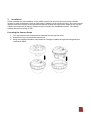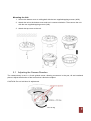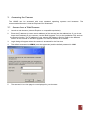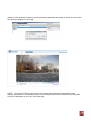
1
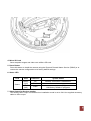
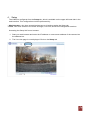
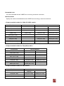
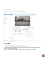
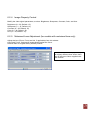
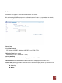
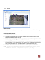
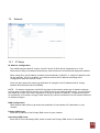
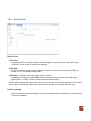
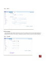
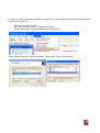
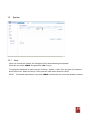
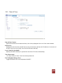
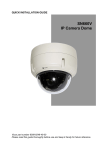
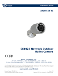
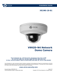
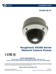
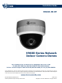
Installation Guide
XX224-30-07
V960D Series Network
Indoor Camera Domes
Vicon Industries Inc., 89 Arkay Drive, Hauppauge, New York 11788
Tel: 631-952-2288 Fax: 631-951-2288 Toll Free: 800-645-9116
24-Hour Technical Support: 800-34-VICON (800-348-4266) UK: 44/(0) 1489-566300
Vicon Industries Inc. does not warrant that the functions contained in this equipment will meet your requirements or that the
operation will be entirely error free or perform precisely as described in the documentation. This system has not been designed
to be used in life-critical situations and must not be used for this purpose.
www.vicon-security.com
Document Number: 8009-8224-30-07
Product specifications subject to change without notice.
Issued: 1112
Copyright © 2012 Vicon Industries Inc. All rights reserved.
Contents
1. Product Features ...........................................................................................4
2. Installation ....................................................................................................7
2.1 Adjusting the Camera Direction .....................................................................8
3. Accessing the Camera ....................................................................................9
3.1
3.2
3.3
3.4
3.5
3.6
Access from a Web Browser .........................................................................9
Accessing the Camera from the Internet....................................................... 11
Adjusting the Image and Focus ................................................................... 11
Live View .................................................................................................. 12
Video Stream Types ................................................................................... 12
How to Stream H.264 ................................................................................. 13
4. Setup ......................................................................................................... 14
5. Installation .................................................................................................. 15
5.1 Installation Mode ....................................................................................... 15
6. Video ........................................................................................................... 15
6.1 Video Codec ............................................................................................... 16
6.2
Camera................................................................................................... 19
6.2.1 Exposure Control .................................................................................... 19
6.2.2 Day & Night Control ................................................................................ 20
6.2.3 White Balance Control ............................................................................. 20
6.2.4 Image Property Control............................................................................ 21
6.2.5 Motorized Lens Adjustment (for models with motorized lens only) ................ 21
7. Audio ......................................................................................................... 22
8. Live ........................................................................................................... 23
9. SD Card ..................................................................................................... 24
9.1 Configuration ............................................................................................ 24
9.2 Event ....................................................................................................... 25
9.3 Periodical ................................................................................................. 26
10. FTP.......................................................................................................... 27
10.1 Configuration .......................................................................................... 27
10.2 Event...................................................................................................... 27
10.3 Periodical ............................................................................................... 28
11. Event ....................................................................................................... 29
11.1 Alarm Port ............................................................................................... 29
11.2 Motion .................................................................................................... 30
11.3 Mapping ................................................................................................. 31
12. Network .................................................................................................... 32
12.1
12.2
12.3
12.4
12.5
12.6
13.1
12.2
13.3
13.4
IP Setup ................................................................................................. 32
Service Port ............................................................................................ 34
RTP ........................................................................................................ 35
E-mail .................................................................................................... 35
DDNS ..................................................................................................... 36
UPnP...................................................................................................... 37
User ....................................................................................................... 39
Date & Time ............................................................................................ 40
Maintenance ........................................................................................... 41
Information ............................................................................................. 43
Vicon Standard Equipment Warranty ..................................................................... 46
1.
Product Features
The V960D Series HD/Megapixel IP camera dome is a high performance H.264 network camera,
designed for demanding security installations. It delivers crisp, clear images, disclosing every detail,
thanks to its top quality progressive-scan CMOS sensor and advanced image processing. V960D
series features a mechanical IR cut filter, which enables color video in high and low light conditions,
as well as IR sensitivity in ‘night’ mode. The V960D is available in a variety of models reflecting a
choice of resolutions and lens type. Refer to the table below. The term V960D refers to all cameras
in the series unless specifically stated otherwise. Refer to Vicon website product page for network
cameras, www.vicon-security.com/products-network-cameras.htm, to find the latest manual.
Model Number
Description
V960D-N312
V960D-N312M
SD (720x576, 0.3 megapixel) resolution camera with a 3.3-12 mm varifocal lens
SD (720x576, 0.3 megapixel) resolution camera with a 3.3-12 mm motorized
varifocal lens
SD (720x576, 0.3 megapixel) resolution camera with a 9-22 mm motorized varifocal
lens
720P (1280x1024, 1.3 megapixel) resolution camera with a 3.3-12 mm varifocal lens
720P (1280x1024, 1.3 megapixel) resolution camera with a 3.3-12 mm motorized
varifocal lens
720P (1280x1024, 1.3 megapixel) resolution camera with a 9-22 mm motorized
varifocal lens
1080P (1920x1080, 2 megapixel) resolution camera with a 3.3-12 mm varifocal lens
1080P (1920x1080, 2 megapixel) resolution camera with a 3.3-12 mm motorized
varifocal lens
1080P (1920x1080, 2 megapixel) resolution camera with a 9-22 mm motorized
varifocal lens
V960D-N922M
V961D-N312
V961D-N312M
V961D-N922M
V962D-N312
V962D-N312M
V962D-N922M
The optimal Power over Ethernet (IEEE 802.3af) supports power to the camera to be delivered via
the network, eliminating the need for a power outlet and reducing installation costs. Reliable AC
power could be guaranteed by using an Uninterruptible Power Supply (UPS).
Some of the camera domes in this series include a motorized lens, either 3.3-12 mm or 9-22 mm.
These lenses can be remotely configured and controlled conveniently through the web browser
interface.
The V960D offers a comprehensive set of network security and management features. This includes
support for port based network control (IEEE802.1X), which allows the camera to be connected to a
network secured with this control and HTTPS encryption, which provides a secure channel between
camera and application. It also enables authentication of the video source.
1. Network Connector
The V960D connects to the network via a standard network cable and automatically detects the speed
of the local network segment (10BaseT/100BaseTX Ethernet). This socket could also be used to
power the V960D via Power over Ethernet (PoE). The camera auto-senses the correct power level
when using a PoE switch, router or injector.
2. Power Connector
12 VDC or 24 VAC screw terminal power connector.
3. I/O Terminal Block for Audio and Alarm
3.1 Audio In
Audio in (line level), for line-in mono signal (only left channel is used from a stereo signal)
3.2 Audio out
The Audio output (line level), which could be connected to a line output of a microphone system
or an active speaker with a built-in amplifier.
3.3. Alarm In
One analog (dry contact) alarm input.
3.4 Alarm Out
One relay output (2A: 120 VAC/60 VDC).
4. Micro SD Card
Save snapshot images and video onto a Micro SD card.
5. Reset Button
Press this button to install the camera using the Dynamic Domain Name Service (DDNS) or to
restore the camera configuration to its factory default settings.
6. Status LED
LED
Status
Color
Indication
System Status
Green
(right)
On
Network connection is established.
Flash
Camera is booting up.
Firmware Upload in progress.
HW factory default in progress
Red
(left)
Flash
7. Video Output for Service monitor
This analog video output is available when installation mode is set to ON. Use supplied accessory
cable to video output.
2. Installation
Select a location for the installation of the V960D camera. Be sure the area around the selected
location is clear of obstacles (such as steel beams, headers, pipes, electrical wiring, etc.) which would
interfere with the mounting of the camera and that the location can support the weight of the unit [the
V960D unit weighs 0.9 lb (400 g)]. Cables must be routed to the installation location. The V960D
mounts directly to a ceiling or wall.
Preparing the Camera Dome
1. Turn the bottom cover clockwise and separate the unit and the cover.
2. Separate the top cover and the camera unit.
3. Using the supplied template, make holes for routing the cables through the ceiling/wall and
mark screw holes.
Mounting the Unit
1. Secure the bottom cover to ceiling/wall with the two supplied tapping screws (4x30).
2. Attach the unit to the bottom cover and turn it counter-clockwise. Then secure the unit
with the two supplied tapping screws (3x8).
3. Attach the top cover to the unit.
2.1
Adjusting the Camera Direction
The camera body is set in a 3-axis gimbal mount, allowing movement in the pan, tilt and rotational
planes. Adjust the direction of the lens so that it faces the subject.
CAUTION: Do not hold lens for adjustment.
3.
Accessing the Camera
The V960D can be accessed with most standard operating systems and browsers. The
recommended browser is Internet Explorer® for Windows®.
3.1 Access from a Web Browser
1.
2.
Launch a web browser (Internet Explorer or compatible equivalent).
Enter the IP address (or name server address) of the camera into the address bar. If you do not
know the IP address of your camera, use the Multi Upgrade Tool (on the Installation CD) and use
the Search function. The IP address of your camera will display in the list. Refer to the Network
section of this manual or the Multi Upgrade Tool manual XX224-30 for details.
3.
Login dialog will appear when the camera is accessed for the first time.
4.
The default username is ADMIN (must be uppercase) and the default password is 1234.
5.
The camera’s Live view page is now displayed in your browser.
When you first access the camera you will be asked to download and install an Active X control from
the camera to display a Live image.
NOTE: The layout of the live view page in the camera may have been customized to meet
specific requirements. Consequently, some of the examples and functions featured here may differ
from those displayed on your own Live View page.
3.2 Accessing the Camera from the Internet
Once installed, the camera will be accessible on the Local Area Network (LAN). Then you must
configure the router/firewall to allow incoming data traffic to access the camera from the Internet. For
security reasons this is usually done on a specific port, using port forwarding. Please refer to the
documentation for router/firewall for further instructions on port forwarding.
3.3 Adjusting the Image and Focus
To adjust the position of the lens:
Fixed Lens
1. Open the Live view page in your web browser.
- Select the Setup tab and open the Installation page.
- Set ‘Installation Mode’ to ‘ON’ and select the ‘Video Format'.
2. Connect supplied video monitor cable to video output connector, then connect it to analog
monitor with coaxial cable.
- Unscrew the zoom puller on the lens by turning it counter-clockwise.
- Adjust the zoom setting and re-tighten the zoom puller.
- Unscrew the focus puller on the lens to adjust the focus and re-tighten the focus puller.
3. Check the image from the Live view page on your web browser.
- Set ‘Installation Mode’ to ‘OFF’ to resume normal camera operation.
NOTE: DC Auto-Iris should always be disabled while focusing the camera. This will set the iris to the
wide open position, which yields the smallest depth of field, and thus the best conditions for focusing
the lens. When the focus has been set by using this method, it will maintain its focus in any kind of
lighting conditions.
Motorized Lens
1. Open the Live view page in your web browser.
- Select the Setup tab and open the Video -> Camera page.
- Click ‘Lens Adjustment’.
2. Set the desired Zoom and Focus (and Iris if applicable) positions.
3. Click ‘One Push Focus’ button to adjust focus automatically or set focus manually.
Note that the screen displayed may
be slightly different than shown here
due to the type of lens supplied with
the camera.
NOTE: DC Auto-Iris should always be disabled while focusing the camera. This will set the iris to
the wide open position, which yields the smallest depth of field, and thus the best conditions for
focusing the lens. When the focus has been set by using this method, it will maintain its focus in
any kind of lighting conditions.
3.4 Live View
Client PC Speaker (enable/disable)
Client PC Microphone (enable/disable)
Digital Zoom
Snapshot
Full Screen
Video Stream Change (1st Stream <> 2nd Stream)
Play: Start Video Stream
Stop: Stop Streaming
NOTE: It is possible that not all the buttons described below will be visible unless the Live View page
has been customized to display them.
3.5 Video Stream Types
Motion JPEG
This format uses standard JPEG images in the video stream. These images are then displayed and
updated at a rate sufficient to create a stream that shows constantly updated motion.
The Motion JPEG stream uses a considerable amount of bandwidth, but it also provides excellent
image quality and access to every individual image contained in the stream.
H.264 Protocols & Communication Methods
- RTP (Real-time Transport Protocol) is a protocol that allows programs to manage the real-time
transmission of multimedia data, via Unicast or Multicast.
- RTSP (Real-Time Streaming Protocol) serves as a control protocol to negotiate the type of transport
protocol used for the stream. RTSP is used by a viewing client to start a Unicast session
- UDP (User Datagram Protocol) is a communications protocol that offers limited service for
exchanging data in a network that uses the Internet Protocol (IP). UDP is an alternative to the
Transmission Control Protocol (TCP). The advantage of UDP is that it is not required to deliver all
data and may drop network packets when there is network congestion. This is suitable for live
video, as there is no point in re-transmitting old information that will not be displayed anyway.
H.264 Protocols & Communication Methods (continued)
Unicasting is communication between a single sender and a single receiver over a network. This
means that the video stream is transmitted independently to each user, and each user receives its
own video stream. A benefit of unicasting is in case one stream fails, it only affects one user.
Multicasting is bandwidth-conserving technology that reduces bandwidth usage by simultaneously
delivering a single stream of information to multiple network recipients. This technology is used
primarily on delimited networks (intranets), as each user needs an uninterrupted data flow and should
not rely on network routers.
3.6 How to Stream H.264
Deciding on the combination of protocols and methods to use depends on your viewing
requirements and on the properties of your network.
RTP+RTSP: This method (actually RTP over UDP and RTSP over TCP) should be your first
consideration for live video, especially when it is important to always have an up-to-date video
stream, even if some images are lost due to network problems. This could be configured as
Multicast or Unicast.
Multicasting provides the most efficient usage of bandwidth, especially when there are large
numbers of clients viewing simultaneously. Note however, that a multicast broadcast could not pass
a network router unless the router is configured to allow this. For example, it is not possible to
multicast over the Internet.
Unicasting should be used for video-on-demand broadcasting, so that there is no video traffic on
the network until a client connects and requests the stream. However, as more and more unicast
clients get connected, the traffic on the network will increase and may cause congestion. Although
there is a maximum of 10 unicast viewers, note that all multicast users combined count as 1
unicast viewer.
RTP/RTSP: This unicast method is RTP tunneled over RTSP. This could be used to exploit the fact
that it is relatively simple to configure firewalls to allow RTSP traffic.
RTP/RTSP/HTTP or RTP/RTSP/HTTPS: These two methods could also be used to traverse
firewalls. Firewalls are commonly configured to allow the HTTP protocol, allowing RTP to be
tunneled.
4.
Setup
The V960D is configured from the Setup tab, which is available on the upper-left hand side in the
web interface. This configuration could be performed by:
- Administrators, who have unrestricted access to all settings under the Setup tab.
- Users, who have access to the Video & Image, Live View, and Event Configuration sections.
Accessing the Setup link from a browser:
1. Start your web browser and enter the IP address or name server address of the camera into
the address bar.
2. The Live view page is now displayed. Click on the Setup tab.
5. Installation
The following descriptions show examples of some of the features available with V960D.
5.1 Installation Mode
Installation Mode allows use of the analog BNC output from the camera to connect the camera to a
service monitor, in order to adjust the positioning of the camera and focus the lens.
ON :
OFF :
Analog Output is enabled; both IP video streams are set to VGA (640 x 480) resolution.
Analog Output is disabled.
NOTE:
You must turn Installation Mode OFF to utilize the megapixel features of the camera.
Additionally, all installation setup must be done prior to the camera being used with a
VMS, including ViconNet; the VMS forces the Installation Mode to OFF.
6. Video
The following descriptions show examples of some of the features available with V960D.
6.1 Video Codec
This section allows you to choose the compression codec for each of the video streams.
Motion JPEG
This format uses standard JPEG still images in the video stream. These images are then displayed
and updated at a rate sufficient to create a stream that shows constantly updated motion.
The Motion JPEG stream uses a considerable amount of bandwidth, but also provides excellent
image quality and access to every individual image contained in the stream.
Multiple clients accessing Motion JPEG streams could use different image settings.
H.264
This is a video compression standard that makes good use of bandwidth and could provide
high-quality video streams at less than 1 Mbit/s.
The H.264 standard provides the scope for a large range of different coding tools for use by
various applications in different situations, and the V960D provides certain subsets of these tools.
Using H.264, it is also possible to control the bit rate, which in turn allows the amount of bandwidth
usage to be controlled. CBR (Constant Bit Rate) is used to achieve a specific bit rate by varying the
quality of the H.264 stream. While using VBR (Variable Bit Rate), the quality of the video stream is
kept as constant as possible, at the cost of a varying bit rate.
Size
Video output resolution. See below for camera resolution tables.
Frame Rate
2.5 ~ 30fps in normal mode (1 ~ 30fps in slow shutter mode)
NOTE: If the slow shutter mode is turned on and the low light condition is met, the image rate
automatically goes down. In this case, the image is half of the normal mode.
GOP Size
1 ~ 60 frames. Vicon recommends that GOP be set at the same value as the fps.
Bitrate Control (CBR or VBR)
When using H.264 compression, if there is only limited bandwidth available, a constant bit rate
(CBR) is recommended, although this may compromise image quality. Use a variable bit rate (VBR)
for the best possibly image quality.
Average Bitrate (512Kbps ~ 8Mbps)
Recommended bit rate for VGA (640x480): 800Kbps ~ 1Mbps
Recommended bit rate for 720p (1280x720): 3Mbps ~ 4Mbps
Recommended bit rate for 1080p (1920x1080): 6Mbps ~ 8Mbps
Boost Quality
The Boost feature is used in conjunction with Video Motion Detection (VMD). When this feature is
turned ON, the Boost FPS can be set to a different value than the Frame Rate set for the camera in
the field above. When motion is detected, the camera will boost the fps from the regular level set for
the camera to this boosted level for the duration of the motion. Boost Quality can be set ON or OFF.
Quality
1 ~ 100 frames; this parameter will only be available in MJPEG mode.
Anti-Flicker Mode
60Hz: NTSC
50Hz: PAL or “flicker-free” mode (to use the camera in locations lit by fluorescent lighting).
Video Mirroring
The image can be reversed to view it as a mirror image. Select from None, Horizontal, Vertical or flip
the image (horizontal and vertical).
Bandwidth Limit
Limit the bandwidth that the V960D can use during a network connection.
Max Bandwidth
Specify the maximum bandwidth that the V960D can use during a network connection.
< Output resolution table for 1080p (Full HD) model >
First Stream
Second Stream
1080p (1920 x 1080)
-
-
1.3MP (1280 x 1024)
-
-
720p (1280 x 720)
720p (1280 x 720)**
VGA (640 x 480)
-
720p Wide Mode
(1280 x 720)
720p (Wide Mode)**
(1280 x 720)
VGA (640 x 480)
QVGA (320 x 240)
XGA (1024 x 768)
-
-
4CIF (704 x 480/576)
4CIF (704 x 480/576)
CIF (352 x 240/288)
VGA (640 x 480)
VGA (640 x 480)
QVGA (320 x 240)
CIF (352 x 240/288)
CIF (352 x 240/288)
-
QVGA (320 x 240)
QVGA (320 x 240)
-
**Only available in MJPEG mode. Frame rate will be limited to 15 fps on both streams.
< Output resolution table for 720p (HD) model >
First Stream
Second Stream
1.3MP (1280 x 1024)
-
-
720p (1280 x 720)
-
-
720p Wide Mode (1280 x 720)
VGA (640 x 480)
QVGA (320 x 240)
XGA (1024 x 768)
-
-
4CIF (704 x 480/576)
4CIF (704 x 480/576)
CIF (352 x 240/288)
VGA (640 x 480)
VGA (640 x 480)
QVGA (320 x 240)
CIF (352 x 240/288)
CIF (352 x 240/288)
-
QVGA (320 x 240)
QVGA (320 x 240)
-
< Output resolution table for VGA model >
First Stream
Second Stream
4CIF (704 x 480/576)
4CIF (704 x
480/576)
CIF (352 x 240/288)
VGA (640 x 480)
VGA (640 x 480)
QVGA (320 x 240)
CIF (352 x 240/288)
CIF (352 x 240/288)
-
QVGA (320 x 240)
QVGA (320 x 240)
-
6.2
Camera
This section allows you to adjust various camera settings.
6.2.1 Exposure Control
Exposure Mode
AUTO: Use this setting for automatic exposure control.
MANUAL: Use this setting to control camera exposure manually.
To compensate for poor lighting conditions, you can adjust the Color level, Brightness, Sharpness,
Contrast, Exposure control, and Iris.
NOTE: When AE is enabled, some of the submenus (i.e., AGC Gain) will be disabled.
Slow Shutter Mode
For low light conditions, turn ON slow shutter mode.
Max AGC Gain
For low light conditions, select HIGH value; otherwise select LOW.
Iris Control
Auto: Iris adjusts automatically based on lighting condition.
Manual: Set iris position manually (through software adjustment only).
Best Quality: Set iris position to maximize resolution.
Depth of Field: Set iris position to maximize depth of field.
BLC Control (Back Light Compensation)
The BLC adjusts the exposure of scenes with strong backlight in the center-bottom of the image.
When the image background is too bright, or the subject too dark, backlight compensation makes
the subject appear clearer. The settings for low light behavior determine how the camera behaves at
low light levels. These settings affect video image quality and how much noise is in the images.
Select ON or OFF.
6.2.2 Day & Night Control
Day & Night Mode
AUTO / DAY / NIGHT
Set this filter to NIGHT to allow the camera to 'see' infrared light, removing the IR cut filter, when
using an IR illuminator. This will make the image clearer. If set to AUTO, the camera will
automatically switch between IR cut filter DAY and NIGHT, according to the current lighting
conditions.
6.2.3 White Balance Control
WB Mode
ON: ATW (Automatic White Balance)
OFF: MWB (Manual White Balance)
The White Balance adjustment setting is used to make the colors in the image appear consistent,
compensating for the different colors present in different light sources.
The V960D camera can be set to automatically identify the light source and compensate for its color
temperature. If necessary, the type of light source could be set manually.
6.2.4 Image Property Control
Modify the video signal parameters, such as: Brightness, Sharpness, Contrast, Color, and Hue.
Brightness (0 ~ 30; Default: 15)
Sharpness (1 ~ 15; Default: 12)
Contrast (0 ~ 30; Default: 15)
Color (0 ~ 30; Default: 15)
Hue (0 ~ 30; Default: 15)
6.2.5 Motorized Lens Adjustment (for models with motorized lens only)
Adjust the lens (Zoom, Focus and Iris, if applicable) from this window.
One Push Focus: Camera will automatically adjust the focus.
Default: Back to original factory default position.
Note that the screen displayed may
be slightly different than shown here
due to the type of lens supplied with
the camera.
7.
Audio
The V960D can transmit audio to other clients and can also play audio received from other clients.
This section describes the basic audio settings, such as setting the communication codec and
adjusting the sound levels for the microphone and speakers connected to the camera.
Enable Audio
Audio can be turned on or off by selecting ENABLE or DISABLE from the dropdown list.
Codec
Select G.711 u-law.
MIC/Speaker Volume
Select a volume for the microphone and speakers from 5-100 or Mute.
Audio Input
Audio from a connected line-in source can be connected to the Audio in connector on the V960D
camera. If there are problems with the sound input being too low or high, you can adjust the input
gain for the microphone connected to the V960D.
8.
Live
The V960D can support up to 10 simultaneous users via Unicast.
With multicasting, V960D can support an unlimited number of users. If supported on the network,
consider using the Multicast function, as the bandwidth consumption will be much lower.
Viewer Setup
Live View Protocol
RTP Unicast (UDP)/RTP Multicast (UDP)/RTP over RTSP (TCP).
Buffering Time (frame based)
Determines (0 ~ 90) x 1/30 sec (0 ~ 3 sec)
Viewer OSD Setup
Date: Determines whether the date is displayed; select ON or OFF.
Resolution: Determines whether the camera resolution is displayed; select ON or OFF.
Event State: Determines whether the event state is shown on display window (as shown in Live
view); select ON or OFF:
AI : Alarm In
AO: Alarm Out
M : Motion
9.
SD Card
9.1 Configuration
SD Card Configuration
This configuration page allows you to save video and still images to the Micro SD (SDHC) card.
NOTE: This function cannot be used when Installation mode is turned ON. Set the first stream to
1280x720 or 1280x720 (wide) in the Video > Codec section, and second stream to M-JPEG or
‘None’.
Overwriting
The system will overwrite the oldest data on the SD card to continually record the newest data.
Enable or Disable.
SD Status
Shows present SD card status. It also shows whether the SD card is present and the capacity left on
it in kilobytes (KB).
SD Safety Remove
Mount/Unmount buttons: The Mount button notifies the system after the SD card is inserted. The
Unmount button is to notify the system before the SD card is removed. This is a similar function to
the ‘remove the hardware safely before taking out the USB’ in the Windows OS.
Erase Image Files
Insert the SD card and press ERASE to delete files from the card.
NOTE: The user can download the images from the SD card using the FTP function. Turn FTP
server on and connect to the camera. See Chapter 9.1 for details.
9.2 Event
Event SD Writing
You can configure the camera to store still images based on events such as Alarm In and Motion
detection.
NOTE: This function cannot be used when Installation mode is turned ON. Set the first stream to
1280x720 or 1280x720 (wide) in the Video > Codec section, and second stream to M-JPEG or
‘None’.
SD Writing
SD Writing will Enable/Disable event recording to the SD card.
When Disabled, all remaining menus will be deactivated.
Directory
The name of the sub-directory where the still images will be stored when an Event occurs.
File Prefix
You may add a file name prefix to the stored image file name.
Example: If the file prefix is ‘alm’, the still image would be saved as alm_date_time.jpg.
SD Write Mapping
Choose which types of events (Alarm In or Motion) will be recorded to the SD card by checking the
desired event.
Effective Period
Decide whether to save all the events that are happening at all hours of the day (Always), or only the
events that occur during specific times of the day. The Schedule method is used to save events on
the SD card during a specific time range. The start time and the end time can be set using the
dropdown list.
9.3 Periodical
Periodical SD Writing
This is the setting page to save the still shot in the Micro SD card periodically.
NOTE: This function cannot be used when Installation mode is turned ON. Set the first stream to
1280x720 or 1280x720 (wide) in the Video > Codec section, and second stream to M-JPEG or
‘None’.
The Directory and File Prefix fields are same as on the SD Card > Event page.
Interval allows for saving still images based on frequency (1 image every 10 sec, for example).
Use the drop-down control to set from 10 seconds to 1 hour.
Effective Period is configured the same as on the SD card > Event page.
Periodically, it saves the still image during a specific time range only.
10.
FTP
10.1 Configuration
Server Configuration
Enable/Disable the FTP function to download saved content from the SD Card remotely.
When it is Enabled, the FTP client can download the saved content without removing the SD Card.
Client Configuration
Allows transmission of still images to remote sites, using the FTP server. Set the information for FTP
transmission by inserting the IP address, Username and Password of the remote FTP Server.
NOTE: This function cannot be used when Installation mode is turned ON. Set the first stream to
1280x720 or 1280x720 (wide) in the Video > Codec section, and second stream to M-JPEG or
‘None’.
10.2 Event
Event FTP Sending
Allows transmission of still images to the FTP server at remote sites when an event occurs.
NOTE: This function cannot be used when Installation mode is turned ON. Set the first stream to
1280x720 or 1280x720 (wide) in the Video > Codec section, and second stream to M-JPEG or
‘None’.
The menu structure is similar to the SD Card >Event menu, but instead of saving the still image to
the SD card on an event, it transmits to the FTP server configured in the FTP > Config menu.
10.3 Periodical
Periodical FTP Sending
Allows transmission of still images periodically to the FTP server of remote sites.
NOTE: This function cannot be used when Installation mode is turned ON. Set the first stream to
1280x720 or 1280x720 (wide) in the Video > Codec section, and second stream to M-JPEG or
‘None’.
The menu configuration is similar to the SD Card >Periodical menu, but instead of saving the still
images to the SD card on an event, it transmits to the server configured in the FTP > Config menu.
11.
Event
11.1 Alarm Port
Alarm Input (dry contact)
Used for connecting external alarm contacts and triggering specific alarm-based events. The input is
typically connected to a motion detector or any other external security device, so that recording can
be triggered and/or still images could be recorded and/or uploaded whenever the sensor is activated.
Enable or Disable the alarm input and define it as Normally Open (N/O) or Normally Closed (N/C).
Name the alarm in the Text field.
Alarm Output (relay output)
This could drive a maximum load of 60 VDC or 120 VAC at 2 A directly. If the output is used with an
external relay, a diode must be connected in parallel with the load for protection against any voltage
transients. Enable or Disable the alarm output and select a mode of SYNC or LATCHED.
Duration
This parameter sets the minimum period before the alarm resets. Another alarm will not be triggered
until this period has lapsed, even if the tampering conditions are otherwise met. This could help to
prevent false alarms for known conditions that affect the image.
Caution! Connecting AC to the inputs will damage the unit!
11.2 Motion
Motion Detection
Motion detection is used to generate an alarm whenever movement occurs within the video image.
A total of 4 motion detection zones can be configured.
Configuring Motion Detection
1.
Click Motion in the Event menu.
2.
Click Area1-4 button for the area to be defined and select the corresponding area for motion
detection by clicking the relevant color box.
3.
Click the box on the video image where the motion area is to be located and adjust the size of the
area by dragging the outlined box across and down in one motion.
4.
Adjust the Object Sensitivity from the drop down list, 1-10. The Sensitivity list only displays when
an area is selected; it is not visible when All View is selected. Use the Selectall button to have the
entire scene in the selected area. Deleteall is available to eliminate all selected areas.
5.
Click Save. When motion occurs in the defined area, a red dot appears on the Live video.
NOTE: Using the motion detection feature will consume more of the cameras resources, and this
could decrease the camera’s overall performance, depending on your settings.
11.3 Mapping
Event Mapping
It is possible to define conditions that would cause the camera to respond with certain actions.
A triggered event happens as a result of an event which is mapped within this menu.
This could be caused by motion detection or an external alarm input.
Alarm Out events could be triggered by either Motion or Alarm In.
E-mail notification could be sent by either Motion or Alarm In.
12.
Network
12.1 IP Setup
IP Address Configuration
The V960D supports both IP version 4 and IP version 6 (IPv6 will be supported as of v3.0).
Both versions may be enabled simultaneously, and at least one version should always be enabled.
When using IPv4, the IP address could be set automatically via DHCP, or a static IP address could
be set manually. If IPv6 is enabled, your camera receives an IP address according to the
configuration within the network router.
There are also options for setting up notification of changes in the IP address and for using a
Dynamic Domain Name Service (DDNS).
NOTE: IP address assignment via DHCP may lead to the situation where the IP address changes
and you lose contact with the camera. If your DHCP server can update a DNS server, you can access
the V960D by a static host name, regardless of having a dynamic IP address. Configure the options
for notification of IP address change (under Services) to receive notification from the camera when the
IP address changes.
DNS Configuration
DNS (Domain Name Server) provides the translation of host names to IP addresses on your
network.
Primary DNS server
Enter the IP address of the Primary DNS server for your network.
Secondary DNS server
Enter the IP of the Secondary DNS, which is used if the Primary DNS server is unavailable.
How to Assign an IP Address
Default setting is set to “DHCP” and “UPnP” function is set to ON. If your network has a DHCP server
and the UPnP function is enabled on your PC, you can find the camera in “My Network”. Refer to the
Multi Upgrade Tool manual for detailed instructions.
Execute the Multi Upgrade Tool (from the Installation CD); it will search cameras on the network
automatically.
1) After the list of detected devices appears, select the camera you are trying to configure.
2) Select the Network type as Static or DHCP. If Static is selected, enter all of the network
information for your camera.
3) Select the “Change IP Address” button. The message “Do you want to change IP address?” will
display; select “Yes” from the pop-up window.
4) Check the Type as Static or DHCP from the list.
When you double-click the camera within the list, the default web browser (Internet Explorer or
compatible equivalent) will open and automatically connect to the camera.
12.2 Service Port
Service Port
HTTP Port
The default HTTP port number (80) could be changed to any port within the valid port range
(1-65535). This is useful for simple port mapping.
RTSP Port
The RTSP protocol allows a connecting client to start an H.264 stream. Enter the RTSP port
number to use. The default setting is 554.
HTTPS Port (HTTPS will be supported in future versions)
The default HTTPS port number (443) could be changed to any port within the valid range
(1024-65535). HTTPS is used to provide encrypted web browsing.
NOTE: After changing the default port numbers, the user can use the Multi Upgrade Tool’ to search
and connect automatically if they can’t remember the specific port numbers that they used.
Port Forwarding
Select the method of port forwarding. It can also be deleted. Enter the External IP of the device it
is being forwarded to.
12.3 RTP
RTP Port Range
The IP address, port numbers, and Time-To-Live (TTL) value are for use for the video stream(s) in
Multicast H.264 format. Only certain IP addresses and port numbers should be used for Multicast.
12.4 E-mail
You must turn Notification to ‘ON’ and then enter the host names or addresses for your mail servers in
the fields provided to enable the sending of event and error email messages from the camera to
predefined addresses via SMTP.
Notes:
Frequency: Mail server may register the sender to SPAM list when frequency is set to “1 Min”.
To be safe, set to “5 Min”.
From: Specify the name who sent e-mail notification. It is recommended to use e-mail format
like [email protected]. Some e-mail server will refuse it.
12.5 DDNS
The Dynamic Domain Name Service (DDNS) can provide your camera with its own name server
address (URL), which can then be used to access it over the Internet. The product can be
unregistered from the service at any time. To do this click Network > DDNS and turn the DDNS Off.
How to setup the DDNS:
1) DDNS set to ON.
“mac address.dvrlink.net” is registered to the DDNS server.
User can connect to the camera with:
“http://mac address.dvrlink.net”.
2) DDNS set to ON and user inputs “user-defined name”.
“mac address.dvrlink.net” and “user-defined name.dvrlink.net” are both registered together.
User can connect to the camera using either:
“http://mac address.dvrlink.net” or “http://user-defined name.dvrlink.net”.
If “user-defined name” is already registered, an error message is shown; try a different name.
12.6 UPnP
Universal Plug & Play (UPnP) allows you to find the IP camera automatically on your network.
In order to be able to detect the camera automatically, you must enable the UPnP function on both the
camera and on your PC.
Camera : Set UPnP to “ON”
PC : Open “Control Panel” >”Network Connection”
Select “Advanced” >”Optional Networking Components…”
Select “Network Services” and click “Details”. Then select “UPnP user Interface”
13.
System
13.1 User
When you access the camera, the Configure Root Password dialog box appears.
Enter the user name ADMIN and password 1234 to log in.
To change the password or add a user, go to Setup > System > User. Fill in the User ID, Password
and E-mail server. Select the Group. Then press the ‘Add’ button and click ‘SAVE’.
NOTE:
The default administrator username ADMIN is permanent and cannot be deleted or altered.
12.2 Date & Time
Date & Time Format
Specify the formats for the date and time (12h or 24h) displayed in the Live View video streams.
NTP Server
Synchronize the time from an NTP server every 60 minutes. Specify the IP address or host name of
the NTP server you are using. This can also be done manually.
Local Time/PC Sync/SAVE
Specify local time manually or synchronize the time to PC time automatically.
Time Zone Setup
You may select your time zone from the drop-down list.
D.S.T (Daylight Saving Time)
Toggle automatic DST clock adjustment ON/OFF.
13.3 Maintenance
System Name
Choose a system name to identify the camera when using e-mail notifications.
System Reboot
Reboots the camera.
Factory Default
Resets the camera back to the original factory default settings.
Save System and User Data
System settings can be saved to a PC.
Load Data
The system settings can be reloaded in case of accidental factory reset or can be transferred to
another camera if multiple units need to be installed with the same settings.
Firmware Update
From time to time, firmware will be released to update the camera, which will contain feature
additions and other improvements. Always read the upgrade instructions and release notes that
accompany each new firmware release before updating the firmware.
NOTE:
Preconfigured and customized settings should be saved before the firmware is upgraded.
Firmware Update Procedure
1. Save the firmware file to your computer.
2. Go to Setup > System > Maintenance within the camera web browser setup.
3. In the Firmware Update section, browse to the desired firmware file on your computer. Click OK.
NOTE: Do not disconnect power to the unit during the upgrade. The unit will restart automatically
after the upgrade has completed. (1~5 minutes).
4. If you suspect the firmware upgrade for the camera has failed, always wait at least 5-10 minutes
before restarting the upgrade process.
5. Vicon reserves the right to charge for any camera repair which can be attributed to faulty
upgrading by the user. Always read the upgrade instructions and firmware release notes before
updating the firmware.
System Reset (Factory Default Reset)
There are two ways to reset the camera back to factory default.
Using the web browser:
1. Go to SETUP > System > Maintenance.
2.
Click Factory Default Button and wait 1 minute for camera to reboot.
Using the Reset Button on the camera:
1.
2.
After the camera is powered up, i.e., LED is steady green, press and hold the Reset button until
the Status Indicator color changes to RED and starts blinking rapidly (this may take up to
15 seconds).
Release the Reset button.
3. When the Status Indicator changes to Green (which may take up to 1 minute), the process is
complete and the camera has been reset.
NOTE:
The unit will now have the default IP address from a DHCP server.
Use the Multi Upgrade Tool’ to discover and connect to the camera.
13.4 Information
System Information
After updating firmware, you can confirm the new F/W version here.
Vicon Standard Equipment Warranty
Vicon Industries Inc. (the “Company”) warrants your equipment to be free from defects in material and
workmanship under Normal Use from the date of original retail purchase for a period of three years, with the
following exceptions:
1. VCRs, all models: Labor and video heads warranted for 120 days from date of original retail purchase.
All other parts warranted for one year from date of original retail purchase.
2. LCD and CRT monitors, all models: One year from date of original retail purchase.
3. Uninterruptible Power Supplies: Two years from date of original retail purchase.
4. VDR-700 Recorder Series: One year from date of original retail purchase.
5. V5616MUX: One year from date of original retail purchase.
6. Arecont Cameras: One year from date of original retail purchase.
7. FMC series fiber-optic media converters and associated accessories: Lifetime warranty.
8. For PTZ cameras, “Normal Use” excludes prolonged use of lens and pan-and-tilt motors, gear heads, and gears due to
continuous use of “autopan” or “tour” modes of operation. Such continuous operation is outside the scope of this warranty.
9. Vicon Security Management Systems (SMS) All Models: All hardware is warranted for two years from date of original retail
purchase.
10. Any product sold as “special” or not listed in Vicon’s commercial price list: One year from date of original retail purchase.
Date of retail purchase is the date original end-user takes possession of the equipment, or, at the sole
discretion of the Company, the date the equipment first becomes operational by the original end-user.
The sole remedy under this Warranty is that defective equipment be repaired or (at the Company’s option)
replaced, at Company repair centers, provided the equipment has been authorized for return by the Company,
and the return shipment is prepaid in accordance with policy.
The Company will not be obligated to repair or replace equipment showing abuse or damage, or to parts which
in the judgment of the Company are not defective, or any equipment which may have been tampered with,
altered, misused, or been subject to unauthorized repair.
Software supplied either separately or in hardware is furnished on an “As Is” basis. Vicon does not
warrant that such software shall be error (bug) free. Software support via telephone, if provided at no
cost, may be discontinued at any time without notice at Vicon’s sole discretion. Vicon reserves the
right to make changes to its software in any of its products at any time and without notice.
This Warranty is in lieu of all other conditions and warranties express or implied as to the Goods,
including any warranty of merchantability or fitness and the remedy specified in this Warranty is in lieu
of all other remedies available to the Purchaser.
No one is authorized to assume any liability on behalf of the Company, or impose any obligations on it in
connection with the sale of any Goods, other than that which is specified above. In no event will the Company
be liable for indirect, special, incidental, consequential, or other damages, whether arising from interrupted
equipment operation, loss of data, replacement of equipment or software, costs or repairs undertaken by the
Purchaser, or other causes.
This warranty applies to all sales made by the Company or its dealers and shall be governed by the laws of
New York State without regard to its conflict of laws principles. This Warranty shall be enforceable against the
Company only in the courts located in the State of New York.
The form of this Warranty is effective March 1, 2011.
THE TERMS OF THIS WARRANTY APPLY ONLY TO SALES MADE WHILE THIS WARRANTY IS IN
EFFECT. THIS WARRANTY SHALL BE OF NO EFFECT IF AT THE TIME OF SALE A DIFFERENT
WARRANTY IS POSTED ON THE COMPANY’S WEBSITE, WWW.VICON-SECURITY.COM. IN THAT
EVENT, THE TERMS OF THE POSTED WARRANTY SHALL APPLY EXCLUSIVELY.
Vicon Part Number: 8006-9010-03-09
Rev 0311
Vicon Industries Inc.
Corporate Headquarters
89 Arkay Drive
Hauppauge, New York 11788
631-952-2288 800-645-9116
Fax: 631-951-2288
Vicon Europe
Headquarters
Brunel Way
Fareham, PO15 5TX
United Kingdom
+44 (0) 1489 566300
Fax: +44 (0) 1489 566322
Vicon Germany
Kornstieg 3
D-24537 Neumuenster
Phone: +49 (0) 4321 8790
Fax: +49 (0) 4321 879 97
Far East Office
Unit 5, 17/F, Metropole Square
2 On Yiu Street, Shatin
New Territories,
Hong Kong
(852) 2145-7118
Fax: (852) 2145-7117
Internet Address: www.vicon-security.com