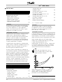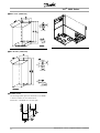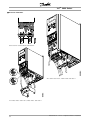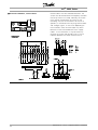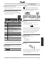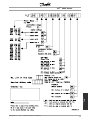
1
VLT® 2800 Series
■
Contents
Quick Setup
.......................................................................................................
General warning .....................................................................................................
Mechanical Installation ...........................................................................................
Electrical Installation, power ...................................................................................
Electrical Installation, control cables .......................................................................
Programming .........................................................................................................
Motor start .............................................................................................................
Safety regulations ..................................................................................................
Warning against unintended start ...........................................................................
3
3
3
3
3
3
4
4
4
Introduction to VLT 2800
............................................................................. 5
Software version .................................................................................................... 5
High voltage warning ............................................................................................. 7
These rules concern your safety ............................................................................. 7
Warning against unintended start ........................................................................... 7
Control unit ............................................................................................................ 8
Manual initialisation ................................................................................................. 8
Hand Auto ............................................................................................................. 9
Automatic motor tuning ......................................................................................... 10
Programming
11
11
18
28
35
45
Installation
53
53
57
58
59
60
62
62
62
62
63
63
63
64
64
64
64
65
65
65
65
66
67
....................................................................................................
Operation & Display ...............................................................................................
Load and Motor .....................................................................................................
References & Limits ...............................................................................................
Inputs and outputs .................................................................................................
Special functions ....................................................................................................
.........................................................................................................
Mechanical dimensions ..........................................................................................
Mechanical installation ...........................................................................................
General information about electrical installation ......................................................
EMC-correct electrical installation ..........................................................................
Electrical installation ...............................................................................................
Safety clamp ..........................................................................................................
Pre-fuses ................................................................................................................
Mains connection ...................................................................................................
Motor connection ...................................................................................................
RFI switch ..............................................................................................................
Direction of motor rotation .....................................................................................
Parallel connection of motors .................................................................................
Motor cables ..........................................................................................................
Motor thermal protection .......................................................................................
Brake connection ...................................................................................................
Earth connection ....................................................................................................
Load sharing ..........................................................................................................
Tightening Torque, Power Terminals ......................................................................
Control of mechanical brake ..................................................................................
Access to control terminals ....................................................................................
Electrical installation, control cables .......................................................................
Tightening torques, control cables ..........................................................................
MG.28.A9.02 - VLT is a registered Danfoss trademark
1
VLT® 2800 Series
Electrical installation, control terminals ...................................................................
Relay connection ...................................................................................................
VLT Software Dialog ..............................................................................................
Connection examples ............................................................................................
All about VLT 2800
.........................................................................................
Order form .............................................................................................................
Display readout ......................................................................................................
Warnings/alarm messages .....................................................................................
Warning words, extended status words and Alarmwords .....................................
Special conditions ..................................................................................................
Aggressive environments ........................................................................................
Derating for high switching frequency - VLT 2800 ..................................................
Temperature-dependent switch frequency .............................................................
Galvanic Isolation (PELV) ........................................................................................
EMC emission ........................................................................................................
UL Standard ..........................................................................................................
General technical data ...........................................................................................
Technical data, mains supply 1 x 220 - 240 V/3 x 200-240V ................................
Technical data, mains supply 3 x 380 - 480 V .......................................................
Available literature ...................................................................................................
Supplied with the unit .............................................................................................
Index
2
67
67
67
68
69
69
70
70
74
75
75
75
75
76
76
78
79
83
84
85
85
...................................................................................................................... 93
MG.28.A9.02 - VLT is a registered Danfoss trademark
VLT® 2800 Series
■ Quick
Setup
■ General warning
Using this Quick Setup, you can carry out quick and
EMC-correct installation of the frequency converter
in five steps. The Operating Instructions, which are
also enclosed, give other examples of installation
and describe all functions in detail.
■ Electrical Installation, control cables
Remove the front cover underneath the control panel.
Place a jumper between terminals 12 and 27.
■ Mechanical Installation
VLT 2800 frequency converters allow side-by-side
installation. Because of the need for cooling, there
must be 10 cm free air passage above and below
the frequency converter. Drill holes in accordance
with the measurements given in section Mechanical
dimensions. Retighten all four screws.
Fit the decoupling plate to the power cables and
the earth screw (terminal 95).
Quick
Setup
Read the safety instructions on the next
page before installing the unit.
■ Programming
Carry out programming on the control panel. Press
the [QUICK MENU] key to enter the Quick menu. In
this menu, parameters can be selected by means of
the [+] and [-] keys. The parameter values can be
changed by pressing [CHANGE DATA]. Changes are
programmed using the [+] and [-] keys. Finish the
change of a parameter setting by pressing [CHANGE
DATA]. A change of parameter values is saved
automatically after a mains failure. If the display shows
three dots at the right, the parameter value has more
than three digits. In order to see the value, activate
[CHANGE DATA]. Press [QUICK MENU]: Set the motor
parameters that are on the nameplate of the motor:
Motor
Motor
Motor
Motor
Rated
power [kW]
voltage [V]
frequency [Hz]
current [A]
motor speed
parameter
parameter
parameter
parameter
parameter
102
103
104
105
106
Activate AMT:
Automatic motor tuning
parameter 107
Set reference range
■ Electrical Installation, power
Please note that the power terminals can be removed.
Connect mains to the mains terminals of the frequency
converter, i.e. 91, 92, 93 and the earth connection to
terminal 95. Fit a screened/armoured cable from the
motor to the motor terminals of the frequency converter,
i.e. U, V, W. The screen ends in a screen connector.
MG.28.A9.02 - VLT is a registered Danfoss trademark
Min. reference, RefMIN
Max. reference, Ref MAX
Ramp-up time [s]
Ramp-down time [s]
parameter 204
parameter 205
parameter 207
parameter 208
In parameter 002 Local/remote control, the frequency
converter mode can be selected as Remote
3
VLT® 2800 Series
operation [0], i.e. via the control terminals, or
Local [1], i.e. via the control unit.
Set the control location to Local [1].
Local/remote operation = Local [1] Par. 002
Set the motor speed by adjusting the
Local reference
Local reference Parameter 003
■ Safety regulations
The voltage of the frequency converter
can be fatal whenever it is connected to
mains. Incorrect installation of the motor
or the frequency converter may lead to damage to
the equipment, serious personal injury or death.
Consequently, the provisions of this Quick Setup,
as well as national and local rules and safety
regulations, must be complied with.
Touching the electrical parts may be fatal, even
after the equipment has been disconnected from
mains: wait at least 4 min.
1. The mains supply to the frequency converter must
be disconnected if repair work is to be carried out.
2. The [STOP/RESET] key on the control panel of the
frequency converter does not disconnect the mains
supply and is thus not to be used as a safety switch.
3. Correct protective earthing of the unit must be
established, the user must be protected against
supply voltage, and the motor must be protected
against overload in accordance with applicable
national and local regulations.
4. The earth leakage current is higher than 3.5 mA.
5. Protection against motor overload is not included
in the factory setting. If this function is required,
set parameter 128 Motor thermal protection to
data value ETR Trip or ETR Warning.
6. Check that the mains supply has been disconnected
before removing the motor and mains plugs.
4
■ Motor start
Press [Start] to start the motor. Set the motor speed
by adjusting parameter 003 Local reference.
Check whether the direction of rotation of the motor
shaft is clockwise. If not, exchange any two phases
on the motor cable. Press [STOP/RESET] to stop the
motor. Press [QUICK MENU] to return to display mode.
[QUICK MENU] + [+] keys must be pressed
simultaneously to give access to all parameters.
■ Warning against unintended start
The motor can be brought to a stop
by means of digital commands, bus
commands, references or local stop,
while the frequency converter is connected to
mains. If personal safety considerations make
it necessary to ensure that no unintended start
occurs, these stops are not sufficient.
While parameters are being programmed, the
motor may start. Consequently, the stop key
[STOP/RESET] must always be activated, following
which data can be modified.
A motor that has been stopped may start if faults
occur in the electronics of the frequency converter, or
if a temporary overload, a fault in the supply mains
or a fault in the motor connection ceases.
NB!:
Indicates something to be noted by the reader.
Indicates a general warning.
Indicates a high-voltage warning.
MG.28.A9.02 - VLT is a registered Danfoss trademark
VLT 2800 Series
195NA009.17
VLT® 2800 Series
Introduction to VLT
2800
Operating instructions
Software version: 2.8x
These operating instructions can be used for all VLT 2800
Series frequency converters with software version 2.8x.
The software version number can be seen from parameter
640 Software version no.
MG.28.A9.02 - VLT is a registered Danfoss trademark
5
VLT® 2800 Series
Warning:
It can be extremely dangerous to touch the electrical parts even when the mains
supply has been disconnected.
Also ensure that other voltage inputs are disconnected from load sharing through the
DC bus.
Wait at least 4 minutes after the input power has been removed before servicing the
drive.
195NA139.10
6
MG.28.A9.02 - VLT is a registered Danfoss trademark
VLT® 2800 Series
The voltage of the frequency converter
is dangerous whenever the converter
is connected to mains. Incorrect fitting
of the motor or frequency converter may cause
damage to the equipment, serious injury or death.
Consequently, it is essential to comply with the
instructions in this manual as well as local and
national rules and safety regulations.
ensure that no unintended start occurs, these
stop functions are not sufficient.
2. While parameters are being changed, the
motor may start. Consequently, the stop key
[STOP/RESET] must always be activated, following
which data can be modified.
3. A motor that has been stopped may start if faults
occur in the electronics of the frequency converter,
or if a temporary overload or a fault in the supply
mains or the motor connection ceases.
■ These rules concern your safety
■ Use on isolated mains
1. The frequency converter must be disconnected
See section RFI Switch regarding use on isolated mains.
from the mains if repair work is to be carried
It is important to follow the recommendations
out. Check that the mains supply has been
regarding installation on IT-mains, since sufficient
disconnected and that the prescribed time has
protection of the complete installation must be
passed before removing motor and mains plugs.
observed. Not taking care using relevant monitoring
2. The [STOP/RESET] key on the control panel of
devices for IT-mains may result in damage.
the frequency converter does not disconnect
the equipment from mains and is thus not
to be used as a safety switch.
3. The unit must be properly connected to the
earth, the user must be protected against the
supply voltage and the motor must be protected
against overloading pursuant to prevailing
national and local regulations.
4. The earth leakage currents are higher than 3.5 mA.
5. Protection against motor overload is not included
in the factory setting. If this function is required,
set parameter 128 Motor thermal protection to
data value ETR trip or data value ETR warning. For
the North American market: The ETR functions
provide overload protection of the motor, class
20, in accordance with NEC.
6. Do not remove the plugs for the motor - and mains
supply while the frequency converter is connected
to mains. Check that the mains supply has been
disconnected and that the prescribed time has
passed before removing motor and mains plugs.
7. Note that the frequency converter has more voltage
inputs than L1, L2 and L3 when the DC bus
terminals are used. Check that all voltage inputs
are disconnected and that the prescribed time has
passed before repair work is commenced.
■ Warning against unintended start
1. The motor can be brought to a stop by
means of digital commands, bus commands,
references or a local stop, while the frequency
converter is connected to mains. If personal
safety considerations make it necessary to
MG.28.A9.02 - VLT is a registered Danfoss trademark
7
Introduction to VLT
2800
■ High voltage warning
VLT® 2800 Series
■ Control unit
On the front of the frequency converter there
is a control panel.
These keys are also used in Display mode for
selecting the display of an operating value.
The [QUICK MENU] + [+] keys must be
pressed at the same time to give access to all
parameters. See Menu mode.
[STOP/RESET] is used for stopping the
connected motor or for resetting the frequency
converter after a trip.
Can be selected as Active [1] or Not active [0] via
parameter 014 Local stop/reset. In Display mode, the
display will flash if the stop function is activated.
NB!:
If the [STOP/RESET] key is set at Not active
[0] in parameter 014 Local stop/reset,and
there is no stop command via the digital
inputs or serial communication, the motor can
only be stopped by disconnecting the mains
voltage to the frequency converter.
The control panel is divided into four function groups:
1. Six-digit LED display.
2. Keys for changing parameters and shifting
display function.
3. Indicator lamps.
4. Keys for local operation.
All displays of data are in the form of a six-digit LED
display capable of showing one item of operating
data continuously during normal operation. As a
supplement to the display, there are three indicator
lamps for indication of mains connection (ON),
warning (WARNING) and alarm (ALARM). Most of
the frequency converter’s parameter Setups can be
changed immediately via the control panel, unless
this function has been programmed as Locked [1]
via parameter 018 Lock for data changes.
[START] is used for starting the frequency
converter. It is always active, but the [START] key
cannot override a stop command.
■ Manual initialisation
Disconnect mains voltage. Hold the [QUICK
MENU] + [+] + [CHANGE DATA] keys down while
simultaneously reconnecting the mains voltage.
Release the keys; the frequency converter has now
been programmed for the factory setting.
■ Control keys
[QUICK MENU] allows access to the parameters
used for the Quick menu.
The[QUICK MENU] key is also used if a change to
a parameter value is not to be implemented.
See also [QUICK MENU] + [+].
[CHANGE DATA] is used for changing a setting.
The [CHANGE DATA] key is also used for confirming
a change of parameter settings.
[+] / [-] are used for selecting parameters and
for changing parameter values.
8
MG.28.A9.02 - VLT is a registered Danfoss trademark
VLT® 2800 Series
■ Display readout states
Display mode
The display shows that in parameter 128 Motor thermal
protection the selection made is Thermistor trip [2].
Menu mode
In order to enter the Menu mode [QUICK MENU]
+ [+] must be activated at the same time.
In Menu mode, most of the frequency converter
parameters can be changed. Scroll through the
parameters using the [+/-] keys. While scrolling in the
Menu mode proceeds, the parameter number will flash.
The display shows that the setting in parameter
102 Motor power PM,N is 0.75. In order to change
the value of 0.75, [CHANGE DATA] must first
be activated; the parameter value can then be
changed using the [+/-] keys.
Quick menu
Using the [QUICK MENU] key, it is possible to access
the 12 most important parameters of the frequency
converter. After programming, the frequency converter
is in most cases ready for operation. When the
[QUICK MENU] key is activated in Display mode, the
Quick menu starts. Scroll through the quick menu
using the [+/-] keys and change the data values by
first pressing [CHANGE DATA] and then changing
the parameter value with the [+/-] keys.
The Quick menu parameters are:
• Par. 100 Configuration
• Par. 101 Torque characteristic
• Par. 102 Motor power PM,N
• Par. 103 Motor voltage UM,N
• Par. 104 Motor frequency fM,N
• Par. 105 Motor current IM,N
• Par. 106 Rated motor speed nM,N
• Par. 107 Automatic motor adaptation
• Par. 202 Output frequency high limit fMAX
• Par. 203 Reference range
• Par. 204 Minimum reference RefMIN
• Par. 205 Maximum reference RefMAX
• Par. 207 Ramp-up time
• Par. 208 Ramp-down time
• Par. 002 Local/remote operation
• Par. 003 Local reference
Parameter 102 - 106 can be read out from
the motor’s nameplate.
■ Hand Auto
During normal operation the frequency converter is
in Auto mode, where the reference signal is given
externally, analog or digital via the control terminals.
However, in Hand mode, it is possible to give the
reference signal locally via the control panel.
If for a given parameter the display shows three
dots at the right, it means that the parameter
value has more than three digits. In order to see
the value, activate [CHANGE DATA].
MG.28.A9.02 - VLT is a registered Danfoss trademark
9
Introduction to VLT
2800
In normal operation, one item of operating data can
be displayed continuously at the operator’s own
choice. By means of the [+/-] keys the following
options can be selected in Display mode:
- Output frequency [Hz]
- Output current [A]
- Output voltage [V]
- Intermediate circuit voltage [V]
- Output power [kW]
- Scaled output frequency fout x p008
VLT® 2800 Series
On the control terminals, the following control signals
will remain active when Hand mode is activated:
• Hand Start (LCP2)
• Off Stop (LCP2)
• Auto Start (LCP2)
• Reset
• Coasting Stop Inverse
• Reset and Coasting Stop Inverse
• Quick Stop Inverse
• Stop Inverse
• Reversing
• DC Braking Inverse
• Setup Select LSB
• Setup Select MSB
• Thermistor
• Precise Stop Inverse
• Precise Stop/Start
• Jog
• Stop Command Via Serial Comm.
3. When "107" appears once more with the data
value [0], AMT is complete. Press [STOP/RESET]
to save the motor data.
4. "107" will then continue to flash with the data
value [0]. You can now proceed.
NB!:
VLT 2880-2882 do not have AMT function.
Switching between Auto- and Hand mode:
By activating the [Change Data] key in [Display
Mode], the display will indicate the mode of
the frequency converter.
Scroll up/down in order to switch to Hand mode:
When the frequency converter is in Hand mode
the readout will be like:
and the reference can be changed by using
the following keys:
NB!:
Please note, that parameter 020 may
block the choice of mode.
Automatic motor tuning
Automatic motor tuning (AMT) is performed as follows:
1. In parameter 107 Automatic motor tuning
select data value [2]. "107" will now flash,
and "2" will not flash.
2. AMT is activated by pressing start. "107" will
now flash and dashes will move from left to
right in the data value field.
10
MG.28.A9.02 - VLT is a registered Danfoss trademark
VLT® 2800 Series
■ Operation & Display
001 Language
(LANGUAGE)
Value:
✭English (ENGLISH)
German (DEUTSCH)
French (FRANCAIS)
Danish (DANSK)
Spanish (ESPANOL)
Italian (ITALIANO)
[0]
[1]
[2]
[3]
[4]
[5]
Function:
This parameter is used to choose the language
to be shown in the display whenever the LCP
control unit is connected.
is set at Local control and open loop [1] or Local
control as parameter 100 [3]. Parameter 200
Output frequency range is set at Both directions.
4. parameter 003 Local reference where the reference
can be set using the [+] and [-] keys.
5. an external control command that can be
connected to the digital inputs (see parameter
013 Local control).
NB!:
The [JOG] and [FWD/REV] keys are located
on the LCP control unit.
003 Local reference
(LOCAL REFERENCE)
Value:
Par. 013 Local control must be set to [1] or [2]:
0 - fMAX (par. 202)
✭ 50 Hz
Description of choice:
There is a choice of the languages shown.
The factory setting may vary.
Par. 013 Local control must be set to [3] or [4].
RefMIN - Ref MAX (par. 204-205)
✭ 0,0
002 Local/remote operation
Value:
✭Remote operation (REMOTE)
Local operation (LOCAL)
[0]
[1]
Function:
There is a choice of two different modes of operation
of the frequency converter; Remote operation [0] or
Local operation [1]. See also parameter 013 Local
control if Local operation [1] is selected.
Description of choice:
If Remote operation [0] is selected, the frequency
converter is controlled via:
1. the control terminals or via serial communication.
2. the [START] key. This cannot, however, override
stop commands transmitted via the digital
inputs or via serial communication.
3. the [STOP/RESET] and [JOG] keys, on the
condition that these are active.
If Local operation [1], is selected, the frequency
converter is controlled via:
1. the [START] key. This cannot, however, override
stop commands via the digital inputs (see
parameter 013 Local control).
2. the [STOP/RESET] and [JOG] keys, on the
condition that these are active.
3. the [FWD/REV] key, on the condition that is has
been selected as active in parameter 016 Local
reversing, and that parameter 013 Local control
Function:
In this parameter, the local reference can be set
manually. The unit of the local reference depends on the
configuration selected in parameter 100 Configuration.
Description of choice:
In order to protect the local reference, parameter
002 Local/remote operation must be set to
Local operation [1]. Local reference cannot be
set via serial communication.
004 Active Setup
(ACTIVE SETUP)
Value:
Factory Setup (FACTORY SETUP)
✭Setup 1 (SETUP 1)
Setup 2 (SETUP 2)
Setup 3 (SETUP 3)
Setup 4 (SETUP 4)
Multi Setup (MULTI SETUP)
[0]
[1]
[2]
[3]
[4]
[5]
Function:
The active parameter Setup is selected here. All
parameters can be programmed in four individual
parameter Setups. Shifts between Setups can
be made in this parameter via a digital input
or via serial communication.
✭ = factory setting. () = display text [] = value for use in communication via serial communication port
MG.28.A9.02 - VLT is a registered Danfoss trademark
11
Programming
(OPERATION SITE)
VLT® 2800 Series
Description of choice:
Copy to all Setups from # (COPY TO ALL)
Factory Setup [0] contains the factory-set parameter
values. Setup 1-4 [1]-[4] are four individual
Setups which can be selected as required. Multi
Setup [5] is used where remote-controlled shifts
between the four Setups via a digital input or via
serial communication is required.
[5]
Function:
You can copy from the selected active Setup in
parameter 005 Programming setup to the selected
Setup or Setups in this parameter.
NB!:
Copying is only possible in Stop (motor stopped
in connection with a stop command).
005 Programming Setup
Description of choice:
(EDIT SETUP)
Value:
Factory Setup (FACTORY SETUP)
Setup 1 (SETUP 1)
Setup 2 (SETUP 2)
Setup 3 (SETUP 3)
Setup 4 (SETUP 4)
✭Active Setup (ACTIVE SETUP)
[0]
[1]
[2]
[3]
[4]
[5]
Function:
You can select which Setup you want to programme
during operation (applies both via the control
panel and the serial communication port). It is,
for example, possible to programme Setup 2
[2], while the active Setup is set to Setup 1 [1]
in parameter 004 Active Setup .
Description of choice:
Factory Setup [0] contains the factory-set data
and can be used as a source of data if the
other Setups are to be reset to a known status.
Setup 1-4 [1]-[4] are individual Setups that can
be programmed freely during operation. If Active
Setup [5] is selected, the programming Setup will
be equal to parameter 004 Active Setup.
NB!:
If data is modified or copied to the active
Setup, the modifications have an immediate
effect on the unit’s operation.
006 Setup copying
(SETUP COPY)
Copying begins when the required copying function
has been selected and the [OK]/[CHANGE DATA]
key has been pushed. The display indicates
when copying is in progress.
007 LCP copy
(LCP COPY)
Value:
✭No copying (NO COPY)
Upload all parameters (UPL. ALL PAR.)
Download all parameters (DWNL. ALL PAR.)
Download size-independent parameters
(DWNL.OUTPIND.PAR.)
[0]
[1]
[2]
[3]
Function:
Parameter 007 LCP copy is used if you want to use
the LCP 2 control panel’s integral copy function. The
function is used if you want to copy all parameter
setups from one frequency converter to another
by moving the LCP 2 control panel.
Description of choice:
Select Upload all parameters [1] if you want all
parameter values to be transferred to the control
panel. Select Download all parameters [2] if all
parameter values transferred are to be copied to the
frequency converter to which the control panel is
attached. Select Download size-independent par. [3]
if you only want to downloade the size-independent
parameters. This is used when downloading to a
frequency converter with a different rated power size
than that from which the parameter setup originates.
Value:
✭No copying (NO COPY)
[0]
NB!:
Copy to Setup 1 from #
Upload/download can only be performed
(COPY TO SETUP 1)
[1]
in stop mode. Download can only be
Copy to Setup 2 from #
performed to a frequency converter with
(COPY TO SETUP 2)
[2]
the same software version number, see parameter
Copy to Setup 3 from #
626 Database identification no.
(COPY TO SETUP 3)
[3]
Copy to Setup 4 from #
(COPY TO SETUP 4)
[4]
✭ = factory setting. () = display text [] = value for use in communication via serial communication port
12
MG.28.A9.02 - VLT is a registered Danfoss trademark
VLT® 2800 Series
008 Display scaling of output frequency
(FREQUENCY SCALE)
Value:
0.01 - 100.00
✭ 1.00
Function:
In this parameter, the factor is selected by which the
output frequency is to be multiplied. The value is shown
in the display, provided parameters 009-012 Display
readout have been set to Output frequency x scaling [5].
(HEATSINK TEMP [°C])
Alarm word [Hex] (ALARM WORD [HEX])
Control word [Hex] (CONTROL WORD [HEX])
Warning word [Hex]
(WARNING WORD [HEX])
Extended status word [Hex]
(EXT. STATUS [HEX])
Communication option card warning
(COMM OPT WARN [HEX])
Pulse count
(PULSE COUNTER)
[25]
[26]
[27]
[28]
[29]
[30]
[31]
Description of choice:
009 Large display readout
(DISPLAY LINE 2)
Value:
No readout (NONE)
Resulting reference [%]
(REFERENCE [%])
Resulting reference [unit]
(REFERENCE [UNIT])
Feedback [unit] (FEEDBACK [UNIT])
✭Frequency [Hz] (FREQUENCY [HZ])
Output frequency x scaling
(FREQUENCY X SCALE)
Motor current [A] (MOTOR CURRENT [A])
Torque [%] (TORQUE [%])
Power [kW] (POWER [KW])
Power [HP] (POWER [HP][US])
Motor voltage [V]
(MOTOR VOLTAGE [V])
DC link voltage [V]
(DC LINK VOLTAGE [V])
Thermal load motor [%]
(MOTOR THERMAL [%])
Thermal load [%]
(FC. THERMAL[%])
Running hours [Hours]
(RUNNING HOURS])
Digital input [Bin]
(DIGITAL INPUT[BIN])
Analog input 53 [V]
(ANALOG INPUT 53 [V])
Analog input 60 [mA]
(ANALOG INPUT 60 [MA])
Pulse reference [Hz]
(PULSE REF. [HZ])
External reference [%]
(EXTERNAL REF. [%])
Status word [Hex] (STATUS WORD [HEX])
Heatsink temperature [°C]
[0]
[1]
[2]
[3]
[4]
Function:
In this parameter you can select the data value that
you wish to display in the LCP 2 control unit display
line 2 when the frequency converter is switched on.
The display will also be included in the scrollbar
in display mode. In parameters 010-012 Display
readout you can select a further three data values,
which are displayed in display line 1.
Description of choice:
No readout can only be selected in parameters
010-012 Small display readout.
Resulting reference [%] gives, as a percentage,
the resulting reference in the range from Minimum
reference, RefMIN to Maximum reference, RefMAX.
[5]
[6]
[7]
[8]
[9]
Reference [unit] gives the resulting reference with unit
Hz in Open loop. In Closed loop the reference unit
is selected in parameter 416 Process units.
[11]
Feedback [unit] gives the resulting signal value
using the unit/scaling selected in parameter 414
Minimum feedback, FBLOW, 415 Maximum feedback,
FBHIGH and 416 Process units.
[12]
[13]
[14]
[15]
Frequency [Hz] gives the output frequency of
the frequency converter.
Output frequency x scaling [-] equals the present
output frequency fM multiplied by the factor set in
parameter 008 Display scaling of output frequency .
[16]
Motor current [A] gives the phase current of the
motor measured as an effective value.
[17]
Torque [%] denotes the motor’s present load in
relation to the motor’s rated torque.
[19]
[20]
[21]
[22]
Power [kW] gives the present power that the
motor is absorbing in kW.
Power [HP] gives the present power that the
motor is absorbing in HP.
Motor voltage[V] gives the voltage supplied to the motor.
✭ = factory setting. () = display text [] = value for use in communication via serial communication port
MG.28.A9.02 - VLT is a registered Danfoss trademark
13
Programming
Set the required scaling factor.
VLT® 2800 Series
DC link voltage [V] gives the intermediate circuit
voltage of the frequency converter.
Thermal load motor [%] gives the calculated/estimated
load on the motor. 100 % is the cut-out limit.
Thermal load [%] gives the calculated/estimated
thermal load on the frequency converter. 100
% is the cut-out limit.
Running hours [Hours] gives the number of hours that
the motor has tun since the last reset in parameter
619 Reset of running hours counter.
Digital input [Binary code] gives the signal status
from the 5 digital inputs (18, 19, 27, 29 and 33).
Terminal 18 corresponds to the bit on the extreme
left. ‘0’ = no signal, ‘1’ = signal connected.
Analog input 53 [V] gives the voltage value
of terminal 53.
Analog input 60 [mA] gives the present
value of terminal 60.
Pulse reference [Hz] gives the reference in Hz
connected to terminal 33.
External reference [%] gives the sum of
external references as a percentage (sum of
analogue/pulse/serial communication) in the
range from Minimum reference, RefMIN to
Maximum reference, RefMAX.
Status word [Hex] gives one or several status
conditions in a Hex code. See Serial communication
in the Design Guide for further information.
Heatsink temp.[°C] gives the present heatsink
temperature of the frequency converter. The
cut-out limit is 90-100°C, while cutting back
in occurs at 70 ± 5°C.
Alarm word [Hex] gives one or several alarms
in hex code. See Serial communication in the
Design Guide for further information.
Control word [Hex] gives the control word for the
frequency converter. See Serial communication in
the Design Guide for further information.
Warning word [Hex] gives one or several warnings
in hex code. See Serial communication in the
Design Guide for further information.
Extended status word [Hex] gives one or several status
modes in Hex code. See Serial communication in
the Design Guide for further information.
Communication option card warning [Hex] gives a
warning word if there is a fault in the communication
bus. Only active if communication options are installed.
If there are no communication options 0
Hex is displayed.
Pulse count gives the number of pulses that
the unit has registered.
010 Small display line 1.1
(DISPLAY LINE 1.1)
Value:
See par.
009 Large display readout
✭ Analog input 53 [V] [17]
Function:
In this parameter, the first of three data values
can be selected that is to be displayed in the
LCP control unit display, line 1, position 1. This
is a useful function, e.g. when setting the PID
regulator, as it gives a view of process reactions to
reference changes. The display readout is activated
by pushing the [DISPLAY STATUS] key.
Description of choice:
See parameter 009 Large display readout.
011 Small display readout 1.2
(DISPLAY LINE 1.2)
Value:
See parameter 009 Large display readout
✭ Motor current [A][6]
Function:
See the functional description given under parameter
010 Small display readout.
Description of choice:
See parameter 009 Large display readout.
012 Small display readout 1.3
(DISPLAY LINE 1.3)
Value:
See parameter 009 Large display readout
✭ Feedback [unit] [3]
Function:
See the functional description given under parameter
010 Small display readout.
✭ = factory setting. () = display text [] = value for use in communication via serial communication port
14
MG.28.A9.02 - VLT is a registered Danfoss trademark
VLT® 2800 Series
Description of choice:
and open loop [1]: The present motor frequency and
direction of rotation will be maintained. If the present
direction of rotation does not respond to the reversing
signal (negative reference), the reference will be set to 0.
See parameter 009 Large display readout.
013 Local control
(LOC CTRL/CONFIG.)
Value:
Local not active (DISABLE)
Local control and open loop without slip
compensation
(LOC CTRL/OPEN LOOP)
Remote-operated control and open loop
without slip compensation
(LOC+DIG CTRL)
Local control as parameter 100
(LOC CTRL/AS P100)
✭Remote-operated control as parameter 100
(LOC+DIG CTRL/AS P100)
[0]
[1]
[2]
[3]
[4]
Function:
This is where the required function is selected if,
in parameter 002 Local/remote operation, Local
operation [1] has been chosen.
Shifting from Local operation to Remote operation
in parameter 002 Local/remote control, while
this parameter has been set to Remote-operated
control and open loop [1]: The configuration
selected in parameter 100 Configuration will be
active. The shift will be smooth.
Shifting from Remote control to Local control in
parameter 002 Local/remote operation, while this
parameter has been set to Remote-operated control
as parameter 100 [4]: the present reference will
be maintained. If the reference signal is negative,
the local reference will be set to 0.
Shifting from Local operation to Remote operation
in parameter 002 Local/remote operation, while
this parameter has been set to Remote operation:
The local reference will be replaced by the
remote-operated reference signal.
Description of choice:
Local control and open loop [1] is used if the motor
speed is to be set via parameter 003 Local reference.
When this choice is made, parameter 100 Configuration
automatically shifts to Speed regulation, open loop [0].
Remote-operated control and open loop [2] functions
in the same way as Local control and open loop
[1]; however, the frequency converter can also
be controlled via the digital inputs.
Local control as parameter 100 [3] is used when
the motor speed is to be set via parameter
003 Local reference, but without parameter 100
Configuration automatically shifting to Speed
regulation, open loop [0].
Remote-operated control as parameter 100 [4]
works the same way as Local control as parameter
100 [3]; however, the frequency converter can also
be controlled via the digital inputs.
Shifting from Remote operation to Local operation
in parameter 002 Local/remote operation, while this
parameter has been set to Remote-operated control
014 Local stop
(LOCAL STOP)
Value:
Not active (DISABLE)
✭Active (ENABLE)
[0]
[1]
Function:
In this parameter, the local [STOP]-key can be
engaged or disengaged on the control panel
and on the LCP control panel.
Description of choice:
If Not active [0] is selected in this parameter,
the [STOP]-key will be inactive.
NB!:
If Not active [0] is selected, the motor cannot
be stopped by means of the [STOP]-key.
015 Local jog
(LOCAL JOGGING)
Value:
✭Not active (DISABLE)
Active (ENABLE)
[0]
[1]
Function:
In this parameter, the jog function on the LCP
control panel can be engaged/disengaged.
✭ = factory setting. () = display text [] = value for use in communication via serial communication port
MG.28.A9.02 - VLT is a registered Danfoss trademark
15
Programming
If Local not active [0] is selected, it is not possible to
set a reference via parameter 003 Local reference.
In order to enable a shift to Local not active
[0], parameter 002 Local/remote operation must
be set to Remote operation [0].
VLT® 2800 Series
Description of choice:
Description of choice:
If Not active [0] is selected in this parameter,
the [JOG]-key will be inactive.
If Locked [1] is selected, data changes in the
parameters cannot be made; however, it will
still be possible to make data changes via serial
communication. Parameter 009-012 Display readout
can be changed via the control panel.
016 Local reversing
(LOCAL REVERSING)
Value:
✭Not active (DISABLE)
Active (ENABLE)
[0]
[1]
019 Operating mode at power-up, local
operation
(POWER UP ACTION)
Function:
In this parameter you can select/deselect the reversing
function on the LCP control panel. The key can only
be used if parameter 002 Local/remote operation
is set to Local operation [1] and parameter 013
Localcontrol to Local control, open loop [1] or
Local control as parameter 100 [3].
Description of choice:
If Disable [0] is selected in this parameter, the
[FWD/REV] key will be disabled. See also parameter
200 Output frequency range.
(LOCAL RESET)
[0]
[1]
Function:
In this parameter, the reset function on the control
panel can be engaged/disengaged.
Description of choice:
If Not active [0] is selected in this parameter,
the reset function will be inactive.
NB!:
Select Not active [0], only if an external reset
signal has been connected via the digital inputs.
018 Lock for data changes
(DATA CHANGE LOCK)
Value:
✭Not locked (NOT LOCKED)
Locked (LOCKED)
[0]
[1]
[2]
Function:
Setting of the required operating mode when the
mains voltage is engaged. This function can only
be active if Local operation [1] has been selected
in parameter 002 Local/remote operation.
Description of choice:
017 Local reset of trip
Value:
Not active (DISABLE)
✭Active (ENABLE)
Value:
Auto restart, use saved reference
(AUTO RESTART)
✭Forced stop, use saved reference
(LOCAL=STOP)
Forced stop, set ref. to 0
(LOCAL=STOP, REF=0)
[0]
[1]
Auto restart, use saved ref. [0] is selected if the
frequency converter is to start using the local reference
(set in parameter 003 Local reference) and the
start/stop state given via the control keys immediately
prior to the mains voltage being cut out.
Forced stop, use saved ref. [1] is selected if the
frequency converter is to remain stopped when the
mains voltage is engaged, until the [START]-key
is activated. After a start command the motor
speed is ramped up to the saved reference in
parameter 003 Local reference.
Forced stop, set ref. to 0 [2] is selected if the
frequency converter is to remain stopped when
the mains voltage is cut back in. Parameter 003
Local reference is to be zeroed.
NB!:
In remote operation (parameter 002
Local/remote operation) the start/stop state
at the time of mains connection will depend
on the external control signals. If Pulse start [8] is
selected in parameter 302 Digital input, the motor
will remain stopped after mains connection.
Function:
In this parameter, it is possible to ’lock’ the controls
to disable data changes via the control keys.
✭ = factory setting. () = display text [] = value for use in communication via serial communication port
16
MG.28.A9.02 - VLT is a registered Danfoss trademark
VLT® 2800 Series
020 Hand operation
NB!:
Please note that this parameter can only be set
using an LCP 2 control panel. See Order form.
Value:
✭Not active (DISABLE)
Active (ENABLE)
[0]
[1]
Function:
In this parameter you can select whether it should
be possible or not to switch between Auto- and
Hand mode. In Auto mode the frequency converter is
controlled by external signals whereas the frequency
converter in Hand mode is controlled via a local
reference directly from the control unit.
Description of choice:
If Not active [0] is selected in this parameter, the Hand
mode function will be inactive. If Active [1] is selected
you can switch between Auto- and Hand mode. For
further information, see the Control Unit section.
024 Userdefined Quick Menu
(USER QUICKMENU)
Value:
✭Not active (DISABLE)
Active (ENABLE)
[0]
[1]
Function:
In this parameter you can select the standard
setup of the Quick menu key on the control
panel and the LCP 2 control panel.
Using this function, in parameter 025 Quick Menu
setup the user can select up to 20 parameters
for the Quick Menu key.
Description of choice:
The Quick Menu is set up as follows:
1. Select parameter 025 Quick Menu setup
and press [CHANGE DATA].
2. Index 1 indicates the first parameter in Quick
Menu. You can scroll between the index numbers
using the [+ / -] keys. Select Index 1.
3. Using [< >] you can scroll between the
three figures. Press the [<] key once ad
the last number in the parameter number
can be selected using the [+ / -] keys.
Set Index 1 to 100 for parameter 100 Configuration.
4. Press [OK] when Index 1 has been set to 100.
5. Repeat steps 2 - 4 until all parameters required
have been set to the Quick Menu key.
6. Press [OK] to complete the Quick Menu setup.
If parameter 100 Configuration is selected at
Index 1, Quick Menu will start with this parameter
every time Quick Menu is activated.
Please note that parameter 024 User-defined Quick
Menu and parameter 025 Quick Menu setup are
reset to the factory setting during initialisation.
Description of choice:
If not active [0] is selected, the standard setup
of the Quick Menu key is active.
If Active [1] is selected, the user-defined
Quick Menu is active.
025 Quick Menu setup
(QUICK MENU SETUP)
Value:
[Index 1 - 20] Value: 0 - 999
✭ 000
Function:
In this parameter you define which parameters are
required in the Quick Menu when parameter 024
User-defined Quick Menu is set to Active [1].
´
Up to 20 parameters can be selected for the
user-defined Quick Menu.
✭ = factory setting. () = display text [] = value for use in communication via serial communication port
MG.28.A9.02 - VLT is a registered Danfoss trademark
17
Programming
(HAND OPERATION)
VLT® 2800 Series
■ Load and Motor
100 Configuration
(CONFIGURATION)
Value:
✭Speed control, open loop
(SPEED OPEN LOOP)
Speed control, closed loop
(SPEED CLOSED LOOP)
Process control, closed loop
(PROCESS CLOSED LOOP)
[0]
[1]
Variable torque high
(TORQUE: HIGH)
Variable torque low with CT start
(VT LOW CT START)
Variable torque medium with CT start
(VT MED CT START)
Variable torque high with CT start
(VT HIGH CT START)
Special motor mode
(SPECIAL MOTOR MODE)
[4]
[5]
[6]
[7]
[8]
[3]
CT = Constant torque
Function:
This parameter is used to select the configuration
to which the frequency converter is to be adapted.
This makes adaptation to a given application
simple, since the parameters not used in a given
configuration are hidden (not active).
Function:
This parameter enables a choice of principle
for adaptation of the U/f ratio of the frequency
converter to the torque characteristic of the
load. See par. 135 U/f ratio.
Description of choice:
Description of choice:
If Constant torque [1] is selected, a load-dependent U/f
characteristic is obtained, in which output voltage and
output frequency are increased at increasing loads in
order to maintain constant magnetization of the motor.
If Speed control, open loop [0] is selected, normal
speed control is obtained (without feedback
signal) with automatic load and slip compensation
to ensure a constant speed at varying loads.
Compensations are active, but may be disabled in
parameter 134 Load compensation and parameter
136 Slip compensation as required.
If Speed control, closed loop [1] is selected, better
speed accuracy is obtained. A feedback signal must
be added, and the PID regulator must be set in
parameter group 400 Special functions.
If Process control, closed loop [3] is selected, the
internal process regulator is activated to enable precise
control of a process in relation to a given process
signal. The process signal can be set to the relevant
process unit or as a percentage. A feedback signal
must be added from the process and the process
regulator must be set in parameter group 400 Special
functions. Process closed loop is not active if a
DeviceNet card is mounted and Instance 20/70 or
21/71 is chosen in parameter 904 Instance types.
Select Variable torque low [2], Variable torque
medium [3] or Variable torque high [4], if the load
is square (centrifugal pumps, fans).
Variable torque - low with CT start [5], - medium with
CT start [6] or high with CT start [7], are selected if
you need a greater breakaway torque than can be
achieved with the three first characteristics.
NB!:
Load and slip compensation are not
active if variable torque or special motor
mode have been selected.
101 Torque characteristic
(TORQUE CHARACT)
Value:
✭Constant torque
(CONSTANT TORQUE)
Variable torque low
(TORQUE: LOW)
Variable torque medium
(TORQUE: MED)
[1]
[2]
Select Special motor mode [8], if a special U/f
setting is needed that is to be adapted to the
present motor. The break points are set in
parameters 423-428 Voltage/frequency .
[3]
✭ = factory setting. () = display text [] = value for use in communication via serial communication port
18
MG.28.A9.02 - VLT is a registered Danfoss trademark
VLT® 2800 Series
NB!:
Please note that if a value set in the nameplate
parameters 102-106 is changed, there will
be an automatic change of parameter 108
Stator resistance and 109 Stator reactance.
(MOTOR CURRENT)
Value:
0,01 - IMAX
✭ Depends on choice of motor
Function:
The nominal, rated current of the motor IM,N forms
part of the frequency converter calculation of features
such as torque and motor thermal protection.
102 Motor power PM,N
(MOTOR POWER)
Value:
0.25 - 22 kW
105 Motor current IM,N
✭ Depends on unit
Function:
Here you must set a power value [kW] PM,N,
corresponding to the motor’s rated power. The
factory sets a rated power value [kW] P M,N,
that depends on the type of unit.
Description of choice:
Set a value that corresponds to the nameplate
data on the motor. Set the motor current
IM,N taking into account whether the motor is
.
star-connected Y or delta-connected
Description of choice:
103 Motor voltage UM,N
(MOTOR VOLTAGE)
Value:
For 200 V units: 50 - 999 V
✭ 230 V
106 Rated motor speed
(MOTOR NOM. SPEED)
Value:
100 - fM,N x 60 (max. 60000 rpm)
✭ Depends on parameter 104 Motor frequency, fM,N
Function:
This is where to set the value that corresponds
to the rated motor speed nM,N that can be
seen from the nameplate data.
Programming
Set a value that matches the nameplate data on the
motor. Settings between one size below and one
size over the factory setting are possible.
Description of choice:
For 400 V units: 50 - 999 V
✭ 400 V
Function:
This is where to set the rated motor voltage
UM,N for either star Y or delta
.
Select a value that corresponds to the nameplate
data on the motor.
NB!:
The max. value equals fM,N x 60. fM,N to be
set in parameter 104 Motor frequency, fM,N.
Description of choice:
Select a value that corresponds to the nameplate
data on the motor, regardless of the frequency
converter’s mains voltage.
(AUTO MOTOR TUN.)
Value:
✭Optimisation off (AMT OFF)
Optimisation on (AMT START)
104 Motor frequency fM,N
(MOTOR FREQUENCY)
Value:
24-1000 Hz
107 Automatic motor tuning, AMT
[0]
[2]
Function:
✭ 50 Hz
NB!:
AMT is not possible on VLT 2880-82.
Function:
This is where to select the rated motor frequency fM,N.
Description of choice:
Select a value that corresponds to the nameplate
data on the motor.
Automatic motor tuning is an algorithm that measures
stator resistance RS without the motor axle turning.
This means that the motor is not delivering any torque.
AMT can be used with benefit when initialising units
where the user wishes to optimise adjustment of
✭ = factory setting. () = display text [] = value for use in communication via serial communication port
MG.28.A9.02 - VLT is a registered Danfoss trademark
19
VLT® 2800 Series
the frequency converter to the motor being used.
This is used in particular when the factory setting
does not sufficiently cover the motor.
For the best possible tuning of the frequency converter
it is recommended that AMT is performed on a
cold motor. It should be noted that repeated AMT
runs can cause heating of the motor, resulting
in an increase in the stator resistance RS. As a
rule, however, this is not critical.
AMT is performed as follows:
Start AMT:
1. Give a STOP signal.
2. Parameter 107 Automatic motor tuning is set
at value [2] Optimisation on.
3. A START signal is given and parameter 107
Automatic motor tuning is reset to [0] when
AMT has been completed.
Complete AMT:
AMT is completed by giving a RESET signal.
Parameter 108 Stator resistance, Rs is updated
with the optimised value.
Interrupting AMT:
AMT can be interrupted during the optimisation
procedure by giving a STOP signal.
When using the AMT function the following
points should be observed:
- For AMT to be able to define the motor parameters
as well as possible, the correct type plate data for
the motor connected to the frequency converter
must be keyed into parameters 102 to 106.
- Alarms will appear in the display if faults arise
during tuning of the motor.
- As a rule the AMT function will be able to measure
the RS values for motors that are 1-2 times larger or
smaller than the frequency converter’s nominal size.
- If you wish to interrupt automatic motor tuning,
press the [STOP/RESET] key.
108 Stator resistance RS
(STATOR RESISTAN)
Value:
0.000 - X.XXX
✭ Depends on choice of motor
Function:
After setting of parameters 102-106 Nameplate data,
a number of adjustments of various parameters is
carried out automatically, including stator resistance
RS. A manually entered RS must apply to a cold
motor. The shaft performance can be improved by
fine-tuning RS and XS, see procedure below.
NB!:
Parameters 108 Stator resistance RS and 109
Stator reactance XS are normally not to be
changed if nameplate data has been set.
Description of choice:
RS can be set as follows:
1. Use the factory settings of RS which the
frequency converter itself chooses on the basis
of the motor nameplate data.
2. The value is stated by the motor supplier.
3. The value is obtained through manual
measurements: RS can be calculated by measuring
the resistance RPHASE-PHASE between two phase
terminals. Where RPHASE-PHASE is lower than 1-2
Ohms (typical for motors > 5.5 kW, 400 V), a special
Ohm-meter should be used (Thomson-bridge or
similar). RS = 0.5 x RPHASE-PHASE.
4. RS is set automatically when AMT has
been completed. See parameter 107
Auto motor adaption.
109 Stator reactance XS
(STATOR REACTANCE)
Value:
0.00 - X,XX
✭ Depends on choice of motor
NB!:
AMT may not be performed on motors
connected in parallel, nor may setup changes
be made while AMT is running.
The procedure for AMT controlled from the SLCP:
See section entitled Control unit.
Description of choice:
Select Optimisation on [2] if you want the frequency
converter to perform automatic motor tuning.
Function:
After setting of parameters 102-106 Nameplate data,
a number of adjustments of various parameters
are made automatically, including stator reactance
XS. The shaft performance can be improved by
fine-tuning RS and XS, see procedure below.
Description of choice:
XS can be set as follows:
1. The value is stated by the motor supplier.
✭ = factory setting. () = display text [] = value for use in communication via serial communication port
20
MG.28.A9.02 - VLT is a registered Danfoss trademark
VLT® 2800 Series
2. The value is obtained through manual
measurements XS is obtained by connecting a
motor to mains and measuring the phase-phase
voltage U M and the idle current .
XL: See parameter 142.
3. Use the factory settings of XS which the
frequency converter itself chooses on the basis
of the motor nameplate data.
If the active motor current is below 10%, the motor
voltage will be decreased by the speed mentioned
above until the voltage reaches the setting for Par. 117.
If the active motor current comes over 20% the voltage
will be increased by the above mentioned speed. If the
active motor current reaches 40% the motor voltage
will be increased immediately to normal motor voltage.
The reduction in motor voltage depends on
the parameter 117 setting.
Description of choice:
Set the grade of Motor current [Imact] influence
on the U/F ratio between 0% (OFF) and 100%.
100% corresponds to 50% reduction of U/F
ratio. Default value is OFF.
117 Resonance damping
(RESONANCE DAMPING)
[OFF - 100]
[OFF]
Function:
It is possible to optimise the resonance damping
in CT mode. The grade of the influence is
adjusted in this parameter.
The value may be set between 0% (OFF) and 100%.
100% corresponds to 50% reduction of U/F ratio.
Default value is OFF.
Internal settings (fixed):
The resonance filter is active from 10% of
nominal speed and above.
In this case 5Hz and above.
Speed to go from 0 to nominal flux level: 500ms
Speed to go from nominal to 0 flux level: 500ms
Description of functionality:
The filter monitors the active motor current and
changes the motor voltage according to the
figure below. The filter reacts on levels referring
to the nominal motor current.
119 High start torque
(HIGH START TORQ.)
Value:
0.0 - 0.5 sec.
✭ 0.0 sec.
Function:
To ensure a high start torque approx. 1.8 x IINV. can be
permitted for max. 0.5 sec. The current is, however,
limited by the frequency converter’s (inverter’s) safety
limit. 0 sec. corresponds to no high start torque.
Description of choice:
Set the necessary time for which a high
start torque is required.
120 Start delay
(START DELAY)
Value:
0.0 - 10.0 sec.
✭ 0.0 sec.
Function:
This parameter enables a delay of the start-up time
after the conditions for start have been fulfilled.
When the time has passed, the output frequency
will start by ramping up to the reference.
Description of choice:
Set the necessary time before commencing
to accelerate.
✭ = factory setting. () = display text [] = value for use in communication via serial communication port
MG.28.A9.02 - VLT is a registered Danfoss trademark
21
Programming
Value:
OFF - 100%
✭OFF %
VLT® 2800 Series
121 Start function
(START FUNCTION)
Value:
DC hold during start delay time
(DC HOLD/DELAY TIME)
DC brake during start delay time
(DC BRAKE/DELAY TIME)
✭Coasting during start delay time
(COAST/DELAY TIME)
Start frequency/voltage clockwise
(CLOCKWISE OPERATION)
Start frequency/voltage in reference direction
(VERTICAL OPERATION)
[0]
voltage will equal parameter 131 Voltage at start. This
functionality is used typically for hoist applications with
counterweight. It is used in particular for applications
in which a cone anchor motor is applied. The cone
anchor motor can break away using parameter 130
Start frequency and parameter 131 Voltage at start.
[1]
[2]
122 Function at stop
(FUNCTION AT STOP)
[3]
[4]
Function:
This is where to choose the required mode during the
start delay time (parameter 120 Start delay time).
Description of choice:
Select DC hold during start delay time [0] to energize
the motor with a DC hold voltage during the start delay
time. Set voltage in parameter 137 DC hold voltage.
Choose DC brake during start delay time [1] to energize
the motor with a DC brake voltage during the start delay
time. Set voltage in parameter 132 DC brake voltage.
Choose Coasting during start delay time [2] and the
motor will not be controlled by the frequency converter
during the start delay time (inverter turned off).
Choose Start frequency/voltage clockwise [3] to
obtain the function described in parameter 130
Start frequency and 131 Voltage at start during start
delay time. Regardless of the value assumed by
the reference signal, the output frequency equals
the setting in parameter 130 Start frequency and
the output voltage will correspond to the setting
in parameter 131 Voltage at start .
This functionality is typically used in hoist applications.
It is used in particular in applications in which a cone
anchor motor is applied, where the direction of rotation
is to start clockwise followed by the reference direction.
Select Start frequency/voltage in reference direction
[4] to obtain the function described in parameter
130 Start frequency and 131 Voltage at start
during the start delay time.
The direction of rotation of the motor will always
follow in the reference direction. If the reference signal
equals zero, the output frequency will equal 0 Hz,
while the output voltage will correspond to the setting
in parameter 131 Voltage at start. If the reference
signal is different from zero, the output frequency will
equal parameter 130 Start frequency and the output
Value:
✭Coasting (COAST)
DC hold (DC HOLD)
[0]
[1]
Function:
This is where to choose the function of the frequency
converter after the output frequency has become
lower than the value in parameter 123 The min.
frequency for activation of function at stop or after
a stop command and when the output frequency
has been ramped down to 0 Hz.
Description of choice:
Select Coasting [0] if the frequency converter is to
’let go’ of the motor (inverter turned off).
Select DC hold [1] if parameter 137 DC hold
voltage is to be activated.
123 Min. frequency for activation of
function at stop
(MIN.F.FUNC.STOP)
Value:
0,1 - 10 Hz
✭ 0,1 Hz
Function:
In this parameter, the output frequency is set at
which the function selected in parameter 122
Function at stop is to be activated.
Description of choice:
Set the required output frequency.
NB!:
If parameter 123 is set higher than parameter
130, then the start delay function (parameter
120 and 121) will be skipped.
✭ = factory setting. () = display text [] = value for use in communication via serial communication port
22
MG.28.A9.02 - VLT is a registered Danfoss trademark
VLT® 2800 Series
NB!:
If parameter 123 is set too high, and DC
hold has been chosen in parameter 122,
the output frequency will jump to the value
in parameter 123 without ramping up. This may
cause an overcurrent warning / alarm.
Function:
The frequency converter can monitor the motor
temperature in two different ways:
-
-
126 DC brake time
(DC BRAKING TIME)
Value:
0 - 60 sec.
✭ 10 sec
Function:
In this parameter, the DC brake time is set at which
parameter 132 DC brake voltage is to be active.
Via a PTC thermistor that is mounted on the motor.
The thermistor is connected between terminal 50
(+10V) and one of the digital input terminals 18, 19,
27 or 29. See parameter 300 Digital inputs.
Thermal load calculation (ETR - Electronic
Thermal Relay), based on present load and
time. This is compared with the rated motor
current IM,N and rated motor frequency f M,N.
The calculations take into account the need for
lower loading at low speeds due to the motor’s
internal ventilation being reduced.
Description of choice:
Set the required time.
127 DC brake cut-in frequency
(DC BRAKE CUT-IN)
✭ OFF
Function:
In this parameter, the DC brake cut-in frequency
is set at which the DC brake is to be activated
in connection with a stop command.
ETR functions 1-4 do not begin to calculate the load
until you switch to the Setup in which they have been
selected. This means that you can use the ETR function
even when changing between two or more motors.
Description of choice:
Description of choice:
Set the required frequency.
128 Thermal motor protection
(MOT.THERM PROTEC)
Value:
✭No protection (NO PROTECTION)
Thermistor warning
(THERMISTOR WARN)
Thermistor trip (THERMISTOR TRIP)
ETR warning 1 (ETR WARNING 1)
ETR trip 1 (ETR TRIP 1)
ETR warning 2 (ETR WARNING 2)
ETR trip 2 (ETR TRIP 2)
ETR warning 3 (ETR WARNING 3)
ETR trip 3 (ETR TRIP 3)
ETR warning 4 (ETR WARNING 4)
ETR trip 4 (ETR TRIP 4)
[0]
[1]
[2]
[3]
[4]
[5]
[6]
[7]
[8]
[9]
[10]
Select No protection [0] if you do not want a warning
or trip when a motor is overloaded.
Select Thermistor warning [1] if you want a warning
when the connected thermistor becomes too hot.
Select Thermistor trip [2] if you want a trip when the
connected thermistor becomes too hot.
Select ETR warning 1-4 if you want a warning when
the motor is overloaded according to the calculations.
You can also programme the frequency converter to
give a warning signal via one of the digital outputs.
Select ETR Trip 1-4 if you want a trip when the motor
is overloaded according to the calculations.
NB!:
This function cannot protect the individual
motors in the case of motors linked in parallel.
✭ = factory setting. () = display text [] = value for use in communication via serial communication port
MG.28.A9.02 - VLT is a registered Danfoss trademark
23
Programming
Value:
0.0 (OFF) - par. 202
Output frequency high limit, fMAX
VLT® 2800 Series
130 Start frequency
132 DC brake voltage
(START FREQUENCY)
Value:
0.0 - 10.0 Hz
(DC BRAKE VOLTAGE)
✭ 0.0 Hz
Function:
The start frequency is active for the time set in
parameter 120 Start delay, after a start command.
The output frequency will ’jump’ to the next preset
frequency. Certain motors, such as conical anchor
motors, need an extra voltage/start frequency
(boost) at start to disengage the mechanical brake.
To achieve this parameters 130 Start frequency
and 131 Initial voltage are used.
Value:
0 - 100% of max. DC brake voltage
✭ 0%
Function:
In this parameter, the DC brake voltage is set which is
to be activated at stop when the DC brake frequency
set in parameter 127 DC brake cut-in frequency is
reached, or if DC braking inverse is active via a digital
input or via serial communication. Subsequently,
the DC brake voltage will be active for the time
set in parameter 126 DC brake time.
Description of choice:
Description of choice:
Set the required start frequency. It is a precondition
that parameter 121 Start function, is set to
Start frequency/voltage clockwise [3] or Start
frequency voltage in reference direction [4] and
that in parameter 120 Start delay a time is set
and a reference signal is present.
NB!:
If parameter 123 is set higher than parameter
130, the start delay function (parameter
120 and 121) will be skipped.
To be set as a percentage value of the max. DC
brake voltage, which depends on the motor.
133 Start voltage
(START VOLTAGE)
Value:
0.00 - 100.00 V
✭ Depends on unit
Function:
A higher start torque can be obtained by increasing
the start voltage. Small motors (< 1.0 kW)
normally require a high start voltage.
131 Initial voltage
(INITIAL VOLTAGE)
Value:
0.0 - 200.0 V
✭ 0.0 V
Function:
Initial voltage is active for the time set in parameter
120 Start delay , after a start command. This
parameter can be used for example for lifting/dropping
applications (conical anchor motors).
Description of choice:
Set the required voltage necessary to cut out the
mechanical brake. It is assumed that parameter
121 Start function, is set to Start frequency/voltage
clockwise [3] or Start frequency/voltage in reference
direction [4] and that in parameter 120 Start delay a
time is set, and that a reference signal is present.
Description of choice:
The factory setting will be suitable for must
applications, the value may need to be increase
gradually for high torque application.
Warning: If the use of start voltage
is exaggerated, this may lead to
over-energizing and overheating of the
motor and the frequency converter may cut out.
✭ = factory setting. () = display text [] = value for use in communication via serial communication port
24
MG.28.A9.02 - VLT is a registered Danfoss trademark
VLT® 2800 Series
134 Load compensation
136 Slip compensation
(LOAD COMPENSATIO)
Value:
0.0 - 300.0%
(SLIP COMP.)
✭ 100.0%
Value:
-500 - +500% of rated slip compensation
✭ 100%
Function:
In this parameter, the load characteristic is set. By
increasing the load compensation, the motor is given an
extra voltage and frequency supplement at increasing
loads. This is used e.g. in motors/applications in
which there is a big difference between the full-load
current and idle-load current of the motor.
NB!:
If this value is set too high, the frequency
converter may cut out because of overcurrent.
Function:
Slip compensation is calculated automatically, on
the basis of such data as the rated motor speed
nM,N. In this parameter, the slip compensation can be
fine-tuned, thereby compensating for tolerances on
the value for n M,N. Slip compensation is only active if
a selection has been made of Speedregulation, open
loop [0] in parameter 100 Configuration and Constant
torque [1] in parameter 101 Torque characteristic.
Description of choice:
Description of choice:
Key in a % value.
Warning: Should be set to 0% in
connection with synchronous and
parallel-coupled motors and in the
case of quick load changes. Too high load
compensation may lead to instability.
135 U/f-ratio
(U/F RATIO)
Value:
0.00 - 20.00 at Hz
137 DC hold voltage
(DC HOLD VOLTAGE)
Value:
0 - 100% of max. DC hold voltage
✭ 0%
Function:
This parameter is used to keep the motor
(holding torque) at start/stop.
Programming
If the factory setting is not adequate, load
compensation must be set to enable the motor
to start at the given load.
Description of choice:
✭ Depends on unit
Function:
This parameter enables a shift in the ratio between
output voltage (U) and output frequency (f) linearly,
so as to ensure correct energizing of the motor and
thus optimum dynamics, accuracy and efficiency.
The U/f-ratio only affects the voltage characteristic
if a selection has been made of Constant torque
[1] parameter 101 Torque characteristic.
Description of choice:
The U/f-ratio is only to be changed if it is not
possible to set the correct motor data in parameter
102-109. The value programmed in the factory
settings is based on idle operation.
This parameter can only be used if a selection has
been made of DC hold in parameter 121 Start
function or 122 Function at stop . To be set as
a percentage value of the max. DC hold voltage,
which depends on the choice of motor.
138 Brake cut out value
(BRAKE CUT OUT)
Value:
0.5 - 132.0/1000.0 Hz
✭ 3.0 Hz
Function:
Here you can select the frequency at which the external
brake is released, via the output defined in parameter
323 Relay output 1-3 or 341 Digital output, terminal 46.
Description of choice:
Set the required frequency.
✭ = factory setting. () = display text [] = value for use in communication via serial communication port
MG.28.A9.02 - VLT is a registered Danfoss trademark
25
VLT® 2800 Series
139 Brake cut in frequency
(BRAKE CUT IN)
Value:
0.5 - 132.0/1000.0 Hz
✭ 3.0 Hz
Function:
Here you can select the frequency at which the
external brake is activated; this takes place via
the output defined in parameter 323 Relay output
1-3 or 341 Digital output terminal 46.
Description of choice:
Set the required frequency.
143 Internal fan control
(FAN CONTROL)
Value:
✭Automatic (AUTOMATIC)
Always switched on (ALWAYS ON)
Always switched off (ALWAYS OFF)
[0]
[1]
[2]
Function:
This parameter can be set so that the internal fan is
automatically switched on and off. You can also set
the internal fan to be permanently switched on or off.
140 Current, minimum value
(CURRENT MIN VAL)
Value:
0 % - 100 % of inverter output current
1. The value is stated by the motor supplier.
2. Use the factory settings of XL which the
frequency converter itself chooses on the basis
of the motor nameplate data.
✭ 0 %
Function:
This is where the user selects the minimum motor
current running for the mechanical brake to be
released. Current monitoring is only active from stop
until the point when the brake is released.
Description of choice:
This is an extra safety precaution, aimed at
guaranteeing that the load is not lost during start
of a lifting/lowering operation.
142 Leakage reactance XL
(LEAK. REACTANCE)
Value:
0.000 - XXX,XXX
✭ Depends on choice of motor
XL is sum of rotor and stator leakage reactance.
Function:
After setting of parameters 102-106 Nameplate data,
a number of adjustments of various parameter is
made automatically, including the leakage reactance
XL. The shaft performance can be improved by
fine-tuning the leakage reactance XL.
NB!:
Parameter 142 The leakage reactance XL is
normally not to be changed if the nameplate
data have been set, parameters 102-106.
Description of choice:
If Automatic [0] is selected, the internal fan is switched
on or off depending on the ambient temperature
and the loading of the frequency converter.
If Always switched on [1] Always switched
off [2] are selected, the internal fan will be
permanently switched on or off.
NB!:
If Always switched off [2] is selected in
combination with high switch frequency,
long motor cables or high output power, the
frequency converter’s life span is reduced.
144 Gain AC brake
(GAIN AC BRAKE)
Value:
1.00 - 1.50
✭ 1.30
Function:
This parameter is used to set the AC brake. Using par.
144 it is possible to adjust the size of the generator
torque that can be applied to the motor without the
intermediate circuit voltage exceeding the warning level.
Description of choice:
The value is increased if a greater possible brake
torque is required. If 1.0 is selected, this corresponds
to the AC brake being inactive.
Description of choice:
XL can be set as follows:
✭ = factory setting. () = display text [] = value for use in communication via serial communication port
26
MG.28.A9.02 - VLT is a registered Danfoss trademark
VLT® 2800 Series
NB!:
If the value in par. 144 is increased, the
motor current will simultaneously increase
significantly when generator loads are applied.
The parameter should therefore only be changed if
it is guaranteed during measurement that the motor
current in all operating situations will never exceed the
maximum permitted current in the motor. Please note:
that the current cannot be read out from the display.
146 Reset voltage vector
(RESET VECTOR)
Value:
*Off (OFF)
Reset (RESET)
[0]
[1]
Function:
When the voltage vector is reset it is set to the same
starting point each time a new process commences.
Description of choice:
Programming
Select reset (1) when running unique processes each
time they arise. This will enable repetitive precision
when stopping to be improved. Select Off (0) for
example for lifting/lowering operations or synchronous
motors. It is an advantage that the motor and the
frequency converter are always synchronized.
✭ = factory setting. () = display text [] = value for use in communication via serial communication port
MG.28.A9.02 - VLT is a registered Danfoss trademark
27
VLT® 2800 Series
■ References & Limits
201 Output frequency low limit, fMIN
(MIN OUTPUT FREQ)
200 Output frequency range
Value:
0.0 - fMAX
(OUT FREQ. RNG/ROT)
Value:
✭Only clockwise, 0 - 132 Hz
(132 HZ CLOCKWISE)
Both directions, 0 - 132 Hz
(132 HZ BOTH DIRECT)
Anti-clockwise only, 0 - 132 Hz
(132 HZ COUNTER CLOCK)
Clockwise only, 0 - 1000 Hz
(1000 HZ CLOCK WISE)
Both directions, 0 - 1000 Hz
(1000 HZ BOTH DIRECT)
Anti-clockwise only, 0 - 1000 Hz
(1000 HZ COUNTER CLOCK)
[0]
[1]
[2]
✭ 0.0 Hz
Function:
In this parameter, a minimum motor frequency limit can
be selected that corresponds to the minimum speed
at which the motor is allowed to run. If Both directions
has been selected in parameter 200 Output frequency
range, the minimum frequency is of no significance.
Description of choice:
[3]
[4]
The value chosen can range from 0.0 Hz to
the frequency set in parameter 202 Output
frequency high limit, fMAX.
[5]
Function:
This parameter guarantees protection against
unwanted reversing. Furthermore, the maximum
output frequency can be selected that is to apply
regardless of the settings of other parameters. This
parameter has no function if Process regulation, closed
loop has been selected in parameter 100 Configuration.
Description of choice:
Select the required direction of rotation as well as
the maximum output frequency. Please note that if
Clockwise only [0]/[3] or Anti-clockwise only [2]/[5] is
selected, the output frequency will be limited to the
range fMIN-f MAX. If Both directions [1]/[4] is selected,
the output frequency will be limited to the range ± f
MAX (the minimum frequency is of no significance).
202 Output frequency high limit, fMAX
(MAX. OUTPUT FREQ)
Value:
fMIN - 132/1000 Hz (par. 200 Output frequency range)
✭ 132 Hz
Function:
In this parameter, a maximum output frequency limit
can be selected that corresponds to the highest
speed at which the motor is allowed to run.
NB!:
The output frequency of the frequency
converter can never assume a value higher
than 1/10 of the switching frequency
(parameter 411 Switching frequency).
Description of choice:
A value can be selected from fMIN to the value chosen
in parameter 200 Output frequency range.
203 Reference range
(REFERENCE RANGE)
Value:
✭Min. reference - Max reference (MIN - MAX)
-Max. reference - Max. reference
(-MAX - +MAX)
[0]
[1]
Function:
In this parameter you select whether the reference
signal must be positive or whether it can be both
positive and negative. The minimum limit may be a
negative value, unless in parameter 100 Configuration
a selection has been made of Speed regulation,
✭ = factory setting. () = display text [] = value for use in communication via serial communication port
28
MG.28.A9.02 - VLT is a registered Danfoss trademark
VLT® 2800 Series
closed loop. You should select Min ref. - Max. ref.
[0], if Process regulation, closed loop [3] has been
selected in parameter 100 Configuration.
Description of choice:
Select the required range.
204 Minimum reference, Ref MIN
The reference unit can be defined from
the following table:
Value:
Par. 100 Config. = Open loop [0].
-100,000.000 - par. 205 RefMAX
✭ 0.000 Hz
Par. 100 Config. = Closed loop [1]/[3].
-Par. 414 Minimum feedback - par. 205 RefMAX
✭ 0.000 rpm/par 416
Function:
Minimum reference is an expression of the minimum
possible value of the total of all references. If in
parameter 100 Configuration, Speed regulation,
closed loop [1] or Process regulation, closed loop
[3] is selected, the minimum reference is limited
by parameter 414 Minimum feedback. Minimum
reference is ignored if the local reference is active.
The reference unit can be defined from
the following table:
Unit
Hz
rpm
Par. 416
Description of choice:
The minimum reference is preset if the motor
has to run at a minimum speed, regardless of
whether the resulting reference is 0.
Par. 100 Configuration
Open loop [0]
Speed reg, closed loop [1]
Process reg, closed loop [3]
Unit
Hz
rpm
Par. 416
Description of choice:
Maximum reference is set, if the speed of the
motor is to be max. the set value, regardless
of the whether the resulting reference is greater
than the maximum reference.
206 Ramp type
(RAMP TYPE)
Value:
✭Linear (LINEAR)
Sin shaped (SIN SHAPED)
Sin2 shaped (S-SHAPED 2)
[0]
[1]
[2]
Function:
You can choose between a linear, an S-shaped
and an S2 ramp process.
Description of choice:
Select the required ramp type depending on the
required acceleration/deceleration process.
205 Maximum reference, RefMAX
(MAX.REFERENCE)
Value:
Par. 100 Config. = Open loop [0].
Par. 204 RefMIN - 1000.000 Hz
✭ 50.000 Hz
Par. 100 Config. = Closed loop [1]/[3].
Par. 204 RefMIN - Par. 415 Max. feedback
✭ 50.000 rpm/par 416
✭ = factory setting. () = display text [] = value for use in communication via serial communication port
MG.28.A9.02 - VLT is a registered Danfoss trademark
29
Programming
(MIN.REFERENCE)
Par. 100 Configuration
Open loop [0]
Speed reg, closed loop [1]
Process reg, closed loop [3]
Function:
The maximum reference gives the highest value
that can be assumed by the sum of all references.
If Closed loop [1]/[3] is selected in parameter 100
Configuration the maximum reference cannot exceed
the value in parameter 415 Maximum feedback.
Maximum reference is ignored if the local
reference is active.
VLT® 2800 Series
207 Ramp-up time 1
(RAMP-UP TIME 1)
Value:
0.02 - 3600.00 sec
Description of choice:
Set the required ramp-up time. Shift from ramp 1 to
ramp 2 by activating Ramp 2 via a digital input.
✭ 3.00 sec (VLT 2803-2875)
10.00 sec (VLT 2880-2882)
Function:
The ramp-up time is the acceleration time from 0
Hz to the rated motor frequency fM,N (parameter
104 Motor frequency, fM,N). It is assumed that the
output current will not reach the current limit (set
in parameter 221 Current limit ILIM).
210 Ramp-down time 2
(RAMP DOWN TIME 2)
Value:
0.02 - 3600.00 sec. ✭ 3.00 sec (VLT 2803-2875)
10.00 sec (VLT 2880-2882)
Function:
See description of parameter 208 Ramp-down time 1.
Description of choice:
Set the required ramp-down time. Shift from ramp 1
to ramp 2 by activating Ramp 2 via a digital input.
211 Jog ramp time
(JOG RAMP TIME)
Description of choice:
Set the required ramp-up time.
208 Ramp-down time 1
(RAMP DOWN TIME 1)
Value:
0.02 - 3600.00 sec
✭ 3.00 sec (VLT 2803-2875)
10.00 sec (VLT 2880-2882)
Value:
0.02 - 3600.00 sec. ✭ 3.00 sec (VLT 2803-2875)
10.00 sec (VLT 2880-2882)
Function:
The jog ramp time is the acceleration/deceleration
time from 0 Hz to the rated motor frequency fM,N
(parameter 104 Motor frequency, fM,N). It is assumed
that the output current will not reach the current
limit (set in parameter 221 Current limit ILIM).
Function:
The ramp-down time is the deceleration time
from the rated motor frequency fM,N (parameter
104 Motor frequency, f M,N) to 0 Hz, provided
no overvoltage arises in the inverter because of
generating operation of the motor.
Description of choice:
Set the required ramp-down time.
209 Ramp-up time 2
(RAMP UP TIME 2)
Value:
0.02 - 3600.00 sec. ✭ 3.00 sec (VLT 2803-2875)
10.00 sec (VLT 2880-2882)
The jog ramp time starts if a jog-signal is given via
the LCP control panel, one of the digital inputs
or the serial communication port.
Description of choice:
Set the required ramp time.
Function:
See description of parameter 207 Ramp-up time 1.
✭ = factory setting. () = display text [] = value for use in communication via serial communication port
30
MG.28.A9.02 - VLT is a registered Danfoss trademark
VLT® 2800 Series
212 Quick-stop ramp-down time
Description of choice:
(Q STOP RAMP TIME)
Value:
0.02 - 3600.00 sec. ✭ 3.00 sec (VLT 2803-2875)
10.00 sec (VLT 2880-2882)
Function:
The quick-stop ramp-down time is the deceleration
time from the rated motor frequency to 0 Hz, provided
no overvoltage arises in the inverter because of
generating operation of the motor, or if the generated
current exceeds the current limit in parameter 221
Current limit ILIM. Quick-stop is activated via one of
the digital inputs or the serial communication.
Description of choice:
If Sum [0] is selected, one of the adjusted
preset references (parameters 215-218 Preset
reference) is summarized as a percentage of
the reference range (RefMIN - RefMAX), added
to the other external references.
If Relative [1] is selected, one of the added
preset references (parameters 215-218 Preset
reference) is summarized as a percentage of the
sum of present external references.
If External/preset [2] is selected, it is possible via
a digital input to shift between external references
or preset references. Preset references will be a
percentage value of the reference range.
NB!:
If Sum or Relative is selected, one of the
preset references will always be active. If the
preset references are to be without influence,
they must be set to 0% (factory setting).
Set the required ramp-down time.
213 Jog frequency
(JOG FREQUENCY)
Value:
0.0 - Par. 202 Output frequency high limit, f MAX
✭ 10.0 Hz
216 Preset reference 2 (PRESET REF. 2)
217 Preset reference 3 (PRESET REF. 3)
Value:
-100.00% - +100.00%
✭ 0.00%
of the reference range/external reference
Function:
Four different preset references can be programmed
in parameters 215-218 Preset reference.
The preset reference is stated as a percentage of the
reference range (RefMIN - Ref MAX) or as a percentage
of the other external references, depending on the
choice made in parameter 214 Reference function.
The choice between preset references can be made
via the digital inputs or via serial communication.
Description of choice:
Set the required frequency.
214 Reference function
(REF FUNCTION)
[0]
[1]
[2]
Function:
It is possible to define how preset references are to
be added to the other references; for this purpose,
use Sum or Relative. It is also possible by using the
External/preset to select whether a shift between
external references and preset references is required.
External reference is the sum of the analogue
references, pulse references and any references
from serial communication.
Preset ref., msb
0
0
1
1
Preset ref. lsb
0
1
0
1
Preset
Preset
Preset
Preset
ref.
ref.
ref.
ref.
1
2
3
4
Description of choice:
Set the preset reference(s) that is/are to be the options.
✭ = factory setting. () = display text [] = value for use in communication via serial communication port
MG.28.A9.02 - VLT is a registered Danfoss trademark
31
Programming
218 Preset reference 4 (PRESET REF. 4)
Function:
Jog frequency fJOG means a fixed output frequency
that the frequency converter supplies to the motor
when the Jog function is activated. Jog can be
activated via the digital inputs, serial communication
or via the LCP control panel, on the condition that
this is active in parameter 015 Local jog.
Value:
✭Sum (SUM)
Relative (RELATIVE)
External/preset (EXTERNAL/PRESET)
215 Preset reference 1 (PRESET REF. 1)
VLT® 2800 Series
219 Catch up/ Slow down reference
(CATCH UP/SLW DWN)
Value:
0.00 - 100% of the given reference
✭ 0.00%
Function:
In this parameter, the percentage value can be
set which will either be added to or deducted
from the remote-controlled references.
The remote-controlled reference is the sum of preset
references, analogue references, pulse reference and
any references from serial communication.
Parameters 223-228 Warning functions are out of
function during ramp-up after a start command and
after a stop command or during stop.The warning
functions are activated when the output frequency
has reached the resulting reference. The signal
outputs can be programmed to give a warning signal
via terminal 46 and via the relay output.
Description of choice:
The lower signal limit of the output current ILOW
must be programmed within the normal working
range of the frequency converter.
Description of choice:
If Catch up is active via a digital input, the percentage
value in parameter 219 Catch up/Slow down reference
will be added to the remote-controlled reference.
If Slow down is active via a digital input, the percentage
value in parameter 219 Catch up/Slow down reference
will be deducted from the remote-controlled reference.
221 Current limit, I
LIM
(CURRENT LIMIT)
Value:
0 - XXX.X % of par. 105
✭ 160 %
Function:
In this parameter, the maximum output current ILIM
is set. The factory-set value corresponds to the
maximum output current IMAX . If the current limit
is to be used as motor protection, set the rated
motor current. If the current limit is set above 100%
(the rated output current of the frequency converter,
IINV.), the frequency converter can only handle a load
intermittently, i.e. for short periods at a time. After the
load has been higher than IINV., it must be ensured that
for a period the load is lower than IINV. Please note that
if the current limit is set at a lower value than IINV., the
acceleration torque will be reduced to the same extent.
Description of choice:
Set the required maximum output current ILIM.
224 Warning: High current, IHIGH
(WARN. CURRENT HI)
Value:
0 - IMAX
✭ IMAX
Function:
If the output current exceeds the preset limit
IHIGH a warning is given.
Parameters 223-228 Warning functions do not
work during ramp-up after a start command and
after stop command or during stop. The warning
functions are activated when the output frequency
has reached the resulting reference. The signal
outputs can be programmed to give a warning signal
via terminal 46 and via the relay output.
Description of choice:
223 Warning: Low current, ILOW
(WARN. CURRENT LO)
Value:
0.0 - par. 224 Warning: High current, IHIGH✭ 0.0 A
The output current’s upper signal limit IHIGH must
be programmed within the frequency converter’s
normal operating range. See drawing at parameter
223 Warning: Low current, ILOW.
Function:
If the output current falls below the preset
limit ILOW a warning is given.
✭ = factory setting. () = display text [] = value for use in communication via serial communication port
32
MG.28.A9.02 - VLT is a registered Danfoss trademark
VLT® 2800 Series
225 Warning: Low frequency, fLOW
227 Warning: Low feedback, FBLOW
(WARN.FREQ. LOW)
Value:
0.0 - par. 226
Warn.: High frequency, fHIGH
(WARN.FEEDB. LOW)
Value:
-100,000.000 - par. 228 Warn.:FBHIGH✭ -4000.000
✭ 0.0 Hz
Function:
If the output frequency falls below the preset
limit fLOW, a warning is given.
Parameters 223-228 Warning functions are out of
function during ramp-up after a start command and
after stop command or during stop. The warning
functions are activated when the output frequency
has reached the resulting reference. The signal
outputs can be programmed to give a warning signal
via terminal 46 and via the relay output.
Description of choice:
The lower signal limit of the output frequency fLOW
must be programmed within the normal operating
range of the frequency converter. See drawing at
parameter 223 Warning: Low current, ILOW.
Function:
If the feedback signal falls below the preset
limit FBLOW, a warning is given.
Parameters 223-228 Warning functions are out of
function during ramp-up after a start command and
after a stop command or during stop. The warning
functions are activated when the output frequency has
reached the resulting reference.The signal outputs can
be programmed to give a warning signal via terminal 46
and via the relay output.The unit for feedback in Closed
loop is programmed in parameter 416 Process units.
Description of choice:
Set the required value within the feedback range
(parameter 414 Minimum feedback, FBMIN and
415 Maximum feedback, FBMAX).
228 Warning: High feedback, FBHIGH
(WARN.FREQ.HIGH)
Value:
Par. 200 Frequency range = 0-132 Hz [0]/[1].
par. 225 fLOW - 132 Hz
✭ 132.0 Hz
Par. 200 Frequency range = 0-1000 Hz [2]/[3].
par. 225 fLOW - 1000 Hz
✭ 132.0 Hz
Function:
If the output frequency exceeds the preset
limit f HIGH a warning is given.
Parameters 223-228 Warning functions do not
work during ramp-up after a start command and
after stop command or during stop. The warning
functions are activated when the output frequency
has reached the resulting reference. The signal
outputs can be programmed to give a warning signal
via terminal 46 and via the relay output.
(WARN.FEEDB HIGH)
Value:
Par. 227 Warn.: FB
LOW
- 100,000.000✭ 4000.000
Function:
If the feedback signal gets above the preset
limit FBHIGH, a warning is given.
Parameters 223-228 Warning functions are out of
function during ramp-up after a start command
and after a stop command or during stop. The
warning functions are activated when the output
frequency has reached the resulting reference.
The signal outputs can be programmed to give a
warning signal via terminal 46 and via the relay
output. The unit for feedback in Closed loop is
programmed in parameter 416 Process units.
Description of choice:
Set the required value within the feedback range
(parameter 414 Minimum feedback, FBMIN and
415 Maximum feedback, FBMAX).
Description of choice:
The output frequency’s upper signal limit fHIGH must
be programmed within the frequency converter’s
normal operating range. See drawing at parameter
223 Warning: Low current, ILOW.
✭ = factory setting. () = display text [] = value for use in communication via serial communication port
MG.28.A9.02 - VLT is a registered Danfoss trademark
33
Programming
226 Warning: High frequency fHIGH
VLT® 2800 Series
229 Frequence bypass, bandwidth
(FREQ BYPASS B.W.)
Value:
0 (OFF) - 100 Hz
✭ 0 Hz
Function:
Some systems call for some output frequencies
to be avoided because of mechanical resonance
problems in the system. In parameters 230-231
Frequency bypass these output frequencies can be
programmed. In this parameter a bandwidth can be
defined on either side of these frequencies.
Description of choice:
The frequency set in this parameter will be centered
around parameters 230 Frequency bypass 1
and 231 Frequency bypass 2.
230 Frequency bypass 1 (FREQ. BYPASS 1)
231 Frequency bypass 2 (FREQ. BYPASS 2)
Value:
0 - 1000 Hz
✭ 0.0 Hz
Function:
Some systems call for some output frequencies
to be avoided because of mechanical resonance
problems in the system.
Description of choice:
Enter the frequencies to be avoided. See also
parameter 229 Frequency bypass, bandwidth.
✭ = factory setting. () = display text [] = value for use in communication via serial communication port
34
MG.28.A9.02 - VLT is a registered Danfoss trademark
VLT® 2800 Series
Digital inputs
Value:
No function
Reset
Coasting stop inverse
Reset and coasting inverse
Quick-stop inverse
DC braking inverse
Stop inverse
Start
Pulse start
Reversing
Reversing and start
Start clockwise
Start anti-clockwise
Jog
Freeze reference
Freeze output frequency
Speed up
Speed down
Catch-up
Slow-down
Ramp 2
Preset ref, LSB
Preset ref, MSB
Preset reference on
Thermistor
Precise stop, inverse
Precise start/stop
Pulse reference
Pulse feedback
Pulse input
Selection of Setup, lsb
Selection of Setup, msb
Reset and start
Pulse counter start
Term. no.
18 1
19 1
27
29
33
par. no.
302
303
304
305
307
(NO OPERATION)
(RESET)
(MOTOR COAST INVERSE)
(RESET AND COAST INV.)
(QUICK-STOP INVERSE)
(DC-BRAKE INVERSE)
(STOP INVERSE)
(START)
(LATCHED START)
(REVERSING)
(START REVERSING)
(ENABLE FORWARD)
(ENABLE REVERSE)
(JOGGING)
(FREEZE REFERENCE)
(FREEZE OUTPUT)
(SPEED UP)
(SPEED DOWN)
(CATCH-UP)
(SLOW-DOWN)
(RAMP 2)
(PRESET REF, LSB)
(PRESET REF, MSB)
(PRESET REFERENCE ON)
(THERMISTOR)
(PRECISE STOP INV.)
(PRECISE START/STOP)
(PULSE REFERENCE)
(PULSE FEEDBACK)
(PULSE INPUT)
(SETUP SELECT LSB)
(SETUP SELECT MSB)
(RESET AND START)
(PULSE COUNTER START)
[0]
[1]
[2]
[3]
[4]
[5]
[6]
✭[7]
[8]
[9]
[10]
[11]
[12]
[13]
[14]
[15]
[16]
[17]
[19]
[20]
[21]
[22]
[23]
[24]
[25]
[26]
[27]
[0]
[1]
[2]
[3]
[4]
[5]
[6]
[7]
[8]
✭[9]
[10]
[11]
[12]
[13]
[14]
[15]
[16]
[17]
[19]
[20]
[21]
[22]
[23]
[24]
[25]
[26]
[27]
[0]
[1]
[2]
✭[3]
[4]
[5]
[6]
[7]
[8]
[9]
[10]
[11]
[12]
[13]
[14]
[15]
[16]
[17]
[19]
[20]
[21]
[22]
[23]
[24]
[25]
[0]
[1]
[2]
[3]
[4]
[5]
[6]
[7]
[8]
[9]
[10]
[11]
[12]
✭[13]
[14]
[15]
[16]
[17]
[19]
[20]
[21]
[22]
[23]
[24]
[25]
✭[0]
[31]
[32]
[33]
[34]
[31]
[32]
[33]
[34]
[31]
[32]
[33]
[31]
[32]
[33]
[1]
[2]
[3]
[4]
[5]
[6]
[7]
[8]
[9]
[10]
[11]
[12]
[13]
[14]
[15]
[16]
[17]
[19]
[20]
[21]
[22]
[23]
[24]
[28]
[29]
[30]
[31]
[32]
[33]
1. All functions on terminal 18 and 19 are
controlled by an interrupter, which means that
the repetitive accuracy of the response time is
constant. Can be used for start/stop, setup switch
and especially for changing digital preset, i.e. to
obtain a reproducable stop point when using creep
speed. For further information see VLT 2800
Precise Stop Instruction, MI.28.CX.02.
✭ = factory setting. () = display text [] = value for use in communication via serial communication port
MG.28.A9.02 - VLT is a registered Danfoss trademark
35
Programming
■ Inputs and outputs
VLT® 2800 Series
Function:
In these parameters 302-307 Digital inputs it is possible
to choose between the different enabled functions
related to the digital inputs (terminals 18-33).
Description of choice:
No operation is selected if the frequency converter is
not to react to signals transmitted to the terminal.
Reset resets the frequency converter after an
alarm; however, a few alarms cannot be reset
(trip locked) without first disconnecting the mains
supply and reconnecting it. See table under List
of warnings and alarms. Reset is activated on
the leading edge of the signal.
Coasting stop inverse is used for making the frequency
converter "let go" of the motor immediately (output
transistors are "turned off"), which means that the motor
runs freely to stop. Logic ’0’ leads to coasting to stop.
Reset and coasting inverse are used to activate
motor coast simultaneously with reset. Logical
’0’ means motor coast stop and reset. Reset
is activated on the falling edge.
Quick stop inverse is used for activating the quick-stop
ramp down set in parameter 212 Quick stop
ramp-down time. Logic ’0’ leads to quick stop.
DC-braking inverse is used for stopping the motor by
energizing it with a DC voltage for a given time, see
parameters 126, 127 and 132 DC brake. Please note
that this function is only active if the value in parameter
126 DC braking time and 132 DC brake voltage is
different from 0. Logic ’0’ leads to DC braking.
Stop inverse, a logic ’0’ means that the motor speed
is ramped down to stop via the selected ramp.
None of the stop commands mentioned
above are to be used as repair switches.
Note that the frequency converter has more
voltage inputs than L1, L2 and L3 when the DC bus
terminals are used. Check that all voltage inputs are
disconnected and that the prescribed time (4 mins.)
has passed before repair work is commenced.
Start is selected if a start/stop command is required.
Logic ’1’ = start, logic ’0’ = stop.
Latched start, if a pulse is applied for min. 14 ms,
the frequency converter will start the motor, provided
no stop command has been given. The motor can
be stopped by briefly activating Stop inverse.
Reversing is used for changing the direction of
rotation of the motor shaft. Logic ’0’ will not lead
to reversing. Logic ’1’ will lead to reversing. The
reverse signal only changes the direction of rotation,
it does not activate the start. Is not active at Process
regulation, closed loop . See also parameter 200
Output frequency range/direction.
Reversing and start is used for start/stop and for
reversing with the same signal. No active start
command is allowed at the same time. Acts as
latch start reversing, provided latch start has been
chosen for terminal 18. Is not active for Process
regulation, closed loop. See also parameter 200
Output frequency range/direction.
Start clockwise is used if you want the motor shaft only
to be able to rotate clockwise when started. Should
not be used for Process regulation, closed loop.
Start anticlockwise is used if you want the motor
shaft only to be able to rotate anticlockwise
when started. Should not be used for Process
regulation, closed loop. See also parameter 200
Output frequency range/direction.
Jog is used to override the output frequency
to the jog frequency set in parameter 213 Jog
frequency. Jog is active regardless of whether a
start command has been given, yet not when Coast
stop, Quick-stop or DC braking are active.
Freeze reference freezes the present reference.
The reference can now only be changed via
Speed up and Speed down. If freeze reference
is active, it will be saved after a stop command
and in the event of mains failure.
Freeze output freezes the present output frequency
(in Hz). The output frequency can now only be
changed via Speed up and Speed down .
✭ = factory setting. () = display text [] = value for use in communication via serial communication port
36
MG.28.A9.02 - VLT is a registered Danfoss trademark
VLT® 2800 Series
NB!:
If Freeze output is active the frequency converter
can only be stopped if you select Motor coast,
Quick stop or DC braking via a digital input.
Speed up and Speed down are selected if digital
control of the up/down speed is required. This
function is only active if Freeze reference or Freeze
output frequency has been selected.
If Speed up is active the reference or output frequency
will be increased, and if Speed down is active the
reference or output frequency will be reduced. The
output frequency is changed via the preset ramp
times in parameters 209-210 Ramp 2.
One pulse (logic ’1’ minimum high for 14 ms
and a minimum break time of 14 ms) will lead
to a speed change of 0.1 % (reference) or 0.1
Hz (output frequency). Example:
Function
No speed change
Speed up
Speed down
Speed down
Freeze reference can be changed even if the frequency
converter has stopped. The reference will also be
saved if the mains are disconnected.
Catch-up/Slow-down is selected if the reference
value is to be increased or reduced by a
programmable percentage value set in parameter
219 Catch-up/Slow-down reference .
Slow-down
0
0
1
1
Catch-up
0
1
0
1
Function
Unchanged speed
Increase by % value
Reduce by % value
Reduce by % value
Precise start/stop is selected to obtain a high degree of
accuracy when a start and stop command is repeated.
Preset reference, lsb and Preset reference, msb
makes it possible to select one of the four preset
references, see the table below:
Preset ref.
lsb
0
1
0
1
Function
Preset
Preset
Preset
Preset
ref.
ref.
ref.
ref.
If a motor features a Klixon thermal switch instead, this
can also be connected to the input. If motors operate
in parallel, the thermistors/thermal switches can be
connected in series (total resistance lower than 3 k ).
Parameter 128 Motor thermal protection must be
programmed for Thermistor warning [1] or Thermistor
trip [2] and the thermistor is to be connected between
a digital input and terminal 50 (+ 10 V supply).
Precise stop, inverse is selected to obtain a high
degree of accuracy when a stop command is
repeated. A logic 0 means that the motor speed is
ramped down to stop via the selected ramp.
Ramp 2 is selected if a shift between ramp 1
(parameters 207-208) and ramp 2 (parameters
209-210) is required. Logic ’0’ leads to ramp
1 and logic ’1’ leads to ramp 2.
Preset ref.
msb
0
0
1
1
Thermistor is to be selected if a possibly integrated
thermistor in the motor is to be able to stop
the frequency converter if the motor overheats.
The cut-out value is 3 k .
1
2
3
4
Pulse reference is selected if the reference
signal applied is a pulse train (frequency). 0 Hz
corresponds to parameter 204 Minimum reference,
RefMIN. The frequency set in parameter 327 Pulse
reference/feedback corresponds to parameter
205 Maximum reference RefMAX.
Pulse feedback is selected if the feedback signal
used is a pulse train (frequency). In parameter
✭ = factory setting. () = display text [] = value for use in communication via serial communication port
MG.28.A9.02 - VLT is a registered Danfoss trademark
37
Programming
Term. Term. Freeze ref/
29
33 freeze outp.
0
0
1
0
1
1
1
0
1
1
1
1
Preset reference on is used for shifting between
remote-controlled reference and preset reference.
It is assumed that External/preset [2] has been
selected in parameter 214 Reference function. Logic
’0’ = remote-controlled references are active, logic
’1’ = one of the four preset references is active,
as can be seen from the table above.
VLT® 2800 Series
327 Pulse reference/feedback the maximum
pulse feedback frequency is set.
If this function is chosen, see Wobble Instruction
MI28JXYY for further information.
Pulse input is selected if a specific number of pulses
must lead to a Precise stop, see parameter 343
Precise stop and parameter 344 Counter value.
309
Terminal 53 Min. scaling
(AI 53 SCALE LOW)
Selection of Setup, lsb and Selection of Setup,
msb gives the possibility to select one of the
four setups. It is, however, a condition that
parameter 004 is set to Multisetup.
Value:
0.0 - 10.0 Volt
Reset and start can be used as a start function.
If 24 V are connected to the digital input, this will
cause the frequency converter to reset and the motor
will ramp up to the preset reference.
✭ 0.0 Volt
Function:
This parameter is used for setting the signal value
that is to correspond to the minimum reference or
the minimum feedback, parameter 204 Minimum
reference, RefMIN / 414 Minimum feedback, FBMIN.
Description of choice:
Pulse counter start is used to start a counter
stop sequence with a pulse signal. The pulse
width must at least be 14 ms and not longer
than the count period. See also parameter 343
and the instruction, MI28CXYY.
Set the required voltage value. For reasons of
accuracy, compensation should be made for voltage
loss in long signal cables. If the Time out function is to
be used (parameter 317 Time out and 318 Function
after time out), the value set must be higher than 1 Volt.
308 Terminal 53, analogue input voltage
310
(AI [V]53FUNCT.)
Value:
No function (NO OPERATION)
✭Reference (REFERENCE)
Feedback (FEEDBACK)
Wobble (WOBB.DELTA FREQ [%])
Terminal 53 Max. scaling
(AI 53 SCALE HIGH)
[0]
[1]
[2]
[10]
Function:
In this parameter it is possible to select the function
required to be connected to terminal 53. Scaling of the
input signal is made in parameter 309 Terminal 53, min.
scaling and parameter 310 Terminal 53, max. scaling.
Description of choice:
No function [0]. Is selected if the frequency converter
is not to react to signals connected to the terminal.
Reference [1]. If this function is selected, the reference
can be changed by means of an analogue reference
signal. If reference signals are connected to more than
one input, these reference signals must be added up.
If a voltage feedback signal is connected, select
Feedback [2] on terminal 53.
Wobble [10]
The delta frequency can be controlled by the analog
input. If WOBB.DELTA FREQ is selected as analog
input (par. 308 or par. 314) the value selected in
par. 702 equals 100 % analog input.
Example: Analog input = 4-20 mA, Delta freq. par.
702 = 5 Hz → 4 mA = 0 Hz and 20 mA = 5 Hz.
Value:
0 - 10.0 Volt
✭ 10.0 Volt
Function:
This parameter is used for setting the signal value that
is to correspond to the maximum reference value
or maximum feedback, parameter 205 Maximum
reference, RefMAX / 414 Maximum feedback, FBMAX.
Description of choice:
Set the required voltage value. For reasons of
accuracy, compensation should be made for
voltage losses in long signal cables.
314 Terminal 60, analogue input current
(AI [MA] 60 FUNCT)
Value:
No function (NO OPERATION)
Reference (REFERENCE)
✭Feedback (FEEDBACK)
Wobble (WOBB.DELTA FREQ [%])
[0]
[1]
[2]
[10]
Function:
This parameter allows a choice between the different
functions available for the input, terminal 60.
Scaling of the input signal is effected in parameter
✭ = factory setting. () = display text [] = value for use in communication via serial communication port
38
MG.28.A9.02 - VLT is a registered Danfoss trademark
VLT® 2800 Series
315 Terminal 60, min. scaling and parameter
316 Terminal 60, max. scaling.
Description of choice:
Set the required current value.
Description of choice:
No function [0]. Is selected if the frequency converter
is not to react to signals connected to the terminal.
Reference [1]. If this function is selected, the reference
can be changed by means of an analogue reference
signal. If reference signals are connected to more than
one input, these reference signals must be added up.
If one current feedback signal is connected,
select Feedback [2] on terminal 60.
Wobble [10]
The delta frequency can be controlled by the analog
input. If WOBB.DELTA FREQ is selected as analog
input (par. 308 or par. 314) the value selected in
par. 702 equals 100 % analog input.
Example: Analog input = 4-20 mA, Delta freq. par.
702 = 5 Hz → 4 mA = 0 Hz and 20 mA = 5 Hz.
If this function is chosen, see Wobble Instruction
MI28JXYY for further information.
317 Time out
(LIVE ZERO TIME O)
Value:
1 - 99 sec.
✭ 10 sec.
Function:
If the signal value of the reference or feedback signal
connected to one of the input terminals 53 or 60 falls
below 50 % of the minimum scaling for a period longer
than the time set, the function selected in parameter
318 Function after time out will be activated. This
function is only active if in parameter 309 Terminal
53, min. scaling a value higher than 1 Volt has been
selected, or if in parameter 315 Terminal 60, min.
scaling a value higher than 2 mA has been selected.
Description of choice:
Set the required time.
Terminal 60 Min. scaling
(AI 60 SCALE LOW)
Value:
0.0 - 20.0 mA
318
✭ 4.0 mA
Function:
In this parameter you can set the signal value that will
correspond to the minimum reference or minimum
feedback, parameter 204 Minimum reference,
RefMIN / 414 Minimum feedback, FBMIN.
Description of choice:
Set the required current value. If the Time out
function is to be used (parameter 317 Time
out and 318 Function after time out ) the value
set must be higher than 2 mA.
316
Terminal 60 Max. scaling
Function after time out
(LIVE ZERO FUNCT.)
Value:
✭No operation (NO OPERATION)
Freeze output frequency
(FREEZE OUTPUT FREQ.)
Stop (STOP)
Jog (JOG)
Max. speed (MAX SPEED)
Stop and trip (STOP AND TRIP)
[0]
[1]
[2]
[3]
[4]
[5]
Function:
This parameter allows a choice of the function to be
activated after the expiry of the Time out (parameter
317 Time out ). If a time-out function occurs at the
same time as a bus time-out function (parameter 513
Bus time interval function ), the time-out function
in parameter 318 will be activated.
(AI 60 SCALE HIGH)
Value:
0.0 - 20.0 mA
Description of choice:
✭ 20.0 mA
Function:
This parameter is used for setting the signal value that
is to correspond to the maximum reference value,
parameter 205 Maximum reference value, RefMAX.
The output frequency of the frequency converter can be:
- frozen at the present frequency [1]
- overruled to stop [2]
- overruled to jog frequency [3]
- overruled to max. output frequency [4]
✭ = factory setting. () = display text [] = value for use in communication via serial communication port
MG.28.A9.02 - VLT is a registered Danfoss trademark
39
Programming
315
VLT® 2800 Series
-
An output signal is obtained, which is proportional to the
feedback value in the interval Minimum feedback, FBMIN
- Maximum feedback, FBMAX (parameter 414/415).
overruled to stop with subsequent trip [5]
319 Analogue output terminal 42
(AO 42 FUNCTION)
Value:
No function (NO OPERATION)
External reference min.-max. 0-20 mA
(REF MIN-MAX = 0-20 MA)
External reference min.-max. 4-20 mA
(REF MIN-MAX = 4-20 MA)
Feedback min.-max. 0-20 mA
(FB MIN-MAX = 0-20 MA)
Feedback min.-max. 4-20 mA
(FB MIN-MAX = 4-20 MA)
Output frequency 0-max 0-20 mA
(0-FMAX = 0-20 MA)
Output frequency 0-max 4-20 mA
(0-FMAX = 4-20 MA)
✭Output current 0-IINV 0-20 mA
(0-IINV = 0-20 MA)
Output current 0-IIINV 4-20 mA
(0-IINV = 4-20 MA)
Output power 0-PM,N 0-20 mA
(0-PNOM = 0-20 MA)
Output power 0-PM,N 4-20 mA
(0-PNOM = 4-20 MA)
Inverter temperature 20-100 °C 0-20 mA
(TEMP 20-100 C=0-20 MA)
Inverter temperature 20-100 °C 4-20 mA
(TEMP 20-100 C=4-20 MA)
[0]
[1]
[2]
[3]
[4]
0-fMAX 0-20 mA/4-20 mA.
An output signal is obtained, which is proportional to
the output frequency in the interval 0 - fMAX (parameter
202 Output frequency, high limit, fMAX).
0 - IINV 0-20 mA/4-20 mA.
An output signal is obtained, which is proportional
to the output current in the interval 0 - IINV
0 - PM,N 0-20 mA/4-20 mA.
An output signal is obtained, which is proportional to
the present output power. 20 mA corresponds to the
value set in parameter 102 Motor power, PM,N.
[5]
[6]
[7]
[8]
[9]
[10]
[11]
[12]
Function:
The analogue output can be used for stating a
process value. It is possible to choose two types
of output signals 0 - 20 mA or 4 - 20 mA.
If used as a voltage output (0 - 10 V), a pull-down
must be fitted to common
resistor of 500
(terminal 55). If the output is used as a current
output the resulting resistance from the equipment
connected may not exceed 500 .
Description of choice:
No function. Is selected if the analogue
output is not to be used.
External RefMIN - RefMAX 0-20 mA/4-20 mA.
An output signal is obtained, which is proportional
to the resulting reference value in the interval
Minimum reference, RefMIN - Maximum reference,
RefMAX (parameters 204/205).
FBMIN-FBMAX 0-20 mA/ 4-20 mA.
✭ = factory setting. () = display text [] = value for use in communication via serial communication port
40
MG.28.A9.02 - VLT is a registered Danfoss trademark
VLT® 2800 Series
Control word bit 11
(CONTROL WORD BIT 11)
0 - Temp.MAX 0-20 mA/4-20 mA.
An output signal is obtained, which is proportional
to the present heatsink temperature. 0/4 mA
corresponds to a heatsink temperature of less than
20 °C, and 20 mA corresponds to 100 °C.
[26]
Function:
The relay output can be used for giving the present
status or warning. The output is activated (1-2
make) when a given condition is fulfilled.
Description of choice:
No function. Is selected if the frequency converter
is not to react to signals.
323 Relay output 1-3
(RELAY 1-3 FUNCT.)
[0]
[1]
[2]
[3]
[4]
[5]
Unit ready, there is a supply voltage on the control
card of the frequency converter, and the frequency
converter is ready for operation.
Enable, no warning, the frequency converter
is ready for operation, but no start command
has been given. No warning.
Running is active when there is a start command
or the output frequency is above 0.1 Hz. Also
active during ramp-down.
[6]
[7]
[8]
[9]
[10]
[11]
Running in reference, no warning speed
according to reference.
Running, no warning, a start command has
been given. No warning.
Programming
Value:
No function (NO OPERATION)
✭Unit ready (UNIT READY)
Enable/no warning (ENABLE/NO WARNING)
Running (RUNNING)
Running in reference, no warning
( RUN ON REF/NO WARN)
Running, no warnings
(RUNNING/NO WARNING)
Running in reference range, no warnings
(RUN IN RANGE/ NO WARN)
Ready - mains voltage within range
(RDY NO OVER/UNDERVOL)
Alarm or warning
(ALARM OR WARNING)
Current higher than current limit, par. 221
(CURRENT LIMIT)
Alarm (ALARM)
Output frequency higher than fLOW par. 225
(ABOVE FREQUENCY LOW)
Output frequency lower than fHIGH par. 226
(BELOW FREQUENCY HIGH)
Output current higher than ILOW par. 223
(ABOVE CURRENT LOW)
Output current lower than IHIGH par. 224
(BELOW CURRENT HIGH)
Feedback higher than FBLOW par. 227
(ABOVE FEEDBACK LOW)
Feedback lower than FBHIGH par. 228
(UNDER FEEDBACK HIGH)
Relay 123 (RELAY 123)
Reversing (REVERSE)
Thermal warning (THERMAL WARNING)
Local operation (LOCAL MODE)
Out of frequency range par. 225/226
(OUT OF FREQ RANGE)
Out of current range
(OUT OF CURRENT RANGE)
Out of feedback range
(OUT OF FDBK. RANGE)
Mechanical brake control
(MECH. BRAKE CONTROL)
Ready - mains voltage within range, the frequency
converter is ready for use; the control card is
receiving a supply voltage; and there are no
active control signals on the inputs. The mains
voltage lies within the voltage limits.
[12]
[13]
Alarm or warning, the output is activated by
an alarm or warning.
[14]
Current limit, the output current is higher than the
value programmed in parameter 221 Current limit I LIM.
[15]
Alarm, The output is activated by an alarm.
[16]
[17]
[18]
[19]
[20]
Output frequency higher than fLOW, the output
frequency is higher than the value set in parameter
225 Warning: Low frequency, fLOW.
Output frequency lower than fHIGH, the output
frequency is lower than the value set in parameter
226 Warning: High frequency, fHIGH.
[22]
[23]
[24]
[25]
Output current higher than ILOW, the output
current is higher than the value set in parameter
223 Warning: Low current, ILOW.
Output current lower than IHIGH, the output current
is lower than the value set in parameter 224
Warning: High current, IHIGH.
✭ = factory setting. () = display text [] = value for use in communication via serial communication port
MG.28.A9.02 - VLT is a registered Danfoss trademark
41
VLT® 2800 Series
Feedback higher than FBLOW, the feedback value
is higher than the value set in parameter 227
Warning: Low feedback, FBLOW.
Feedback lower than FBHIGH, the feedback value
is lower than the value set in parameter 228
Warning: High current, IHIGH.
Relay 123 is only used in connection with Profidrive.
Reversing, The relay output is activated when
the direction of motor rotation is anti-clockwise.
When the direction of motor rotation is clockwise,
the value is 0 V DC.
Thermal warning, above the temperature limit in
either the motor or the frequency converter, or from
a thermistor connected to a digital input.
Local operation, the output is active when in
parameter 002 Local/remote operation, Local
operation [1] has been selected.
Out of the frequency range, the output frequency
is out of the programmed frequency range in
parameters 225 and 226.
Out of the current range, the motor current is out of
the programmed range in parameters 223 and 224.
Out of the feedback range, the feedback signal is out
of the programmed range in parameters 227 and 228.
Mechanical brake control, enables you to control an
external mechanical brake (see section about control
of mechanical brake in the Design Guide).
327 Pulse reference/feedback
(PULSE REF/FB MAX)
Value:
150 - 67600 Hz
328 Maximum Pulse 29
(MAX PULSE 29)
Value:
150 - 67600 Hz
✭ 5000 Hz
Function:
This parameter is used for setting the signal value
that corresponds to the maximum value set in
parameter 205 Maximum reference, RefMAX or
to the maximum feedback value set in parameter
415 Maximum feedback, FBMAX.
NB!:
Only relevant for DeviceNet. See MG90BXYY
for further information.
341 Digital / pulse output terminal 46
(DO 46 FUNCTION)
Value:
Unit ready (UNIT READY)
Parameter [0] - [20] see parameter 323
Pulse reference (PULSE REFERENCE)
Parameter [22] - [25] see parameter 323
Pulse feedback (PULSE FEEDBACK)
Output frequency (PULSE OUTPUTFREQ)
Pulse current (PULSE CURRENT)
Pulse power (PULSE POWER)
Pulse temperature (PULSE TEMP)
[0]
[21]
[26]
[27]
[28]
[29]
[30]
Function:
The digital output can be used for giving the present
status or warning. The digital output (terminal 46) gives
a 24 V DC signal when a given condition is fulfilled.
Terminal can also be used for frequency output.
Parameter 342 sets the maximum pulse frequency.
Description of choice:
✭ 5000 Hz
Function:
This parameter is used for setting the signal value
that corresponds to the maximum value set in
parameter 205 Maximum reference, RefMAX or
to the maximum feedback value set in parameter
415 Maximum feedback, FBMAX.
Description of choice:
Set the required pulse reference or pulse feedback
to be connected to terminal 33.
Pulse reference RefMIN - Ref MAX
An output signal is obtained, which is proportional
to the resulting reference value in the interval
Minimum reference, Ref MIN - Maximum reference,
RefMAX (parameters 204/205).
Pulse feedback FBMIN-FBMAX .
An output signal is obtained, which is proportional to the
feedback value in the interval Minimum feedback, FBMIN
- Maximum feedback, FBMAX (parameter 414/415).
Output frequency 0-fMAX.
An output signal is obtained, which is proportional to
the output frequency in the interval 0 - fMAX (parameter
202 Output frequency, high limit, fMAX).
✭ = factory setting. () = display text [] = value for use in communication via serial communication port
42
MG.28.A9.02 - VLT is a registered Danfoss trademark
VLT® 2800 Series
The selections are a combination of the
functions described below.
Pulse power 0 - PM,N.
An output signal is obtained, which is proportional to
the present output power. Par. 342 corresponds to
the value set in parameter 102 Motor power, PM,N.
Pulse temperature 0 - Temp.MAX.
An output signal is obtained, which is proportional to
the present heatsink temperature. 0 Hz corresponds
to a heatsink temperature of less than 20° C, and
parameter 342 corresponds to 100° C.
NB!:
Output terminal 46 is not available on
DeviceNet. Minimum output frequency at
frequency output = 16 Hz
342 Terminal 46, max. pulse scaling
(DO 46 MAX. PULS)
Value:
150 - 10000 Hz
✭ 5000 Hz
Function:
This parameter is used for setting the pulse
output signal’s maximum frequency.
Description of choice:
Set the required frequency.
Description of choice:
Precise ramp stop [0] is selected to achieve high
repetitive precision at the stopping point.
Counter stop. Once it has received a pulse start
signal the frequency converter runs until the number of
pulses programmed by the user have been received at
input terminal 33. In this way an internal stop signal will
activate the normal ramp down time (parameter 208).
The counter function is activated (starts timing) at
the flank of the start signal (when it changes
from stop to start).
Speed compensated stop. To stop at precisely
the same point, regardless of the present speed,
a stop signal received is delayed internally when
the present speed is lower than the maximum
speed (set in parameter 202).
Reset. Counter stop and Speed-compensated stop
can be combined with or without reset.
Counter stop with reset [1]. After each precise
stop the number of pulses counted during
ramp down 0 Hz is reset.
Counter stop without reset [2]. The number of pulses
counted during ramp down to 0 Hz is deducted
from the counter value in parameter 344.
344 Counter value
(PULSE COUNT PRE.)
343 Precise stop function
(PRECISE STOP)
Value:
✭Precise ramp stop (NORMAL)
Counter stop with reset
(COUNT STOP RESET)
Counter stop without reset
(COUNT STOP NO RESET)
Speed-compensated stop (SPD CMP STOP)
Speed-compensated counter stop with reset
(SPD CMP CSTOP W. RES)
Speed-compensated counter stop without reset
(SPD CMP CSTOP NO RES)
NB!:
Pulse start [8] may not be used together
with the precise stop function.
[0]
[1]
[2]
[3]
Value:
0 - 999999
✭ 100000 pulses
Function:
In this parameter you can select the counter
value to be used in the integrated precise stop
function (parameter 343).
Description of choice:
[4]
[5]
The factory setting is 100000 pulses. The highest
frequency (max. resolution) that can be registered
at terminal 33 is 67.6 kHz.
Function:
In this parameter you select which stop function is
performed in response to a stop command. All six
data selections contain a precise stop routine, thus
ensuring a high level of repeat accuracy.
✭ = factory setting. () = display text [] = value for use in communication via serial communication port
MG.28.A9.02 - VLT is a registered Danfoss trademark
43
Programming
Pulse current 0 - IINV..
An output signal is obtained, which is proportional
to the output current in the interval 0 - IINV.
VLT® 2800 Series
349 Speed comp delay
(SPEED COMP DELAY)
Value:
0 ms - 100 ms
✭ 10 ms
Function:
In this parameter the user can set the system’s
delay time (Sensor, PLC, etc.). If you are running
speed-compensated stop, the delay time at
different frequencies has a major influence on
the way in which you stop.
Description of choice:
The factory setting is 10 ms. This means that it is
assumed that the total delay from the Sensor, PLC
and other hardware corresponds to this setting.
NB!:
Only active for speed-compensated stop.
✭ = factory setting. () = display text [] = value for use in communication via serial communication port
44
MG.28.A9.02 - VLT is a registered Danfoss trademark
VLT® 2800 Series
■ Special functions
attempted. The time between each attempt is set
in parameter 406 Automatic restart time.
400 Brake function
(BRAKE FUNCTION)
Description of choice:
Value:
Off (OFF)
Resistor brake
(RESISTOR)
AC brake (AC BRAKE)
Load sharing (LOAD SHARING)
[0]
[1]
[4]
[5]
If Manual reset [0] is selected, reset is to be carried
out via the [STOP/RESET] key, a digital input or
serial communication. If the frequency converter
is to carry out an automatic reset and restart after
a trip, select data value [1], [3] or [10].
If Reset at power-up [11] is selected, the frequency
converter will carry out a reset if there has been a
fault in connection with the mains failure.
Factory setting depends on unit type.
The motor may start without warning.
Description of choice:
Select Resistor brake [1] if a brake resistor is connected.
Select AC brake [4] if short-term generated loads occur.
See parameter 144 Gain AC brake to set the brake.
Select Load sharing [5] if this is used.
406 Automatic restart time
(AUTORESTART TIME)
Value:
0 - 10 sec.
✭ 5 sec.
Function:
This parameter allows setting of the time from
tripping until the automatic reset function begins. It
is assumed that automatic reset has been selected
in parameter 405 Reset function.
Programming
Function:
Resistor brake [1] is selected if the frequency converter
has an integral brake transistor and brake resistor is
connected to terminals 81, 82. A higher intermediate
circuit voltage is permitted during braking (generated
operation) when a brake resistor is connected.
AC brake [4] can be selected to improve braking
without using brake resistors. Please note that AC
brake [4] is not as effective as Resistor brake [1].
Description of choice:
Set the required time.
NB!:
A change of selection will not become
active until the mains voltage has been
disconnected and reconnected.
409 Trip delay overcurrent, ILIM
(TRIP DELAY CUR.)
Value:
0 - 60 sec. (61=OFF)
405 Reset function
(RESET MODE)
Value:
✭Manual reset (MANUAL RESET)
Automatic reset x 1
(AUTOMATIC X 1)
Automatic reset x 3
(AUTOMATIC X 3)
Automatic reset x 10
(AUTOMATIC X 10)
Reset at power-up
(RESET AT POWER UP)
[0]
[1]
[3]
[10]
✭ OFF
Function:
When the frequency converter registers that the
output current has reached the current limit ILIM
(parameter 221 Current limit) and remains there
for the preset time, it is disconnected. Can be
used to protect the application, like the ETR
will protect the motor if selected.
Description of choice:
[11]
Function:
This parameter makes it possible to select whether
reset and restart after a trip are to be manual or
whether the frequency converter is to be reset and
restarted automatically. Furthermore, it is possible
to select the number of times a restart is to be
Select how long the frequency converter should
maintain the output current at the current limit
ILIM before it disconnects. At OFF parameter 409
Trip delay overcurrent, ILIM is not working, i.e.
disconnection will not take place.
✭ = factory setting. () = display text [] = value for use in communication via serial communication port
MG.28.A9.02 - VLT is a registered Danfoss trademark
45
VLT® 2800 Series
411 Switching frequency
413 Overmodulation function
(OVERMODULATION)
(SWITCH FREQ.)
Value:
3000 - 14000 Hz (VLT 2803 - 2875)
3000 - 10000 Hz (VLT 2880 - 2882)
✭ 4500 Hz
✭ 4500 Hz
Function:
The set value determines the switching frequency of the
inverter. If the switching frequency is changed, this may
help to minimise possible acoustic noise from the motor.
NB!:
The output frequency of the frequency converter
can never assume a value higher than 1/10
of the switching frequency.
Description of choice:
When the motor is running, the switching frequency
is adjusted in parameter 411 Switching frequency
until the frequency has been obtained at which
the motor is as low-noise as possible.
[0]
[1]
Function:
This parameter allows connection of the
overmodulation function for the output voltage.
Description of choice:
Off [0] means that there is no overmodulation
of the output voltage, which means that torque
ripple on the motor shaft is avoided. This can
be a good feature, e.g. on grinding machines.
On [1] means that an output voltage can be obtained
which is greater than the mains voltage (up to 5 %).
414 Minimum feedback, FB MIN
(MIN. FEEDBACK)
NB!:
The switching frequency is reduced
automatically as a function of the load.
See Temperature-Dependent Switching
Frequency under Special Conditions .
When LC-filter connected is selected in parameter
412, the minimum switching frequency is 4.5 kHz.
Value:
-100,000.000 - par. 415 FBMAX
✭ 0.000
Function:
Parameter 414 Minimum feedback, FBMIN and 415
Maximum feedback, FB MAX are used to scale the
display text to make it show the feedback signal in a
process unit proportionally to the signal on the input.
Description of choice:
412 Variable switching frequency
(VAR CARRIER FREQ.)
Value:
✭Without LC-filter (WITHOUT LC-FILTER)
LC-filter connected
(LC-FILTER CONNECTED)
Value:
Off (OFF)
✭On (ON)
[2]
Set the value to be shown on the display as the
minimum feedback signal value on the selected
feedback input (parameters 308/314 Analogue inputs).
[3]
415 Maximum feedback, FBMAX
Function:
The parameter must be set to LC-filter connected
if an LC-filter is connected between the frequency
converter and the motor.
Description of choice:
The LC-filter connected [3] must be used if an
LC-filter is connected between the frequency
converter and the motor, as otherwise the frequency
converter cannot protect the LC-filter.
NB!:
When the LC filter is selected the switching
frequency is changed to 4.5 kHz.
(MAX. FEEDBACK)
Value:
FBMIN - 100,000.000
✭ 1500.000
Function:
See description of parameter 414 Minimum
feedback, FBMIN.
Description of choice:
Set the value to be shown on the display when the
maximum feedback has been obtained on the selected
feedback input (parameter 308/314 Analogue inputs).
✭ = factory setting. () = display text [] = value for use in communication via serial communication port
46
MG.28.A9.02 - VLT is a registered Danfoss trademark
VLT® 2800 Series
416 Process units
(REF/FEEDB. UNIT)
Function:
Select among different units to be shown on the
display. The unit is read out if an LCP control
unit can be connected, and if Reference [unit] [2]
or Feedback [unit] [3] has been selected in one
of parameters 009-012 Display read-out, and in
Display mode. The unit is used in Closed loop
[0]
[1]
[2]
[3]
[4]
[5]
[6]
[7]
[8]
[9]
[10]
[11]
[12]
[13]
[14]
[15]
[16]
[17]
[18]
[19]
[20]
[21]
[22]
[23]
[24]
[25]
[26]
[27]
[28]
[29]
[30]
[31]
[32]
[33]
[34]
[35]
[36]
[37]
[38]
[39]
[40]
Description of choice:
Select the required unit for the reference/feedback signal.
NB!:
Parameters 417-421 are only used, if in
parameter 100 Configuration the selection
made is Speed regulation, closed loop [1].
417 Speed PID proportional gain
(SPEED PROP GAIN)
Value:
0.000 (OFF) - 1.000
✭ 0.010
Function:
Proportional gain indicates how many times the
fault (deviation between the feedback signal and
the setpoint) is to be amplified.
Description of choice:
Quick regulation is obtained at high amplification,
but if the amplification is too high, the process may
become unstable in the case of overshooting.
Programming
Value:
✭No unit (NO UNIT)
% (%)
ppm (PPM)
rpm (RPM)
bar (BAR)
Cycles/min (CYCLE/MI)
Pulses/s (PULSE/S)
Units/s (UNITS/S)
Units/min. (UNITS/MI)
Units/h (UNITS/H)
°C (°C)
Pa (PA)
l/s (L/S)
m3/s (M3/S)
l/min. (L/M)
m3/min. (M3/MIN)
l/h (L/H)
m3/h (M3/H)
Kg/s (KG/S)
Kg/min. (KG/MIN)
Kg/hour (KG/H)
Tons/min. (T/MIN)
Tons/hour (T/H)
Metres (M)
Nm (NM)
m/s (M/S)
m/min. (M/MIN)
°F (°F)
In wg (IN WG)
gal/s (GAL/S)
Ft3/s (FT3/S)
Gal/min. (GAL/MIN)
Ft3/min. (FT3/MIN)
Gal/h (GAL/H)
Ft3/h (FT3/H)
Lb/s (LB/S)
Lb/min. (LB/MIN)
Lb/hour (LB/H)
Lb ft (LB FT)
Ft/s (FT/S)
Ft/min. (FT/MIN)
also as a unit for Minimum/Maximum reference
and Minimum/Maximum feedback.
418 Speed PID integral time
(SPEED INT. TIME)
Value:
20.00 - 999.99 ms (1000 = OFF)
✭ 100 ms
Function:
The integral time determines how long the PID
regulator takes to correct the error. The greater
the error, the quicker the integrator frequency
contribution will increase. The integral time is the
time the integrator needs to achieve the same
change as the proportional amplification.
Description of choice:
Quick regulation is obtained through a short integral
time. However, if this time is too short, it can make
the process unstable. If the integral time is long,
major deviations from the required reference may
occur, since the process regulator will take long
to regulate if an error has occurred.
✭ = factory setting. () = display text [] = value for use in communication via serial communication port
MG.28.A9.02 - VLT is a registered Danfoss trademark
47
VLT® 2800 Series
419 Speed PID differential time
(SPEED DIFF. TIME)
Value:
0.00 (OFF) - 200.00 ms
✭ 20.00 ms
Function:
The differentiator does not react to a constant error.
It only makes a contribution when the error changes.
The quicker the error changes, the stronger the gain
from the differentiator will be. The contribution is
proportional to the speed at which errors change.
Description of choice:
Quick control is obtained by a long differential
time. However, if this time is too long, it can make
the process unstable. When the differential time
is 0 ms, the D-function is not active.
420 Speed PID D- gain limit
Description of choice:
(SPEED D-GAIN LIM)
Value:
5.0 - 50.0
✭ 5.0
Function:
It is possible to set a limit for the gain provided by the
differentiator. Since the D-gain increases at higher
frequencies, limiting the gain may be useful. This
enables obtaining a pure D-gain at low frequencies
and a constant D-gain at higher frequencies.
423 U1 voltage
(U1 VOLTAGE)
Description of choice:
Select the required gain limit.
Value:
0.0 - 999.0 V
421 Speed PID lowpass filter time
(SPEED FILT. TIME)
Value:
20 - 500 ms
If a time constant (t) of 100 ms is programmed, the
cut-off frequency for the lowpass filter will be 1/0.1 =
10 RAD/sec., corresponding to (10 / 2 x π) = 1.6 Hz.
The PID regulator will then only regulate a feedback
signal that varies with a frequency of less than 1.6 Hz.
If the feedback signal varies by a higher frequency than
1.6 Hz, it will be dampened by the lowpass filter.
✭ 100 ms
Function:
Noise in the feedback signal is dampened by a first
order lowpass filter to reduce the noise’s impact on the
regulation. This might be an advantage, e.g. if there is
a great amount of noise on the signal. See drawing.
✭ par.
103
Function:
Parameters 423-428 are used when in parameter
101 Torque characteristic a selection has been made
of Special motor characteristic [8]. It is possible to
determine a U/f characteristic on the basis of four
definable voltages and three frequencies. The voltage
at 0 Hz is set in parameter 133 Start voltage.
✭ = factory setting. () = display text [] = value for use in communication via serial communication port
48
MG.28.A9.02 - VLT is a registered Danfoss trademark
VLT® 2800 Series
Description of choice:
427 U3 voltage
Set the output voltage (U1) that is to match the first
output frequency (F1), parameter 424 F1 frequency.
Value:
0.0 - 999.0 V
✭ par.
103
Function:
See parameter 423 U1 voltage.
424 F1 frequency
(F1 FREQUENCY)
Value:
0.0 - par.
(U3 VOLTAGE)
Description of choice:
426 F2 frequency
✭ Par. 104 Motor frequency
Set the output voltage (U3) that is to match the third
output frequency (F3), parameter 428 F3 frequency .
Function:
See parameter 423 U1 voltage .
428 F3 frequency
Description of choice:
(F3 FREQUENCY)
Set the output frequency (F1) that is to match the first
output voltage (U1), parameter 423 U1 voltage .
Function:
See parameter 423 U1 voltage.
425 U2 voltage
(U2 VOLTAGE)
Value:
0.0 - 999.0 V
Value:
Par. 426 F2 frequency - 1000 Hz
✭ Par. 104 Motor frequency
Description of choice:
✭ par.
103
Set the output frequency (F3) that is to match the third
output voltage (U3), parameter 427 U3 voltage .
Description of choice:
Set the output voltage (U2) that is to match the second
output frequency (F2), parameter 426 F2 frequency.
426 F2 frequency
(F2 FREQUENCY)
Programming
Function:
See parameter 423 U1 voltage.
NB!:
Parameters 437-444 are only used
if in parameter 100 Configuration a
selection has been made of Process
regulation, closed loop. [3].
437 Process PID normal/inverse control
(PROC NO/INV CTRL)
Value:
Par. 424 F1 frequency - par. 428 F3 frequency
✭ Par. 104 Motor frequency
Value:
✭Normal (NORMAL)
Inverse (INVERSE)
Function:
See parameter 423 U1 voltage.
Function:
It is possible to choose whether the process regulator
is to increase/reduce the output frequency if there
is a deviation between the reference/setpoint
and the actual process mode.
Description of choice:
Set the output frequency (F2) that is to match the
second output voltage (U2), parameter 425 U2 voltage .
[0]
[1]
Description of choice:
If the frequency converter is to reduce
the output frequency in case the feedback signal increases, select Normal [0].
If the frequency converter is to increase the
output frequency in case the feedback signal
increases, select Inverse [1].
✭ = factory setting. () = display text [] = value for use in communication via serial communication port
MG.28.A9.02 - VLT is a registered Danfoss trademark
49
VLT® 2800 Series
438 Proces PID anti windup
(PROC ANTI WINDUP)
Value:
Not active (DISABLE)
✭Active (ENABLE)
[0]
[1]
Function:
It is possible to select whether the process regulator is
to continue regulating on a deviation even if it is not
possible to increase/reduce the output frequency.
Description of choice:
The factory setting is Enable [1], which means that
the integration link is initialised in relation to the
actual output frequency if either the current limit, the
voltage limit or the max./min. frequency has been
reached. The process regulator will not engage
again until either the error is zero or its sign has
changed. Select Disable [0] if the integrator is to
continue integrating on the deviation, even if it is not
possible to remove the fault by such control.
NB!:
If Disable [0] is selected, it will mean that when
the deviation changes its sign, the integrator
will first have to integrate down from the
level obtained as a result of the former error, before
any change in output frequency occurs.
439 Process PID start frequency
(PROC START VALUE)
Value:
fMIN - fMAX (parameter 201/202)
✭ Par. 201 Output frequency, low limit, fMIN
Function:
When the start signal comes, the frequency converter
will react in the form of Open loop and will not
change to Closed loop until the programmed start
frequency is reached. This makes it possible to set a
frequency that corresponds to the speed at which the
process normally runs, which will enable the required
process conditions to be reached sooner.
Description of choice:
NB!:
If the frequency converter is running a the
current limit before the required start frequency
is obtained, the process regulator will not be
activated. For the regulator to be activated anyway, the
start frequency must be lower to the required output
frequency. This can be done during operation.
440 Proces PID proportioanl gain
(PROC. PROP. GAIN)
Value:
0.0 - 10.00
✭ 0.01
Function:
The proportional gain indicates the number of
times the deviation between the setpoint and the
feedback signal is to be applied.
Description of choice:
Quick regulation is obtained by a high gain, but
if the gain is too high, the process may become
unstable due to overshoot.
441 Process PID integration time
(PROC. INTEGR. T.)
Value:
0.01 - 9999.99 (OFF)
✭ OFF
Function:
The integrator provides an increasing gain at a
constant error between the reference/setpoint and the
feedback signal. The greater the error, the quicker
the integrator frequency contribution will increase.The
integral time is the time needed by the integrator to
make the same change as the proportional gain.
Description of choice:
Quick regulation is obtained at a short integral time.
However, this time may become too short, which can
make the process unstable due to overswing. If the
integral time is long, major deviations from the required
setpoint may occur, since the process regulator will
take a long time to regulate in relation to a given error.
Set the required start frequency.
✭ = factory setting. () = display text [] = value for use in communication via serial communication port
50
MG.28.A9.02 - VLT is a registered Danfoss trademark
VLT® 2800 Series
442 Process PID differentiation time
(PROC. DIFF. TIME)
✭ 0.00 sec.
Function:
The differentiator does not react to a constant error.
It only makes a gain when an error changes. The
quicker the deviation changes, the stronger the gain
from the differentiator. The gain is proportional to
the speed at which the deviation changes.
Description of choice:
Quick regulation is obtained with a long differentiation
time. However, this time may become too long, which
can make the process unstable due to overswing.
443 Process PID diff. gain limit
(PROC. DIFF.GAIN)
Value:
5.0 - 50.0
✭ 5.0
Function:
It is possible to set a limit for the differentiator gain.
The differentiator gain will increase if there are fast
changes, which is why it can be beneficial to limit this
gain. Thereby a pure differentiator gain is obtained
at slow changes and a constant differentiator gain
where quick changes to the deviation occur.
Description of choice:
Select a differentiator gain limit as required.
(FLYINGSTART)
Value:
✭Off (DISABLE)
OK - same direction
(OK-SAME DIRECTION)
OK - both directions
(OK-BOTH DIRECTIONS)
DC brake and start
(DC-BRAKE BEF. START)
[0]
[1]
[2]
[3]
Function:
This function makes it possible to ’catch’ a rotating
motor shaft, which is no longer controlled by the
frequency converter, e.g. because of a mains
drop-out. The function is activated each time a start
command is enabled. For the frequency converter
to be able to ’catch’ the rotating motor shaft, the
motor speed must be lower than the frequency
that corresponds to the frequency in parameter
202 Output frequency, high limit, f MAX.
Description of choice:
Select Disable [0] if this function is not required.
Select OK - same direction [1] if the motor shaft
is only able to rotate in the same direction when
cutting in. OK - same direction [1] should be
selected if in parameter 200 Output frequency range
a selection has been of Clockwise only .
Select OK - both directions [2] if the motor is able
to rotate in both directions when cutting in.
444 Process PID lowpass filter time
(PROC FILTER TIME)
Value:
0.02 - 10.00
445 Flying start
✭ 0.02
Function:
Noise in the feedback signal is dampened by a first
order lowpass filter to reduce the noise’s impact on
the process regulation. This can be an advantage
e.g. if there is a lot of noise on the signal.
Description of choice:
Select the required time constant (t). If a time constant
(t) of 0.1 s is programmed, the cut-off frequency
for the lowpass filter will be 1/0.1 = 10 RAD/sec.,
corresponding to (10 / 2 x π) = 1.6 Hz. The process
regulator will thus only regulate a feedback signal
that varies by a frequency lower than 1.6 Hz. If the
Select DC brake and start [3] if the frequency converter
is to be able to brake the motor using the DC brake
first, followed by start. It is assumed that parameters
126-127/132 DC brake are enabled. In the case
of higher ’Windmilling’ (rotating motor) effects, the
frequency converter is not able to ’catch’ a rotating
motor without selecting DC brake and start .
Limitations:
- Too low inertia will lead to load acceleration, which
can be dangerous or prevent correct catching of a
rotating motor. Use the DC brake instead.
- If the load is driven, e.g. by ’Windmilling’
(rotating motor) effects, the unit may cut
out because of overvoltage.
✭ = factory setting. () = display text [] = value for use in communication via serial communication port
MG.28.A9.02 - VLT is a registered Danfoss trademark
51
Programming
Value:
0.00 (OFF) - 10.00 sec.
feedback signal varies by a higher frequency than 1.6
Hz, it will be dampened by the lowpass filter.
VLT® 2800 Series
-
Function:
The user sets the voltage by which the level for
resistor braking is reduced. It is only active when
resistor in parameter 400 is selected.
Flying start does not work at lower values
than 250 rpm.
451 Speed PID feedforward factor
Description of choice:
(FEEDFORWARD FACT)
Value:
0 - 500 %
✭ 100 %
Function:
This parameter is only active if in parameter 100
Configuration the selection made is Speed regulation,
closed loop. The FF function sends a larger or smaller
part of the reference signal outside the PID controller
in such a way that the PID controller only has an
influence on part of the control signal. Any change
to the set point will thus have a direct effect on the
motor speed. The FF factor provides high dynamism
when changing the set point and less overswing.
Description of choice:
The required % value can be selected in the interval
f MIN - fMAX. Values over 100 % are used if the
set point variations are only small.
452 Controller range
The greater the reduction value, the faster the
reaction to a generator overload. Should only
be used if there are problems with overvoltage
in the intermediate circuit.
461 Feedback conversion
(FEEDBAC CONV.)
Value:
✭Linear (LINEAR)
Square root (SQUARE ROOT)
[0]
[1]
Function:
In this parameter, a function is selected which converts
a connected feedback signal from the process to a
feedback value that equals the square root of the
connected signal. This is used, e.g. where regulation
of a flow (volume) is required on the basis of pressure
).
as feedback signal (flow = constant x
This conversion makes it possible to set the reference
in such a way that there is a linear connection
between the reference and the flow required.
(PID CONTR. RANGE)
Value:
0 - 200 %
Description of choice:
✭ 10 %
Function:
This parameter is only active if in parameter
100 Configuration the selection made is Speed
regulation, closed loop.
The controller range (bandwidth) limits the output from
the PID controller as a % of motor frequency fM,N.
Description of choice:
The required % value can be selected for motor
frequency fM,N. If the controller range is reduced the
speed variations will be less during initial tuning.
If Linear [0] is selected, the feedback signal and the
feedback value will be proportional. If Square root
[1] is selected, the frequency converter translates the
feedback signal to a squared feedback value.
NB!:
Parameter groups 500 Serial communication
and 600 Service functions are not included
in this manual. Please contact Danfoss and
ask for the VLT 2800 Design Guide.
456 Brake Voltage Reduce
(BRAKE VOL REDUCE)
Value:
0 - 25 V if 200V device
0 - 50 V if 400V device
✭ 0
✭ 0
✭ = factory setting. () = display text [] = value for use in communication via serial communication port
52
MG.28.A9.02 - VLT is a registered Danfoss trademark
VLT® 2800 Series
■ Mechanical dimensions
The drawings below give the mechanical dimensions.
All dimensions are in mm.
VLT 2840 200-240 Volt
VLT 2855-2875 380-480 Volt
VLT 2803-2815 200-240 Volt
VLT 2805-2815 380-480 Volt
VLT 2880-82 380-480V
Installation
VLT 2822 200-240 Volt
VLT 2822-2840 380-480 Volt
MG.28.A9.02 - VLT is a registered Danfoss trademark
53
VLT® 2800 Series
■ Motor coils (195N3110)
■ RFI 1B filter (195N3103)
■ Terminal cover
The drawing below gives the dimensions for NEMA
1 terminal covers for VLT 2803-2875.
Dimension ’a’ depends on the unit type.
54
MG.28.A9.02 - VLT is a registered Danfoss trademark
VLT® 2800 Series
■ IP 21 solution
Dimensions
Type
VLT 2803-2815 200-240 V, VLT 2805-2815 380-480 V
VLT 2822 200-240 V, VLT 2822-2840 380-480 V
VLT 2840 200-240 V, VLT 2855-2875 380-480 V
VLT 2880-2882 380-480 V
Code number
195N2118
195N2119
195N2120
195N2126
A
47
47
47
47
B
80
95
145
205
C
170
170
170
245
Installation
■ EMC filter for long motor cables
192H4719
MG.28.A9.02 - VLT is a registered Danfoss trademark
55
VLT® 2800 Series
192H4720
192H4893
56
MG.28.A9.02 - VLT is a registered Danfoss trademark
VLT® 2800 Series
■ Mechanical installation
Please pay attention to the requirements
that apply to installation.
The frequency converter is
cooled by means of air circulation. For the unit to be
able to release its cooling air, the minimum free
distance above and below the unit must be minimum
100 mm . To protect the unit from overheating, it
must be ensured that the ambient temperature does
not rise above the max. temperature stated for the
frequency converter and that the 24-hour average
temperature is not exceeded. The max. temperature
and 24-hour average can be seen in General technical
data. If the ambient temperature is in the range of 45
°C - 55 °C, derating of the frequency converter
is to be carried out. See Derating for ambient
■ Side-by-side
temperature. Please note that the service life of the
All VLT 2800 units can be installed side-by-side
frequency converter will be reduced if no allowance is
and in any position, as the units do not require
made for the derating for ambient temperature.
ventilation on the side.
■ Integration
All units with enclosure IP 20 must be integrated
in cabinets and panels. IP 20 is not suitable
for remote mounting. In some countries, e.g.
in the USA, units with enclosure NEMA 1 are
approved for remote mounting.
Installation
■ Spacing for mechanical installation
All units require a minimum of 100 mm air between
other components and vents of the enclosure.
NB!:
With the IP 21 solution all units require
a minimum of 100 mm air on each
side. This means that side-by-side
mounting is not allowed.
MG.28.A9.02 - VLT is a registered Danfoss trademark
57
VLT® 2800 Series
■ General information about electrical installation
■ High voltage warning
The voltage of the frequency converter
is dangerous whenever the equipment is
connected to mains. Incorrect installation
of the motor or frequency converter may cause
damage to the equipment, serious injury or death.
Comply with the instructions in this manual, as well as
national and local rules and safety regulations.
Touching the electrical parts may be fatal - even after
the equipment has been disconnected from mains:
Wait at least 4 minutes for current dissipate.
NB!:
It is the responsibility of the user or installer
to ensure correct earthing and protection in
accordance with national and local standards.
-
Suitable for a pulse-shaped, brief discharge
on power-up.
Suitable for a high leakage current.
N must be connected before L1 for single phase 200
V reduced leakage current units (type code R4).
■ High voltage test
A high voltage test can be performed by
short-circuiting terminals U, V, W, L1, L2 and L3,
and applying max. 2160 V DC in 1 sec. between
this short-circuit and terminal 95.
■ Earthing
Comply with the following at installation:
•
•
Safety earthing: The drive has a high leakage
current and must be earthed properly for safety.
Follow all local safety regulations.
High frequency earthing: Keep earthing
connections as short as possible.
Connect all earthing systems to ensure the lowest
possible conductor impedance. The lowest possible
conductor impedance is achieved by keeping the
conductor as short as possible and by grounding with
the greatest possible surface area. If multiple drives
are installed in a cabinet, the cabinet backplate, which
must be made of metal, should be used as a joint
earth reference plate. The drives must be fitted to the
backplate at the lowest possible impedance.
To achieve low impedance, connect the drive to the
backplate with the drive fastening bolts. Remove
all paint from the contact points.
■ Extra protection
RCD relays, multiple protective earthing or earthing
can be used as extra protection, provided that local
safety regulations are complied with. In the case of an
earth fault, a DC content may develop in the faulty
current. Never use an RCD (ELCB relay), type A, as
it is not suitable for DC faulty currents. If RCD relays
are used, local regulations must be complied with.
If RCD relays are used, they must be:
-
58
Suitable for protecting equipment with a DC content
in the faulty current (3-phase bridge rectifier).
MG.28.A9.02 - VLT is a registered Danfoss trademark
VLT® 2800 Series
■ EMC-correct electrical installation
General points to be observed to ensure
EMC-correct electrical installation.
-
-
It is important to ensure good electrical contact from
the installation plate through the installation screws
to the metal cabinet of the frequency converter.
Use starwashers and galvanically conductive
installation plates.
Do not use unscreened/unarmoured motor
cables in the installation cabinets.
The illustration below shows EMC-correct electrical
installation, in which the frequency converter has been
fitted in an installation cabinet and connected to a PLC.
Installation
-
Use only screened/armoured motor cables and
screened/armoured control cables.
Connect the screen to earth at both ends.
Avoid installation with twisted screen ends (pigtails),
since this ruins the screening effect at high
frequencies. Use cable clamps instead.
-
MG.28.A9.02 - VLT is a registered Danfoss trademark
59
VLT® 2800 Series
■ Electrical installation
See also the section Brake Connection.
VLT 2822 200-240 V, 2822-2840 380-480 V
VLT 2803-2815 200-240 V, 2805-2815 380-480 V
60
MG.28.A9.02 - VLT is a registered Danfoss trademark
VLT® 2800 Series
VLT 2840 200-240 V, 2855-2875 380-480 V
VLT 2880-2882 380-480 V
MG.28.A9.02 - VLT is a registered Danfoss trademark
Installation
Please note that the units will be supplied
with two bottom plates; one for metric glands
and one for conduits.
61
VLT® 2800 Series
■ Safety clamp
400-Volt units with RFI-filters may not be
connected to mains supplies in which the
voltage between phase and earth is more
than 300 Volts. Please note that for the IT mains
and the delta earth the mains voltage can exceed
300 Volts between phase and earth. Units with type
code R5 can be connected to mains supplies with
up to 400 V between phase and earth.
See Technical data for correct dimensioning of
cable cross-section. See also the section entitled
Galvanic isolation for further details.
If the galvanic isolation (PELV) between
control terminals and high-voltage terminals
is to be maintained, the accompanying
safety clamp must be fitted to VLT 2803-2815,
■ Motor connection
200-240 V, and VLT 2805-2815, 380-480 V.
Connect the motor to terminals 96, 97, 98.
Connect earth to terminal 99.
■ Pre-fuses
For all unit types, external pre-fuses must be fitted in the
mains supply to the frequency converter. For UL/cUL
applications with a mains voltage of 200-240 Volt, use
pre-fuses type Bussmann KTN-R (200-240 Volt) or
Ferraz Shawmut type ATMR (max. 30A). For UL/cUL
applications with a mains voltage of 380-480 Volt, use
pre-fuses type Bussmann KTS-R (380-480 Volt). See
Technical data for correct dimensioning of pre-fuses.
■ Mains connection
Please note that at 1 x 220-240 Volt the neutral wire
must be attached to terminal N (L2) and the phase
wire must be connected to terminal L1 (L1).
No. N(L2)
N
No. 95
L1(L1)
L1
No. N(L2)
L2
No. 95
L1(L1) (L3)
L1
L3
(L3)
U
V
W
Motor voltage 0-100% of
mains voltage.
3 wires of motor
U1 V1 W1
W2 U2 V2
6 wires out of motor, Delta
connected
U1 V1 W1
6 wires out of motor, Star
connected
U2, V2, W2 to be
interconnected separely
(optional terminal block)
No. PE
Earth connection
Mains voltage 1 x 220-240 V
Earth connection
Mains voltage 3 x 220-240 V
Earth connection
No. 91 92 93 Mains voltage 3 x 380-480 V
L1 L2 L3
No. 95
Earth connection
NB!:
Please check that the mains voltage fits the
mains voltage of the frequency converter, which
can be seen from the nameplate.
62
No. 96 97 98
See Technical data for correct dimensioning
of cable cross-section.
All types of three-phase asynchronous standard
motors can be connected to a frequency converter.
Normally, small motors are star-connected (230/400
V, / Y). Large motors are delta-connected (400/690
V, / Y). The correct connection mode and voltage
can be read from the motor nameplate.
NB!:
In motors without phase insulation paper,
an LC filter should be fitted on the output
of the frequency converter.
MG.28.A9.02 - VLT is a registered Danfoss trademark
VLT® 2800 Series
■ Direction of motor rotation
■ RFI switch
Mains supply isolated from earth:
If the frequency converter is supplied from an isolated
mains source ( IT mains) or TT/TN-S mains with
grounded leg, the RFI switch is recommended
to be turned off (OFF). For further reference, see
IEC 364-3. In case optimum EMC performance is
needed, parallel motors are connected or the motor
cable length is above 25 m, it is recommended
to set the switch in ON position.
In OFF position, the internal RFI capacities (filter
capacitors) between the chassis and the intermediate
circuit are cut off to avoid damage to the intermediate
circuit and to reduce the earth capacity currents
(according to IEC 61800-3).
Please also refer to the application note VLT on
IT mains, MN.90.CX.02. It is important to use
isolation monitors that are capable for use together
with power electronics (IEC 61557-8).
NB!:
The RFI switch is not to be operated with
mains connected to the unit. Check that
the mains supply has been disconnected
before operating the RFI switch.
The factory setting is for clockwise rotation
with the frequency converter transformer output
connected as follows:
Terminal 96 connected to U-phase.
Terminal 97 connected to V-phase.
Terminal 98 connected to W-phase.
The direction of rotation can be changed by switching
two phases on the motor terminals.
■ Parallel connection of motors
Installation
NB!:
The RFI switch disconnects the capacitors
galvanically from ground.
The switch Mk9, placed next to terminal 96, should
be removed to disconnect the RFI-filter.
The RFI switch is only available on VLT 2880-2882.
The frequency converter is able to control several
motors connected in parallel. If the motors are
to have different rpm values, use motors with
different rated rpm values. Motor rpm is changed
simultaneously, which means that the ratio between
the rated rpm values is maintained across the range.
The total current consumption of the motors is
not to exceed the maximum rated output current
IINV for the frequency converter.
MG.28.A9.02 - VLT is a registered Danfoss trademark
63
VLT® 2800 Series
Problems may arise at the start and at low rpm
values if the motor sizes are widely different. This
is because the small motors’ relatively high ohmic
resistance in the stator calls for a higher voltage
at the start and at low rpm values.
protection has been set for ETR Trip and parameter
105 Motor current, IM, N has been programmed to
the rated motor current (see motor nameplate).
■ Brake connection
In systems with motors connected in parallel, the
electronic thermal relay (ETR) of the frequency
converter cannot be used as motor protection
for the individual motor. For this reason further
motor protection must be used, e.g. thermistors in
each motor or an individual thermal relay. (Circuit
breakers are not suitable as protection).
NB!:
Parameter 107 Automatic motor adaption, AMT
cannot be used when motors are connected
in parallel. Parameter 101 Torque characteristic
must be set to Special motor characteristics [8]
when motors are connected in parallel.
■ Motor cables
See Technical data for correct dimensioning of motor
cable cross-section and length. Always comply with
national and local regulations on cable cross-section.
No. 81 82 Brake resistor
R- R+ terminals
The connection cable to the brake resistor must
be screened/armoured. Connect the screen to the
metal cabinet of the frequency converter and to the
metal cabinet of the brake resistor by means of
cable clamps. Dimension the cross-section of the
brake cable to match the brake torque.
See the Design Guide for dimensioning
of brake resistors.
NB!:
Please note that voltages up to 850 V
DC occur on the terminals.
■ Earth connection
As leak current to the earth is higher than 3.5 mA, the
NB!:
frequency converter must always be earthed according
If an unscreened/unarmoured cable is used,
to prevailing national and local regulations. To
some EMC requirements are not complied with,
guarantee that the earth cable has a good mechanical
see EMC test results in the Design Guide.
connection to terminal 95, the cable cross section
must be at least 10 mm2 or 2 rated earth wires
If the EMC specifications regarding emission are
that are terminated separately. To increase safety
to be complied with, the motor cable must be
you can install an RCD (Residual Current Device),
screened/armoured, unless otherwise stated for the
which guarantees that the frequency converter trips
RFI filter in question. It is important to keep the motor
when leak current becomes too high. See also
cable as short as possible so as to reduce the noise
RCD Application Note MN.90.GX.02.
level and leakage currents to a minimum. The motor
cable screen must be connected to the metal cabinet
of the frequency converter and to the metal cabinet of
the motor. The screen connections are to be made
with the biggest possible surface area (cable clamp).
This is enabled by different installation devices in
different frequency converters. Mounting with twisted
screen ends (pigtails) is to be avoided, since these
spoil the screening effect at high frequencies. If it
is necessary to break the screen to install a motor
isolator or motor relay, the screen must be continued
at the lowest possible HF impedance.
■ Motor thermal protection
The electronic thermal relay in UL-approved frequency
converters has received the UL-approval for single
motor protection, when parameter 128 Motor thermal
64
MG.28.A9.02 - VLT is a registered Danfoss trademark
VLT® 2800 Series
■ Load sharing
Load sharing provides the facility to connect several
frequency converters’ DC intermediate circuits.
This requires that the installation is extended using
extra fuses and AC coils (see drawing below).
For load sharing parameter 400 Brake function
must be set to Load sharing [5].
Use 6.3 mm Faston Plugs for DC (Load Sharing).
Contact Danfoss or see instructions no. MI.50.NX.02
for further information.
No. 88
-
89
+
Loadsharing
Note that voltage levels of up to 850 V DC
may occur between terminals 88 and 89.
■ Tightening Torque, Power Terminals
Power and earth terminals must be tightened
with the following torques:
VLT
28032875
28802882
Terminals
Power mains brake
Earth
Power mains brake
Earth
Torque [Nm]
0.5-0.6
2-3
1.2-1.5
2-3
NB!:
This application is only for lifting/lowering
without a counterbalance.
■ Access to control terminals
All terminals to the control cables are located
underneath the protective plate on the front of the
frequency converter. Remove the protective plate
by pulling it downwards (see drawing).
MG.28.A9.02 - VLT is a registered Danfoss trademark
Installation
■ Control of mechanical brake
In lifting/lowering applications you need to be able
to control an electromagnetic brake. The brake
is controlled using a relay output or digital output
(terminal 46). The output must be kept closed
(voltage-free) for the period of time during which the
frequency converter is not able to ’support’ the motor,
for example due to the load being too great. Select
Mechanical brake control in parameter 323 or 341
for applications with an electromagnetic brake.
When the output frequency exceeds the brake cut
out value set in par. 138, the brake is released
if the motor current exceeds the preset value in
parameter 140. The brake is engaged when the
output frequency is less than the brake engaging
frequency, which is set in par. 139.
If the frequency converter is placed at alarm status
or in an overvoltage situation the mechanical
brake is cut in immediately.
65
VLT® 2800 Series
■ Electrical installation, control cables
66
Control cables must be screened/armoured. The
screen must be connected to the frequency converter
chassis by means of a clamp. Normally, the screen
must also be connected to the chassis of the
controlling unit (use the instructions for the unit in
question). In connection with very long control cables
and analogue signals, in rare cases depending on
the installation, 50/60 Hz earth loops may occur
because of noise transmitted from mains supply
cables. In this connection, it may be necessary
to break the screen and possibly insert a 100 nF
capacitor between the screen and the chassis.
MG.28.A9.02 - VLT is a registered Danfoss trademark
VLT® 2800 Series
■ Electrical installation, control terminals
See section entitled Earthing of screened/armoured
control cables in the Design Guide for the correct
termination of control cables.
No.
01-03
12
18-33
20, 55
42
461
50
53
60
671
68,
691
701
Function
Relay outputs 01-03 can be used for
indicating status and alarms/warnings.
24 V DC voltage supply.
Digital inputs.
Common frame for input
and output terminals.
Analog output for displaying frequency,
reference, current or torque.
Digital output for displaying status,
warnings or alarms, as well as
frequency output.
+10 V DC supply
voltage for potentiometer or thermistor.
Analogue voltage input 0 - 10 V DC.
Analogue current input 0/4 - 20 mA.
+ 5 V DC supply voltage
to Profibus.
RS 485, Serial communication.
Frame for terminals 67, 68 and 69.
Normally this terminal is not to be used.
NB!:
Please note that the cable jacket for the
relay must cover the first row of control
card terminals - otherwise the galvanic
isolation (PELV) cannot be maintained. Max. cable
diameter: 4 mm. See drawing.
■ Switches 1-4
The dip switch is only on the control card with
Profibus DP communication.
The switch position shown is the factory setting.
Switches 1 and 2 are used as cable termination for the
RS 485 interface. If the frequency converter is located
as the first or last unit in the bus system, switches
1 and 2 must be ON. On the remaining frequency
converters, switches 1 and 2 must be OFF.
Switches 3 and 4 are not applied.
■ VLT Software Dialog
Connection to terminals 68-70 or
Sub D:
- PIN 3 GND
- PIN 8 P-RS 485
- PIN 9 N-RS 485
Installation
■ Tightening torques, control cables
Control wires must be connected with a tightening
torque of 0.22-0.25 Nm.
1. The terminals are not valid for DeviceNet. See the
DeviceNet manual, MG.90.BX.YY for further details.
■ Sub D plug
■ Relay connection
See parameter 323 Relay output for programming
of relay output.
Nr. 01
01
- 02
- 03
1 - 2 make (normally open)
1 - 3 break (normally closed)
MG.28.A9.02 - VLT is a registered Danfoss trademark
An LCP 2 control unit can be connected to the Sub D
plug on the control card. Ordering number: 175N0131.
LCP control unit with ordering number 175Z0401
is not to be connected.
67
VLT® 2800 Series
■ Connection examples
■ Start/stop
Start/stop using terminal 18 and coasting
stop using terminal 27.
Par. 302 Digital input = Start [7]
Par. 304 Digital input = Coasting stop inverted [2]
For Precise start/stop the following settings are made:
Par. 302 Digital input = Precise start/stop [27]
Par. 304 Digital input = Coasting stop inverted [2]
■ Speed up/down
Speed up/down using terminals 29/33.
Par.
Par.
Par.
Par.
302 Digital input = Start [7]
303 Digital input = Freeze reference [14]
305 Digital input = Speed up [16]
307 Digital input = Speed down [17]
■ Potentiometer reference
Voltage reference via a potentiometer.
■ Pulse start/stop
Pulse start using terminal 18 and pulse stop
using terminal 19. In addition, the jog frequency
is activated via terminal 29.
Par. 308 Analog input = Reference [1]
Par. 309 Terminal 53, min. scaling = 0 Volt
Par. 310 Terminal 53, max. scaling = 10 Volt
■ Connection of a 2-wire transmitter
Connection of a 2-wire transmitter as feedback
to terminal 60.
Par.
Par.
Par.
Par.
302 Digital input = Pulse start [8]
303 Digital input = Stop inverted [6]
304 Digital input = Coasting stop inverted [2]
305 Digital input = Jog [13]
Par. 314 Analog input = Feedback [2]
Par. 315 Terminal 60, min. scaling = 4 mA
Par. 316 Terminal 60, max. scaling = 20 mA
68
MG.28.A9.02 - VLT is a registered Danfoss trademark
All about VLT
2800
VLT® 2800 Series
MG.28.A9.02 - VLT is a registered Danfoss trademark
69
VLT® 2800 Series
■ Display readout
Fr
The frequency converter shows the present
output frequency in Hertz [Hz].
Io
The frequency converter shows the present
output current in Amps [A].
Uo
The frequency converter shows the present
output voltage in Volt [V].
Ud
The frequency converter shows the intermediate
circuit voltage in Volt [V].
Po
The frequency converter shows the calculated
output in kilowatt [kW].
notrun
This message is shown if an attempt is made to
change a parameter value while the motor is running.
Stop the motor to change the parameter value.
LCP
This message is shown if an LCP 2 control unit is
fitted and the [QUICK MENU] or [CHANGE DATA]
key is activated. If an LCP 2 control unit is fitted
you can only change parameters with that.
■ Warnings/alarm messages
A warning or an alarm will appear in the display
as a numerical code Err. xx. A warning will
be shown on the display until the fault has
been corrected, while an alarm will continue to
flash until the [STOP/RESET] key is activated.
The table shows the various warnings and alarms, and
whether the fault locks the frequency converter. After
a Trip locked the mains supply is cut off and the fault
is corrected. The mains supply is reconnected and the
frequency converter is reset. The frequency converter is
now ready. A Trip can be reset manually in three ways:
1. Via the operating key [STOP/RESET].
2. Via a digital input.
3. Via serial communication.
It is also possible to choose an automatic reset in
parameter 405 Reset function. When a cross appears
in both warning and alarm, this can mean that a
warning comes before an alarm. It can also mean
that it is possible for the user to programme whether
a warning or an alarm will appear for a given fault.
For example, this is possible in parameter 128 Motor
thermal protection. After a trip the motor will coast,
and alarm and warning will blink on the frequency
converter, but if the fault disappears only the alarm
will blink. After a reset the frequency converter
will be ready to start operation again.
Ha
The frequency converter shows the present Hand
mode reference frequency in Herz (Hz).
SC
The frequency converter shows scaled output frequency
(the present output frequency x parameter 008).
70
MG.28.A9.02 - VLT is a registered Danfoss trademark
VLT® 2800 Series
No.
Description
2
4
5
6
7
8
9
10
11
12
13
14
15
16
17
18
33
34
35
36
37-45
50
51
54
55
56
99
Live zero error (LIVE ZERO ERROR)
Mains phase loss (MAINS PHASE LOSS)
Voltage warning high (DC LINK VOLTAGE HIGH)
Voltage warning low (DC LINK VOLTAGE LOW)
Overvoltage (DC LINK OVERVOLT)
Undervoltage (DC LINK UNDERVOLT)
Inverter overload (INVERTER TIME)
Motor overloaded ( MOTOR, TIME)
Motor thermistor (MOTOR THERMISTOR)
Current limit (CURRENT LIMIT)
Overcurrent (OVERCURRENT)
Earth fault (EARTH FAULT)
Switch mode fault (SWITCH MODE FAULT)
Short-circuit (CURR. SHORT CIRCUIT)
Serial communication timeout (STD BUS TIMEOUT)
HPFB bus timeout (HPFB TIMEOUT)
Out of frequency range (OUT FREQ RNG/ROT LIM)
HPFB communication fault (PROFIBUS OPT. FAULT)
Inrush fault (INRUSH FAULT)
Overtemperature (OVERTEMPERATURE)
Internal fault (INTERNAL FAULT)
AMT not possible
AMT fault re. nameplate data (AMT TYPE.DATA FAULT)
AMT wrong motor (AMT WRONG MOTOR)
AMT timeout (AMT TIMEOUT)
AMT warning during AMT (AMT WARN. DURING AMT)
Locked (LOCKED)
yellow
red
yellow and red
WARNING/ALARM 2: Live zero fault
The voltage or current signal on terminal 53 or
60 is below 50% of the preset value in parameter
309 or 315 Terminal, min. scaling.
Alarm
X
X
X
X
X
X
X
X
X
X
X
X
X
X
X
X
X
X
X
X
X
X
X
X
X
X
X
X
X
X
X
X
X
X
X
X
X
X
X
Trip
locked
X
X
X
X
X
X
X
X
X
X
X
alarm 7 (overvoltage). A voltage warning can occur
when the connected mains voltage is too high. Check
whether the supply voltage is suitable for the frequency
converter, see Technical data. A voltage warning
can also occur if the motor frequency is reduced too
quickly due to ramp down time being too short.
WARNING/ALARM 4: Mains phase fault
No phase on mains supply side. Check the supply
voltage to the frequency converter. This fault is only
active in 3-phase mains supply. The alarm can also
occur when the load is pulsing. In this instance the
pulses must be dampened, e.g. using an inertia disc.
WARNING 6: Voltage warning low
If the intermediate circuit voltage (UDC) is lower than
Voltage warning low the frequency converter will give a
warning and the motor will continue to run unchanged.
A voltage warning can occur when the connected
mains voltage is too low. Check whether the supply
voltage is suitable for the frequency converter, see
Technical data. When the frequency converter is
switched off a brief warning 6 (and warning 8) appears.
WARNING 5: Voltage warning high
If the intermediate circuit voltage (UDC) is higher than
Voltage warning high the frequency converter will
give a warning and the motor will continue to run
unchanged. If the UDC remains above the voltage
warning limit, the inverter will trip after a set time. The
time depends on the device, and is set at 5 - 10
sec. Note: The frequency converter will trip with an
WARNING/ALARM 7: Overvoltage
If the intermediate voltage (UDC) goes over the
inverter’s Overvoltage limit the inverter will be switched
off until the UDC has once more fallen below the
overvoltage limit. If the UDC remains above the
overvoltag limit the inverter will trip after a set time.
The time depends on the device, and is set at 5
- 10 sec. An overvoltage in the UDC can occur
MG.28.A9.02 - VLT is a registered Danfoss trademark
71
All about VLT
2800
LED indication
Warning
Alarm
Trip locked
Warning
VLT® 2800 Series
when the motor frequency is reduced too quickly
due to ramp down time being too short. When
the inverter is switched off a trip reset is generated.
Note: Voltage warning high (warning 5) will thus
also be able to generate an alarm 7.
WARNING/ALARM 8: Undervoltage
If the intermediate circuit voltage (UDC) is lower
than the inverter’s Undervoltage limit the inverter
will be switched off until the UDC once more goes
above the undervoltage limit. If the UDC remains
under the undervoltage limit, the inverter will trip
after a set time. The time depends on the device,
and is set at 2 - 15 sec. An undervoltage can
occur when the connected mains voltage is too low.
Check whether the supply voltage is suitable for
the frequency converter, see Technical data. When
the frequency converter is switched off a alarm 8
(and alarm 6) is displayed briefly and a trip reset is
generated. Note: Voltage warning low (warning 6)
will thus also be able to generate an alarm 8.
WARNING/ALARM 9: Inverter overload
Electronic thermal inverter protection indicates that
the frequency converter is close to tripping due
to overloading (output current too high for too
long). The counter for electronic thermal inverter
protection gives a warning at 98% and trips at
100% accompanied by an alarm. The frequency
converter cannot be reset until the counter drops
below 90%. This fault arises because the frequency
converter has been overloaded for too long.
WARNING/ALARM 10: Motor overloaded
According to the electronic thermal inverter protection
the motor is too hot. In parameter 128 the user can
select whether the frequency converter should emit
a warning or an alarm when the counter reaches
100%. This fault is due to the motor being overloaded
by more than 100% for too long. Check that motor
parameters 102-106 are set correctly.
WARNING/ALARM 11: Motor thermistor
The motor is too hot or the thermistor/thermistor
connection has been disconnected. In parameter
128 Thermal motor protection the user can select
whether the frequency transformer emits a warning or
an alarm. Check that the PTC thermistor is correctly
connected between terminals 18, 19, 27 or 29 (digital
input) and terminal 50 (+ 10 V supply).
WARNING/ALARM 12: Current limit
The output current is greater than the value in
parameter 221 Current Limit LIM, and the frequency
converter will trip after a set time, selected in
parameter 409 Trip delay overcurrent.
72
WARNING/ALARM 13: Overcurrent
The inverter’s peak current limit (approx. 200%
of rated output current) has been exceeded. The
warning will last approx. 1-2 sec, and the frequency
converter will then trip and emit an alarm. Switch
off the frequency converter and check whether the
motor shaft can be turned, and whether the size of
the motor is suitable for the frequency converter.
ALARM 14: Earth fault
There is a discharge from the output phases to earth,
either in the cable between the frequency converter
and the motor, or in the motor. Turn off the frequency
converter and remove the earth fault.
ALARM 15: Switch mode fault
Fault in switch mode power supply (internal supply).
Contact your Danfoss supplier.
ALARM: 16: Short-circuit
There is a short-circuit on the motor terminals or
in the motor. Disconnect the mains supply to the
frequency converter and remove the short-circuit.
WARNING/ALARM 17: Serial communication timeout
There is no serial communication to the frequency
converter. The warning will only be active when 514
Bus timeout function is set to a value other than OFF. If
parameter 514 Bus timeout function is set to Stop and
trip [5], it will first give a warning and then ramp down
and trip out accompanied by an alarm. Parameter
513 Bus timeout can if required be increased.
WARNING/ALARM 18: HPFB bus timeout
There is no serial communication to the frequency
converter’s communication option card. This warning
will only be active when parameter 804 Bus timeout
function is set to a value other than OFF. If parameter
804 Bus timeout function is set to Stop and trip, it
will first give a warning and then ramp down and
trip out accompanied by an alarm. Parameter 803
Bus timeout can if required be increased.
WARNING 33: Out of frequency range
This warning is active if the output frequency has
reached Output frequency low limit (parameter 201)
or Output frequency high limit (parameter 202). If the
frequency converter is in Process regulation, closed
loop (parameter 100) the warning will be active in the
display. If the frequency converter is in another mode
than Process regulation, closed loop, bit 008000 Out
of frequency range in extended status word will be
active, but there will not be a warning in the display.
MG.28.A9.02 - VLT is a registered Danfoss trademark
VLT® 2800 Series
WARNING/ALARM 34: HPFB communication fault
Communication fault only occurs in Fieldbus
versions. Regarding alarmtype, please see
parameter 953 in fieldbus literature.
Alarm 42, internal fault number 5: Fault in
motor parameter database.
ALARM 35: Inrush fault
This alarm occurs when the frequency converter
has been connected to the mains supply too
many times within 1 minute.
Alarm 44, internal fault number 7: Minimum software
version of control card or BMC.
WARNING/ALARM 36: Overtemperature
If the temperature inside the power module
rises above 75 - 85 °C (depending on the
device) the frequency converter will emit a
warning, and the motor will continue to run
unchanged. If the temperature continues to rise,
the switch frequency is reduced automatically. See
Temperature-dependent switching frequency.
If the temperature inside the power module rises
above 92 - 100 °C (depending on the unit) the
frequency converter will cut out. The temperature
fault cannot be reset until the temperature has
dropped to below 70 °C. The tolerance is ± 5 °C. The
temperature can be caused by the following:
- The ambient temperature too high.
- Motor cable too long.
- Too high mains voltage.
ALARM 37-45: Internal fault
If one of these failures occurs, please contact Danfoss.
Alarm 37, internal fault number 0: Communication
fault between control card and BMC.
Alarm 38, internal fault number 1: Flash
EEPROM fault on control card.
Alarm 43, internal fault number 6: General
power card fault.
Alarm 45, internal fault number 8: I/O fault (digital
input/output, relay or analog input/output).
NB!:
When restarting after an alarm 38-45,
the frequency converter will display an
alarm 37. In parameter 615 the actual
alarm code can be read.
ALARM 50: AMT not possible
One of the following three possibilities can occur:
- The calculated RS value falls outside permitted limits.
- The motor current in at least one of the
motor phases is too low.
- The motor in use is too small for AMT
calculations to be performed.
ALARM 51: AMT Fault regarding nameplate data
There is inconsistency between the registered motor
data. Check the motor data for the relevant setup.
ALARM 52: AMT missing motor phase
The AMT function has detected a missing motor phase.
ALARM 55: AMT timeout
Calculations are taking too long, possibly due
to noise on the motor cables.
ALARM 56: AMT warning during AMT
A frequency converter warning is given while
AMT is being performed.
Alarm 39, internal fault number 2: RAM
fault on control card.
Alarm 40, internal fault number 3: Calibration
constant in EEPROM.
WARNING 99: Locked
See parameter 18.
Alarm 41, internal fault number 4: Data
values in EEPROM.
Alarm/warning limits:
Undervoltage
Voltage warning low
Voltage warning high
Overvoltage
Without brake
1 / 3 x 200 - 240 V
[VDC]
215
230
385
410
With brake
1 / 3 x 200 - 240 V
[VDC]
215
230
400
410
The voltages stated are the intermediate circuit
voltage of the frequency converter with a tolerance
MG.28.A9.02 - VLT is a registered Danfoss trademark
Without brake
3 x 380 - 480 V
[VDC]
410
440
765
820
With brake
3 x 380 - 480 V
[VDC]
410
440
800
820
All about VLT
2800
VLT 2800
of ± 5 %. The corresponding line voltage is the
intermediate circuit voltage divided by 1,35.
73
VLT® 2800 Series
■ Warning words, extended status words
and Alarmwords
Warning words, status words and Alarm words
appear in the display in Hex format. If there are
several warnings, status words or alarms, a total
of all the warnings, status words or alarms will be
displayed. Warning words, status words and alarm
words can also be read out using the serial bus in
parameters 540, 541 and 538 respectively.
Bit (Hex)
000008
000010
000040
000080
000100
000200
000400
000800
001000
002000
004000
010000
400000
800000
40000000
80000000
Warning words
HPFB bus timeout
Standard bus timeout
Current limit
Motor thermistor
Motor overload
Inverter overload
Undervolt
Overvolt
Voltage warning low
Voltage warning high
Phase loss
Live zero error
Out of frequency range
Profibus communication fault
Switch mode warning
Heat sink temperature high
Bit (Hex)
000001
000002
000004
000008
000010
000020
000040
000080
000100
000200
000400
002000
008000
Extended status words
Ramping
AMT running
Start forw./reverse
Slow down
Catch-up
Feedback high
Feedback low
Output current high
Output current low
Output frequency high
Output frequency low
Braking
Out of frequency range
74
Bit (Hex)
000002
000004
000040
000080
000100
000200
000400
000800
002000
004000
008000
010000
020000
040000
080000
100000
2000000
8000000
10000000
Alarm words
Triplock
AMT tuning fail
HPFB bus timeout
Standard bus timeout
Curr. short circuit
Switch mode fault
Earth fault
Overcurrent
Motor thermistor
Motor overload
Inverter overload
Undervolt
Overvolt
Phase loss
Live zero error
Heat sink temperature too high
Profibus communication fault
Inrush fault
Internal fault
MG.28.A9.02 - VLT is a registered Danfoss trademark
VLT® 2800 Series
■ Special conditions
■ Aggressive environments
As all other electronic equipment, a frequency
converter contains a number of mechanical and
electronic components, which to a varying extent
are vulnerable to environmental impact.
Consequently, the frequency converter is
not to be installed in environments, where
liquids, particles or gases are in the air that
would impact and damage the electronics. Unless
the necessary measures are taken to protect the
frequency converter, there is a risk of stoppages, which
reduce the service life of the frequency converter.
of installation cabinets and on existing electrical
installations. Indicators that there are aggressive
gases in the air are copper rails and cable ends that
are black on existing electrical installations.
■ Derating for ambient temperature
The ambient temperature (TAMB,MAX) is the maximum
temperature allowed. The average (TAMB,AVG)
measured over 24 hours, must be at least 5
°C lower. If the frequency converter operates
at temperatures above 45 °C, a derating of the
rated output current is necessary.
Liquids can be carried through the air and condense
in the frequency converter. In addition, liquids may
facilitate galvanic corrosion of components and metal
parts. Steam, oil and brine may cause corrosion of
components and metal parts. In these areas, it is
recommended to fit units in cabinets. As a minimum,
cabinets should be enclosure IP 54.
Particles in the air, such as dust particles, may lead
to mechanical, electrical and thermal faults on the
frequency converter. Typical indicators that there
are too many particles in the air are dust particles
around the frequency converter fan. In very dusty
areas, cabinet fitting of units is recommended. As a
minimum, cabinets should be enclosure IP 54.
Aggressive gases, such as sulphur, nitrogen and
chlorine compounds, together with high humidity and
temperature, facilitate possible chemical processes on
the components of the frequency converter. These
chemical processes quickly impact and damage
the electronics. In these areas, cabinet fitting with
fresh-air circulation in the cabinet is recommended,
thereby ensuring that aggressive gases are kept
away from the frequency converter.
■ Derating for high switching frequency - VLT 2800
A higher switching frequency (to be set in parameter
411, Switching frequency) leads to higher losses in
the electronics of the frequency converter.
VLT 2800 has a pulse pattern in which it is possible to
set the switching frequency from 3.0- 10.0/14.0 kHz.
The frequency converter will automatically derate
the rated output current IVLT,N, when the switching
frequency exceeds 4.5 kHz.
In both cases, the reduction is carried out
linearly, down to 60% of IVLT,N.
All about VLT
2800
NB!:
Fitting of frequency converters in aggressive
environments increases the risk of stoppages,
in addition to considerably reducing
the service life of the unit.
Before the frequency converter is installed, it must
be checked whether there are liquids, particles or
gases in the air. This can be done by looking at
existing installations in the same environment. Typical
indicators of harmful airborne liquids are water or
oil on metal parts or corrosion of metal parts. Too
many dust particles are typically observed on top
MG.28.A9.02 - VLT is a registered Danfoss trademark
75
VLT® 2800 Series
■ Temperature-dependent switch frequency
This function ensures the highest possible switch
frequency without the frequency converter becoming
thermally overloaded. The internal temperature is the
actual expression of the degree to which the switch
frequency can be based on the load, the ambient
temperature, the supply voltage and the cable length.
The function ensures that the frequency converter
automatically adjusts the switch frequency between fsw,
min and fsw, max (parameter 411), see drawing below.
The circuit elements described below form the safe
electric separation. They fulfill the requirements
for reinforced/double insulation and associated
testing pursuant to EN 50 178.
1. Transformer and optical separation in
voltage supply.
2. Optical insulation between Basic Motor
Control and control card.
3. Insulation between the control card and
the power part.
4. Relay contacts and terminals relating to other
circuits on the control card.
PELV insulation of the control card is guaranteed
under the following conditions:
- TT network with maximum 300 Vrms
between phase and earth.
- TN network with maximum 300 Vrms
between phase and earth.
IT network with maximum 400 Vrms
between phase and earth.
In order to maintain PELV all connections made to
the control terminals must be PELV, e.g. thermistor
must be reinforced/double insulated.
When using the LC filter the minimum switch
frequency is 4.5 kHz.
■ Galvanic Isolation (PELV)
PELV (Protective Extra Low Voltage) insulation is
achieved by inserting galvanic isolators between the
control circuits and circuits that are connected to
the mains potential. The VLT is designed to meet
the requirements for protective separation by means
of having the necessary creepage and clearance
distances. These requirements are described in
standard EN 50 178. It is also a requirement
that the installation is carried out as described in
local/national regulations regarding PELV.
■ EMC emission
The following system results are achieved on
a system consisting of a VLT Series 2800 with
screened/armoured control cable, control box
with potentiometer, screened/armoured motor
cable and screened/armoured brake cable as
well as an LCP2 with cable.
All control terminals, terminals for serial communication
and relay terminals are safely separated from the
mains potential, i.e. they comply with the PELV
requirements. Circuits that are connected to control
terminals 12, 18, 19, 20, 27, 29, 33, 42, 46, 50,
53, 55 and 60 are galvanically connected to one
another. Serial communication connected to fieldbus
is galvanically insulated from the control terminals,
although this is only a functional insulation.
The relay contacts on terminals 1 - 3 are insulated
from the other control circuits with reinforced/double
isolation, i.e. PELV is observed for these, even though
there is mains potential at the relay terminals.
76
MG.28.A9.02 - VLT is a registered Danfoss trademark
VLT® 2800 Series
VLT 2803-2875
Setup
Emission
Industrial environment
Residential, commercial and light industry
EN 55011 class 1A
EN 55011 class 1B
Cable-borne
150 kHz- 30 MHz
Radiated
30 MHz - 1 GHz
Cable-borne
150 kHz - 30 MHz
Radiated
30 MHz - 1 GHz
3 x 480 V version with
1A RFI filter
Yes
25 m
screened/armoured
Yes
25 m screened/armoured
No
No
3 x 480 V version with
1A RFI filter (R5: For IT
mains)
Yes
5 m
screened/armoured
Yes
5 m screened/armoured
No
No
1 x 200 V version with
1A RFI filter 1.
Yes
40 m
screened/armoured
Yes
40 m screened/armoured
Yes
15 m screened/armoured
No
3 x 200 V version with
1A RFI filter (R4: For use
with RCD)
Yes
20 m
screened/armoured
Yes
20 m screened/armoured
Yes
7 m screened/armoured
No
3 x 480 V version with
1A+1B RFI filter
Yes
50 m
screened/armoured
Yes
50 m screened/armoured
Yes
25 m screened/armoured
No
1 x 200 V version with
1A+1B RFI filter 1.
Yes
100 m
screened/armoured
Yes
100 m
screened/armoured
Yes
40 m screened/armoured
No
VLT 2880-2882
Setup
3 x 480 V version with
1B RFI filter
Emission
Industrial environment
Residential, commerce and light industry
EN 55011 class 1A
EN 55011 class 1B
Cable-borne
150 kHz- 30 MHz
Radiated
30 MHz - 1 GHz
Cable-borne
150 kHz - 30 MHz
Radiated
30 MHz - 1 GHz
Yes
50 m
Yes
50 m
Yes
50 m
No
All about VLT
2800
1. For VLT 2822-2840 3 x 200-240 V the same values
apply as for the 480 V version with 1A RFI filter.
MG.28.A9.02 - VLT is a registered Danfoss trademark
77
VLT® 2800 Series
•
EN 55011: Emission
Limits and methods of measurement of
radio disturbance characteristics of industrial, scientific and medical (ISM) high-frequency equipment.
Class 1A:
Equipment used in an industrial environment.
Class 1B:
Equipment used in areas with a public supply network
(residential, commerce and light industry).
■ UL Standard
This device is UL-approved.
78
MG.28.A9.02 - VLT is a registered Danfoss trademark
VLT® 2800 Series
■ General technical data
Mains supply (L1, L2, L3):
Supply voltage VLT 2803-2815 220-240 V (N, L1) ...................................................... 1 x 220/230/240 V ±10%
Supply voltage VLT 2803-2840 200-240 V ..................................................... 3 x 200/208/220/230/240 V ±10%
Supply voltage VLT 2805-2882 380-480 V ..................................................... 3 x 380/400/415/440/480 V ±10%
Supply voltage VLT 2805-2840 (R5) ................................................................................................ 400 V + 10 %
Supply frequency ......................................................................................................................... 50/60 Hz ± 3 Hz
Max. imbalance on supply voltage ........................................................................ ± 2.0% of rated supply voltage
True Power Factor (λ) ................................................................................................... 0.90 nominal at rated load
Displacement Power Factor (cos ϕ) ........................................................................................... near unity (> 0.98)
Number of connections at supply input L1, L2, L3 ........................................................................... 2 times/min.
Max. short-circuit value ......................................................................................................................... 100,000 A
See Special Conditions section in the Design Guide
Output data (U, V, W):
Output voltage ............................................................................................................. 0 - 100% of supply voltage
Output frequency .......................................................................................................... 0.2 - 132 Hz, 1 - 1000 Hz
Rated motor voltage, 200-240 V units ............................................................................. 200/208/220/230/240 V
Rated motor voltage, 380-480 V units ...................................................................... 380/400/415/440/460/480 V
Rated motor frequency ............................................................................................................................ 50/60 Hz
Switching on output ................................................................................................................................ Unlimited
Ramp times ................................................................................................................................. 0.02 - 3600 sec.
Torque characteristics:
Starting torque (parameter 101 Torque characteristic = Constant torque) ..................................... 160% in 1 min.*
Starting torque (parameter 101 Torque characteristics = Variable torque) ..................................... 160% in 1 min.*
Starting torque (parameter 119 High starting torque ) ................................................................ 180% for 0.5 sec.*
Overload torque (parameter 101 Torque characteristic = Constant torque) ................................................... 160%*
Overload torque (parameter 101 Torque characteristic = Variable torque) ..................................................... 160%*
*Percentage relates to frequency converter’s nominal current.
Control card, digital inputs:
All about VLT
2800
Number of programmable digital inputs .............................................................................................................. 5
Terminal number ....................................................................................................................... 18, 19, 27, 29, 33
Voltage level ........................................................................................................ 0 - 24 V DC (PNP positive logic)
Voltage level, logic ’0’ .............................................................................................................................. < 5 V DC
Voltage level, logic ’1’ ............................................................................................................................ > 10 V DC
Maximum voltage on input ....................................................................................................................... 28 V DC
Input resistance, Ri (terminals 18, 19, 27, 29) ................................................................................... approx. 4 k
Input resistance, Ri (terminal 33) ...................................................................................................... approx. 2 k
All digital inputs are galvanically isolated from the supply voltage (PELV) and other highvoltage terminals. See section entitled Galvanic Isolation.
MG.28.A9.02 - VLT is a registered Danfoss trademark
79
VLT® 2800 Series
Control card, analog inputs:
Number of analog voltage inputs .................................................................................................................. 1 pcs.
Terminal number ................................................................................................................................................ 53
Voltage level ...................................................................................................................... 0 - 10 V DC (scaleable)
Input resistance, Ri ........................................................................................................................ approx. 10 k
Max. voltage .................................................................................................................................................. 20 V
Number of analog current inputs .................................................................................................................. 1 pcs.
Terminal number ................................................................................................................................................ 60
Current level ...................................................................................................................... 0/4 - 20 mA (scaleable)
Input resistance, Ri ......................................................................................................................... approx. 300
Max. current ................................................................................................................................................ 30 mA
Resolution for analog inputs .......................................................................................................................... 10 bit
Accuracy of analog inputs ............................................................................................ Max. error 1% of full scale
Scan interval .......................................................................................................................................... 13.3 msec
The analog inputs are galvanically isolated from the supply voltage (PELV) and other highvoltage terminals. See section entitled Galvanic Isolation.
Control card, pulse inputs:
Number of programmable pulse inputs ................................................................................................................ 1
Terminal number ................................................................................................................................................ 33
Max. frequency at terminal 33 ................................................................................................ 67.6 kHz (Push-pull)
Max. frequency at terminal 33 ............................................................................................. 5 kHz (open collector)
Min. frequency at terminal 33 ......................................................................................................................... 4 Hz
Voltage level ........................................................................................................ 0 - 24 V DC (PNP positive logic)
Voltage level, logic ’0’ .............................................................................................................................. < 5 V DC
Voltage level, logic ’1’ ............................................................................................................................ > 10 V DC
Maximum voltage on input ....................................................................................................................... 28 V DC
Input resistance, Ri .......................................................................................................................... approx. 2 k
Scan interval .......................................................................................................................................... 13.3 msec
Resolution ...................................................................................................................................................... 10 bit
Accuracy (100 Hz- 1 kHz) terminal 33 ...................................................................... Max. error: 0.5% of full scale
Accuracy (1 kHz - 67.6 kHz) terminal 33 .................................................................. Max. error: 0.1% of full scale
The pulse input (terminal 33) is galvanically isolated from the supply voltage (PELV) and other
high-voltage terminals. See section entitled Galvanic Isolation.
Control card, digital/frequency output:
Number of programmable digital/pulse outputs .......................................................................................... 1 pcs.
Terminal number ................................................................................................................................................ 46
Voltage level at digital/frequency output ............................................................................ 0 - 24 V DC (O.C PNP)
Max. output current at digital/frequency output ......................................................................................... 25 mA.
Max. load at digital/frequency output ........................................................................................................... 1 k
Max. capacity at frequency output .............................................................................................................. 10 nF
Minimum output frequency at frequency output ........................................................................................... 16 Hz
Maximum output frequency at frequency output ........................................................................................ 10 kHz
Accuracy on frequency output ............................................................................... Max. error: 0.2 % of full scale
Resolution on frequency output ..................................................................................................................... 10 bit
The digital output is galvanically isolated from the supply voltage (PELV) and other highvoltage terminals. See section entitled Galvanic Isolation.
80
MG.28.A9.02 - VLT is a registered Danfoss trademark
VLT® 2800 Series
Control card, analog output:
Number of programmable analog outputs ............................................................................................................ 1
Terminal number ................................................................................................................................................ 42
Current range at analog output .......................................................................................................... 0/4 - 20 mA
Max. load to common at analog output ...................................................................................................... 500
Accuracy on analog output ..................................................................................... Max. error: 1.5 % of full scale
Resolution on analog output .......................................................................................................................... 10 bit
The analog output is galvanically isolated from the supply voltage (PELV) and other highvoltage terminals. See section entitled Galvanic Isolation.
Control card, 24 V DC output:
Terminal number ................................................................................................................................................ 12
Max. load .................................................................................................................................................. 130 mA
The 24 V DC supply is galvanically isolated from the supply voltage (PELV) , but has the same potential
as the analogue and digital inputs and outputs. See section entitled Galvanic Isolation.
Control card, 10 V DC output:
Terminal number ................................................................................................................................................ 50
Output voltage .................................................................................................................................. 10.5 V ±0.5 V
Max. load .................................................................................................................................................... 15 mA
The 10 V DC supply is galvanically isolated from the supply voltage (PELV) and other highvoltage terminals. See section entitled Galvanic Isolation.
Control card, RS 485 serial communication:
Terminal number ....................................................................................................... 68 (TX+, RX+), 69 (TX-, RX-)
Terminal number 67 ...................................................................................................................................... + 5 V
Terminal number 70 ................................................................................... Common for terminals 67, 68 and 69
Full galvanic isolation. See section entitled Galvanic Isolation.
For DeviceNet units, see VLT 2800 DeviceNet manual, MG.90.BX.YY.
Relay outputs:1)
Number of programmable relay outputs ............................................................................................................... 1
Terminal number, control card ............................................................................................ 1-3 (break), 1-2 (make)
Max. terminal load (AC1) on 1-3, 1-2, control card ...................................................... 250 V AC, 2 A, 500 V AC
Max. terminal load (DC1 (IEC 947)) on 1-3, 1-2, control card ......................... 25 V DC, 2 A /50 V DC, 1A, 50W
Min. terminal load (AC/DC) on 1-3, 1-2, control card .................................... 24 V DC 10 mA, 24 V AC 100 mA
The relay contact is separated from the rest of the circuit by strengthened isolation.
See section entitled Galvanic Isolation.
1) Rated values for up to 300,000 operations. At inductive loads the number of operations are reduced by
50%, alternatively the current can be reduced by 50%, thus the 300,000 operations are maintained.
Max.
Max.
Max.
Max.
Max.
Max.
Max.
Max.
Max.
motor cable length, screened/armoured cable .................................................................................... 40 m
motor cable length, unscreened/unarmoured cable ............................................................................ 75 m
motor cable length, screened/armoured cable and motor coil ........................................................... 100 m
motor cable length, unscreened/unarmoured cable and motor coil .................................................. 200 m
motor cable length, screened/armoured cable and RFI/1B filter ............................................ 200 V, 100 m
motor cable length, screened/armoured cable and RFI/1B filter .............................................. 400 V, 25 m
motor cable length, screened/armoured cable and RFI 1B/LC filter ......................................... 400 V, 25 m
cross section to motor, see next section.
cross section to control wires, rigid wire ................................................ 1.5 mm2/16 AWG (2 x 0.75 mm2)
MG.28.A9.02 - VLT is a registered Danfoss trademark
81
All about VLT
2800
Cable lengths and cross sections:
VLT® 2800 Series
Max. cross section to control cables, flexible cable .................................................................... 1 mm2/18 AWG
Max. cross section to control cables, cable with enclosed core ............................................... 0.5 mm2/20 AWG
When complying with EN 55011 1A and EN 55011 1B the motor cable must in certain
instances be reduced. See EMC emission.
Control characteristics:
Frequency range ........................................................................................................... 0.2 - 132 Hz, 1 - 1000 Hz
Resolution of output frequency ........................................................................................ 0.013 Hz, 0.2 - 1000 Hz
Repeat accuracy of Precise start/stop(terminals 18, 19) ................................................................... ≤ ± 0.5 msec
System response time (terminals 18, 19, 27, 29, 33) ........................................................................ ≤ 26.6 msec
Speed control range (open loop) ................................................................................. 1:10 of synchronous speed
Speed control range (closed loop) ........................................................................... 1:120 of synchronous speed
Speed accuracy (open loop) .................................................................. 150 - 3600 rpm: Max. error of ±23 rpm
Speed accuracy (closed loop) ................................................................ 30 - 3600 rpm: Max. error of ±7.5 rpm
All control characteristics are based on a 4-pole asynchronous motor
Surroundings:
Enclosure ....................................................................................................................................................... IP 20
Enclosure with options .............................................................................................................................. NEMA 1
Vibration test ................................................................................................................................................. 0.7 g
Max. relative humidity .................................................................................................. 5% - 93% during operation
Ambient temperature ........................................................................... Max. 45 °C (24-hour average max. 40 °C)
Derating for high ambient temperature, see special conditions in the Design Guide
Min. ambient temperature during full-scale operation .................................................................................... 0 °C
Min. ambient temperature at reduced performance .................................................................................. - 10 °C
Temperature during storage/transport .......................................................................................... -25 - +65/70 °C
Max. altitude above sea level .................................................................................................................... 1000 m
Derating for high air pressure, see special conditions in the Design Guide
EMC standards, Emission ............................................................................ EN 61081-2, EN 61800-3, EN 55011
EMC standards, Immunity ................................................................................................................................. EN
50082-1/2, EN 61000-4-2, EN 61000-4-3, EN 61000-4-4, EN 61000-4-5, EN 61000-4-6, EN 61800-3
See section on special conditions in the Design Guide
Safeguards:
•
•
•
•
•
•
82
Electronic thermal motor protection against overload.
Temperature monitoring of the power module ensures that the frequency converter cuts
out if the temperature reaches 100 °C. An overload temperature cannot be reset until the
temperature of the power module is below 70 °C.
The frequency converter is protected against short-circuits on motor terminals U, V, W.
If a mains phase is missing, the frequency converter will cut out.
Monitoring of the intermediate circuit voltage ensures that the frequency converter cuts out if
the intermediate circuit voltage is too low or too high.
The frequency converter is protected against earth fault on motor terminals U, V, W.
MG.28.A9.02 - VLT is a registered Danfoss trademark
VLT® 2800 Series
■ Technical data, mains supply 1 x 220 240 V/3 x 200-240V
According to . international
standards
Output current
(3 x 200-240V)
Output power (230 V)
Typical shaft output
Typical shaft output
Max. cable cross
section, motor
Input current
(1 x 220-240 V)
Input current
(3 x 200-240 V)
Max. cable cross
section, power
Max. pre-fuses
Efficiency3)
Power loss at 100%
load
Weight
Enclosure4
Type
2803
2805
2807
2811
2815
2822
2840
IINV. [A]
IMAX (60s) [A]
SINV. [KVA]
PM,N [kW]
PM,N [HP]
[mm2/AWG] 1)
2.2
3.5
0.9
0.37
0.5
4/10
3.2
5.1
1.3
0.55
0.75
4/10
4.2
6.7
1.7
0.75
1.0
4/10
6.0
9.6
2.4
1.1
1.5
4/10
6.8
10.8
2.7
1.5
2.0
4/10
9.6
15.3
3.8
2.2
3.0
4/10
16
25.6
6.4
3.7
5.0
4/10
IL,N [A]
IL,MAX (60s) [A]
IL,N [A]
IL,MAX (60s) [A]
[mm2/AWG] 1)
5.9
9.4
2.9
4.6
4/10
8.3
13.3
4.0
6.4
4/10
10.6
16.7
5.1
8.2
4/10
14.5
23.2
7.0
11.2
4/10
15.2
24.3
7.6
12.2
4/10
8.8
14.1
4/10
14.7
23.5
4/10
IEC/UL2) [A]
[%]
[W]
20/20
95
24
20/20
95
35
20/20
95
48
20/20
95
69
20/20
95
94
20/20
95
125
25/25
95
231
2.0
IP 20
2.0
IP 20
2.0
IP 20
2.0
IP 20
2.0
IP 20
3,7
IP 20
6.0
IP 20
[kg]
type
All about VLT
2800
1. American Wire Gauge. Max. cable cross
section is the largest cable cross section that can
be attached to the terminals. Always observe
national and local regulations.
2. Type gG pre-fuses must be used for installation
according to IEC rules. If you want to maintain
UL/cUL you must use pre-fuses of the type
Bussmann KTN-R 200 V, KTS-R 500 V or Ferraz
Shawmut, type ATMR (max. 30A). The fuses
must be placed for protection in a circuit that is
capable of supplying a maximum of 100,000 amps
RMS (symmetrical), 500 V maximum.
3. Measured using a 25 m screened/armoured
motor cable with a rated load and rated frequency.
4. IP20 is standard for VLT 2805-2875,
whereas NEMA 1 is an option.
MG.28.A9.02 - VLT is a registered Danfoss trademark
83
VLT® 2800 Series
■ Technical data, mains supply 3 x 380 - 480 V
According to international standards
2805
2807
2811
2815
2822
Output current
IINV. [A]
1.7
2.1
3.0
3.7
5.2
7.0
(3 x 380-480V)
IMAX (60s) [A]
2.7
3.3
4.8
5.9
8.3
11.2
SINV. [KVA]
1.1
1.7
2.0
2.6
3.6
4.8
3.0
Output power (400 V)
Type
2830
Typical shaft output
PM,N [kW]
0.55
0.75
1.1
1.5
2.2
Typical shaft output
PM,N [HP]
0.75
1.0
1.5
2.0
3.0
4.0
4/10
4/10
4/10
4/10
4/10
4/10
Max. cable cross
[mm2/AWG]
1)
section, motor
Input current
(3 x 380-480 V)
Max. cable cross
IL,N [A]
1.6
1.9
2.6
3.2
4.7
6.1
IL,MAX(60s)[A]
2.6
3.0
4.2
5.1
7.5
9.8
4/10
4/10
4/10
4/10
4/10
4/10
20/20
[mm2/AWG]
1)
section, power
Max. pre-fuses
IEC/UL2) [A]
20/20
20/20
20/20
20/20
20/20
Efficiency3)
[%]
96
96
96
96
96
96
Power loss at 100%
[W]
28
38
55
75
110
150
load
Weight
Enclosure4
According to international standards
[kg]
type
2.1
IP 20
2.1
IP 20
2.1
IP 20
3.7
IP 20
3.7
IP 20
2840
2855
2875
2880
2881
2882
Output current
IINV. [A]
9.1
12
16
24
32.0
37.5
(3 x 380-480V)
IMAX (60s) [A]
14.5
19.2
25.6
38.4
51.2
60.0
SINV. [KVA]
6.3
8.3
11.1
16.6
22.2
26.0
18.5
Output power (400 V)
Type
2.1
IP 20
Typical shaft output
PM,N [kW]
4.0
5.5
7.5
11.0
15.0
Typical shaft output
PM,N [HP]
5.0
7.5
10.0
15.0
20.0
25.0
4/10
4/10
4/10
16/6
16/6
16/6
IL,N [A]
8.1
10.6
14.9
24.0
32.0
37.5
IL,MAX(60s)[A]
13.0
17.0
23.8
38.4
51.2
60
4/10
4/10
4/10
16/6
16/6
16/6
50/50
Max. cable cross
[mm2/AWG]
1)
section, motor
Input current
(3 x 380-480 V)
Max. cable cross
[mm2/AWG]
1)
section, power
Max. pre-fuses
IEC/UL2) [A]
20/20
25/25
25/25
50/50
50/50
Efficiency3)
[%]
96
96
96
97
97
97
Power loss at 100%
[W]
200
275
372
412
562
693
load
Weight
Enclosure4
[kg]
3.7
6.0
6.0
18.5
18.5
18.5
type
IP20
IP20
IP20
IP20/
IP20/
IP20/
NEMA 1
NEMA 1
NEMA 1
1. American Wire Gauge. Max. cable cross
section is the largest cable cross section that can
be attached to the terminals. Always observe
national and local regulations.
2. Type gG pre-fuses must be used for installation
according to IEC rules. If you want to maintain
UL/cUL you must use pre-fuses of the type
Bussmann KTN-R 200 V, KTS-R 500 V or Ferraz
Shawmut, type ATMR (max. 30A). The fuses
must be placed for protection in a circuit that is
capable of supplying a maximum of 100,000 amps
RMS (symmetrical), 500 V maximum.
3. Measured using a 25 m screened/armoured
motor cable with a rated load and rated frequency.
84
4. IP20 is standard for VLT 2805-2875,
whereas NEMA 1 is an option.
MG.28.A9.02 - VLT is a registered Danfoss trademark
VLT® 2800 Series
■ Available literature
■ Supplied with the unit
Below is a list of the literature available for VLT
2800. It must be noted that there may be deviations
from one country to the next.
Supplied with the unit:
Operating instructions ...................................................................................................................... MG.28.AX.YY
Various literature for VLT 2800:
Design Guide ..................................................................................................................................... MG.28.EX.YY
Data sheet ......................................................................................................................................... MD.28.AX.YY
Instructions for VLT 2800:
LCP remote-mounting kit ....................................................................................................................
Filter instruction ..................................................................................................................................
VLT 2800 DeviceNet cable ..................................................................................................................
Cold plate ...........................................................................................................................................
Precise stop ........................................................................................................................................
MI.56.AX.51
MI.28.B1.02
MI.28.F1.02
MI.28.D1.02
MI.28.C1.02
Communication with VLT 2800:
All about VLT
2800
Profibus manual ................................................................................................................................ MG.90.AX.YY
VLT 2800 DeviceNet manual ............................................................................................................ MG.90.BX.YY
X = version number
YY = language version
MG.28.A9.02 - VLT is a registered Danfoss trademark
85
VLT® 2800 Series
■ Parameter list with factory settings
PNU
#
001
002
003
004
005
006
007
008
009
010
011
012
013
Parameter
description
Language
Local/remote operation
Local reference
Active Setup
Programming Setup
Setup copying
LCP copy
Display scaling
Large display readout
Small display line 1.1
Small display line 1.2
Small display line 1.3
Local control
014
015
016
017
018
019
Local stop/reset
Local jog
Local reversing
Local reset of trip
Data change lock
Operating status at
power up
Lock for Hand mode
User-defined Quick Menu
Quick Menu Setup
020
024
025
Factory setting
English
Remote-controlled
000,000.000
Setup 1
Active Setup
No copying
No copying
1.00
Frequency [Hz]
Reference [%]
Motor current [A]
Power [kW]
Remote control
as par. 100
Active
Not active
Not active
Active
Not locked
Forced stop,
use saved ref.
Active
Not active
000
4-Setup:
’Yes’ means that the parameter can be programmed
individually in each of the four Setups, i.e. one single
parameter can have four different data values. ’No’
means that the data value will be the same in all Setups.
Conversion index:
This number refers to a conversion figure to be used
when writing or reading via serial communication
with a frequency converter.
See Data character in Serial communication
in the Design Guide.
86
4-setup
No
Yes
Yes
No
No
No
No
Yes
Yes
Yes
Yes
Yes
Yes
Conv.
index
0
0
-3
0
0
0
0
-2
0
0
0
0
0
Data
type
5
5
4
5
5
5
5
6
5
5
5
5
5
Yes
Yes
Yes
Yes
Yes
Yes
0
0
0
0
0
0
5
5
5
5
5
5
No
No
No
0
0
0
5
5
6
Data type:
Data type shows the type and length of the telegram.
Data type
3
4
5
6
7
9
Description
Integer 16
Integer 32
Unsigned 8
Unsigned 16
Unsigned 32
Text string
MG.28.A9.02 - VLT is a registered Danfoss trademark
VLT® 2800 Series
PNU
#
100
101
102
103
104
105
106
107
108
109
117
119
120
121
122
123
Factory setting
4-setup
Speed reg., open loop
Constant torque
depends on unit
depends on unit
50 Hz
depends on motor selected
depends on par. 102
Optimisation off
depends on motor selected
depends on motor selected
OFF
0.0 sec
0.0 sec
Coast in start del.
Coast
0.1 Hz
Yes
Yes
Yes
Yes
Yes
Yes
Yes
Yes
Yes
Yes
Yes
Yes
Yes
Yes
Yes
Yes
Conv.
index
0
0
1
-2
-1
-2
0
0
-3
-2
0
-1
-1
0
0
-1
10 sec.
OFF
No protection
0.0 Hz
0.0 V
0%
depends on unit
100 %
depends on unit
100 %
0%
3.0 Hz
3.0 Hz
0%
depends on motor selected
Automatic
1.30
Off
Yes
Yes
Yes
Yes
Yes
Yes
Yes
Yes
Yes
Yes
Yes
Yes
Yes
Yes
Yes
Yes
Yes
Yes
-1
-1
0
-1
-1
0
-2
-1
-2
-1
0
-1
-1
0
-3
0
-2
0
Datatype
5
5
6
6
6
7
6
5
7
7
6
5
5
5
5
5
6
6
5
5
6
5
6
6
6
3
5
6
6
5
7
5
5
5
All about VLT
2800
126
127
128
130
131
132
133
134
135
136
137
138
139
140
142
143
144
146
Parameterdescription
Configuration
Torque characteristics
Motor power PM,N
Motor voltage UM,N
Motor frequency fM,N
Motor current IM,N
Rated motor speed
Automatic motor adjustment
Stator resistance RS
Stator reactance XS
Resonance damping
High start torque
Start delay
Start function
Function at stop
Min. freq. for activation of
par. 122
DC braking time
DC brake engaging frequency
Thermal motor protection
Start frequency
Voltage at start
DC brake voltage
Start voltage
Load compensation
U/f-ratio
Slip compensation
DC hold voltage
Brake cut out value
Brake cut in frequency
Current, minimum value
Leak reactance
Internal ventilator control
AC brake factor
Reset voltage vector
MG.28.A9.02 - VLT is a registered Danfoss trademark
87
VLT® 2800 Series
PNU
#
200
201
202
203
204
205
206
207
208
209
210
211
212
213
214
215
216
217
218
219
221
223
224
225
226
227
228
229
230
231
88
Parameter
description
Output frequency range
Output frequency,
low limit f MIN
Output frequency,
high limit f MAX
Reference range
Minimum ref RefMIN
Maximum ref RefMAX
Ramp type
Ramp-up time 1
Ramp-down time 1
Ramp-up time 2
Ramp-down time 2
Jog ramp time
Quick stop ramp-down time
Jog frequency
Reference function
Preset reference 1
Preset reference 2
Preset reference 3
Preset reference 4
Catch up/slow down
reference
Current limit
Warn. Low current
Warn. High current
Warn. Low frequency
Warn. High frequency
Warn. Low Feedback
Warn. High Feedback
Frequency bypass,
bandwidth
Frequency bypass 1
Frequency bypass 2
Factory setting
4-setup
Clockwise only, 0-132 Hz
0.0 Hz
Yes
Yes
Conv.
index
0
-1
Data
type
5
6
132 Hz
Yes
-1
6
Min ref.-Max ref.
0.000 Hz
50.000 Hz
Linear
3.00 sec.
3.00 sec.
3.00 sec.
3.00 sec.
3.00 sec.
3.00 sec.
10.0 Hz
Sum
0.00%
0.00%
0.00%
0.00%
0.00%
Yes
Yes
Yes
Yes
Yes
Yes
Yes
Yes
Yes
Yes
Yes
Yes
Yes
Yes
Yes
Yes
Yes
0
-3
-3
0
-2
-2
-2
-2
-2
-2
-1
0
-2
-2
-2
-2
-2
5
4
4
5
7
7
7
7
7
7
6
5
3
3
3
3
6
160 %
0.0 A
IMAX
0.0 Hz
132.0 Hz
-4000.000
4000.000
0 Hz (OFF)
Yes
Yes
Yes
Yes
Yes
Yes
Yes
Yes
-1
-1
-1
-1
-1
-3
-3
0
6
6
6
6
6
4
4
6
0.0 Hz
0.0 Hz
Yes
Yes
-1
-1
6
6
MG.28.A9.02 - VLT is a registered Danfoss trademark
VLT® 2800 Series
PNU
#
302
303
304
Parameter
description
Digital input, term. 18
Digital input, term. 19
Digital input, term. 27
305
307
308
309
310
314
315
316
317
318
319
323
327
341
342
343
344
349
Digital input, term. 29
Digital input, term. 33
Term. 53, analogue input voltage
Term. 53, min scaling
Term. 53, max scaling
Term. 60, analogue input current
Term. 60, min scaling
Term. 60, max scaling
Time out
Function after timeout
Term. 42, analogue output
Relay output
Pulse ref./FB
Term. 46 digital output
Term. 46 Max. pulse output
Precise stop function
Counter value
Speed comp delay
Factory setting
Start
Reversing
Reset and coast
inverse
Jog
No function
Reference
0.0 V
10.0 V
No function
0.0 mA
20.0 mA
10 sec.
No function
0-IMAX = 0-20 mA
Control ready
5000 Hz
Control ready
5000 Hz
Normal ramp stop
100000 pulses
10 ms
4-Setup:
’Yes’ means that the parameter can be programmed
individually in each of the four Setups, i.e. one single
parameter can have four different data values. ’No’
means that the data value will be the same in all Setups.
Yes
Yes
Yes
Conv.
index
0
0
0
Data
type
5
5
5
Yes
Yes
Yes
Yes
Yes
Yes
Yes
Yes
Yes
Yes
Yes
Yes
Yes
Yes
Yes
Yes
Yes
Yes
0
0
0
-1
-1
0
-4
-4
-1
0
0
0
0
0
0
0
0
-3
5
5
5
6
6
5
6
6
5
5
5
5
7
5
6
5
7
6
Data type:
Data type shows the type and length of the telegram.
Data type
3
4
5
6
7
9
Description
Integer 16
Integer 32
Unsigned 8
Unsigned 16
Unsigned 32
Text string
All about VLT
2800
Conversion index:
This number refers to a conversion figure to be used
when writing or reading via serial communication
with a frequency converter.
See Data character in Serial communication
in the Design Guide.
4-setup
MG.28.A9.02 - VLT is a registered Danfoss trademark
89
VLT® 2800 Series
PNU
#
400
405
406
409
411
412
413
414
415
416
417
418
419
420
421
423
424
425
426
427
428
437
438
439
440
441
442
443
444
445
451
452
456
461
90
Parameter
description
Brake function
Reset function
Aut. restart time
Trip delay overcurrent
Switching frequency
Var. carrier frequency
Overmodulation function
Min. feedback
Max. feedback
Process units
Speed PID propor.ampl.
Speed PID intergra.
Speed PID differentiation time
Speed PID diff. amplification
limit
Speed PID lowpass filter
U1 voltage
F1 frequency
U2 voltage
F2 frequency
U3 voltage
F3 frequency
Proc. PID no/inv.
Proc. PID anti wind.
Proc. PID start frequency
Proc. PID start
proportional ampl.
Proc. PID integration time
Proc. PID differentiation time
Proc. PID diff. ampl. limit
Proc. PID lowpass filter time
Flying start
Speed PID feedforward factor
Controller range
Brake voltage reduce
Feedback conversion
Factory setting
4-setup
Depends on unit type
Manual reset
5 sec.
Off (61 sec.)
4.5 kHz
No LC-filter
On
0.000
1500.000
No unit
0.010
100 ms
20.00 ms
5.0
No
Yes
Yes
Yes
Yes
Yes
Yes
Yes
Yes
Yes
Yes
Yes
Yes
Yes
Conv.
index
0
0
0
0
0
0
0
-3
-3
0
-3
-5
-5
-1
Data
type
5
5
5
5
6
5
5
4
4
5
6
7
7
6
20 ms
par. 103
Par. 104
par. 103
par. 104
par. 103
par. 104
Normal
Active
Par. 201
0.01
Yes
Yes
Yes
Yes
Yes
Yes
Yes
Yes
Yes
Yes
Yes
-3
-1
-1
-1
-1
-1
-1
0
0
-1
-2
6
6
6
6
6
6
6
5
5
6
6
Off (9999.99 s)
Off (0.00 s).
5.0
0.02 s
Not possible
100%
10 %
0
Linear
Yes
Yes
Yes
Yes
Yes
Yes
Yes
Yes
Yes
-2
-2
-1
-2
0
0
-1
0
0
7
6
6
6
5
6
6
5
5
MG.28.A9.02 - VLT is a registered Danfoss trademark
VLT® 2800 Series
Parameter
Factory setting
description
Address
1
Baudrate
9600 Baud
Coasting stop
Logic or
Quick stop
Logic or
DC brake
Logic or
Start
Logic or
Reversing
Logic or
Selection of Setup
Logic or
Selection of preset ref.
Logic or
Bus jog 1
10.0 Hz
Bus jog 2
10.0 Hz
Telegram profile
FC protocol
Bus time interval
1 sec.
Bus time interval function
Off
Data readout: Reference %
Data readout: Reference [unit]
Data readout: Feedback [unit]
Data readout: Frequency
Data readout: Frequency x scaling
Data readout: Motor current
Data readout: Torque
Data readout: Power [kW]
Data readout: Power [HP]
Data readout: Motor voltage [V]
Data readout: DC Link voltage
Data readout: Motor thermal load
Data readout: Inverter thermal load
Data readout: Digital input
Data readout: Analogue input, term. 53
Data readout: Analogue input, term. 60
Data readout: Pulse reference
Data readout: External reference
Data readout: Status word
Data readout: Bus feedback 1
Data readout: Inverter temperature
Data readout: Alarm word
Data readout: Control word
Data readout: Warning word
Data readout: Extended status word
Data readout: Pulse count
4-setup
No
No
Yes
Yes
Yes
Yes
Yes
Yes
Yes
Yes
Yes
Yes
Yes
Yes
No
No
No
No
No
No
No
No
No
No
No
No
No
No
No
No
No
No
No
No
No
No
No
No
No
No
Conv.
index
0
0
0
0
0
0
0
0
0
-1
-1
0
0
0
-1
-3
-3
-1
-1
-2
-1
1
-2
-1
0
0
0
0
-1
-4
-1
-1
0
0
0
0
0
0
0
0
Data
type
5
5
5
5
5
5
5
5
5
6
6
5
5
5
3
4
4
3
3
7
3
7
7
6
6
5
5
5
5
5
7
6
6
3
5
7
6
7
7
7
All about VLT
2800
PNU
#
500
501
502
503
504
505
506
507
508
509
510
512
513
514
515
516
517
518
519
520
521
522
523
524
525
526
527
528
529
531
532
533
534
535
537
538
539
540
541
544
MG.28.A9.02 - VLT is a registered Danfoss trademark
91
VLT® 2800 Series
PNU
#
600
601
602
603
604
605
615
616
617
618
619
620
621
624
625
626
627
628
630
632
634
635
640
641
642
Parameter
Factory setting
description
Operating hours
Hours run
kWh counter
Number of cut ins
Number of overtemperatures
Number of overvoltages
Fault log: Error code
Fault log: Time
Fault log: Value
Reset of kWh counter
No reset
Reset of running hours counter
No reset
Operation mode
Normal operation
Nameplate: Unit type
Nameplate: Software version
Nameplate: LCP identification no.
Nameplate: Database identification no.
Nameplate: Power parts version
Nameplate: Application option type
Nameplate: Communication option type
Nameplate: BMC software identification
Nameplate: Unit identification for communication
Nameplate: Software parts no.
Software version
BMC software identification
Power card identification
4-Setup:
’Yes’ means that the parameter can be programmed
individually in each of the four Setups, i.e. one single
parameter can have four different data values. No’
means that the data value will be the same in all Setups.
Conversion index:
This number refers to a conversion figure to be used
when writing or reading via serial communication
with a frequency converter.
See Data character in Serial communication
in the Design Guide.
92
4-setup
No
No
No
No
No
No
No
No
No
No
No
No
No
No
No
No
No
No
No
No
No
No
No
No
No
Conv.
index
73
73
2
0
0
0
0
0
0
0
0
0
0
0
0
-2
0
0
0
0
0
0
-2
-2
-2
Data
type
7
7
7
6
6
6
5
7
3
7
5
5
9
9
9
9
9
9
9
9
9
9
6
6
6
Data type:
Data type shows the type and length of the telegram.
Data type
3
4
5
6
7
9
Description
Integer 16
Integer 32
Unsigned 8
Unsigned 16
Unsigned 32
Text string
MG.28.A9.02 - VLT is a registered Danfoss trademark
VLT® 2800 Series
■ Index
Electrical installation ...................................................... 60
Electrical installation, control cables .................................. 66
EMC emission .............................................................. 76
A
EMC-correct electrical installation ..................................... 59
AC brake .................................................................... 45
ETR - Electronic Thermal Relay ........................................ 23
Active Setup ................................................................ 11
Extra protection ............................................................ 58
Analogue input ............................................................ 38
Analogue output ........................................................... 40
F
Automatic motor tuning............................................. 10, 19
Fan control .................................................................. 26
Feedback conversion ..................................................... 52
Feedback, ................................................................... 46
B
Flying start .................................................................. 51
Brake connection.......................................................... 64
Four Setups ................................................................ 12
Brake cut in frequency ................................................... 26
Frequence bypass, bandwidth ......................................... 34
Brake cut out value ....................................................... 25
Function at stop ........................................................... 22
Brake function.............................................................. 45
Brake Voltage Reduce ................................................... 52
G
Gain AC brake ............................................................. 26
C
Galvanic Isolation (PELV) ................................................ 76
control panel ............................................................... 8
Catch up .................................................................... 32
CHANGE DATA ............................................................ 8
H
Connection of a 2-wire transmitter .................................... 68
Hand Auto .................................................................. 9
Constant torque............................................................ 18
Hand operation ............................................................ 16
Control cables ........................................................ 66, 67
High voltage test .......................................................... 58
Control keys ................................................................ 8
High voltage warning ................................................ 7 , 58
Control terminals ..................................................... 65, 67
Control unit ................................................................. 8
Counter value .............................................................. 43
I
Current limit, ................................................................ 32
IT mains ..................................................................... 63
Current, minimum value ................................................. 26
Integration ................................................................... 57
IP 21 solution............................................................... 54
D
DC brake time ............................................................. 23
J
DC brake voltage .......................................................... 24
Jog frequency .............................................................. 31
DC hold voltage ........................................................... 25
Jog ramp time ............................................................. 30
Derating for ambient temperature ..................................... 75
Derating for high switching frequency ................................ 75
Digital / pulse output ..................................................... 42
Digital inputs ................................................................ 36
Dimensions ................................................................. 53
Direction of motor rotation .............................................. 63
Display ....................................................................... 8
Display mode ............................................................... 9
Display readout ....................................................... 9 , 70
Display scaling of output frequency ................................... 13
L
Language.................................................................... 11
Large display readout .................................................... 13
LCP copy ................................................................... 12
Leakage reactance ........................................................ 26
Literature .................................................................... 85
Load compensation ...................................................... 25
Load sharing ............................................................... 65
Local reference ............................................................ 11
Lock for data changes ................................................... 16
E
Earth connection .......................................................... 64
Earthing ...................................................................... 58
MG.28.A9.02 - VLT is a registered Danfoss trademark
M
93
Operation of the
frequency converter
Aggressive environments ................................................ 75
VLT® 2800 Series
Mains connection ......................................................... 62
Reference function ........................................................ 31
Mains supply ............................................................... 83
Reference, .................................................................. 29
Manual initialisation ........................................................ 8
Relative ....................................................................... 31
Maximum Pulse 29 ....................................................... 42
Relay connection .......................................................... 67
Mechanical brake ......................................................... 65
Relay output 1-3 .......................................................... 41
Mechanical installation ................................................... 57
Reset function .............................................................. 45
Menu mode............................................................ 9 , 9
Reset voltage vector ...................................................... 27
Motor cables ............................................................... 64
Resonance damping...................................................... 21
Motor coils .................................................................. 54
RFI 1B filter ................................................................. 54
Motor connection ......................................................... 62
RFI switch ................................................................... 63
Motor current............................................................... 19
Motor frequency ........................................................... 19
Motor power................................................................ 19
S
Motor thermal protection ................................................ 64
Slow down .................................................................. 32
Motor voltage .............................................................. 19
Setup copying ............................................................. 12
Side-by-side ................................................................ 57
Slip compensation ........................................................ 25
O
Software Dialog ............................................................ 67
Operating mode at power-up, local operation ..................... 16
Spacing for mechanical installation ................................... 57
Order form .................................................................. 69
Special motor mode ...................................................... 18
Output frequency .......................................................... 28
Speed comp delay ........................................................ 44
Overmodulation function ............................................... 46
Speed control, closed loop ............................................. 18
Speed control, open loop ............................................... 18
Speed PID .................................................................. 47
P
Speed up/down ........................................................... 68
Parallel connection of motors .......................................... 63
Square root ................................................................. 52
Parameter list with factory settings .................................... 86
Start .......................................................................... 51
Potentiometer reference ................................................. 68
Start delay .................................................................. 21
Pre-fuses .................................................................... 62
Start frequency ............................................................. 24
Precise stop function ..................................................... 43
Start function ............................................................... 22
Preset reference ........................................................... 31
Start torque ................................................................. 21
Process control, closed loop ........................................... 18
Start voltage ................................................................ 24
Process PID ................................................................ 49
Start/stop .................................................................... 68
Process units ............................................................... 47
Stator reactance ........................................................... 20
Programming Setup ...................................................... 12
Stator resistance ........................................................... 20
Pulse reference/feedback .............................................. 42
STOP/RESET ............................................................... 8
Pulse start/stop ............................................................ 68
Sub D plug.................................................................. 67
Sum .......................................................................... 31
Q
Switches 1-4 ............................................................... 67
Switching frequency ...................................................... 46
Quick menu ................................................................. 9
QUICK MENU ......................................................... 8 , 9
Quick Menu setup ........................................................ 17
T
Quick menu, userdefined ................................................ 17
Temperature-dependent switch frequency .......................... 75
Quick-stop ramp-down time .......................................... 31
Terminal 42 ................................................................. 40
Terminal 46 ................................................................. 42
R
reversing ..................................................................... 36
Ramp type .................................................................. 29
Ramp-down time .......................................................... 30
Ramp-up time .............................................................. 30
Rated motor speed ....................................................... 19
RCD .......................................................................... 64
Terminal 53 ................................................................. 38
Terminal 60 ................................................................. 38
Terminal cover ............................................................. 54
Terminals .................................................................... 68
Thermal motor protection .............................................. 23
Thermistor .............................................................. 23, 37
Tightening Torque, Power Terminals ................................. 65
Time out ..................................................................... 39
RCD relays .................................................................. 58
94
MG.28.A9.02 - VLT is a registered Danfoss trademark
VLT® 2800 Series
Torque characteristic .................................................... 18
U
U/f-ratio ...................................................................... 25
Operation of the
frequency converter
UL Standard ................................................................ 78
V
Variable torque ............................................................. 18
W
Warning functions ........................................................ 32
Warning words, extended status words and Alarmwords ..... 74
Warnings/alarm messages .............................................. 70
MG.28.A9.02 - VLT is a registered Danfoss trademark
95