1
DT125RE
DT125X
2005
1D01-AE1
SERVICE MANUAL
EAS00001
DT125RE/X
1D01-1D02/2C81
SERVICE MANUAL
© 2005 Yamaha Motor España, S.A.
1st Edition, January 2005
All rights reserved. Any reprinting or
unauthorized use without the written
permission of Yamaha Motor España, S.A.
is expressly prohibited.
Printed in Spain.
EAS00002
NOTICE
This manual was produced by the Yamaha Motor España S.A. primarily for use by Yamaha dealers
and their qualified mechanics. It is not possible to include all the knowledge of a mechanic in one
manual. Therefore, anyone who uses this book to perform maintenance and repairs on Yamaha
vehicles should have a basic understanding of mechanics and the techniques to repair these types
of vehicles. Repair and maintenance work attempted by anyone without this knowledge is likely to
render the vehicle unsafe and unfit for use.
Yamaha Motor España S.A is continually striving to improve all of its models. Modifications and significant changes in specifications or procedures will be forwarded to all authorized Yamaha dealers
and will appear in future editions of this manual where applicable.
NOTE:
Designs and specifications are subject to change without notice.
TECHNICAL PUBLICATIONS
YAMAHA MOTOR ESPAÑA, S.A.
EAS00004
IMPORTANT MANUAL INFORMATION
Particularly important information is distinguished in this manual by the following.
The Safety Alert Symbol means ATTENTION! BECOME ALERT!
YOUR SAFETY IS INVOLVED!
t
s WARNING
Failure to follow WARNING instructions could result in severe injury
or death to the motorcycle operator, a bystander or a person checking or repairing the motorcycle.
CAUTION
A CAUTION indicates special precautions that must be taken to
avoid damage to the motorcycle.
NOTE :
A NOTE provides key information to make procedures easier or clearer.
EAS00007
HOW TO USE THIS MANUAL
This manual is intended as a handy, easy-to-read reference book for the mechanic. Comprehensive
explanations of all installation, removal, disassembly, assembly, repair and check procedures are
laid out with the individual steps in sequential order.
The manual is divided into chapters. An abbreviation and symbol in the upper right corner of each page indicate the current chapter.
Refer to “SYMBOLS”.
Each chapter is divided into sections. The current section title is shown at the top of each
page, except in Chapter 3 (“PERIODIC CHECKS AND ADJUSTMENTS”), where the subsection title(s) appears.
Sub-section titles appear in smaller print than the section title.
To help identify parts and clarify procedure steps, there are exploded diagrams at the start
of each removal and disassembly section.
Numbers are given in the order of the jobs in the exploded diagram. A circled number indicates a disassembly step.
Symbols indicate parts to be lubricated or replaced.
Refer to “SYMBOLS”.
A job instruction chart accompanies the exploded diagram, providing the order of jobs,
names of parts, notes in jobs, etc.
Jobs requiring more information (such as special tools and technical data) are described
sequentially.
EAS00008
GEN
INFO
SYMBOLS
The following symbols are not relevant to
every vehicle.
SPEC
Symbols to indicate the subject of each
chapter.
CHK
ADJ
CHAS
ENG
COOL
CARB
ELEC
10
Symbols 10 to 17 indicate the following.
TRBL
SHTG
11
12
13
14
15
16
10 Serviceable with engine mounted
11 Filling fluid
12 Lubricant
13 Special tool
14 Tightening torque
15 Wear limit, clearance
16 Engine speed
17 Electrical data
17
18
19
20
21
22
23
24
General information
Specifications
Periodic checks and adjustments
Chassis
Engine
Cooling system
Carburetor(s)
Electrical system
Troubleshooting
18 to 23 in the exploded diagrams
Symbols indicate the types of lubricants and lubrication points.
18 Engine oil
19 Gear oil
20 Molybdenum-disulfide oil
21 Wheel-bearing grease
22 Lithium-soap- based grease
23 Molybdenum-disulfide grease
24 to 25 in the exploded diagrams
Symbols indicate the following.
25
New
24 Apply locking agent (LOCTITE®)
25 Replace the part
EAS00010
TABLE OF CONTENTS
GENERAL INFORMATION
SPECIFICATIONS
PERIODIC CHECKS AND
ADJUSTMENTS
CHASSIS
ENGINE
COOLING SYSTEM
CARBURETOR
ELECTRICAL SYSTEM
TROUBLESHOOTING
GEN
INFO
1
SPEC
2
CHK
ADJ
3
CHAS
4
ENG
5
COOL
6
CARB
7
ELEC
8
TRBL
SHTG
9
GEN
INFO
1
GEN
INFO
CHAPTER 1
GENERAL INFORMATION
MOTORCYCLE IDENTIFICATION ……………………………………………1-1
FRAME SERIAL NUMBER ……………………………………………………1-1
ENGINE SERIAL NUMBER……………………………………………………1-1
IMPORTANT INFORMATION …………………………………………………1-2
PREPARATION FOR REMOVAL ……………………………………………1-2
ALL REPLACEMENT PARTS …………………………………………………1-2
GASKETS, OIL SEALS AND O-RINGS ……………………………………1-2
LOCK WASHERS/PLATES AND COTTER PINS……………………………1-2
BEARINGS AND OIL SEALS …………………………………………………1-3
CIRCLIP …………………………………………………………………………1-3
CHECKING THE CONNECTIONS……………………………………………1-4
SPECIAL TOOLS …………………………………………………………………1-5
MOTORCYCLE IDENTIFICATIONS
GEN
INFO
EAS00014
GENERAL INFORMATION
MOTORCYCLE IDENTIFICATION
FRAME SERIAL NUMBER
The frame IDENTIFICATION number is
stamped onto the steering head pipe.
NOTE:
The frame serial number is used to identify the
motorcycle and therefore it can be used for the
enrollment in the face of the competent authority.
ENGINE SERIAL NUMBER
The engine serial number is stamped onto
the left side of the crankcase.
NOTE:
The first three digits of this number identifies
“the model; the other digits indicate the number” of production of the unit.
NOTE:
Design and specifications may change without
notice.
1-1
IMPORTANT INFORMATION
GEN
INFO
IMPORTANT INFORMATION
PREPARATION FOR REMOVAL AND
DISASSEMBLY
1. Before removal and disassembly, remove all
dirt, mud, dust and foreign material.
2. Use only the proper tools and cleaning
equipment.
Refer to the “SPECIAL TOOLS”.
3. When disassembling, always keep mated
parts together. This includes gears, cylinders, pistons and other parts that have
been “mated” through normal wear. Mated
parts must always be reused or replaced as
an assembly.
4. During disassembly, clean all of the parts
and place them in trays in the order of
disassembly. This will speed up assembly
and allow for the correct installation of all
parts.
5. Keep all parts away from any source of fire.
EAS00021
REPLACEMENT PARTS
Use only genuine Yamaha parts for all replacements. Use oil and grease recommended by
Yamaha for all lubrication jobs. Other brands
may be similar in function and appearance, but
inferior in quality.
EAS00022
GASKETS, OIL SEALS AND O-RINGS
1. When overhauling the engine, replace all
gaskets, seals and O-rings. All gasket surfaces, oil seal lips and O-rings must be cleaned.
2. During reassembly, properly oil all mating
parts and bearings and lubricate the oil seal
lips with grease.
1-2
IMPORTANT INFORMATION
GEN
INFO
EAS00024
BEARINGS AND OIL SEALS
Install bearings and oil seals so that the manufacturer’s marks or numbers are visible. When
installing oil seals, lubricate the oil seal lips
with a light coat of lithium-soap-based grease.
Oil bearings liberally when installing, if appropriate.
Oil seal
CAUTION
Do not spin the bearing with compressed
air because this will damage the bearing
surfaces.
Bearing
EAS00025
CIRCLIPS
Before reassembly, check all circlips carefully
and replace damaged or distorted circlips.
Always replace piston pin clips after one use.
When installing a circlip , make sure the
sharp-edged corner is positioned opposite
the thrust that the circlip receives.
Shaft
1-3
CHECKING THE CONNECTIONS
GEN
INFO
EAS00026
CHECKING THE CONNECTIONS
Check the leads, couplers, and connectors for
stains, rust, moisture, etc.
1. Disconnect:
• lead
• coupler
• connector
2. Check:
• lead
• coupler
• connector
Moisture Dry with an air blower.
Rust/stains Connect and disconnect
several times.
3. Check:
• all connections
Loose connection Connect properly.
NOTE:
If the pin on the terminal is flattened, bend
it up.
4. Connect:
• lead
• coupler
• connector
NOTE:
Make sure all connections are tight.
5. Check:
• continuity
(with the pocket tester)
Pocket tester
90890-03112, YU-3112
NOTE:
• If there is no continuity, clean the terminals.
• When checking the wire harness, perform
steps (1) to (3).
• As a quick remedy, use a contact revitalizer
available at most part stores.
1-4
SPECIAL TOOLS
GEN
INFO
EAS00027
SPECIAL TOOLS
The following special tools are necessary for complete and accurate tune-up and assembly. Use
only the appropriate special tools as this will help prevent damage caused by the use of inappropriate tools or improvised techniques. Special tools, part numbers or both may differ depending on
the country.
When placing an order, refer to the list provided below to avoid any mistakes.
Tool No.
90890-01312
Tool name / Usage
Illustration
Fuel level gauge
This gauge is used to measure the fuel level in
the float chamber.
90890-03113
Engine tachometer
This tool is needed for detecting engine rpm.
90890-04086
Universal tool of subjection of the clutch
This tool is used to immobilize the clutch
during the assembly or disassembly of the
blockade nut of the clutch.
90890-01701
Sheave holder
This tool is used for holding the secondary
sheave.
90890-01362
Flywheel puller
For removing the flywheel.
90890-01304
Piston pin puller
This tool is used to remove the piston pin.
90890-01325
90890-01352
Radiator cap tester
Adaptor
These tools are used for checking the
cooling system.
1-5
SPECIAL TOOLS
Tool No.
90890-01135
Tool name / Usage
Illustration
Crankcase separation tool
This tool is used to remove the crankshaft
or separate the crankcase.
90890-01274 (1)
-01275 (2)
-01278 (3)
Cranckshaft intalling tool
Crankshaft pin
Adapter(M12)
90890-01326
T-Handle
This tool is used for holding the damper
rod holder when removing or installing
the damper rod holder.
90890-01367
-01381
Fork seal driver weight
Fork seal driver attachment
This tool is used when installing the fork seal.
90890-01403
Ring nut wrench
This tool is used to loosen and tighten
the steering ring nut.
90890-03112
GEN
INFO
Pocket tester
These instruments are invaluable for
checking the electrical system.
1-6
SPEC
2
SPEC
CHAPTER 2
SPECIFICATIONS
GENERAL SPECIFICATIONS …………………………………………………2-1
ENGINE SPECIFICATIONS……………………………………………………2-4
CHASSIS SPECIFICATIONS …………………………………………………2-6
ELECTRICAL SPECIFICATIONS ……………………………………………2-8
CONVERSION TABLE …………………………………………………………2-10
GENERAL TIGHTENING TORQUE SPECIFICATIONS ……………………2-10
ENGINE ………………………………………………………………………2-11
CHASSIS ……………………………………………………………………2-11
COOLANT FLOW CHART ……………………………………………………2-13
LUBRICATION POINTS AND LUBRICANT TYPE …………………………2-14
ENGINE ………………………………………………………………………2-14
CHASSIS ………………………………………………………………………2-15
CABLE ROUTING ………………………………………………………………2-16
GENERAL SPECIFICATIONS
SPEC
SPECIFICATIONS
GENERAL SPECIFICATIONS
Model
Model code
Dimensions:
Overall lenght
Overall width
Overall height
Seatheight
Wheelbase
Minimum ground clearance
Minimum turning radius
Basic weight:
With oil and full fuel tank
Engine:
Engine type:
Induction system
Cylinder arrangement
Displacement
BorexStroke
Compression ratio
Maximum power
Maximum torque
Idle speed
Starting system
Lubrication system
Oil type or grade:
Engine oil
Total amount
Transmission oil
Periodic oil change
Total amount
Radiator capacity:
Total amount (including all routes)
Coolant reservoir capacity
Air filter:
Fuel
Type
Fuel tank capacity:
Reserve
Carburetor:
Type/quantity
Manufacturer:
DT125RE
1D01/1D02
DT125X
2C81
2210mm
795mm
1200mm
900mm
1415mm
300mm
2100mm
2139mm
1121mm
1200mm
886mm
1396mm
271 mm
2016mm
126kg
134 kg
2 strokes, liquid cooled
Reed valve
Forward-inclined single cylinder
124cm3
56,0x50,7
6,7:1
11kW /8000rpm
13Nm/8000rpm
1250~1450r/min
Electric starter
Yamaha Autolube
2T motor oil (JASO grade FC)
1,3L
Type SE motor oil
0,75L (0,79 us. qt.)
0,8L (0,85 us.qt.)
0,92L
0,30L
Wet type element
Regular unleaded gasoline
10,7L
1,8L
TM28-92 / 1
MIKUNI
2-1
Model code
Spark plug:
Type
Manufacturer
Spark plug gap
Clutch type
Transmission:
Primary reduction system
Primary reduction ratio
Secondary reduction system
Secondary reduction ratio
Transmission type
Operation
Gear ratio:
1ª
2ª
3ª
4ª
5ª
6ª
Chassis:
Frame type:
Castor angle
Trail
Tire:
Type
Size
Front
Rear
Manufacturer
Cold tire pressure:
Front
0~90kg
Rear
0~90kg
Front
90~178kg
Rear
90~178kg
Off road riding:
Front
Rear
Brakes:
Front brake type
Front brake operation
Rear brake type
Rear brake operation
Suspensions:
Front
Rear
Shock absorber:
Front
Rear
GENERAL SPECIFICATIONS
SPEC
1D01/1D02
2C81
BR8ES
NGK
0,7~0,8mm (0,0276~0,03315in)
Wet, multiple disc
Helical gear
71/22(3,227)
chain drive
57/16(3,563)
Constant mesh, 6 speed
Left foot operation
34/12(2.833)
30/16(1.875)
24/17(1.412)
24/21(1.143)
22/23(0.957)
18/22(0.818)
Semi double cradle
27º
107mm
Semi double cradle
24,5°
73,1 mm
With tube
With tube
80/90-21 48P
110/80-18 58P
Michelin /T63
120/70-17 58H
140/70-17 66H
Pirelli/ Sport Demon
150kPa
175kPa
175kPa
200kPa
(1.5kgf/cm2)
(1.75kgf/cm2)
(1.75kgf/cm2)
(2.0kgf/cm2)
180kPa
200kPa
180kPa
200kPa
(1.8kgf/cm2)
(2.0kgf/cm2)
(1.8kgf/cm2)
(2.0kgf/cm2)
150kPa (1.5kgf/cm2)
175kPa(1.75kgf/cm2)
Single disc brake
230mm diameter
Right hand operation
Single disc brake
220mm diameter
Right foot operation
Single disc brake
298 mm diameter
Right hand operation
Single disc brake
220 mm diameter
Right foot operation
Telescopic fork
Swingarm (monocross suspension)
Coil-air spring/Oil damper
Coil and gas spring/Oil damper
2-2
Model code
Wheel travel:
Front wheel travel
Rear wheel travel
Electrical:
Ignition system
Charging system
Battery type
Capacity
Headlight:
Bulb wattage x quantity:
Headlight
Tail/Brake light
Turn signal indicator light
GENERAL SPECIFICATIONS
SPEC
1D01/1D02
2C81
270mm(10.63in)
260mm(10.24in)
CDI
AC Magneto
GT6B-3
12V 6Ah
bulb type
12V60W/55W x 1
12V21W/5W x 1
Front
Rear
12V10W x 1
12V10W x 1
LED
Meter
Control lights:
“OIL”
“TURN”
“NEUTRAL”
“HIGH BEAM”
“LOW BEAM”
Amperages:
Principal fuse
12V3W
12V3W
12V3W
12V3W
12V3W
15A
2-3
X
X
X
X
X
1
1
1
1
1
200mm (7,87in)
230mm (9.05in)
GENERAL SPECIFICATIONS
SPEC
ENGINE
Item
Cylinder head:
Warpage limit
Cylinder:
Bore size
Taper limit
Out of round limit
Standard
Limit
* Lines indicate
straightedge
measurement.
0,03mm
56.00~56.02mm
0.05mm
0.01mm
***
***
***
Piston:
Piston size “D”
Measurement point*
Piston to cylinder
clearance
Piston Offset
55.950~55.955
10mm
***
***
0.045~0.050mm
0.5mm
0.10mm
***
Piston ring:
Type
Dimensions(BxT):
Top ring
2nd ring
End gap (installed):
Top ring
2nd ring
Side clearance:
Top ring
2nd ring
Keystone
*
1.2x2.4mm
1.20x1.89mm
*
0.30~0.45mm
0.30~0.45mm
*
0.02~0.06mm
0.035~0.070mm
***
*
***
***
*
***
***
*
***
***
0.92L
0.3L
75~105kPa
(0.75~1.05kgf/cm2)
110mm
280mm
32mm
Single-suction centrifugal
pump
***
*
***
Cooling system:
Radiator capacity (including all routes)
Reservoir tank capacity
Radiator cap opening pressure
Radiator core width
Radiator core height
Radiator core thickness
Water pump type
2-4
***
***
***
GENERAL SPECIFICATIONS
Item
SPEC
Standard
Limit
57.90~57.95mm
***
0.2~0.7mm
0.026~0.040mm
***
0.03mm
***
***
2.9~3.1mm
7pcs
1.05~1.35mm
6pcs
34.5mm
5pcs
32mm
0.15mm
2.7mm
***
0.05mm
***
***
***
***
***
***
***
0.08mm
0.08mm
TM28-92/1
1DO
#210
0.7
5J40-2
Q2M (#939)
0.6
#17.5
1.6
1/4
2.8
#40
#60
15.5~16.5mm
1.5~2.5mm
1250~1450r.p.m
***
***
***
***
***
***
***
***
***
***
***
***
***
***
Wet element
Foam air filter oil or
SAE10W30SE
***
***
0.5mm
8.8mm
0.5mm
***
***
***
*
Dark blue
0.15~0.20mm
1.85~2.05mm
0.38~0.50cm3
4.65~5.15cm3
autoadjustable
*
***
***
***
***
***
***
Crankshaft:
Crank width “A”
Runout limit “C”
Big end side clearance “D”
Small end free play “E”
Clutch:
Friction plate thickness
Quantity
Clutch plate thickness
Quantity
Clutch spring Free lenght
Quantity
Minimum free lenght
Push rod bending limit
Transmission:
Main axle runout limit
Drive axle runout limit
Carburetor:
Type
ID Mark
Main jet
Air jet
Jet Needle position
Needle jet
Pilot outlet
Pilot jet
Bypass1
Air screw turns
Valve seat size
Starter jet 1
Power jet
Float height
Fuel level
Idling speed
Air filter:
Type
Oil type/grade
Reed valve:
Valve thickness
Valve stopper height
Valve bending limit
Lubrication system:
Autolube pump
Color code
Minimum stroke
Maximum stroke
Minimum output
Maximum output
Pulley adjusting mark
2-5
GENERAL SPECIFICATIONS
SPEC
CHASSIS
Item
Standard
Limit
Model code
Front wheel:
Type
Rim Size
Rim Material
Front wheel travel:
Max. Radial wheel runout
Max. Lateral wheel runout
1D0
2C81
Spoke wheels
21x1.60
Steel
270mm
1mm
0.5mm
Spoke wheels
17 x 3.00
Steel
270mm
1mm
0.5mm
Rear wheel:
Type
Rim size
Rim material
Rear wheel travel
Max. Radial wheel runout
Max. Lateral wheel runout
Spoke wheels
18x1.85
Steel
260mm(10.24in)
1mm(0.04in)
0.5mm(0.02in)
Spoke wheels
17x3.50
Steel
260mm(10.24in)
1mm(0.04in)
0.5mm(0.02in)
Front disc brake:
Thickness
Brake pad lining thickness-inner
Brake pad lining thickness-outer
Master cylinder inside diameter
Caliper cylinder inside diameter
Recommended fluid
230.0x3.5mm
6mm
6 mm
11mm
34.93mm
DOT 4
230.0x3.5mm
4.1mm
6 mm
11mm
34.93mm
DOT 4
Rear disc brake:
Thickness
Brake pad lining thickness-inner
Brake pad lining thickness-outer
Master cylinder inside diameter
Caliper cylinder inside diameter
Recommended fluid
Steering system:
Steering type
Bearing size (quantity)
Upper
Front suspension:
Front fork travel
Fork free lenght
Spring rate K1
Spring stroke K1
Optional spring available
Recommended oil
Quantity
Level
220.0x4.5mm
5.6mm
5.6mm
12.7mm
30.16mm
DOT 4
Ball and taper roller
bearing
22pcs (0.1875in)
270mm
503mm
3.1N/mm
0~270mm
No
Fork oil 10W
495cm3
165.5mm
2-6
200 mm
503mm
3.1N/mm
0~270mm
No
Fork oil 10W
495cm3
165.5mm
1D0
2C81
0.8mm
0.8mm
0.5mm
0.8mm
1.0mm
1.0mm
GENERAL SPECIFICATIONS
Item
Model code
Rear suspension:
Type
Rear shock absorber assemby travel
Spring free lenght
Installed lenght
Spring preload (spring lenght)
Spring rate K1
Spring stroke K1
Optional spring available
Enclosed gas/air pressure (STD)
Tightening torque spring preload
Drive chain:
Type/Manufacturer
Link quantity
Drive chain slack
SPEC
Standard
Limit
1D0
2C81
Swingarm
(link suspension)
93mm
245mm
230mm
Hard/Soft
(220/235mm)
68.6N/mm
0~93mm
No
150kPa
(15kgf/cm2)
20~25Nm
Swingarm
(link suspension)
87 mm
250mm
244mm
Hard/Soft
(234/249mm)
117.80N/mm
0~87mm
No
150kPa
(15kgf/cm2)
20~25Nm
428V2/DAIDO
134
45~55mm
(1.77~2.16in)
428V2/DAIDO
134
25~40mm
(0.98~1.57in)
Front lever brake/Rear brake pedal:
Free play front lever brake
Brake pedal free play
2~5mm
15mm
2-7
1D0
2C81
GENERAL SPECIFICATIONS
GEN
INFO
ELECTRICAL
Model
System voltage
1D01/1D02
2C81
12 V
Ignition system:
Ignition system type
Ignition timing (B.T.D.C.) ((º))
Advancer type
C.D.I.
17 /1500r/min
Digital
C.D.I.:
Magneto model/manufacturer
Pick up coil resistance((ohm))
Source coil resistance ((ohm))
Source coil resistance ((ohm))
CDI unit model/manufacturer
F4FU/YAMAHA
310±20%W/R-W/L
730±20%B/R-G/W
600±20%G/L-G/W
1D0 /YAMAHA
Ignition coil:
Model/Manufacturer
Primary coil resistance ((ohm))
Secondary coil resistance ((ohm))
3RW/YAMAHA
0.23±20%
7.9±20%
Spark plug cap:
Material
Resistance ((k ohm))
Resin
5
A.C. Magneto:
Model/Manufacturer
Standard output
Coil resistance ((ohm))
F4FU/YAMAHA
14V170W5000r/min
0.6±20%W-W
Regulator:
Regulator type
Model/Manufacturer
No load regulated voltage
Semi conductor-short circuit
SH629B-11/SHINDENGEN
14.1~14.9V
Rectifier:
Rectifier capacity
Withstand voltage
25A
200V
Battery:
Battery type
Battery voltage/Capacity
GT6B-3
12V6Ah
Bulbs (voltage/wattage x quantity)
Headlight type
Headlight bulb type
Headlight
Auxiliary light
Brake/tail light
Front flasher light
Rear flasher light
Meter light
Bulb type
Halogen H4
12V60W/55Wx1
12V5Wx1
12V21W/5Wx1
12V10Wx2
12V10Wx2
LED
2-8
GENERAL SPECIFICATIONS
Indicator light
Neutral indicator light
Turn indicator light
Oil level indicator light
High beam indicator light
GEN
INFO
12V3Wx1
12V3Wx1
12V3Wx1
12V3Wx1
Starting system:
System type
Electric starter
Starter motor:
Model/Manufacturer
Power output
Armature coil resistance
Brush overal lenght
<Limit>
Brush spring force
<Limit>
Commutator diameter
<Limit>
Mica undercut (depth)
3MB / Moric
0.2kW
0.0315~0.0385<ohm> 20ºC
5X7X7
3,5
4.9N ±20%
3.92N
17.6mm
16.6mm
1.35mm
Starter relay:
Model/Manufacturer
Amperage
Coil resistance
1D0/JIDECO
180A
4.2 - 4.6<ohm> 20ºC
Horn:
Horn type
Quantity
Model/Manufacturer
Max. Amperage
Performance
Plane
1
YF-12/NIKKO
3A
105~113db/2m
Turn signal relay:
Relay type
Model/Manufacturer
Turn signal blinking frequency
Wattage
Full transistor
FE218BH/DENSO
75~95cyl/min
10Wx2+3.4W
Oil level gauge:
Model/Manufacturer
3XP/ASTI
Starting citcuit cutt-off relay:
Model/Manufacturer
Coil resistance
25G/OMRON
100<ohm>±10%
Headlight relay:
Model/Manufacturer
Coil resistance
25G/OMRON
100<ohm>±10%
Side stand relay:
BUILT IN CUT OFF RELAY
Thermostat switch:
Model/Manufacturer
Temperature setting
4BA/DENSO
120±3<degree>
Servo motor:
Model/Manufacturer
3XP/MATSUSHITA
Amperage for fuses:
Main fuse
Spare fuse
15A
15A
2-9
CONVERSION TABLE /
GENERAL TIGHTENING TORQUES SPECIFICATIONS
SPEC
EAS00028
EAS00029
CONVERSION TABLE
GENERAL TIGHTENING TORQUE
SPECIFICATIONS
All specification data in this manual are listed
in SI and METRIC UNITS.
Use this table to convert METRIC unit data to
IMPERIAL unit data.
This chart specifies tightening torques for
standard fasteners with a standard ISO thread
pitch. Tightening torque specifications for
special components or assemblies are provided for each chapter of this manual. To avoid
warpage, tighten multi-fastener assemblies in
a crisscross pattern and progressive stages
until the specified tightening torque is reached. Unless otherwise specified, tightening
torque specifications require clean, dry threads. Components should be at room temperature.
Ex.
METRIC
MULTIPLIER
IMPERIAL
** mm x
0.03937 =
** in
2 mm x
0.03937 = 0.08 in
CONVERSION TABLE
METRIC TO IMPERIAL
Metric unit
m•kg
m•kg
cm•kg
cm•kg
Multiplier
7.233
86.794
0.0723
0.8679
Imperial unit
ft•lb
in•lb
ft•lb
in•lb
Weight
kg
g
2.205
0.03527
lb
oz
Speed
km/hr
0.6214
mph
Distance
km
m
m
cm
mm
0.6214
3.281
1.094
0.3937
0.03937
mi
ft
yd
in
in
Volume,
Capacity
cc (cm3)
cc (cm3)
lt (liter)
lt (liter)
0.03527
0.06102
0.8799
0.2199
oz (IMP liq.)
cu•in
qt (IMP liq.)
gal (IMP liq.)
kg/mm
kg/cm2
Centigrade
(°C)
55.997
14.2234
9/5 + 32
lb/in
psi (lb/in2)
Fahrenheit (°F)
Tightening
Torque
Misc.
A: Width across flats
B: Thread diameter
A
(nut)
10
12
14
17
19
22
2-10
mm
mm
mm
mm
mm
mm
B
(bolt)
6 mm
8 mm
10 mm
12 mm
14 mm
16 mm
General tightening
torques
Nm
m • kg
6
0.6
15
1.5
30
3.0
55
5.5
85
8.5
130
13.0
SPEC
DEFINITION OF UNITS
TIGHTENING TORQUES
ENGINE
Part to be tightened
Spark plug
Tightening
torque
Nm m•kg Remarks
Q’ty
Thread
size
1
M14x1.25
20
2,0
Cylinder head
Nut
5
M8x1.25
22
2,2
Cylinder
Stud bolt
9
M8X1.25
13
1,3
Nut
4
M8x1.25
28
2,8
6
M5x0.8
7
0,7
Power valve holder, Valve cover
LOCTITE
screw glue
Cap seal
Bolt
Power valve pully
Bolt
M6x1.0
10
1,0
Thermostat valve cover
Screw
3
M6x1.0
8
0,8
Housing cover
Screw
2
M6x1.0
8
0,8
Drain bolt (Housing cover)
1
M6x1.0
10
1
Radiator
Bolt
2
M6x1.0
8
0,8
Radiator cap stopper
Screw
1
M5x0.8
5
0,5
Oil pump
Screw
2
M5x0.8
5
0,5
Carburetor joint
Bolt
4
M6x1.0
8
0,8
Air filter
Screw
2
M6x1.0
5
0,5
Exhaust pipe
Nut
Stud bolt
2
2
M8x1.25
M8x1.25
18
10
1,8
1
Bolt
3
M6x1.0
8
0,8
Transmission Oil
Drain Bolt
1
M8x1.25
15
1,5
Crankcase cover (left)
Screw
6
M6x1.0
5
0,5
Crankcase cover (right)
Screw
6
M6x1.0
8
0,8
Oil pump cover
Screw
3
M6x1.0
5
0,5
Crankcase
Screw
12
M6x1.0
8
0,8
Oil Seal Holder
Screw
1
M8x1.25
16
1,6
Cover
Screw
2
M6x1.0
8
0,8
Kick Crank Bass
Nut
1
M12X1.0
70
7
Clutch Spring
Bolt
5
M5x0.8
6
0,6
Plate cover
Screw
2
M6x1.0
10
1
Drive Sprocket
Nut
1
M16X1.0
60
6
Tachometer housing
Bolt
1
M6x1.0
5
0,5
Stopper lever
Bolt
1
M6x1.0
14
1,4
Shift pedal
Bolt
1
M6x1.0
15
1,5
Nut
1
1
~
M12x1.25
15
80
1,5
8
Thermo unit
Rotor
2-11
LOCTITE
screw glue
LOCTITE
screw glue
DEFINITION OF UNITS
SPEC
CHASSIS
Parts to be tightened
Thread
size
Tightened
torque
Nm
m•kg
Engine stay (Top) and frame
Cylinder head stay (Top) and frame
Bottom screw (front) engine and frame
Bottom screw (front) engine to swingarm
Steering nut
M10
M10
M10
M10
M25
30-35
30-35
60-78
30-35
120-155
Fuel cock lever
Upper bracket and meter holder
Rear bolt fuel tank to frame
Footrest security pins
Front brake holder
Front brake pipe
Handlebar holder bolts to handlebars
Main switch
M6
M6
M6
—
M10
M10
M8
M6
5~8
0,5~0,8
5~8
0,5~0,8
7,5-12
0,75-1,2
Completely bend
2~3
0,2~0,3
23-37
2,3-3,7
5~8
0,5~0,8
7~12
0,7~1,2
Top holder bolts to suspension tubes
Sidestand nut
Rear brake lever
Rear master cylinder to holder
Brake pipe bolt
Security pin rear brake lever to pump
Pivot shaft
Swingarm to connecting arm
Connecting arm relay arm
Relay arm to frame
Damper to frame
Damper to relay arm
Swingarm end bolts
Driven sprocket
Rear wheel axle nut
M8
M8
M8
M6
M10
—
M15
M13
M13
M13
M10
M10
—
M8
M17
12~28
1,2~2,8
20-32
2,0-3,2
7,5-12
0,75-1,2
7,5-12
0,75-1,2
23-37
2,3-3,7
Completely bend
80-100
8,0-10,0
45-70
4,5-7,0
45-70
4,5-7,0
45-70
4,5-7,0
30-35
3,0-3,5
30-35
3,0-3,5
2~4
0,2-0,4
32-37
3,2-3,7
80-100
8,0-10,0
Front brake caliper to outer tube
Front wheel axle
Exhaust to cylinder head
Exhaust assy 1 to central exhaust pipe
Central exhaust pipe to muffler
Muffler and central pipe to frame holder
Clutch lever pivot nut
Front brake pivot lever nut
Front brake lever adjusting nut
Security nuts
Chain puller
shift shaft nut
Rear footrest holder
Bottom bolts inner holder to tube
M10
M15
M8
M8
M8
M8
M6
M6
M6
M6
M6
M6
M8
M8
31-49
45-70
15-20
8~12
8~12
38-42
5~8
5~8
5~8
7,5-12
18-28
8~12
17-22
20-25
2-12
3,0-3,5
3,0-3,5
6,0-7,8
3,0-3,5
12,0-15,5
3,1-4,9
4,5-7,0
1,5-2,0
0,8-1,2
0,8-1,2
3,8-4,2
0,5-0,8
0,5-0,8
0,5-0,8
0,75-1,2
1,8-2,8
0,8-1,2
1,7-2,2
2,0-2,5
Remarks
Steering must turn
smoothly and
without free play
Security allen bolt
(with central pin)
Check that the pin is
bent
COOLANT FLOW CHART
SPEC
COOLANT FLOW CHART
Water pump
Crankcase cover
Crankcase
Cylinder
Cylinder head
Bypass hose
(Thermostatic valve)
Outlet hose
Radiator
Thermostatic valve
Inlet hose
Coolant cold (Less than 65°C (149°F))
Coolant hot (165°(149°F) or more)
2-13
LUBRICATION POINTS AND LUBRICANT TYPES
SPEC
EAS00031
ENGINE
Lubrication points (part name)
Lubricant Type
Oil seal lips (All)
Apply lightweight lithium-soap base grease
O-Rings (All)
Apply lightweight lithium-soap base grease
Bearing retainer
Crankshaft bearings (Left and center)
Apply engine oil
Needle bearings (Connecting rod)
Apply engine oil
Main axle bearings
Apply gear oil
Drive axle bearings
Apply gear oil
Push lever bearings
Apply gear oil
Crank pins
Apply engine oil
Piston rings - piston pins and pistons
Apply engine oil
Power valve holder
Apply lightweight lithium-soap base grease
Impeller shaft (water pump)
Apply gear oil
Warm shaft (Autolube pump)
Apply engine oil
Kick idle gear
Apply gear oil
Kick axle
Apply gear oil
Primary driven gear (clutch housing)
Apply gear oil
Push rod
Apply gear oil
Push lever axle
Apply gear oil
Sliding gear (Transmission)
Apply molybdenum disulfide grease
Free movement gear (Transmission)
Apply molybdenum disulfide grease
Guide bar (Shift forks)
Apply gear oil
Crankcase mating surfaces
Yamaha bond no.4
2-14
LUBRICATION POINTS AND LUBRICANT TYPES
SPEC
EAS00032
CHASSIS
Lubrication points (part name)
Lubricant Type
Ball bearing (Steering shaft)
Apply lightweight lithium-soap base grease
Bearing (Steering shafts)
Apply lightweight lithium-soap base grease
Oil seal clutch to lever
Apply lightweight lithium-soap base grease
Clutch lever axle free play
Apply lightweight lithium-soap base grease
Throttle guide bar
Apply lightweight lithium-soap base grease
Oil seal throttle wire to guide
Apply lightweight lithium-soap base grease
Front brake lever axle free play
Apply lightweight lithium-soap base grease
Footrests free play
Apply lightweight lithium-soap base grease
Rear footrests free play (ball and axle)
Apply lightweight lithium-soap base grease
Swingarm axle to frame
Apply lightweight lithium-soap base grease
Relay arm to swingarm
Apply lightweight lithium-soap base grease
Connecting rods
Apply lightweight lithium-soap base grease
Engine holder to cylinder head
Apply lightweight lithium-soap base grease
Rear brake lever pivot
Apply lightweight lithium-soap base grease
Sidestand pivot
Apply lightweight lithium-soap base grease
Oil seal lip (front wheel)
Apply lightweight lithium-soap base grease
Front wheel axle outer surface
Apply lightweight lithium-soap base grease
Oil seal lip (rear wheel)
Apply lightweight lithium-soap base grease
Rear wheel axle outer surface
Apply lightweight lithium-soap base grease
2-15
SPEC
CABLE ROUTING
CABLE ROUTING
A Cover with cap after connecting wires.
B Route the installation between lower brac-
Clutch wire
Right turn signal lead
Left turn signal lead
Throttle cable
Indicator light wire lead
Meter wire lead
Headlight bulb wire
Handle wire lead (right)
ket and headlight bottom holder.
C Clamp connection wire.
C
A
B
2-16
SPEC
CABLE ROUTING
CABLE ROUTING
A Turn the hose to obtain the desired angle.
B Route clutch wire first for the inside, after
Master cylinder
Front brake hose
Wire throttle
Clutch sw wire lead
SW handle wire lead (left)
Clip
A.I.S.
Pipe overflow
Pipe to air filter
Pipe I
License light wire lead
Oil gauge
route the throttle wire.
C Clamp handle wire lead (L).
D Clamp handle wire lead (R).
E Clamp pipe overflow to the frame clamp.
F Hold hoses on chassis clamp.
G Cover with cap after connecting wires.
H Route brake/tail light wire through rear
mudguard hole.
I Clamp rear turning light wire (R) and
tail/brake lights wire to frame clamp.
J Route the following cables through the
frame bracket:
rear turning signal wire (R), rear turning signal wire (L), tail/brake wire, license light
wire.
A
B
F
D E C
G
2-17
J
H
I
SPEC
CABLE ROUTING
CABLE ROUTING
A Route speedometer cable to frame guide.
B Route pipe overflow behind engine holder.
C Screw ground wire and rectifier with the
same bolt.
D Pipe overflow pass behind oil hose.
E Route carburetor breather hose between
rear shock absorber and swingarm.
F Route pipe overflow between rear shock
absorber and swingarm.
Main switch wire lead
Pipe overflow
Ignition coil
Horn
Flasher relay
Air vent hose
Fuel pipe
Oil pipe
B
F
D
E
A
C
2-18
CABLE ROUTING
SPEC
CABLE ROUTING
A Route brake hose through the guide.
B Clamp clutch wire.
C Guide wire (chassis): SW handle wire lead
(R), SW handle wire lead (L), clutch SW
wire lead, front stop SW wire lead, wire
throttle, wire clutch.
D Insert installation clip to frame hole.
E Route clutch wire through the guides.
F Connect ground on the front part of the
coil. Install screw and wire terminal.
G Cover thermo-switch with cap.
H Insert connector to frame clamp (X3).
I Install clamp with open part to the upper
side. Route pipe overflow and pipe I
through clamp.
J Route sidestand switch through brackets.
The lead must have no slack at distance
“X”.
K Route oil hose through clamp under the
battery.
L Route sidestand switch through the lower
part of the air filter.
Front brake hose
Clutch wire
Ignition coil
Throttle wire
Therm switch
Sidestand switch wire lead
Oil hose
C
A
I
F
B
H
K
D
E
x
G
L
2-19
J
CHK
ADJ
3
CHK
ADJ
CHAPTER 3
PERIODIC CHECKS AND ADJUSTMENTS
INTRODUCTION/PERIODIC MAINTENANCE/LUBRICATION …………………3-1
ENGINE ……………………………………………………………………………3-2
Y.P.V.S. CABLE ADJUSTMENT ………………………………………………3-2
IDLE SPEED ADJUSTMENT …………………………………………………3-3
THROTTLE CABLE FREE PLAY ADJUSTMENT……………………………3-4
CARBURETOR CABLE FREE PLAY ADJUSTMENT ………………………3-5
AUTOLUBE PUMP STROKE ADJUSTMENT ………………………………3-6
AUTOLUBE PUMP AIR BLEEDING …………………………………………3-6
SPARK PLUG INSPECTION …………………………………………………3-7
IGNITION TIMING CHECK ……………………………………………………3-8
ENGINE OIL LEVEL INSPECTION …………………………………………3-9
TRANSMISSION OIL LEVEL INSPECTION ………………………………3-11
TRANSMISSION OIL REPLACEMENT ……………………………………3-11
CLUTCH ADJUSTMENT ……………………………………………………3-12
AIR FILTER CLEANING………………………………………………………3-16
CARBURETOR JOINT INSPECTION ………………………………………3-18
FUEL LINE INSPECTION ……………………………………………………3-18
CHECKING THE CRANKCASE BREATHER HOSE ………………………3-18
EXHAUST SYSTEM INSPECTION …………………………………………3-19
ENGINE OIL LINE INSPECTION ……………………………………………3-19
COOLANT LEVEL INSPECTION ……………………………………………3-19
COOLANT REPLACEMENT …………………………………………………3-20
COOLING SYSTEM INSPECTION …………………………………………3-23
CHASSIS …………………………………………………………………………3-24
FRONT BRAKE ADJUSTMENT ……………………………………………3-24
REAR BRAKE ADJUSTMENT ………………………………………………3-24
BRAKE FLUID INSPECTION ………………………………………………3-25
BRAKE PAD INSPECTION …………………………………………………3-27
BRAKE LIGHT SWITCH ADJUSTMENT …………………………………3-27
BRAKE HOSE INSPECTION ………………………………………………3-28
DRIVE CHAIN SLACK ADJUSTMENT ……………………………………3-28
DRIVE CHAIN LUBRICATION ………………………………………………3-30
STEERING HEAD ADJUSTMENT …………………………………………3-30
FRONT FORK INSPECTION ………………………………………………3-32
REAR SHOCK ABSORBER ADJUSTMENT ………………………………3-33
TIRE INSPECTION……………………………………………………………3-34
WHEEL INSPECTION ………………………………………………………3-36
CABLE INSPECTION AND LUBRICATION ………………………………3-37
ELECTRICAL ……………………………………………………………………3-39
BATTERY INSPECTION ……………………………………………………3-39
FUSE INSPECTION …………………………………………………………3-42
HEADLIGHT BULB REPLACEMENT ………………………………………3-43
HEADLIGHT BEAM ADJUSTMENT ………………………………………3-44
INTRODUCTION/PERIODIC MAINTENANCE/
LUBRICATION INTERVALS
CHK
ADJ
PERIODIC CHECKS AND ADJUSTMENTS
NOTE:
•
•
•
The annual checks must be performed every year, except if a kilometer-based maintenance is performed instead.
From 30000 km, repeat the maintenance intervals starting from 6000 km.
Items marked with an asterisk should be performed by a Yamaha dealer as they require special tools, data and technical skills.
ANUAL
ODOMETER READING
( x 1.000 km)
No
1
ITEM
*
2
CHECK OR MAINTENANCE JOB
1
12
18
24
√
√
√
Fue line
Check fuel hoses and vacuum hose for cracks or damage.
√
Spark plug
• Check condition.
• Clean and regap.
√
√
3
Air filter element
• Clean.
4
Clutch
• Check operation.
• Adjust.
√
√
Front brake
• Check operation and adjust brake lever
free play.
√
√
*
• Replace brake shoes.
6
*
Rear brake
*
Brake hoses
• Check operation, fluid level and vehicle
for fluid leakage.
√
√
9
*
*
Wheels
Tires
√
√
√
√
√
√
√
√
√
√
√
√
√
Whenever worn to the limit
√
• Check for cracks or damage.
• Replace.
8
√
Whenever worn to the limit
• Replace brake pads.
7
√
√
√
• Replace.
√
√
Every 4 years
• Check runout, spoke tightness and
for damage.
• Tighten spokes if necessary.
√
√
√
√
•
•
•
•
√
√
√
√
Check tread depth and for damage.
Replace if necessary.
Check air pressure.
Correct if necessary.
10 *
Wheel
bearings
• Check bearing for looseness or damage.
√
√
√
√
11 *
Swingarm
• Check operation and for excessive play.
√
√
√
√
• Lubricate with lithium-soap-based grease.
12
13 *
Drive chain
√
√
√
• Replace.
5
CHECK
6
√
Every 24,000 km
• Check chain slack.
• Make sure that the rear wheel is properly aligned.
• Clean and lubricate.
Every 500 km and after washing
the motorcycle or riding in the rain
√
• Check bearing play and steering for roughness.
√
√
√
√
Steering
bearings
• Lubricate with lithium-soap-based grease.
14 *
Chassis
fasteners
• Make sure that all nuts, bolts and screws
are properly tightened.
√
√
√
√
√
15
Sidestand
• Check operation.
• Lubricate.
√
√
√
√
√
16 *
Sidestand
switch
• Check operation.
√
√
√
√
√
17 *
Front fork
• Check operation and for oil leakage.
√
√
√
√
18 *
Shock absorber
assembly
• Check operation and shock absorber
for oil leakage.
√
√
√
√
19 *
Rear suspension
relay arm and
connecting arm
pivoting points
• Check operation.
√
√
√
√
Every 24,000 km
√
√
• Lubricate with lithium-soap-based grease.
20 *
Carburetor
• Check starter (choke) operation.
• Adjust engine idling speed.
√
21
Engine oil
• Change.
√
22 *
Autolube pump
• Check operation.
• Bleed if necessary.
√
23
Transmission oil
• Check oil level.
√
√
• Check coolant level and vehicle for coolant
leakage.
25 *
Throttle grip
housing and
cable
• Check operation and free play.
• Adjust the throttle cable free play if necessary.
• Lubricate the throttle grip housing and cable.
√
√
√
Every 3,000 km
√
√
√
√
√
• Change.
Cooling system
√
When the oil change indicator light comes on
(every 3,000 km)
• Check oil level and vehicle for oil leakage.
24 *
√
√
√
√
√
√
√
√
• Change.
√
√
√
√
√
√
Every 3 years
√
3-1
√
√
Y.P.V.S. CABLE ADJUSTMENT
CHK
ADJ
ENGINE
Y.P.V.S. CABLE ADJUSTMENT
1. Remove
• pulley cover (power valve) 2. Turn on the main switch
1
NOTE
If the Y.P.V.S. Doesn’t operate, refeer to the
“Y.P.V.S. SYSTEM” in CHAPTER 9
3. Check
• alignment mark Not aligned Adjust the Y.P.V.S. Cables
2
3
1
4. Adjust
• Y.P.V.S. Cables
2
Adjustments steps:
• Loosen both locknuts and turn in both
adjusters .
• Insert a pin [fl 0,16 in.)] through the aligning
indent in the pulley and into the hole to lock
the pulley.
• Turn both adjusters, counterclockwise so
that the cable free play becomes zero mm
(zero in.) with fingers.
• Turn both adjusters 1/4 turn clockwise.
• Tighten the locknuts.
1
Locknuts:
8 Nm (0,8 m•kg, 5,8 ft•lb)
• Turn on the main switch and check taht the
alignment mark is aligned.
If not, rpeat the above steps.
5. Install
• pulley cover (Power valve) Locknuts:
7 Nm (0,7 m•kg, 5,1 ft•lb)
1
3-2
CHK
ADJ
IDLE SPEED ADJUSTMENT
IDLE SPEED ADJUSTMENT
1. Adjust:
• engine idle speed
(a)
2
(b)
EAS00054
1
ADJUSTING THE ENGINE IDLING SPEED
NOTE:
Prior to adjusting the engine idling speed, the
air filter element should be clean, and the engine should have adequate compression.
1. Start the engine and let it warm up for several minutes.
2. Connect:
• engine tachometer
(onto the spark plug lead of cylinder #1)
Engine tachometer
90890-03113
3. Check:
• engine idling speed
Out of specification
Adjust.
Engine idling speed
1250 ~ 1450 r/min
4. Adjust:
• engine idling speed
a. Turn the pilot screw in or out until it is
lightly seated.
b. Turn the pilot screw out the specified number of turns.
Pilot screw setting
1/4 turns out
c. Turn the throttle stop screw in direction
a or b until the specified engine idling
speed is obtained.
Direction a
Direction b
Engine idling speed is
increased.
Engine idling speed is
decreased.
5. Adjust:
• throttle cable free play
Refer to “ADJUSTING THE THROTTLE
CABLE FREE PLAY”.
Throttle cable free play (at the
flange of the throttle grip)
3 ~ 5 mm (0,11 ~ 0,18 in)
3-3
ADJUSTING THE THROTTLE CABLE FREE PLAY
CHK
ADJ
EAS00058
ADJUSTING THE THROTTLE CABLE FREE
PLAY
NOTE:
Prior to adjusting the throttle cable free play,
the engine idling speed and carburetor synchronization should be adjusted properly.
1. Check:
• throttle cable free play a
Out of specification Adjust.
Throttle cable free play (at the
flange of the throttle grip)
3 ~ 5 mm (0,11 ~ 0,19 in)
2
2. Adjust:
• throttle cable free play
1
Handlebar side
a. Loosen the locknut .
b. Turn the adjusting nut in direction a or
b until the specified throttle cable free play
is obtained.
Direction a
Direction b
Throttle cable free play
is increased.
Throttle cable free play
is decreased.
c. Tighten the locknut.
s WARNING
After adjusting the throttle cable free play,
start the engine and turn the handlebar to
the right or left to ensure that this does not
cause the engine idling speed to change.
3-4
ADJUSTING THE THROTTLE CABLE FREE PLAY/
CARBURETOR CABLE FREE PLAY ADJUSTMEN
CHK
ADJ
CARBURETOR CABLE FREE PLAY
ADJUSTMENT
NOTE:
Before adjusting carburetor cable, throttle
cable free play should be adjusted.
1. Pull back the adjuster cover.
3
2. Check:
• carburetor cable free play a
Out of specification adjust
2
Carburetor Cable Free Play:
1,0 mm (0,04 in)
3. Adjust:
• Caburetor free play
Adjustment steps:
• Loosen the locknut • Turn the adjuster in or out until the
correct free play obtained.
Turn in
Turn out
Free play is increased.
Free play is decreased.
• Tighten the locknuts
4. Push in the adjuster cover.
3-5
AUTOLUBE PUMP STROKE ADJUSTMEN/
AUTOLUBE PUMP AIR BLEEDING
CHK
ADJ
AUTOLUBE PUMP STROKE ADJUSTMENT
1. Remove:
• Autolube pump cover 2. Adjusting mark
Not aligned Adjust the Autolube Pump
1
3. Adjust
• Autolube pump
The adjusting marks a and b has to match
when the throttle cable free play ends.
(a)
Adjustment steps:
a. Loosen the locknut b. Turn the adjuster until the correct adjustment is obtained
c. Tighten the locknut.
(b)
1
1
AUTOLUBE PUMP AIR BLEEDING
NOTE:
The Autolube pump and delivery lines must be
bleed on the following ocasions:
• Setting up a new motorcycle out of the
crate.
• Whenever the oil tank has run dry.
• Whenever any portion of the engine oil system is disconnected.
1. Remove:
• autolube pump cover
2. Fill:
• oil tank 1
Yamaha il 2T or Air-Cooled
2 Stroke Engine Oil
3-6
AUTOLUBE PUMP AIR BLEEDING/
CHECKING THE SPARK PLUG
CHK
ADJ
3. Air blled:
• pump case and/or oil pipe
Air bleeding steps
• Remove the bleed cap • Start the engine.
• Keep the oil running out until air bubbles
dissapear.
• Keep the engine running at about
2.000r/min for two minutes or so
• When air bubbles are expelled completely,
install the bleed cap.
1
NOTE:
Place a rag or oil pan under the autolube pump
to catch the oil.
EAS00060
CHECKING THE SPARK PLUG
1. Disconnect:
• spark plug cap
2. Remove:
• spark plug
CAUTION
Before removing the spark plug, blow away
any dirt accumulated in the spark plug well
with compressed air to prevent it from
falling into the cylinder.
3. Check:
• spark plug type
Incorrect Change.
Spark plug type (manufacturer)
BR8ES (NGK)
4. Check:
• electrode Damage/wear Replace the spark plug.
• insulator Abnormal color Replace the spark plug.
Normal color is medium-to-light tan.
5. Clean:
• spark plug
(with a spark plug cleaner or wire brush)
3-7
CHECKING THE SPARK PLUG/
CHECKING THE IGNITION TIMING
CHK
ADJ
6. Measure:
• spark plug gap a
(with a wire Thickness gauge)
Out of specification Regap.
Spark plug gap
0,7-0,8mm (0,0276-0,03315in)
7. Install:
• spark plug
Spark plug
20Nm (2,0m·kg, 14ft·lb)
NOTE:
Before installing the spark plug, clean the
spark plug and gasket surface.
8. Connect:
• spark plug cap
EAS00064
CHECKING THE IGNITION TIMING
NOTE:
Prior to checking the ignition timing, check the
wiring connections of the entire ignition system. Make sure all connections are tight and
free of corrosion.
1. Remove:
• crankcase cover (left)
2. Connect:
• timing light
• engine tachometer
(onto the spark plug lead of cylinder #1)
Timing light
90890-03141
Engine Tachometer
90890-03113
3-8
CHECKING THE IGNITION TIMING/
ENGINE OIL LEVEL INSPECTION
CHK
ADJ
3. Check:
• ignition timing
a. Start the engine, warm it up for several
minutes, and then let it run at the specified
engine idling speed.
Engine idling speed
1250-1450 r/min
b. Check that the stationary pointer is within
the firing range on the generator rotor.
Incorrect firing range Check the ignition
system.
NOTE:
The ignition timing is not adjustable.
4. Install:
• Crankcase cover (left)
ENGINE OIL LEVEL INSPECTION
1. Check
• oil level
oil level low Adjust sufficient oil
Recommended oil:
Yamaha Oil 2T or Air Cooled 2
stroke Engine Oil
Oil Tank Capacity:
1,3 L
3-9
CHK
ADJ
ENGINE OIL LEVEL INSPECTION
OIL WARNING LIGHT CHECKING METHOD
Main Switch “ON”
Gears in “NEUTRAL”
Oil warning indicator
light come on
Oil warning indicator
light does not come on
Shift into gear
Oil warning indicator
light does not come on
Refeer to CHAPTER 8
“SIGNAL SYSTEM”
y
60
80
100
40
000015
120
20
km/h
Engine oil level and
electrical circuit are OK
0008
Supply engine oil
CAUTION
b j
z
Always use the same type of engine oil;
mixing oils may result in a harmful chemical
reaction and lead to poor performance.
N
130
0
Oil warning indicator
light come on
1
“OIL” Indicator light
3-10
TRANSMISSION OIL LEVEL INSPECTION/
TRANSMISSION OIL REPLACEMENT
CHK
ADJ
TRANSMISSION OIL LEVEL INSPECTION
1. Inspect:
• transmission oil level
Oil level low Add sufficient oil
Transmission oil level steps:
• Place the machine on a level surface.
• Warm up the engine for several minutes and
stop it.
• Visually check the oil level through the level
window .
NOTE:
• Check the oil level just one minute after
stopping the engine.
• The oil should e confirmed between maximum and minimum marks.
• If the oil level is lower, add sufficient oil to
raise it to the proper level.
2
3
1
Recommended oil:
SAE10W30 Type SE Motor Oil
• Do not add any chemical additives.
Transmission oil also lubricates the clutch
and additives could cause clutch slippage.
• Be sure no foreign material enters the
crankcase.
TRANSMISSION OIL REPLACEMENT
1. Warm up the engine for several minutes.
2. Place a container under the engine.
3. Remove:
• oil filler cap • drain pulg drain transmission oil.
1
2
NOTE:
Drain the transmission oil with the motorcycle
slightly inclined to the right.
4. Inspect:
• gasket (Drain plug)
• O-Ring (oil filter cap)
Damage Replace
2
3-11
TRANSMISSION OIL REPLACEMENT/
ADJUSTING THE CLUTCH CABLE FREE PLAY
CHK
ADJ
5. Install:
• Drain plug
Spark plug
15Nm (1,5m·kg, 11ft·lb)
6. Fill:
• Crankcase
Recomended oil:
SAE 10W30 Type SE Motor Oil
Periodic oil change:
0,75L
CAUTION
• Do not add any chemical additives.
Transmission oil also lubricates the
clutch and additives could cause clutch
slippage.
• Be sure no foreign materials enters the
crankcase.
7. Install:
• Oil filler cap
8. Inspect:
• Oil leaks
• Oil level
NOTE:
Wipe off any oil spilled on the crankcase.
EAS00078
3
ADJUSTING THE CLUTCH CABLE FREE
PLAY
1. Check:
• clutch cable free play Out of specification Adjust.
1
Clutch cable free play (at the end
of the clutch lever)
10-15mm (0,34-0,59in.)
2
2. Adjust:
• clutch cable free play Handlebar side
a. Loosen the locknut .
b. Turn the adjusting bolt in direction a or
b until the specified clutch cable free play
is obtained.
3-12
ADJUSTING THE CLUTCH CABLE FREE PLAY
Direction a
Direction b
CHK
ADJ
Clutch cable free play is
increased.
Clutch cable free play is
decreased.
c. Tighten the locknut.
NOTE:
1
If the specified clutch cable free play cannot
be obtained on the handlebar side of the
cable, use the adjusting nut on the engine
side.
1
Engine side
a. Loosen the locknuts .
b. Turn the adjusting bolt in direction a or
b until the specified clutch cable free play
is obtained.
2
Direction a
Direction b
Clutch cable free play is
increased.
Clutch cable free play is
decreased.
c. Tighten the locknuts.
Mechanism adjustment
1. Remove:
• Brush guard
2. Loosen:
• Locknuts 3. Turn the adjusters .
1
2
4. Drain:
• Coolant
Refeer to the “COOLANT REPLACEMENT”
section.
5. Disconnect:
• Outlet hose (radiator)
6. Remove:
• Screw (Water outlet pipe) 1
3-13
ADJUSTING THE CLUTCH CABLE FREE PLAY
CHK
ADJ
7. Disconnect:
• Autolube pump cable • Autolube pump hose Refer to the “AUTOLUBE PUMP CABLE
AND HOSE” section in the CHAPTER 4.
1
2
8. Drain:
• Transmission oil
Refer to the ”TRANSMISSION OIL REPLACEMENT” section.
9. Remove:
• Return spring • Bolt (master cylinder) • Brake pedal • Crankcase cover (Right) 2
4
1
3
10. Adjust:
• Adjuster (push rod=1) Adjustments steps:
• Loosen the locknut • Move the push lever toward the front
with you finger until it stops.
• With the push lever in this position turn the
adjuster to align the mark on the end
of the push lever with the mark (protuberance) on the crankcase.
• Tighten the locknut .
1
2
Locknut
8 Nm (0,8 m • kg, 5,8 ft • lb)
3
4
5
11. Install:
• crankcase cover (right)
• brake pedal
• return spring
Screw (crankcase cover):
8 Nm (0,8 m • kg, 5,8 ft • lb)
Drain plug (Oil):
15 Nm (1,5 m • kg, 11 ft • lb)
Drain plug (coolant):
10 Nm (1,0 m • kg, 7,2 ft • lb)
Screw (brake pedal):
20 Nm (2,0 m • kg, 14 ft • lb)
3-14
ADJUSTING THE CLUTCH CABLE FREE PLAY
CHK
ADJ
NOTE:
• When installing the crankcase cover, engage
the autolube pump drive gear with its driven
gear as slowly turn the autolube pump shaft.
• Tighten the screws (Crankcase cover) in
stage, using a crisscross pattern.
• Before installing the brake pedal apply the
lithium soap base grease to the brake pedal
pivot shaft.
3
1
2
12. Install:
• Gasket (Autolube pump cover) 13. Connect:
• Autolube pump hoses • Autolube pump cable 14. Install:
• Screw (Water outlet pipe) 1
Screw (Water outlet Pipe)
8 Nm (0,8 m • kg, 5,8 ft • lb)
15. Connect:
• Outlet hose (Radiator)
16. Adjust:
• Clutch cable free play
Refer to the “Cable free play adjustment”
section.”
17. Install:
• Brush guard 1
18. Fill:
• Crankcase
Refer to the “TRANSMISSION OIL REPLACEMENT” section.
Recommended oil:
SAE10W30 Type SE Motor Oil
Periodic Oil Change
0,75 L
19. Fill:
• Radiator
• Reservoir tank (radiator)
Refer to the “COOLANT REPLACEMENT”
section.
Total amount:
0,92 L
3-15
ADJUSTING THE CLUTCH CABLE FREE PLAY/
CLEANING THE AIR FILTER ELEMENT
CHK
ADJ
20. Air bleeding:
• Autolube pump
Refer to the “AUTOLUBE PUMP AIR BLEEDING section.
21. Install:
• Autolube pump cover 1
Screw (autolube pump cover)
5 Nm (0,5 m • kg, 3,6 ft • lb)
EAS00089
CLEANING THE AIR FILTER ELEMENT
NOTE:
On the bottom of the air filter case is a check
hose . If dust or water or both collects in this
hose, clean the air filter element and air filter
case.
1
1. Remove:
• Side cover (left)
1
2. Remove:
• air filter case cover screws • air filter assembly Slide out guide together with element
1
3. Clean:
• air filter element
(with solvent)
s WARNING
Never use low flash point solvents, such as
gasoline, to clean the air filter element.
Such solvents may cause a fire or an explosion.
NOTE:
After cleaning, gently squeeze the air filter element to remove the excess solvent.
3-16
CLEANING THE AIR FILTER ELEMENT
CHK
ADJ
CAUTION
1
Do not twist the air filter element when
squeezing it.
2
4. Check:
• air filter element
Damage Replace.
5. Apply the recommended oil to the entire
surface of the air filter element and squeeze
out the excess oil. The air filter element
should be wet but not dripping.
1
Recommended oil
SAE10W30
6. Install:
• air filter element
• air filter element (to element guide)
NOTE:
Install the washer with its bent fringe
upwards as shown.
• Air filter assembly.
Slide in guide to air case.
2
1
CAUTION
Be sure to insert the element guide into the
filter case with its handle located close
to you, and also pay attention to the seal
sponge for damage.
7. Install:
• Side cover (left)
3-17
CARBURETOR JOINT INSPECTIONS /FUEL LINE
INSPECTION/CHECKING THE CRANKCASE BREATHER HOSE
CHK
ADJ
CARBURETOR JOINT INSPECTION
1. Inspect:
• Carburetor joint Crack-damage Replace
Refer to the “REED VALVE” section in chapter 7 for replacement
1
2. Check the tightening torque of the carburetor joint securing bolts.
Bolt (Carburetor joint)
8 Nm (0,8 m • kg, 5,8 ft • lb)
FUEL LINE INSPECTION
1. Inspect:
• Fuel hose Cracks-damage replace
Loose connection Connect properly
1
EAS00098
CHECKING THE CRANKCASE BREATHER
HOSE
1. Check:
• crankcase breather hose
Cracks/damage Replace.
Loose connection Connect properly.
CAUTION
Make sure the crankcase breather hose is
routed correctly.
3-18
EXHAUST SYSTEM INSPECTION/ENGINE OIL LINE
INSPECTION/ COOLANT LEVEL INSPECTION
CHK
ADJ
EXHAUST SYSTEM INSPECTION
1 .Inspect:
• Gasket (exhaust pipe) • Joint (Silencer) Damage Replace
Exhaust gas leakage Repair
• Exhaust pipe • Silencer Cracked/Dent/Damage Repair or
replace
2. Tighten:
• Exhaust pipe
• Muffler
4
7
2
Nut (Exhaust pipe)
18 Nm (1,9 m • kg, 13 ft• lb)
1
Screw (Muffler Joint)
10 Nm (1,0 m • kg, 7,2 lb • ft)
Bolts 10 Nm (1,0 m • kg, 7,2 lb • ft)
5
3
ENGINE OIL LINE INSPECTION
1. Remove:
• Autolube pump cover
2. Inspect:
• Oil hose • Oil delivery hose Cracks-damage replace
Loose connection Connect properly
3. Install:
• Autolube pump cover
1
2
Screw (autolube pump cover)
7 Nm (0,7 m • kg, 5,1 ft • lb)
COOLANT LEVEL INSPECTION
1. Place the machine in a level surface.
2. Remove:
• Side cover (left)
3. Inspect:
• Coolant level
Coolant level is under “Low” level line
Add soft water (tap water).
Coolant reservoir tank.
1
2
FULL
LOW
3-19
COOLANT LEVEL INSPECTION/
CHANGING THE COOLANT
CHK
ADJ
s WARNING
Do not remove the radiator cap when the
engine is hot.
CAUTION
Hard water or salt water is harmful to the
engine parts; use boiled or distilled water if
you can’t get soft water.
4. Add:
• Soft water (tap water)
Until the coolant level reaches “FULL” level
line.
Reservoir tank capacity
Total
0,30 L
From “LOW” to “FULL” Level
0,24 L
5. Install:
• Side cover (Left).
EAS00105
CHANGING THE COOLANT
1. Remove:
• side covers (left and right)
• exhaust pipe.
2. Disconnect:
• coolant reservoir hose 3. Drain:
• coolant
(from the coolant reservoir)
4. Remove:
• radiator cap
1
FULL
LOW
s WARNING
A hot radiator is under pressure. Therefore,
do not remove the radiator cap when the
engine is hot. Scalding hot fluid and steam
may be blown out, which could cause
serious injury. When the engine has cooled,
open the radiator cap as follows:
Place a thick rag or a towel over the radia-
3-20
CHANGING THE COOLANT
CHK
ADJ
tor cap and slowly turn the radiator cap
counterclockwise toward the detent to
allow any residual pressure to escape.
When the hissing sound has stopped, press
down on the radiator cap and turn it counterclockwise to remove.
2
1
The following procedure applies to all of the
coolant drain bolts and copper washers.
5. Remove:
• coolant drain bolt (engine) (along with the copper washer)
6. Drain:
• coolant
(from the engine and radiator)
7. Check:
• copper washer (coolant drain bolt-engine )
8. Install:
• coolant drain bolt (engine)
1
Coolant drain bolt (engine):
10Nm (1.0 m·kg, 7,2lb·ft)
9. Connect:
• coolant reservoir hose
10. Fill:
• cooling system
(with the specified amount of the recommended coolant)
Recommended antifreeze
High-quality ethylene glycol antifreeze containing corrosion inhibitors for aluminum engines
Mixing ratio
1:1 (antifreeze:water)
Quantity
Total amount
0,92 L (0,81 Imp qt, 0,97 US qt)
Coolant reservoir capacity
0,30 L (0,26 Imp qt, 0,32 US qt)
From minimum to maximum level
mark
0,24 L (0,21 Imp qt, 0,25 US qt)
Handling notes for coolant
Coolant is potentially harmful and should be
handled with special care.
s WARNING
• If coolant splashes in your eyes, thoroughly wash them with water and consult a doctor.
• If coolant splashes on your clothes,
quickly wash it away with water and then
3-21
CHANGING THE COOLANT
CHK
ADJ
with soap and water.
• If coolant is swallowed, induce vomiting
and get immediate medical attention.
CAUTION
• Adding water instead of coolant lowers
the antifreeze content of the coolant. If
water is used instead of coolant check,
and if necessary, correct the antifreeze
concentration of the coolant.
• Use only distilled water. However, if distilled water is not available, soft water
may be used.
• If coolant comes into contact with painted surfaces, immediately wash them
with water.
• Do not mix different types of antifreeze.
(a)
11. Install:
• radiator cap
12. Fill:
• coolant reservoir
(with the recommended coolant to the
maximum level mark a)
13. Install:
• coolant reservoir cap
14. Start the engine, warm it up for several
minutes, and then stop it.
15. Check:
• coolant level
Refer to “CHECKING THE COOLANT
LEVEL”.
FULL
LOW
NOTE:
Before checking the coolant level, wait a few
minutes until the coolant has settled.
1
3
16. Install:
• Exhaust pipe
• Side covers (left and right)
Nut (Exhaust pipe):
18 Nm (1,8 m • kg, 13 ft • lb)
Bolt (Stay):
10 Nm (1,0 m • kg, 7,2 ft • lb)
Screw (Muffler Joint):
10 Nm (1,0 m • kg, 7,2 ft • lb)
1
3-22
COOLING SYSTEM INSPECTION
CHK
ADJ
COOLING SYSTEM INSPECTION
1. Inspect:
• radiator • inlet hose
• outlet hose
• water outlet pipe cracks-damage Replace
Refer to the “COOLING SYSTEM” section
ins CHAPTER 6.
1
4
3-23
ADJUSTING THE FRONT BRAKE/
ADJUSTING THE REAR BRAKE
CHK
ADJ
EAS00108
CHASSIS
3
ADJUSTING THE FRONT BRAKE
1. Check:
• brake lever free play Out of specification Adjust.
1
2
Brake lever free play (at the end of
the brake lever)
2 ~ 5mm (0,08 ~ 0,20in)
2. Adjust:
• brake lever free play
a. Loosen the locknut .
b. Turn the adjusting bolt in direction a or
b until the specified brake lever free play is
obtained.
Direction a
Direction b
Brake lever free play is
increased.
Brake lever free play is
decreased.
c. Tighten the locknut.
s WARNING
A soft or spongy feeling in the brake lever
can indicate the presence of air in the brake
system. Before the vehicle is operated, the
air must be removed by bleeding the brake
system. Air in the brake system will considerably reduce braking performance and
could result in loss of control and possibly
an accident. Therefore, check and, if necessary, bleed the brake system.
CAUTION
After adjusting the brake lever free play,
make sure there is no brake drag.
EAS00111
ADJUSTING THE REAR BRAKE
1. Check:
• brake pedal position
(distance a from the top of the rider footrest to the top of the brake pedal)
Out of specification Adjust.
(a)
(b)
Brake pedal position (below the
top of the rider footrest)
15 mm (0,6 in)
1
3-24
ADJUSTING THE REAR BRAKE/
CHECKING THE BRAKE FLUID LEVEL
CHK
ADJ
2. Adjust:
• brake pedal position
2
a. Loosen the locknut .
b. Turn the adjusting bolt in direction a or
b until the specified brake pedal position is
obtained.
Direction a
Direction b
1
Brake pedal is raised.
Brake pedal is lowered.
s WARNING
After adjusting the brake pedal position,
check that the end of the adjusting bolt protrudes 2 mm (0,08 in) from the bottom of the
set nut.
c. Tighten the locknut.
s WARNING
A soft or spongy feeling in the brake pedal
can indicate the presence of air in the brake
system. Before the vehicle is operated, the
air must be removed by bleeding the brake
system. Air in the brake system will considerably reduce braking performance and
could result in loss of control and possibly
an accident. Therefore, check and, if necessary, bleed the brake system.
CAUTION
After adjusting the brake pedal position,
make sure there is no brake drag.
3. Adjust:
• rear brake light switch
Refer to “ADJUSTING THE REAR BRAKE
LIGHT SWITCH”.
FRONT
EAS00115
A
CHECKING THE BRAKE FLUID LEVEL
1. Stand the motorcycle on a level surface.
NOTE:
• Place the motorcycle on a suitable stand.
• Make sure the motorcycle is upright.
1
3-25
CHECKING THE BRAKE FLUID LEVEL
2. Check:
• brake fluid level
Below the minimum level mark Add
the recommended brake fluid to the proper
level.
B
REAR
CHK
ADJ
1
Recommended brake fluid
DOT 4
A
B
Front brake
Rear brake
s WARNING
• Use only the designated brake fluid.
Other brake fluids may cause the rubber
seals to deteriorate, causing leakage
and poor brake performance.
• Refill with the same type of brake fluid
that is already in the system. Mixing
brake fluids may result in a harmful chemical reaction, leading to poor brake
performance.
• When refilling, be careful that water does
not enter the brake fluid reservoir. Water
will significantly lower the boiling point
of the brake fluid and could cause vapor
lock.
CAUTION
Brake fluid may damage painted surfaces
and plastic parts. Therefore, always clean
up any spilt brake fluid immediately.
NOTE:
In order to ensure a correct reading of the
brake fluid level, make sure the top of the
brake fluid reservoir is horizontal.
3-26
CHECKING THE FRONT AND REAR BRAKE PADS/
ADJUSTING THE REAR BRAKE LIGHT SWITCH
EAS00119
A
FRONT
CHECKING THE FRONT AND REAR BRAKE
PADS
The following procedure applies to all of the
brake pads.
1. Remove:
• Rubber plug
2. Operate the brake.
3. Check:
• front brake pad
• rear brake pad
Wear indicators almost touch the brake
disc Replace the brake pads as a set.
Refer to “REPLACING THE FRONT BRAKE
PADS” and “REPLACING THE REAR
BRAKE PADS” in chapter 4.
1
B
REAR
CHK
ADJ
1
A
B
Front brake
Rear brake
4. Install:
• Rubber plug.
EAS00128
ADJUSTING THE REAR BRAKE LIGHT
SWITCH
NOTE:
1
The rear brake light switch is operated by
movement of the brake pedal.
The rear brake light switch is properly adjusted
when the brake light comes on just before the
braking effect starts.
2
1. Check:
• rear brake light operation timing
Incorrect Adjust.
2. Adjust:
• rear brake light operation timing
a. Hold the main body of the rear brake
light switch so that it does not rotate and
turn the adjusting nut in direction a or
b until the rear brake light comes on at the
proper time.
Direction a
Direction b
Brake light comes on
sooner.
Brake light comes on
later.
3-27
CHECKING THE FRONT AND REAR BRAKE HOSES/
ADJUSTING THE DRIVE CHAIN SLACK
CHK
ADJ
EAS00131
CHECKING THE FRONT AND REAR BRAKE
HOSES
The following procedure applies to all of the
brake hoses and brake hose clamps.
1. Check:
• brake hose
Cracks/damage/wear Replace.
2. Check:
• brake hose clamp
Loose Tighten the clamp bolt.
3. Hold the motorcycle upright and apply the
brake several times.
4. Check:
• brake hose
Brake fluid leakage Replace the damaged hose.
Refer to “FRONT AND REAR BRAKES” in
chapter 4.
EAS00139
ADJUSTING THE DRIVE CHAIN SLACK
NOTE:
The drive chain slack must be checked at the
tightest point on the chain.
CAUTION
A drive chain that is too tight will overload
the engine and other vital parts, and one
that is too loose can skip and damage the
swingarm or cause an accident. Therefore,
keep the drive chain slack within the specified limits.
1. Stand the motorcycle on a level surface.
s WARNING
Securely support the motorcycle so that
there is no danger of it falling over.
NOTE:
Both wheels should be on the ground without
a rider on the motorcycle.
2. Move the rear wheel several times and find
the tightest position of drive chain.
3-28
ADJUSTING THE DRIVE CHAIN SLACK
CHK
ADJ
3. Check:
• drive chain slack a
Out of specification Adjust.
Drive chain slack
25 ~ 40 mm
(0,9842 ~ 1,5748 in)
45 ~ 55 mm
(1,7716 ~ 2,1653 in)
DT125X
DT125RE
4. Remove:
• cotter pin
5. Loosen:
• wheel axle nut 6. Adjust:
• drive chain slack
2
a. Loosen both locknuts.
b. Turn both adjusters in direction a or b
until the specified drive chain slack is obtained.
1
Direction a
Direction b
Drive chain is tightened.
Drive chain is loosened.
NOTE:
• To maintain the proper wheel alignment,
adjust both sides evenly.
• Push the rear wheel forward to make sure
there is no clearance between the swingarm end plates and the ends of the swingarm.
c. Tighten the wheel axle nut to specification.
Wheel axle nut
90 Nm (9.0 m • kg, 65 ft • lb)
d. Tighten the locknuts to specification.
7. Install:
• cotter pin
s WARNING
Always use a new cotter pin.
CAUTION
Do not loosen the wheel axle nut after tightening it to the specified torque. If the groove in the wheel axle nut is not aligned with
the cotter pin hole in the wheel axle, tighten
the nut further until they are aligned.
3-29
LUBRICATING THE DRIVE CHAIN/
CHEEKING AND ADJUSTING THE STEERING HEAD
CHK
ADJ
EAS00142
LUBRICATING THE DRIVE CHAIN
The drive chain consists of many interacting
parts. If the drive chain is not maintained properly, it will wear out quickly. Therefore, the
drive chain should be serviced, especially
when the motorcycle is used in dusty areas.
This motorcycle has a drive chain with small
rubber O-rings between each side plate.
Steam cleaning, high-pressure washing, certain solvents, and the use of a coarse brush
can damage these O-rings. Therefore, use
only kerosene to clean the drive chain. Wipe
the drive chain dry and thoroughly lubricate it
with engine oil or chain lubricant that is suitable for O-ring chains. Do not use any other
lubricants on the drive chain since they may
contain solvents that could damage the Orings.
Recommended lubricant
Engine oil or chain lubricant suitable for O-ring chains
EAS00146
CHECKING AND ADJUSTING THE
STEERING HEAD
1. Stand the motorcycle on a level surface.
s WARNING
Securely support the motorcycle so that
there is no danger of it falling over.
NOTE:
Place the motorcycle on a suitable stand so
that the front wheel is elevated.
2. Check:
• steering head
Grasp the bottom of the front fork legs and
gently rock the front fork.
Binding/looseness Adjust the steering
head.
9
*0 13 00 5 1
2/ 61 00 00
09 *9 61 00 00 m in
D E0 ) - 40
V TL
(A
83 dB
3. Remove:
• side covers, seat, fuel tank, main switch
protector.
Remove handlebar from its position.
Remove handle crown.
4. Adjust:
• steering head
3-30
CHEEKING AND ADJUSTING THE STEERING HEAD
CHK
ADJ
a. Remove the lock washer , the upper ring
nut , and the rubber washer .
b. Loosen the lower ring nut and then tighten it to specification with a steering nut
wrench.
Steering nut wrench
90890-01403
Lower ring nut (initial tightening
torque)
35 Nm (3.5 m • kg, 24.8 ft • lb)
2
1
c. Loosen the lower ring nut completely,
then tighten it to specification.
3
4
s WARNING
Do not overtighten the lower ring nut.
Lower ring nut (final tightening torque)
4 Nm (0.4 m • kg, 2.8 ft • lb)
d. Check the steering head for looseness or
binding by turning the front fork all the way
in both directions. If any binding is felt,
remove the lower bracket and check the
upper and lower bearings.
Refer to “STEERING HEAD” in chapter 4.
e. Install the rubber washer .
f. Install the upper ring nut .
g. Finger tighten the upper ring nut , then
align the slots of both ring nuts. If necessary, hold the lower ring nut and tighten the
upper ring nut until their slots are aligned.
h. Install the lock washer .
NOTE:
Make sure the lock washer tabs sit correctly in
the ring nut slots.
5. Install:
• Install handle crown
• Install Handlebars
• Install side covers, seat, fuel tank, main
switch protector.
Nut Cap
120 ~ 155 Nm (12.0 ~ 15.5m•kg,
85.3 ~ 110.1 ft•lb)
3-31
CHEEKING AND ADJUSTING THE STEERING HEAD/
CHECKING THE FRONT FORK
CHK
ADJ
6. Measure:
• steering head tension
NOTE:
Make sure all of the cables and wires are properly routed.
a. Point the front wheel straight ahead.
b. Install a plastic locking tie loosely around
the end of the handlebar as shown.
c. Hook a spring gauge onto the plastic locking tie.
d. Hold the spring gauge at a 90° angle from
the handlebar, pull the spring gauge, and
then record the measurement when the
handlebar starts to run.
Steering head tension
200 ~ 250 g
e. Repeat the above procedure on the opposite handlebar.
f. If the steering head tension is out of specification (both handlebars should be within
specification), remove the upper bracket
and loosen or tighten the upper ring nut.
g. Reinstall the upper bracket and measure
the steering head tension again as described above.
h. Repeat the above procedure until the steering head tension is within specification.
i. Grasp the bottom of the front fork legs and
gently rock the front fork.
Binding/looseness Adjust the steering
head.
EAS00149
CHECKING THE FRONT FORK
1. Stand the motorcycle on a level surface.
s WARNING
Securely support the motorcycle so that
there is no danger of it falling over.
3-32
CHECKING THE FRONT FORK/ADJUSTING THE REAR
SHOCK ABSORBER ASSEMBLY
CHK
ADJ
2. Check:
• inner tube
Damage/scratches Replace.
• oil seal
Oil leakage Replace.
3. Hold the motorcycle upright and apply the
front brake.
4. Check:
• front fork operation
Push down hard on the handlebar several
times and check if the front fork rebounds
smoothly.
Rough movement Repair.
Refer to “FRONT FORK” in chapter 4.
EAS00156
ADJUSTING THE REAR SHOCK
ABSORBER ASSEMBLY
s WARNING
Securely support the motorcycle so that
there is no danger of it falling over.
Spring preload
CAUTION
Never go beyond the maximum or minimum
adjustment positions.
(b)
1. Adjust:
• loosen the locknut • adjust the spring preload
(a)
a. Adjust the spring preload with a ring nut
wrench.
1 2
Ring nut wrench
90890-01268
b. Turn the adjusting ring in direction a or b.
Direction a
Direction b
Minimum
220 mm
Spring preload is increased (suspension is harder)
Spring preload is decreased (suspension is softer).
Adjusting positions
Standard
Maximum
230 mm
235 mm
3-33
ADJUSTING THE REAR SHOCK ABSORBER
ASSEMBLY/CHECKING THE TIRES
CHK
ADJ
2. Tighten:
• Tighten the locknut
EAS00164
CHECKING THE TIRES
The following procedure applies to both of the
tires.
1. Check:
• tire pressure
Out of specification Regulate.
s WARNING
• The tire pressure should only be checked
and regulated when the tire temperature
equals the ambient air temperature.
• The tire pressure and the suspension
must be adjusted according to the total
weight (including cargo, rider, passenger
and accessories) and the anticipated
riding speed.
• Operation of an overloaded motorcycle
could cause tire damage, an accident or
an injury.
NEVER OVERLOAD THE MOTORCYCLE.
Tire air pressure (measured on cold tires):
DT125R
Up to 90 kg (198 lb):
Front:
150 kPa (21,8 psi) (1,5 kgf/cm2)
Rear:
175 kPa (25,4 psi) (1,75 kgf/cm2)
90 kg (198 lb) to maximum load:
Front:
175 kPa (25,4 psi) (1,75 kgf/cm2)
Rear:
200 kPa (28,9 psi) (2 kgf/cm2)
Maximum load*:
178 kg (392 lb)
DT125X
Up to 90 kg (198 lb):
Front:
180 kPa (26,1 psi) (1,8 kgf/cm2)
Rear:
200 kPa (28,9 psi) (2 kgf/cm2)
90 kg (198 lb) to maximum load:
Front:
180 kPa (26,1 psi) (1,8 kgf/cm2)
Rear:
200 kPa (28,9 psi) (2 kgf/cm2)
Maximum load*:
180 kg (396 lb)
* Total weight of rider, passenger, cargo and
accessories
3-34
CHECKING THE TIRES
CHK
ADJ
s WARNING
It is dangerous to ride with a worn-out tire.
When the tire tread reaches the wear limit,
replace the tire immediately.
2. Check:
• tire surfaces
Damage/wear
1
Replace the tire.
Minimum tire tread depth
1.6 mm (0.04 in)
2
Tire tread depth
Sidewall
s WARNING
• Do not use a tubeless tire on a wheel
designed only for tube tires to avoid tire
failure and personal injury from sudden
deflation.
• When using tube tires, be sure to install
the correct tube.
• Always replace a new tube tire and a new
tube as a set.
• To avoid pinching the tube, make sure
the wheel rim band and tube are centered in the wheel groove.
• Patching a punctured tube is not recommended. If it is absolutely necessary to
do so, use great care and replace the
tube as soon as possible with a good
quality replacement.
Tube wheel
Tubeless wheel
Tube tire only
Tube or tubeless tire
s WARNING
• After extensive tests, the tires listed below
have been approved by Yamaha Motor
España, S.A. for this model. The front and
rear tires should always be by the same
manufacturer and of the same design. No
guarantee concerning handling characteristics can be given if a tire combination other
than one approved by Yamaha is used on
this motorcycle.
3-35
CHECKING THE TIRES/
CHECKING AND TIGHTENING THE SPOKES
CHK
ADJ
Front tire
Manufacturer
Model
Size
DT125RE MICHELIN T63
80/90-21 48P
DT125X
PIRELLI Sport Demon 120/70-17 58H
Rear tire
Manufacturer
Model
Size
DT125RE MICHELIN T63
110/80-18 58P
DT125X
PIRELLI Sport Demon 140/70-17 66H
s WARNING
• New tires have a relatively low grip on
the road surface until they have been
slightly worn. Therefore, approximately
100 km should be traveled at normal
speed before any high-speed riding is
done.
• After a tire has been repaired or replaced, be sure to tighten the tire air valve
stem nut and locknut to specification.
Tire air valve stem (front wheel
only)
Valve stem lock nut
1.5 Nm (0.15 m•kg, 1.1 ft•lb)
EAS00169
CHECKING AND TIGHTENING THE
SPOKES
The following procedure applies to all of the
spokes.
1. Check:
• spoke Bends/damage Replace.
Loose Tighten.
Tap the spokes with a screwdriver.
1
NOTE:
A tight spoke will emit a clear, ringing tone; a
loose spoke will sound flat.
3-36
CHECKING AND TIGHTENING THE SPOKES/
CHECKING AND LUBRICATING THE CABLES
CHK
ADJ
2. Tighten:
• spoke
(with a spoke wrench)
2~3.5 Nm (0.2~0.35 m•kg,
1.42~2.49 ft•lb)
NOTE:
Be sure to tighten the spokes before and after
break-in.
EAS00170
CHECKING AND LUBRICATING THE
CABLES
The following procedure applies to all of the
inner and outer cables.
s WARNING
Damaged outer cable may cause the cable
to corrode and interfere with its movement.
Replace damaged outer cable and inner
cables as soon as possible.
1. Check:
• outer cable
Damage Replace.
2. Check:
• cable operation
Rough movement Lubricate.
Recommended lubricant
SAE 10W30 Motor Oil
NOTE:
Hold the cable end upright and pour a few
drops of lubricant into the cable sheath or use
a suitable lubricating device.
3-37
LUBRICATING THE LEVERS AND PEDALS/LUBRICATING THE
SIDESTAND/LUBRICANTING THE REAR SUSPENSION
CHK
ADJ
EAS00171
LUBRICATING THE LEVERS AND PEDALS
Lubricate the pivoting point and metal-tometal moving parts of the levers and pedals.
Recommended lubricant
SAE 10W30 Motor Oil
EAS00172
LUBRICATING THE SIDESTAND
Lubricate the pivoting point and metal-tometal moving parts of the sidestand.
Recommended lubricant
SAE 10W30 Motor Oil
EAS00174
LUBRICATING THE REAR SUSPENSION
Lubricate the pivoting point and metal-tometal moving parts of the rear suspension.
Recommended lubricant
Molybdenum disulfide grease
3-38
ELECTRICAL SYSTEM
CHK
ADJ
EAS00178
ELECTRICAL SYSTEM
CHECKING AND CHARGING THE
BATTERY
s WARNING
Batteries generate explosive hydrogen gas
and contain electrolyte which is made of
poisonous and highly caustic sulfuric acid.
Therefore, always follow these preventive
measures:
• Wear protective eye gear when handling
or working near batteries.
• Charge batteries in a well-ventilated
area.
• Keep batteries away from fire, sparks or
open flames (e.g., welding equipment,
lighted cigarettes).
• DO NOT SMOKE when charging or handling batteries.
• KEEP BATTERIES AND ELECTROLYTE
OUT OF REACH OF CHILDREN.
• Avoid bodily contact with electrolyte as it
can cause severe burns or permanent
eye injury.
FIRST AID IN CASE OF BODILY CONTACT:
EXTERNAL
• Skin <—> Wash with water.
• Eyes <—> Flush with water for 15 minutes and get immediate medical attention.
INTERNAL
• Drink large quantities of water or milk
followed with milk of magnesia, beaten
egg or vegetable oil. Get immediate
medical attention.
CAUTION
• This is a sealed battery. Never remove
the sealing caps because the balance
between cells will not be maintained and
battery performance will deteriorate.
• Charging time, charging amperage and
charging voltage for an MF battery are
different from those of conventional batteries. The MF battery should be charged
as explained in the charging method
illustrations. If the battery is overcharged, the electrolyte level will drop considerably. Therefore, take special care
when charging the battery.
3-39
CHECKING AND CHARGING THE BATTERY
CHK
ADJ
NOTE:
Since MF batteries are sealed, it is not possible to check the charge state of the battery by
measuring the specific gravity of the electrolyte. Therefore, the charge of the battery has to
be checked by measuring the voltage at the
battery terminals.
1. Remove:
• Rear side cover (right)
• Battery cover
2. Disconnect:
• battery leads
(from the battery terminals)
CAUTION
First, disconnect the negative battery lead
, and then the positive battery lead .
3. Remove:
• battery
1
4. Check:
• battery charge
2
a. Connect a pocket tester to the battery terminals.
Positive tester probe positive battery
terminal.
Negative tester probe negative battery
terminal.
NOTE:
• The charge state of an MF battery can be
checked by measuring its open-circuit voltage (i.e., the voltage when the positive battery terminal is disconnected).
• No charging is necessary when the opencircuit voltage equals or exceeds 12.8 V.
b. Check the charge of the battery, as shown
in the charts and the following example.
Example
c. Open-circuit voltage = 12.0 V
d. Charging time = 6.5 hours
e. Charge of the battery = 20 ~ 30%
5. Charge:
• battery
3-40
CHECKING AND CHARGING THE BATTERY
CHK
ADJ
s WARNING
Do not quick charge a battery.
CAUTION
• Never remove the MF battery sealing
caps.
• Do not use a high-rate battery charger
since it forces a high-amperage current
into the battery quickly and can cause
battery overheating and battery plate
damage.
• If it is impossible to regulate the charging current on the battery charger, be
careful not to overcharge the battery.
• When charging a battery, be sure to
remove it from the motorcycle. (If charging has to be done with the battery
mounted on the motorcycle, disconnect
the negative battery lead from the battery terminal.)
• To reduce the chance of sparks, do not
plug in the battery charger until the battery charger leads are connected to the
battery.
• Before removing the battery charger lead
clips from the battery terminals, be sure
to turn off the battery charger.
• Make sure the battery charger lead clips
are in full contact with the battery terminal and that they are not shorted. A
corroded battery charger lead clip may
generate heat in the contact area and a
weak clip spring may cause sparks.
• If the battery becomes hot to the touch
at any time during the charging process,
disconnect the battery charger and let
the battery cool before reconnecting it.
Hot batteries can explode!
• As shown in the following illustration, the
open-circuit voltage of an MF battery
stabilizes about 30 minutes after charging has been completed. Therefore,
wait 30 minutes after charging is completed before measuring the open-circuit
voltage.
Charging method using a variable-current
(voltage) charger
Charging method using a constant voltage
charger
6. Install:
• battery
7. Connect:
• battery leads
(to the battery terminals)
3-41
CHECKING AND CHARGING THE BATTERY/
CHECKING THE FUSES
1
CHK
ADJ
CAUTION
2
First, connect the positive battery lead ,
and then the negative battery lead .
8. Check:
• battery terminals
Dirt Clean with a wire brush.
Loose connection Connect properly.
9. Lubricate:
• battery terminals
Recommended lubricant
Dielectric grease
10. Install:
• Battery cover
• Rear side cover (right)
EAS00181
CHECKING THE FUSES
The following procedure applies to all of the
fuses.
CAUTION
To avoid a short circuit, always set the main
switch to “OFF” when checking or replacing a fuse.
1. Remove:
• Rear side cover (right)
2. Check:
• fuse
a. Connect the pocket tester to the fuse and
check the continuity.
NOTE:
Set the pocket tester selector to “<OHM>
<MLT> 1”.
Pocket tester
90890-03112
b. If the pocket tester indicates “<INF>”,
replace the fuse.
3-42
CHECKING THE FUSES/
REPLACING THE HEADLIGHT BULB
CHK
ADJ
3. Replace:
• blown fuse
2
a. Set the main switch to “OFF”.
b. Install a new fuse of the correct amperage
rating.
c. Set on the switches to verify if the electrical
circuit is operational.
d. If the fuse immediately blows again, check
the electrical circuit.
1
Fuses
Main
Reserve
Amperage rating
15A
15A
Q'ty
1
1
s WARNING
Never use a fuse with an amperage rating
other than that specified. Improvising or
using a fuse with the wrong amperage
rating may cause extensive damage to the
electrical system, cause the lighting and
ignition systems to malfunction and could
possibly cause a fire.
4. Install:
• Rear side cover (right).
EAS00182
REPLACING THE HEADLIGHT BULB
1. Remove front cowling
2. Disconnect:
• Couplers
3. Remove headlight bulb cover 4. Remove the headlight bulb holder according to the drawing, then remove the defective bulb 1
2
s WARNING
Since the headlight bulb gets extremely hot,
keep flammable products and your hands
away from the bulb until it has cooled
down.
3-43
REPLACING THE HEADLIGHT BULB/
ADJUSTING THE HEADLIGHT BEAM
CHK
ADJ
5. Install:
• headlight bulbNew
Secure the new headlight bulb with the
headlight bulb holder.
CAUTION
Avoid touching the glass part of the headlight bulb to keep it free from oil, otherwise
the transparency of the glass, the life of the
bulb and the luminous flux will be adversely
affected. If the headlight bulb gets soiled,
thoroughly clean it with a cloth moistened
with alcohol or lacquer thinner.
6. Install:
• headlight bulb holder
7. Install:
• headlight bulb cover
8. Connect:
• Front cowling
EAS00184
ADJUSTING THE HEADLIGHT BEAM
1. Adjust:
• headlight beam (vertically)
a. Loosen screws and b. Adjust the headlight vertically
c. Tighten screw and 2
1
3-44
CHAS
4
CHAS
CHAPTER 4
CHASSIS
FRONT WHEEL …………………………………………………………………4-1
REMOVAL ………………………………………………………………………4-2
INSPECTION……………………………………………………………………4-3
INSTALLATION …………………………………………………………………4-5
REAR WHEEL ……………………………………………………………………4-7
REMOVAL ………………………………………………………………………4-8
INSPECTION……………………………………………………………………4-9
INSTALLATION …………………………………………………………………4-9
FRONT AND REAR BRAKE …………………………………………………4-11
BRAKE PAD REPLACEMENT ………………………………………………4-13
CALIPER DISASSEMBLY ……………………………………………………4-18
MASTER CYLINDER DISASSEMBLY………………………………………4-19
INSPECTION AND REPAIR …………………………………………………4-23
ASSEMBLY ……………………………………………………………………4-27
AIR BLEEDING ………………………………………………………………4-35
FRONT FORK ……………………………………………………………………4-37
REMOVAL ……………………………………………………………………4-38
DISASSEMBLY ………………………………………………………………4-38
INSPECTION …………………………………………………………………4-40
ASSEMBLY ……………………………………………………………………4-41
STEERING HEAD AND HANDLEBAR ………………………………………4-45
REMOVAL ……………………………………………………………………4-46
INSPECTION …………………………………………………………………4-49
INSTALLATION ………………………………………………………………4-50
REAR SHOCK ABSORBER AND SWINGARM ……………………………4-55
HANDLING NOTES …………………………………………………………4-57
NOTES ON DISPOSAL ………………………………………………………4-57
REMOVAL ……………………………………………………………………4-57
INSPECTION …………………………………………………………………4-62
SIDE CLEARANCE ADJUSTMENT…………………………………………4-62
INSTALLATION ………………………………………………………………4-64
DRIVE CHAIN AND SPROCKETS ……………………………………………4-66
REMOVAL ……………………………………………………………………4-67
INSPECTION …………………………………………………………………4-68
INSTALLATION ………………………………………………………………4-70
FRONT WHEEL
CHAS
CHASSIS
FRONT WHEEL
Cap
Collar
Dust cover
10 Wheel axle
11 Cap
12 Gear unit (speedometer)
Hub
Bearing
Collar
Oil Seal
Rim
Spoke
Basic weight:
With oil and full fuel tank
Maximum load*
DT125RE
126 kg
DT125X
134 kg
178 kg (392 lb)
180 kg (396 lb)
Cold tire pressure
Up to 90 Kg (198 bf) load*
DT125RE
A Tire Size:
80/90-21 48P
B Rim Size:
150kPa
(1,5kgf/cm2)(21,8psi)
180Kpa
(1,8kgf/cm2)(26,1psi)
90kg (198lbf)~Maximum load
175kPa
(1,75kgf/cm2)(25,4psi)
180Kpa
(1,8kgf/cm2)(26,1psi)
Off-road riding
150kPa
(1,5kgf/cm2)(21,8psi)
—
21x1.60
C Rim Runout Limit:
Vertical:
1,0 mm (0,08 in)
Lateral:
0,5 mm (0,02 in)
DT125X
A Tire Size:
120/70/17 58H
B Rim Size:
17x3.00
58 Nm (5,8 m • kg, 42ft•lb)
C Rim Runout Limit:
Vertical:
1,0 mm (0,08 in)
Lateral:
0,5 mm (0,02 in)
4-1
REMOVING THE FRONT WHEEL
CHAS
EAS00519
REMOVING THE FRONT WHEEL
1. Stand the motorcycle on a level surface.
s WARNING
Securely support the motorcycle so that
there is no danger of it falling over.
NOTE:
Place the motorcycle on a suitable stand so
that the front wheel is elevated.
1
2. Remove:
• Cable holder (speedometer) 3. Disconnect:
• Speedometer cable
4. Loosen:
• Nuts (Axle holder)
3
2
5. Remove:
• Front wheel axle
• Front wheel • Gear unit (speedometer) • Spacer collar 2
1
NOTE:
Do not apply the brake lever when removing
the brake caliper.
3
4-2
CHECKING THE FRONT WHEEL
CHAS
EAS00526
CHECKING THE FRONT WHEEL
1. Check:
• wheel axle
Roll the wheel axle on a flat surface.
Bends Replace.
s WARNING
Do not attempt to straighten a bent wheel
axle.
2. Check:
• tire
• front wheel
Damage/wear Replace.
Refer to “CHECKING THE TIRES” and
“CHECKING THE WHEELS” in chapter 3.
3. Check:
• spokes Bends/damage Replace.
Loose Tighten.
Tap the spokes with a screwdriver.
1
NOTE:
A tight spoke will emit a clear, ringing tone, a
loose spoke will sound flat.
4. Tighten:
• spokes
2~3.5 Nm (0.2~0.35 m•kg,
1.42~2.49 ft•lb)
NOTE:
After tightening the spokes, measure the front
wheel runout.
5. Measure:
• front wheel radial runout
• front wheel lateral runout
Over the specified limits Replace.
Front wheel radial runout limit
1 mm (0.04 in)
Front wheel lateral runout limit
0.5 mm (0.02 in)
4-3
CHECKING THE FRONT WHEEL
6. Check:
• collars
Damage/wear
CHAS
Replace.
s WARNING
• After mounting a new tire, ride conservatively for a while to become accustomed
to the “feel” of the new tire and to allow
the tire to seat itself properly in the rim.
Failure to do so could lead to an accident
with possible injury to the rider or damage to the motorcycle.
• After a tire has been repaired or replaced, be sure to tighten the tire air valve
stem locknut to specification.
Tire air valve stem locknut
1.5 Nm (0.15 m•kg, 1.1 ft•lb)
7. Check:
• wheel bearings
Front wheel turns roughly or is loose
Replace the wheel bearings.
• oil seals
Damage/wear Replace.
8. Replace:
• wheel bearings
• oil seals New
New
a. Clean the outside of the front wheel hub.
b. Remove the oil seals with a flat-head
screwdriver.
NOTE:
To prevent damaging the wheel, place a rag
between the screwdriver and the wheel surface.
c. Remove the wheel bearings with a general
bearing puller.
d. Install the new wheel bearings and oil seals
in the reverse order of disassembly.
4-4
CHECKING THE FRONT WHEEL/
INSTALLING THE FRONT WHEEL
CHAS
CAUTION
7
Do not contact the wheel bearing inner race
or balls. Contact should be made only with
the outer race.
NOTE:
Use a socket that matches the diameter of
the wheel bearing outer race and oil seal.
EAS00542
INSTALLING THE FRONT WHEEL
1. Lubricate:
• wheel axle
• wheel bearings
• oil seal lips
• speedometer drive gear
• speedometer driven gear
1
Recommended lubricant
Lithium-soap-based grease
2. Install:
• speedometer gear unit NOTE:
Make sure the speedometer gear unit and the
wheel hub are installed with the two projections meshed into the two slots respectively.
1
3. Install:
• front wheel
NOTE:
Make sure the slot in the speedometer gear
unit fits over the stopper on the outer tube.
4-5
INSTALLING THE FRONT WHEEL
CHAS
4. Tighten:
• wheel axle
45~70 Nm (4.5~7.0 m•kg, 33~51.3 ft•lb)
• Nut (Axle holder):
7.5~12 Nm (0.75~1.2 m•kg,
5.5~8.8 ft•lb)
s WARNING
Make sure the brake cable is routed properly.
CAUTION
Before tightening the wheel axle nut, push
down hard on the handlebar several times
and check if the front fork rebounds smoothly.
4-6
REAR WHEEL
CHAS
REAR WHEEL
Hub
Collar
Bearing
Oil Seal
Rim
Spoke
Cap
Basic weight:
With oil and full fuel tank
Maximum load*
15 Chain puller
16 Chain puller
17 Wheel axle
18 Washer
19 Nut
20 Drive chain
Driven Sprocket
Bolt
10 Nut
11 Collar
12 Dust Cover
13 Collar
14 Oil Seal
DT125RE
126 kg
DT125X
134 kg
178 kg (392 lb)
180 kg (396 lb)
Cold tire pressure
DT125RE
A Tire Size:
110/80-18 58P
B Rim Size:
Up to 90 Kg (198 bf) load*
175kPa
(1,75kgf/cm2)(25,4psi)
200Kpa
(2,0kgf/cm2)(28,9psi)
90kg (198lbf)~Maximum load
200kPa
(2,0kgf/cm2)(28,9psi)
200Kpa
(2,0kgf/cm2)(28,9psi)
Off-road riding
175kPa
(1,75kgf/cm2)(25,4psi)
—
18 x 1,85
C Rim Runout:
Vertical:
1,0 mm (0,08 in)
Lateral:
0,5 mm (0,02 in)
DT125X
A Tire Size:
140/70-17 66H
B Rim Size:
17x3.50
C Rim Runout Limit:
Vertical:
1,0 mm (0,08 in)
Lateral:
0,5 mm (0,02 in)
90 Nm (9,0 m • kg,
65ft•lb)
4-7
REMOVING THE REAR WHEEL
CHAS
EAS00561
REMOVING THE REAR WHEEL
1. Stand the motorcycle on a level surface.
s WARNING
Securely support the motorcycle so that
there is no danger of it falling over.
NOTE:
Place the motorcycle on a suitable stand so
that the rear wheel is elevated.
1
2. Remove:
• rear brake caliper protection 1
NOTE:
Do not depress the brake pedal when removing the brake caliper.
3. Loosen:
• bolts (swingarm end).
4. Remove:
• wheel axle nut • wheel axle
• rear wheel
2
NOTE:
Push the rear wheel forward and remove the
drive chain from the rear wheel sprocket.
1
4-8
INSPECTING THE REAR WHEEL/
INSTALLING THE REAR WHEEL
2
CHAS
INSPECTING THE REAR WHEEL
1. Inspect:
• Rear wheel axle
Refer to the “FRONT WHEEL - INSPECTION” section.
2. Inspect:
• Wheel hub • Dust covers (Bearings) • Wheel Refer to the “FRONT WHEEL - INSPECTION” section.
3. Measure:
• Wheel runout
Refer to the “FRONT WHEEL - INSPECTION” section.
4. Check:
• Wheel bearings Refer to the “FRONT WHEEL - INSPECTION” section.
5. Check:
• Wheel balance
Refer to the “FRONT WHEEL - INSPECTION” section.
4
1
3
4
2
EAS00572
INSTALLING THE REAR WHEEL
When installing the rear wheel, reverse the
removal procedure. Note the following points:
1. Lubricate:
• wheel axle • wheel bearings
• oil seal lips 3 2
2
3
1
4-9
INSTALLING THE REAR WHEEL
CHAS
2. Adjust:
• Drive chain slack a
Drive chain slack:
DT125RE 40~55mm (1,77~2,16in.)
DT125X 25~40mm (0,98~1,58 in.)
• Refer to the “DRIVE CHAIN SLACK
ADJUSTMENT” section in CHAPTER 3.
Recommended lubricant
Lithium-soap-based grease
3. Tighten:
• wheel axle nut • bolts (swingarm end)
30 Nm (3 m•kg, 22 ft•lb)
80~100Nm (8.0~10.0 m•kg,
58.7~73.3 ft•lb)
1
4-10
CHAS
FRONT AND REAR BRAKE
FRONT AND REAR BRAKE
Master cylinder cap
Diaphragm
Master cylinder kit
Master cylinder
A
Brake Fluid Type:
DOT 4 or DOT 3
B
Brake pad Wear Limit:
0,8 m (0.03 in.)
C
Brake Disc Wear Limit:
3mm (0.12 in.)
Piston seal
Brake hose
Brake caliper
Pad spring
Piston
D
10 Dust seal
11 Brake pad
12 Brake disc
USE NEW ONE
26 Nm (2,6 m • kg, 19ft•lb)
6 Nm (0,6 m • kg,
4,3ft•lb)
18 Nm (1,8 m • kg, 13ft•lb)
D
USE NEW ONE
D
20 Nm (2,0m•kg,
14ft•lb)
35 Nm (3,5 m • kg, 25ft•lb)
4-11
USE NEW ONE
CHAS
FRONT AND REAR BRAKE
Reservoir tank cap protector
Reservoir tank cap
Inner cap
Diaphragm
Reservoir tank
Reservoir hose
A
Brake Fluid Type:
DOT 4 or DOT 3
B
Brake pad Wear Limit:
0,8 m (0.03 in.)
C
Brake Disc Wear Limit:
4mm (0.16 in.)
Master cylinder
Master cylinder kit
Brake hose
10 Brake caliper
11 Piston
12 Piston seal
18 Nm (1,8 m • kg, 13ft•lb)
6 Nm (0,6 m • kg,
4,3ft•lb)
10 Nm (1,0 m • kg, 7,2ft•lb)
26 Nm (2,6 m • kg,
19ft•lb)
D
USE NEW ONE
4 Nm (0,4 m • kg,
2,9ft•lb)
D
13 Dust seal
14 Shim
15 Pad spring
16 Brake pads
17 Brake disc
USE NEW ONE
4-12
D
USE NEW ONE
REPLACING THE FRONT BRAKE PADS
CHAS
EAS00579
CAUTION
Disc brake components rarely require
disassembly.
Therefore, always follow these preventive
measures:
• Never disassemble brake components
unless absolutely necessary.
• If any connection on the hydraulic brake
system is disconnected, the entire brake
system must be disassembled, drained,
cleaned, properly filled, and bled after
reassembly.
• Never use solvents on internal brake
components.
• Use only clean or new brake fluid for cleaning brake components.
• Brake fluid may damage painted surfaces and plastic parts. Therefore, always
clean up any spilt brake fluid immediately.
• Avoid brake fluid coming into contact
with the eyes as it can cause serious
injury.
FIRST AID FOR BRAKE FLUID ENTERING
THE EYES:
• Flush with water for 15 minutes and get
immediate medical attention.
EAS00581
REPLACING THE FRONT BRAKE PADS
NOTE:
When replacing the brake pads, it is not
necessary to disconnect the brake hose or
disassemble the brake caliper.
1. Loosen:
• retaining bolt (caliper body)
2. Turn:
• brake caliper counterclockwise
2
1
2
4-13
REPLACING THE FRONT BRAKE PADS
CHAS
3. Remove:
• brake pads • brake pad springs 4. Measure:
• brake pad wear limit a
Out of specification Replace the brake
pads as a set.
Brake pad wear limit
0.8 mm (0.03 in)
5. Install:
• brake pad springs • brake pads
1
NOTE:
Always install new brake pads and a new
brake pad spring as a set.
a. Connect a clear plastic hose tightly to
the bleed screw . Put the other end of the
hose into an open container.
b. Loosen the bleed screw and push the brake
caliper pistons into the brake caliper with
your finger.
c. Tighten the bleed screw.
Bleed screw
6 Nm (0.6 m•kg, 4.3 ft•lb)
d. Install new brake pads and a new brake pad
spring.
1
2
4-14
REPLACING THE FRONT BRAKE PADS/
REPLACING THE REAR BRAKE PADS
CHAS
6. Lubricate:
• retaining bolt Recommended lubricant
Lithium-soap-based grease
CAUTION
1
• Do not allow grease to contact the brake
pads.
• Remove any excess grease.
7. Install:
• retaining bolt
18 Nm (1,8 m•kg, 13ft•lb)
8. Check:
• brake fluid level
Below the minimum level mark a Add
the recommended brake fluid to the proper
level.
Refer to “CHECKING THE BRAKE FLUID
LEVEL” in chapter 3.
FRONT
a
9. Check:
• brake lever operation
Soft or spongy feeling Bleed the brake
system.
Refer to “BLEEDING THE HYDRAULIC
BRAKE SYSTEM” in chapter 3.
EAS00583
REPLACING THE REAR BRAKE PADS
NOTE:
When replacing the brake pads, it is not
necessary to disconnect the brake hose or
disassemble the brake caliper.
4-15
REPLACING THE REAR BRAKE PADS
CHAS
1. Remove:
• Protector (caliper body) • Retaining bolt • Turn the caliper body counterclockwise
2. Remove:
• brake pads • brake pad springs • Shim (brake pad)
2
1
3. Measure:
• brake pad wear limit a
Out of specification Replace the brake
pads as a set.
2
Brake pad wear limit
0.8 mm (0.03 in)
1
4. Install:
• brake pad shims
(onto the brake pads)
• brake pad springs
• brake pads
NOTE:
Always install new brake pads, brake pad
shims, and a brake pad spring as a set.
a. Connect a clear plastic hose tightly to
the bleed screw . Put the other end of the
hose into an open container.
b. Loosen the bleed screw and push the brake
caliper pistons into the brake caliper with
your finger.
c. Tighten the bleed screw.
Bleed screw
6 Nm (0.6 m•kg, 4.3 ft•lb)
4-16
REPLACING THE REAR BRAKE PADS
CHAS
5. Lubricate:
• Retaining bolt (Caliper body) 1
6. Tighten:
• Retaining bolt (Caliper body) 18 Nm (1,8 m•kg, 13ft•lb)
7. Check:
• brake fluid level
Below the minimum level mark Add
the recommended brake fluid to the proper
level.
Refer to “CHECKING THE BRAKE FLUID
LEVEL” in chapter 3.
1
8. Check:
• brake pedal operation
Soft or spongy feeling Bleed the brake
system.
Refer to “BLEEDING THE HYDRAULIC
BRAKE SYSTEM” in chapter 3.
4-17
DISASSEMBLING THE FRONT BRAKE CALIPER
CHAS
EAS00618
DISASSEMBLING THE FRONT BRAKE
CALIPER
NOTE:
Before disassembling the brake caliper, drain
the brake fluid from the entire brake system.
1. Remove:
• union bolt • copper washers • brake hose
2 1
NOTE:
Put the end of the brake hose into a container
and pump out the brake fluid carefully.
2. Remove:
• Retaining bolt (caliper body)
• Brake pads • Pad springs Refer to the “BRAKE PAD REPLACEMENT” section.
2
1
2
3. Remove:
• Caliper body • Caliper bracket
1
2
4. Remove:
• Caliper piston • Clip
• Dust seal
• Piston seal
4-18
DISASSEMBLING THE FRONT BRAKE CALIPER/
DISASSEMBLING THE REAR BRAKE CALIPER
CHAS
a Blow compressed air into the brake hose
joint opening a to force out the piston from
the brake caliper.
s WARNING
• Cover the brake caliper piston with a rag.
Be careful not to get injured when the
piston is expelled from the brake caliper.
• Never try to pry out the brake caliper piston.
(a)
b. Remove the clip using a thin screwdriver
CAUTION
• When removing the clip, take care not to
damage the dust seal and caliper body.
c. Remove the brake caliper piston seals.
EAS00626
DISASSEMBLING THE REAR BRAKE
CALIPER
4
NOTE:
Before disassembling the brake caliper, drain
the brake fluid from the entire brake system.
3
1. Remove:
• Protector (Caliper body) • Union bolts • Copper washers
• Retaining bolt (Caliper body)
2
1
NOTE:
Put the end of the brake hose into a container
and pump out the brake fluid carefully.
2. Remove:
• Brake pads • Shim (brake pads) • Pad springs
Refer to the “BRAKE PAD REPLACEMENT” section.
3
1
2
4-19
DISASSEMBLING THE REAR BRAKE CALIPER
CHAS
3. Disconnect the dust boot and then pull
out the caliper body from the guide shaft on te caliper bracket .
3
1
2
4. Remove:
• Rear wheel
Refer to the “REAR WHEEL” section.
• Caliper bracket
5. Remove:
• Caliper piston • Dust seal • Piston seal a. Blow compressed air into the brake hose
joint opening a to force out the piston from
the brake caliper.
(a)
s WARNING
• Cover the brake caliper piston with a rag.
Be careful not to get injured when the
piston is expelled from the brake caliper.
• Never try to pry out the brake caliper piston.
b. Remove the brake caliper piston seals.
4-20
DISASSEMBLING THE FRONT BRAKE MASTER
CYLINDER
CHAS
EAS00588
DISASSEMBLING THE FRONT BRAKE
MASTER CYLINDER
NOTE:
Before disassembling the front brake master
cylinder, drain the brake fluid from the entire
brake system.
1. Remove:
• Brake switch • Brake lever • Return spring (brake lever) 1
NOTE:
When removing the brake switch push the
switch hook using a suitable rod, then pull it
out.
3
2
2. Pull back the brake hose cover from the
master cylinder.
3
2
1
3. Remove:
• Union bolt • Cooper washers 4. Remove:
• Bracket (master cylinder)
• Master cylinder
4-21
DISASSEMBLING THE FRONT BRAKE MASTER
CYLINDER/DISASSEMBLING THE REAR BRAKE MASTER
CYLINDER
CHAS
5. Remove:
• Cap (master cylinder) • Diaphragm
• Dust boot
• Circlip
• Master cylinder kit
NOTE:
To collect any remaining brake fluid, place a
container under the master cylinder and the
end of the brake hose.
DISASSEMBLING THE REAR BRAKE
MASTER CYLINDER
1. Remove:
• Brake hose guides 2. Loosen:
• Union bolt 3. Remove:
• Cotter pin • Washer • Cotter pin • Screw (Reservoir tank • Bolts (master cylinder) • Master cylinder (with brake hose and reservoir tank)
6
7
7
8
1
1
4-22
DISASSEMBLING THE REAR BRAKE MASTER
CYLINDER/CHECKING THE FRONT AND REAR BRAKE
CALIPER
CHAS
4. Remove:
• Brake hoses • Reservoir tank • Circlip • Push rod
• Master cylinder kit 2
1
5
3
5. Remove:
• Cap (reservoir tank) • Inner cap (reservoir tank) • Diaphragm NOTE:
To collect any remaining brake fluid, place a
container under the master cylinder and the
end of the brake hose.
EAS00630
CHECKING THE FRONT AND REAR BRAKE
CALIPER
Recommended brake component
replacement schedule
Brake pads
Piston seals
Brake hose
Brake fluid
4-23
If necessary
Every two years
Every four years
Every two years and
whenever the brake is
disassembled
CHECKING THE FRONT AND REAR BRAKE CALIPER
CHAS
1. Check:
• brake caliper piston Rust/scratches/wear Replace the
brake caliper piston.
• brake caliper cylinder Scratches/wear Replace the brake
caliper assembly.
• brake caliper body Cracks/damage Replace the brake
caliper assembly.
• brake fluid delivery passage
(brake caliper body)
Obstruction Blow out with compressed
air.
s WARNING
Whenever a brake caliper is disassembled,
replace the piston seals.
A
2. Check:
• Caliper body • Caliper bracket Cracks/damage Replace.
• Oil delivery passage (caliper body)
Blow out with compressed air.
• Slide collar (caliper body) • Guide shaft (caliper bracket) Rust/wear/damage Replace.
• Slider boot caliper body) • Dust boot (Guide pin - bracket)
Cracks/damage Replace.
A Front
B Rear
B
4-24
CHAS
CHECKING THE FRONT AND REAR BRAKE CALIPER
1
3. Check:
• Master cylinder Wear/scratches Replace the caliper
assembly.
• Master cylinder body Cracks/damage Replace.
• Oil delivery passage (caliper body)
Blow out with compressed air.
A Front
B Rear
1
4. Check:
• Master cylinder kit Scratches/Wear/Damage
A Front
B Rear
Replace.
5. Check:
• Reservoir tank Cracks/damage Replace.
• Diaphragm (Front) Wear/damage Replace.
2
6. Check:
• Brake hoses
Cracks/wear/damage
1
Replace.
7. Measure:
• Brake pads (thickness) a
Out of specification Replace.
Brake pad wear limit
0.8 mm (0.03 in)
Wear indicator
4-25
CHECKING THE FRONT AND REAR BRAKE CALIPER
CHAS
NOTE:
• Replace the pad spring as a set if pad
replacement is required.
• Replace the pads as a set if either if found
to be worn to the wear limit.
8. Inspect:
• Brake disc Galling/damage
Replace.
1
9. Measure:
• Brake disc deflection
Out of specification Inspect wheel
runout.
If wheel runout is in good condition, replace.
Maximum deflection:
0.15mm (0.006in.)
• Brake disc thickness
Out of specification Replace.
Minimum thickness:
Front: 3.0mm (0.12in.)
Rear: 4.0mm (0.16in.)
Dial gauge
A Front
B Rear
Bolt (brake disc):
20 Nm (2.0 m•kg, 14ft•lb)
Use LOCTITE®
4-26
ASSEMBLING AND INSTALLING THE FRONT AND
REAR BRAKE CALIPER
CHAS
ASSEMBLING AND INSTALLING
FRONT AND REAR BRAKE CALIPER
THE
s WARNING
• Before installation, all internal brake
components should be cleaned and
lubricated with clean or new brake fluid.
• Never use solvents on internal brake
components as they will cause the piston seals to swell and distort.
• Whenever a brake caliper is disassembled, replace the brake caliper piston
seals.
Recommended brake fluid
DOT 4
Front brake
1. Install:
• Master cylinder kit • Circlip • Dust boot 3
2
1
2. Install:
• Master cylinder FRONT
1
NOTE:
• Install the master cylinder bracket with the
“UP” mark facing upward.
• Tighten first the upper bolt, then the lower
bolt.
Bolts (Master cylinder bracket):
9 Nm (0.9 m•kg, 6.5ft•lb)
3. Install:
• Return spring (brake lever) • Brake lever • Brake switch NOTE:
Apply lithium soap base grease to the brake
lever pivot.
2
3 1
4-27
ASSEMBLING AND INSTALLING THE FRONT AND
REAR BRAKE CALIPER
CHAS
4. Install:
• Piston seal • Dust seal • Clip • Caliper piston s WARNING
Always use new piston seal and dust seal.
CAUTION
Install the clip into the slot on the caliper
body correctly.
5. Install:
• Caliper bracket Caliper bracket:
35 Nm (3.5 m•kg, 25ft•lb)
2
1
6. Install:
• Pad springs
• Brake pads
Refer to the “BRAKE PAD REPLACEMENT” section.
7. Install:
• Caliper body NOTE:
Apply the lithium soap-base grease onto the
caliper guide shaft and retaining bolt.
CAUTION
• Take care no to allow the brake pads to
be smeared by grease.
• Wipe off any unnecessary grease that
comes out of place.
Retaining bolt (Caliper body):
18 Nm (1.8m•kg, 13ft•lb)
4-28
ASSEMBLING AND INSTALLING THE FRONT AND
REAR BRAKE CALIPER
CHAS
8. Install:
• Copper washers • Brake hose • Union bolt 2
Union bolt:
26 Nm (2.6m•kg, 19ft•lb)
3
1
CAUTION
When installing the brake hoses to the caliper and master cylinder lightly touch
the brake pipe with the projections on
them.
s WARNING
• Proper hose routing is essential to insure safe machine operation. Refer to
“CABLE ROUTING”
• Always use new copper washers.
9. Fill:
• Master cylinder tank
Recommended brake fluid:
DOT 4
3
CAUTION
Brake fluid may damage painted surfaces
and plastic parts. Therefore, always clean
up any spilt brake fluid immediately.
s WARNING
• Use only the designated brake fluid.
Other brake fluids may cause the rubber
seals to deteriorate, causing leakage
and poor brake performance.
• Refill with the same type of brake fluid
that is already in the system. Mixing
brake fluids may result in a harmful chemical reaction, leading to poor brake
performance.
• When refilling, be careful that water does
not enter the brake master cylinder
reservoir. Water will significantly lower
the boiling point of the brake fluid and
could cause vapor lock.
4-29
ASSEMBLING AND INSTALLING THE FRONT AND
REAR BRAKE CALIPER
CHAS
10. Bleed:
• brake system
Refer to “AIR BLEEDING” section.
11. Check:
• brake fluid level
Below the minimum level mark a Add
the recommended brake fluid to the proper
level.
Refer to “BRAKE FLUID INSPECTION” in
chapter 3.
”Lower” level line.
12. Install:
• Diaphragm • Cap (Master cylinder) Screw (Master cylinder):
2 Nm (0.2m•kg, 1.4ft•lb)
(a)
13. Adjust:
• Front brake lever free play 2
1
Free play:
2~5mm (0.08~0.20in)
Refer to the “FRONT BRAKE ADJUSTMENT” section in chapter 3.
3
2
1
4-30
ASSEMBLING AND INSTALLING THE FRONT AND
REAR BRAKE CALIPER
CHAS
ASSEMBLING AND INSTALLING
FRONT AND REAR BRAKE CALIPER
1. Install:
• Master cylinder kit • Push rod • Circlip • Dust boot • Brake hoses • Cooper washers • Union bolt • Reservoir tank 7
8
6
5
THE
NOTE:
At this time, teporarily tighten the union bolt
1
2
3
4
s WARNING
Always use a new cooper washer
2. Install:
• Master cylinder • Reservoir tank • Pin • Washer • Cotter pin • Brake hose guides 2
NOTE:
Apply the lithium-soap base grease to the pin.
6
1
s WARNING
6
Always use a new cotter pin.
Bolt (Master cylinder):
10 Nm (1.0 m•kg, 7.2 ft•lb)
Screw (Reservoir tank):
4 Nm (0.4 m•kg, 2.9 ft•lb)
3. Install:
• Piston seal • Dust seal • Caliper piston s WARNING
Always use new piston seal and dust seal
4-31
ASSEMBLING AND INSTALLING THE FRONT AND
REAR BRAKE CALIPER
CHAS
NOTE:
When installing the caliper piston , be sure to
have it’s open end facing the caliper cylinder
4. Install:
• Caliper bracket • Rear wheel
Refer to the “REAR WHEEL INSTALLATION” section.
NOTE:
Be sure the boss on the swingarm correctly
engages with the locating slot on the caliper
bracket.
1
1
5. Install:
• Pad springs • Brake pads • Shim Refer to the “BRAKE PAD REPLACEMENT” section.
23
6. Install:
• Caliper body Retaining Bolt (Caliper body):
18 Nm (1.8 m•kg, 13 ft•lb)
NOTE:
1
Apply the lithium-soap base grease onto the
caliper guide shaft and retaining bolt
CAUTION
• Take care not to allow the brake pads to
be smeared by grease.
• Wipe off any unnecessary grease that
comes out of place.
4-32
ASSEMBLING AND INSTALLING THE FRONT AND
REAR BRAKE CALIPER
CHAS
7. Install:
• Cooper washers • Brake hose • Union bolt • Protector (Caliper body) Union Bolt:
26 Nm (2.6 m•kg, 19 ft•lb)
CAUTION
When installing the brake hoses to the caliper and master cylinder , lightly touch
the brake pipe with the projections on
them.
3
4
s WARNING
2
• Proper hose routing is essential to insure safe machine operation. Refer to
“CABLE ROUTING” section.
• Always use new cooper washers.
1
Recommended brake fluid:
DOT 4
If DOT 4 is not avaliable DOT 3
can be used.
CAUTION
Brake fluid may damage painted surfaces
and plastic parts. Therefore, always clean
up any spilt brake fluid immediately.
s WARNING
• Use only the designated brake fluid.
Other brake fluids may cause the rubber
seals to deteriorate, causing leakage
and poor brake performance.
• Refill with the same type of brake fluid
that is already in the system. Mixing
brake fluids may result in a harmful chemical reaction, leading to poor brake
performance.
• When refilling, be careful that water does
not enter the brake master cylinder
reservoir. Water will significantly lower
the boiling point of the brake fluid and
could cause vapor lock.
4-33
ASSEMBLING AND INSTALLING THE FRONT AND
REAR BRAKE CALIPER
CHAS
9. Bleed:
• brake system
Refer to “AIR BLEEDING” section.
10. Check:
• brake fluid level
Below the minimum level mark Add
the recommended brake fluid to the proper
level.
Refer to “BRAKE FLUID INSPECTION” in
chapter 3.
REAR
1
”Lower” level line.
11. Install:
• Diaphragm • Inner cap (Reservoir tank) • Cap (Master cylinder) 12. Adjust:
• Rear brake pedal height (a)
Pedal height:
15mm (0.95in)
Below top of footrest.
Refer to the “REAR BRAKE ADJUSTMENT” section.
1
13. Adjust:
• Drive chain slack (a)
Refer to the “DRIVE CHAIN SLACK
ADJUSTMENT” section in chapter 3.
Drive chain slack:
DT125RE 40~55mm (1,77~2,16in.)
DT125X 25~40mm (0,98~1,58 in.)
4-34
BLEEDING THE HYDRAULIC BRAKE SYSTEM
CHAS
EAS00134
BLEEDING THE HYDRAULIC BRAKE
SYSTEM
s WARNING
Bleed the hydraulic brake system whenever:
• the system is disassembled.
• a brake hose is loosened, disconnected
or replaced.
• the brake fluid level is very low.
• brake operation is faulty.
NOTE:
• Be careful not to spill any brake fluid or
allow the brake master cylinder reservoir or
brake fluid reservoir to overflow.
• When bleeding the hydraulic brake system,
make sure there is always enough brake
fluid before applying the brake. Ignoring this
precaution could allow air to enter the
hydraulic brake system, considerably lengthening the bleeding procedure.
• If bleeding is difficult, it may be necessary
to let the brake fluid settle for a few hours.
Repeat the bleeding procedure when the
tiny bubbles in the hose have disappeared.
1. Bleed:
• hydraulic brake system
A
a. Fill the brake fluid reservoir to the proper
level with the recommended brake fluid.
b. Install the diaphragm (brake master cylinder
reservoir or brake fluid reservoir).
c. Connect a clear plastic hose tightly to the
bleed screw .
1
A Front
B Rear
2
d. Place the other end of the hose into a container.
e. Slowly apply the brake several times.
f. Fully pull the brake lever or fully press down
the brake pedal and hold it in position.
g. Loosen the bleed screw.
B
4-35
BLEEDING THE HYDRAULIC BRAKE SYSTEM
CHAS
NOTE:
Loosening the bleed screw will release the
pressure and cause the brake lever to contact
the throttle grip or the brake pedal to fully
extend.
h. Tighten the bleed screw and then release
the brake lever or brake pedal.
i. Repeat steps (e) to (h) until all of the air bubbles have disappeared from the brake fluid in
the plastic hose.
j. Tighten the bleed screw to specification.
Bleed screw
6 Nm (0.6 m•kg, 4.3 ft•lb)
k. Fill the brake fluid reservoir to the proper
level with the recommended brake fluid.
Refer to “CHECKING THE BRAKE FLUID
LEVEL”.
s WARNING
After bleeding the hydraulic brake system,
check the brake operation.
4-36
CHAS
FRONT FORKS
FRONT FORKS
Damper rod
Oil lock pieces
Circlip
10 Dust seal
11 Oil seal
Cap bolt
O-ring
Spacer
Spring seat
Fork spring
Inner fork tube
A
FOR OIL (EACH):
CAPACITY:
495 cm3
GRADE:
FOR OIL 10W OR
EQUIVALENT
OIL LEVEL:
165.5mm
Below the top of inner tube
fully rebounded without
fork spring
B
12 Washer
13 Slide bush
14 Outer fork tube
15 Axle holder
16 Fork boot
FOR SPRING:
MINIMUM FREE
LENGTH:
503mm
30 Nm (3,0 m • kg, 22ft•lb)
23 Nm (2,3m•kg,
17ft•lb)
C
USE NEW ONE
LT
10 Nm (1,0 m • kg, 7,2ft•lb)
C
62 Nm (6,2 m • kg, 45ft•lb)
4-37
USE NEW ONE
REMOVAL/DISASSEMBLY
CHAS
REMOVAL
s WARNING
Support the motorcycle securely so there is
no danger of it falling over.
1 Elevate the front wheel by placing a suitable
stand under the engine.
2. Remove:
• Brake caliper assembly 2
3. Loosen:
• upper bracket pinch bolt • cap bolt • lower bracket pinch bolt 1
s WARNING
3
Before loosening the upper and lower bracket pinch bolts, support the front fork leg.
4. Remove:
• front fork leg
DISASSEMBLY
1. Remove:
• Clamps (Upper and lower )
• Fork boot 1
3
2
2.Remove:
• Cap bolt • Spacer • Spring seat • Fork spring 1
2
3
4
4-38
REMOVAL/DISASSEMBLY
CHAS
3. Drain:
• Fork oil
1
2
4. Remove:
• Retaining clip Use a thin slotted head screwdriver
• Washer CAUTION
Take care not to scratch the inner tube
1
2
5. Remove:
• Bolt (Damper rod) • Cooper washer
NOTE:
Hold the damper rod to loosen the bolt
(Damper rod) by the T-handle and the
Holder Damper rod holder
90890-01388
T-handle
90890-01326
2
1
3
6. Remove:
• Damper rod • Rebound spring
(Out of inner fork tube )
4-39
DISASSEMBLY/CHECKING THE FRONT FORK LEGS
CHAS
7. Remove:
• Inner fork tube
a. Hold the front fork leg horizontally.
b. Securely clamp the brake caliper bracket in
a vise with soft jaws.
c. Separate the inner tube from the outer tube
by pulling the inner tube forcefully but carefully.
CAUTION
• Excessive force will damage the oil seal
and bushing. A damaged oil seal or bushing must be replaced.
• Avoid bottoming the inner tube into the
outer tube during the above procedure,
as the oil flow stopper will be damaged.
EAS00656
CHECKING THE FRONT FORK LEGS
The following procedure applies to both of the
front fork legs.
1. Check:
• inner tube • outer tube Bends/damage/scratches
1
Replace.
s WARNING
2
Do not attempt to straighten a bent inner
tube as this may dangerously weaken it.
2. Measure:
• spring free length a
Out of specification Replace.
Spring free length
DT125RE 503mm (19.8 in)
DT125X 501mm (19.7 in)
4-40
CHECKING THE FRONT FORK LEGS/ASSEMBLING
THE FRONT FORK LEGS
CHAS
3. Check:
• damper rod • piston ring Damage/wear Replace.
Obstruction Blow out all of the oil passages with compressed air.
• rebound spring Damage Replace.
2
3
1
4. Check:
• cap bolt O-ring
Damage/wear Replace.
EAS00659
ASSEMBLING THE FRONT FORK LEGS
The following procedure applies to both of the
front fork legs.
s WARNING
• Make sure the oil levels in both front fork
legs are equal.
• Uneven oil levels can result in poor handling and a loss of stability.
NOTE:
• When assembling the front fork leg, be
sure to replace the following parts:
- inner tube bushing
- outer tube bushing
- oil seal
- dust seal
• Before assembling the front fork leg, make
sure all of the components are clean.
1. Install:
• damper rod assembly 2
1
CAUTION
Allow the damper rod assembly to slide
slowly down the inner tube until it protrudes from the bottom of the inner tube. Be
careful not to damage the inner tube.
4-41
ASSEMBLING THE FRONT FORK LEGS
CHAS
2. Lubricate:
• inner tube’s outer surface
Recommended lubricant
Fork oil 10W or equivalent
3. Tighten:
• damper rod assembly bolt
62 Nm (6.2 m•kg, 45 ft•lb)
LOCTITE®
NOTE:
While holding the damper rod assembly with
the damper rod holder and T-handle, tighten
the damper rod assembly bolt.
Damper rod holder
90890-01388
T-handle
90890-01326
4. Install:
• outer tube bushing (with the fork seal driver weight and fork
seal driver attachment)
Fork seal driver weight
90890-01367
Fork seal driver attachment
90890-01381
5. Install:
• washer
• oil seal (with the fork seal driver weight and fork
seal driver attachment)
CAUTION
Make sure the numbered side of the oil seal
faces up.
4-42
ASSEMBLING THE FRONT FORK LEGS
CHAS
NOTE:
• Before installing the oil seal, lubricate its
lips with lithium-soap-based grease.
• Lubricate the outer surface of the inner tube
with fork oil.
• Before installing the oil seal, cover the top
of the front fork leg with a plastic bag 2 to
protect the oil seal during installation.
6. Install:
• oil seal clip
NOTE:
Adjust the oil seal clip so that it fits into the
outer tube’s groove.
7. Install:
• dust seal (with the fork seal driver weight)
Fork seal driver weight
90890-01367
8. Fill:
• front fork leg
(with the specified amount of the recommended fork oil)
Quantity (each front fork leg)
DT125RE 0.495 L
DT125X 0.6 L
Recommended oil
Yamaha fork and shock oil 10W
or equivalent
Front fork leg oil level (from the
top of the inner tube, with the
inner tube fully compressed and
without the fork spring)
DT125RE 165.5 mm (6.52 in)
DT125X 140mm (5.52 in)
4-43
ASSEMBLING THE FRONT FORK LEGS
CHAS
NOTE:
• While filling the front fork leg, keep it
upright.
• After filling, slowly pump the front fork leg
up and down to distribute the fork oil.
9. Install:
• spring • spring seat • spacer • cap bolt 4
3
NOTE:
2
• Install the spring with the smaller pitch
facing up.
• Before installing the cap bolt, lubricate its
O-ring with grease.
• Temporarily tighten the cap bolt.
1
4-44
STEERING HEAD AND HANDLEBARS
CHAS
STERING HEAD AND HADLEBARS
Handlebar
Handlebar
Handlebar
Handlebar
Handlebar
Ring nut
10 Cover
11 Bearing race
12 Headlight stay
grip (Right)
grip (Left)
holder (Upper)
crown
A
TIGHTENING STEPS
•Tightening ring nut
35Nm to 40Nm (3.5 to 4.0 m•kg, 25.6 to 29.3 ft•lb)
•Loosen it fully
•Retighten it
3Nm to 5Nm (0.3 to 0.5 m•kg, 2.2 to 3.6 ft•lb)
120 to 155 Nm (12 to 15,5 m • kg,
88 to 110 ft•lb)
120 to 155 Nm
(12 to 15,5 m • kg,
88 to 110 ft•lb)
12 to 28 Nm (1,2 to 2,8 m • kg,
8,8 to 20,5 ft•lb)
4-45
REMOVAL
CHAS
REMOVAL
1. Elevate the front wheel by placing a suitable
stand under the engine.
s WARNING
Securely support the motorcycle so there is
no danger of falling over
2. Remove:
• Front wheel
Refer to the “FRONT WHEEL REMOVAL”
section.
• Front fork
Refer to the “FRONT FORK REMOVAL”
section.
3. Remove:
• Bolts (front fender)
• Front fender • Washers
1
2
1
4. Remove:
• Headlight cover • Headlightn lens unit 2
3
5. Disconnect:
• Headlight lead
• Auxiliary light lead 6. Disconnect:
• Flasher light leads
4-46
REMOVAL
CHAS
7. Remove:
• Flasher lights (left and right) • Brake hose guide (From left side only)
8. Disconnect:
• Speedometer cable 4
1
1
2
3
9. Remove:
• Bands 10. Disconnect:
• Meter leads
• Handlebar switch leads
• Main switch leads
• Flasher relay leads
11. Remove:
• Bands
• Master cylinder assembly
y
60 80
100
40
0 0 0 0 1 5 120
20
km/h
130
0
0008
12. Remove:
• Brush guard
13. Disconnect:
• Clutch cable
(from clutch cable pivot)
14. Remove:
• Meter assembly 1
4-47
REMOVAL
CHAS
15. Loosen:
• Screws (throttle cable housing) 1
16. Remove:
• Handlebar holders • Handlebars 1
NOTE:
2
For completely removal of the handlebar, be
sure to clear the throttle cable housing
17. Remove:
• Flange nut • Handlebar crown 1
2
18. Remove:
• Lock washer • Ring nut 1 • Ring nut 2 • Cover 1
2
3
NOTE:
4
Remove the ring nut using the Ring Nut
wrench
Ring Nut Wrench:
90890-01403
s WARNING
Support the lower bracket so that it may
not fall down
4-48
CHAS
REMOVAL/INSPECTION
19. Remove:
• Bearing cover • Ball race (Top-Upper) • Ball bearing (22pcs)
INSPECTION
1. Wash the bearing in solvent.
2. Inspect:
• Bearings
• Bearing races Pitting/Damage Replace
• Dust seal
Wear/Damage Replace
2
1
2
Bearing race replacement steps:
• Remove the bearing races on the head
pipe using a long rod and the hammer
as shown.
• Remove the bearing race on the steering
stern using the floor chinsel and the
hammer as shown.
• Install the new dust seal and races.
NOTE:
• Always replace bearings and races as a set
• Replace the dust seat whenever the steering head is disassembled.
CAUTION
If the bearing race is fitted not squarly, the
head pipe could be damaged
3. Inspect:
• Handlebar crown • Under bracket with steering stem
Cracks/Bend/Damage
1
2
4-49
Replace
INSPECTION/INSTALLATION
4. Inspect:
• Handlebar
Cracks/Bend/Damage
CHAS
Replace
s WARNING
Do not attempt to straighten a bent handlebar as this may dangerously weaken the
handlebar.
Handlebar replacement steps:
• Remove the hadlebar grip and handlebar
switch (Left) and lever holder.
• Install the lever holder and handlebar
switch (Left) to a new handlebar.
• Apply a light coat of an adhesive for rubber on the left handlebar end.
• Install the handlebar grip.
NOTE:
Wipe off any excess adhesive with a clear rag
s WARNING
Leave the handlebar intact until the adhesive becomes dry enough to make the grip
and handlebar stuck securely.
INSTALLATION
Reverse the “REMOVAL” procedures.
Note the following points
1. Lubricate:
• Bearing races • Bearings 2
1
1
Lithium Soap Base Grease
2. Install:
• Ball bearings
NOTE:
Be sure the balls has the same size and the
quantity is correct (22pcs)
4-50
INSTALLATION
CHAS
3. Install:
• Ball race (Upper-Lower)
• Bearing cover • Under bracket
• Ring nut 2
s WARNING
1
Hold the under bracket until its secured
4. Tighten:
• Ring nut Tightening steps:
• Tighten the ring nut using the Ring Nut
Wrench Ring Nut Wrench:
90890-01403
NOTE:
Set the torque wrench to the right nut wrench
so that they form a right angle
Ring Nut (Initial tightening):
35Nm to 40Nm (3.5 to 4.0 m·kg,
25.6 to 29.3 ft·lb)
• Loosen the ring nut fully
• Retighten the ring nut using the Ring Nut
Wrench
s WARNING
Avoid over tightening
Ring Nut (Final tightening):
3Nm to 5Nm (0.3 to 0.5 m·kg, 2.2
to 3.6 ft·lb)
5. Install:
• Handlebar crown • Flange nut (Steering stem) 2
NOTE:
Temporarily tighten the flange bol.
1
4-51
INSTALLATION
CHAS
6. Install:
• Meter assembly Bolt (Meter assembly):
5Nm to 8Nm (0.5 to 0.8 m·kg, 3.6
to 5.8 ft·lb)
1
7. Install:
• Front fork
Refer to the “FRONT FORK INSTALLATION” section.
Pinch Bolt (Under Bracket):
20 to 25Nm (2.0 to 2.5 m·kg, 14.6
to 18.3 ft·lb)
NOTE:
In this stage, temporarily tighten the pinch
bolts (Handlebar crown).
8. Tighten:
• Flange nut (Steering stem) • Pinch bolts (Handlebar crown) 2
Flange nut (Steering stem):
120 to 155 Nm (12 a 15.5 m·kg,88
to 110ft·lb)
Pinch bolt (Handlebar crown):
12 to 28 Nm (1.2 to 2.8 m·kg, 8.80
to 20.5ft·lb)
1
NOTE:
• Install the brake hose guide to the left side
only.
• On the left side, install the flasher light
having a chocolate color lead. Next, install
the other flasher light with a dark green
color lead.
4-52
INSTALLATION
CHAS
9. Install:
• Handlebar
• Handlebar holders
Bolt (Handlebar holder):
12 to 28 Nm (1.2 a 2.8 m·kg, 8.80
to 20.5ft·lb)
NOTE:
The handlebar should be installed in the position assigned by the position mark
CAUTION
First tighten the bolts on the front side of
the handlebar holder, and then tighten the
bolts on the rear side.
NOTE:
Before installing the handlebar onto the handlebar crown, apply a light coat of lithium soap
base grease onto the handlebar end and install
the throttle housing to the handlebar.
10. Install:
• Brake master cylinder
NOTE:
• Install the master cylinder bracket with the
“UP” mark facing upward.
• Tighten first the upper bolt, then the lower
bolt.
Bolts (Master cylinder bracket):
5 to 8 Nm (0.5 a 0.8 m·kg, 3.6 to
5,8ft·lb)
11. Install:
• Clutch cable
NOTE:
Apply a light coat of lithium soap base grease
onto the clutch cable end
4-53
INSTALLATION
CHAS
12. Install:
• Headlight lens unit
13. Install:
• Front wheel
Refer to the “FRONT WHEEL INSTALLATION” section.
Front wheel axle:
80 to 100 Nm (8.0 a 10.0
m·kg,58.6 to 73.3ft·lb)
Axle security bolts:
7.5 to 12 Nm (0.75 to 1.2 m·kg,
5.5 to 8.8.5ft·lb)
14. Adjust:
• Clutch cable free play Refer to the “CLUTCH ADJUSTMENT”
section in chapter 3.
3
Free play:
2~3mm (0.08~0.12in)
1
2
4-54
REAR SHOCK ABSORBER AND SWINGARM
REAR SHOCK ABSORBER AND SWINGARM
Rear shock absorber assembly
Spring
Bush
A
SPRING PRELOAD (INSTALLED):
FOR DT125RE
STANDARD LENGTH:
230 mm
MINIMUM LENGTH:
220 mm
MAXIMUM LENGTH:
235 mm
A
SPRING PRELOAD (INSTALLED):
FOR DT125X
STANDARD LENGTH:
244 mm
MINIMUM LENGTH:
234 mm
MAXIMUM LENGTH:
249 mm
30 to 35 Nm (3,0 to 3,5 m • kg,
22 to 25,6 ft•lb)
4-55
CHAS
REAR SHOCK ABSORBER AND SWINGARM
CHAS
Bearing
Oil seal
10 Bush
11 Plain washer
12 Shim
13 Thrust cover
Swingarm
Relay arm
Connecting arm
Chain case
Chain guard
Chain guide
Collar
3 to 5 Nm (0,3 to 0,5 m • kg,
2,2 to 3,6 ft•lb)
2 to 4 Nm (0,2 to 0,4 m • kg,
1,46 to 2,9 ft•lb)
3 to 5 Nm (0,3 to 0,5 m • kg,
2,2 to 3,6 ft•lb)
80 to 100 Nm (8 to 10 m • kg,
58,6 to 73,3 ft•lb)
45 to 70 Nm (4,5 to 7 m • kg,
33 to 51,3 ft•lb)
45 to 70 Nm (4,5 to 7 m • kg,
33 to 51,3 ft•lb)
4-56
HANDLING THE REAR SHOCK ABSORBER/DISPOSING OF A REAR SHOCK ABSORBER/REMOVING
CHAS
EAS00686
HANDLING THE REAR SHOCK ABSORBER
s WARNING
This rear shock absorber contains highly
compressed nitrogen gas. Before handling
the rear shock absorber, read and make
sure you understand the following information. The manufacturer cannot be held responsible for property damage or personal
injury that may result from improper handling of the rear shock absorber.
• Do not tamper or attempt to open the
rear shock absorber.
• Do not subject the rear shock absorber
to an open flame or any other source of
high heat. High heat can cause an explosion due to excessive gas pressure.
• Do not deform or damage the rear shock
absorber in any way. Rear shock absorber damage will result in poor damping
performance.
EAS00688
DISPOSING OF A REAR SHOCK
ABSORBER
Gas pressure must be released before disposing of a rear shock absorber. To release the
gas pressure, drill a 2 ~ 3-mm hole through the
rear shock absorber at a point 15 ~ 20 mm
from its end as shown.
s WARNING
Wear eye protection to prevent eye damage
from released gas or metal chips.
EAS00690
REMOVING THE REAR SHOCK ABSORBER
ASSEMBLY
1. Stand the motorcycle on a level surface.
s WARNING
Securely support the motorcycle so that
there is no danger of it falling over.
4-57
REMOVING THE REAR SHOCK ABSORBER
ASSEMBLY
CHAS
NOTE:
Place the motorcycle on a suitable stand so
that the rear wheel is elevated.
2. Remove:
• Bolt (Connecting arm swingarm) (from swingarm side)
1
3. Remove:
• Bolt (Shock absorber
Lower)
s WARNING
When removing the lower bolt hold the
swingarm so that it does not drop downwards when the lower bolt is removed.
1
2
4. Remove:
• Bolt (Shock absorber
Upper) 1
5. Remove:
• Rear shock absorber
NOTE:
Pull up the swingarm, then remove the rear
shock absorber, through between the swingarm and relay arm
4-58
REMOVING THE SWINGARM ASSEMBLY
CHAS
REMOVING THE SWINGARM ASSEMBLY
s WARNING
Securely support the motorcycle so there is
no danger of falling it over
1. Elevate the rear wheel by placing a suitable
stand under the engine.
2. Remove:
• Rear shock absorber
Refer to the “REAR SHOCK ABSORBER”
section.
3. Remove:
• Rear wheel
Refer to the “REAR WHEEL REMOVAL”
section.
1
4. Remove:
• Brake hose guides • Mud guard
5. Remove:
• Protector (Brake caliper) • Brake caliper assembly 1
2
6. Remove:
• Chain case • Chain guide • Chain guard 3
1
2
4-59
REMOVING THE SWINGARM ASSEMBLY
CHAS
7. Check:
• Swingarm free play
Inspection steps
• Check the tightening torque of the pivot
shaft (swingarm) securing nut Nut (Swingarm-Pivot shaft):
80 to 100Nm (8 to 10 m·kg; 58.6
to 73.3lb·ft)
• Check the swingarm side play by moving it
from side to side.
If side play noticeable, check the inner
collar, bearing, bushing and thrust over, or
adjust the shim.
Side play (At the end of the swingarm):
1mm (0.04in)
1
• Check the swingarm vertical movement
by moving it up and down.
If vertical movement is tight, binding or
rough, check the inner collar, bearing, bushing and thrust cover or adjust the shim.
8. Remove:
• Pivot shaft • Swingarm
1
9. Remove:
• Connecting arm 1
4-60
REMOVING THE SWINGARM ASSEMBLY
CHAS
10. Remove:
• Relay arm
11. Remove:
• Chain protector 1
12. Remove:
• Thrust covers • Inner collars (Swingarm) • Inner collars (Connecting arm) • Inner collar (Relay arm) 1
2
4
3
2
2
1
4-61
CHECKING THE REAR SHOCK ABSORBER
ASSEMBLY
CHAS
EAS00695
CHECKING THE REAR SHOCK ABSORBER
ASSEMBLY
1. Check:
• rear shock absorber rod
Bends/damage Replace the rear shock
absorber assembly.
• rear shock absorber
Gas leaks/oil leaks Replace the rear
shock absorber assembly.
• spring
Damage/wear Replace the rear shock
absorber assembly.
• bushings
Damage/wear Replace.
• dust seals
Damage/wear Replace.
• bolts
Bends/damage/wear Replace.
EAS00707
CHECKING THE SWINGARM
1. Check:
• swingarm
Bends/cracks/damage Replace.
2. Check:
• pivot shaft
Roll the pivot shaft on a flat surface.
Bends Replace.
s WARNING
Do not attempt to straighten a bent pivot
shaft.
3. Wash:
• pivot shaft
• dust covers
• spacer
• washers
• bearings
Recommended cleaning solvent
Kerosene
4-62
CHECKING THE SWINGARM
1 3
4
CHAS
4. Check:
• dust covers • spacer • washers • oil seals Damage/wear Replace.
• bearings
Damage/pitting Replace.
2
2
4
3
1
5. Check:
• connecting arms • relay arm Damage/wear Replace.
1
1
9
8
2
6. Check:
• bearings • oil seals Damage/pitting
2
1
1
2
4-63
Replace.
CHECKING THE SWINGARM/INSTALLING THE
SWINGARM
7. Check:
• spacers
Damage/scratches
CHAS
Replace.
EAS00711
INSTALLING THE SWINGARM
1. Lubricate:
• bearings
• spacers
• dust covers
• pivot shaft
Recommended lubricant
Molybdenum disulfide grease
2. Install:
• relay arm
45 to 70 Nm (4.5 to 7.0m•kg, 33
to 95.5ft•lb)
• connecting arms
45 to 70 Nm (4.5 to 7.0m•kg, 33
to 95.5ft•lb)
NOTE:
Install the connecting arm front bolt from
the right.
3. Install:
• rear shock absorber assembly
• rear wheel
Refer to “INSTALLING THE REAR SHOCK
ABSORBER ASSEMBLY” and “INSTALLING THE REAR WHEEL”.
4-64
INSTALLING THE SWINGARM
CHAS
4. Adjust:
• drive chain slack
Refer to “ADJUSTING THE DRIVE CHAIN
SLACK” in chapter 3.
Drive chain slack
DT125RE 40~55mm (1,77~2,16in.)
DT125X 25~40mm (0,98~1,58 in.)
4-65
DRIVE CHAIN AND SPROCKETS
CHAS
DRIVE CHAIN AND SPROCKETS
Drive sprocket
Chain joint
Drive chain
A
B
C
D
E
DRIVE CHAIN
TYPE
428V2
No. OF LINKS
134
DRIVE CHAIN SLACK DT125RE
45~55mm
(1,77~2,16in)
DRIVE CHAIN SLACK DT125X
25~40mm
(0,984~1,575in)
32 to 37 Nm (3,2 to 3,7 m • kg,
23,5 to 27,1 ft•lb)
4-66
REMOVING THE DRIVE CHAIN
CHAS
REMOVING THE DRIVE CHAIN
1. Stand the motorcycle on a level surface.
s WARNING
Securely support the motorcycle so that
there is no danger of it falling over.
NOTE:
Place the motorcycle on a suitable stand so
that the rear wheel is elevated.
2. Remove:
• Crankcase cover (left) 1
3. Straighten:
• Lock washer tab 4. Loosen:
• Nut (drive sprocket) 1
2
NOTE:
When loosening the drive sprocket nut, apply
the rear brake pedal and transmission gear to
the 6th position.
5. Remove:
• Clip (master link) • Plate (master link) • master link • O-rings • Drive chain
4
3
4
2
1
6. Remove:
• Chain guide • Drive sprocket
7. Remove:
• Rear wheel
Refer to the “REAR WHEEL REMOVAL”
section.
1
4-67
REMOVING THE DRIVE CHAIN/CHECKING THE DRIVE
CHAIN
CHAS
8. Remove:
• Chain guide rollers (Upper and lower)
EAS00709
CHECKING THE DRIVE CHAIN
1. Measure:
• ten-link section a of the drive chain
Out of specification Replace the drive
chain.
Ten-link drive chain section limit
(maximum)
120 mm (4.72 in)
2. Check:
• drive chain
Stiffness Clean and lubricate or replace.
3. Clean:
• drive chain
a. Wipe the drive chain with a clean cloth.
b. Put the drive chain in kerosene and remove
any remaining dirt.
c. Remove the drive chain from the kerosene
and completely dry it.
4-68
CHECKING THE DRIVE CHAIN
CHAS
CAUTION
This motorcycle has a drive chain with
small rubber O-rings between the drive
chain side plates. Never use high-pressure
water or air, steam, gasoline, certain solvents (e.g., benzine), or a coarse brush to
clean the drive chain. High-pressure methods could force dirt or water into the drive
chain’s internals, and solvents will deteriorate the O-rings. A coarse brush can also
damage the O-rings. Therefore, use only
kerosene to clean the drive chain. Don’t
soak drive chain in kerosine more them ten
minutes. O-ring is damage by kerosine.
4. Check:
• O-rings Damage Replace the drive chain.
• drive chain rollers Damage/wear Replace the drive chain.
• drive chain side plates Damage/wear Replace the drive chain.
Cracks Replace the drive chain and
make sure the battery breather hose is
properly routed away from the drive chain
and below the swingarm.
5. Lubricate:
• drive chain
Recommended lubricant
Engine oil or chain lubricant suitable for O-ring chains
6. Check:
• drive sprocket
• rear wheel sprocket
More than 1/4 tooth a wear Replace
the drive chain sprockets as a set.
Bent teeth Replace the drive chain
sprockets as a set.
b Correct
Drive chain roller
Drive chain sprocket
4-69
INSTALLING THE DRIVE CHAIN
CHAS
EAS00713
INSTALLING THE DRIVE CHAIN
1. Lubricate:
• drive chain
• master link <NEW>
Recommended lubricant
Engine oil or chain lubricant suitable for O-ring chains
2
2. Install:
• drive chain
• drive sprocket • washer • drive sprocket nut 3
4
60 Nm (6.0 m•kg, 43 ft•lb)
NOTE:
While applying the rear brake, tighten the drive
sprocket nut.
3. Install:
• master link • O-ring • master link plate (with a drive chain cutter)
2
1
3
CAUTION
Never install a new drive chain onto worn
drive chain sprockets; this will dramatically
shorten the drive chain’s life.
4. Adjust:
• drive chain slack
Refer to “ADJUSTING THE DRIVE CHAIN
SLACK” in chapter 3.
Drive chain slack DT125RE
45 ~ 55 mm (1.77 ~ 2.16 in)
Drive chain slack DT125X
25 ~ 40 mm (0.984 ~ 1.575 in)
4-70
INSTALLING THE DRIVE CHAIN
CHAS
CAUTION
A drive chain that is too tight will overload
the engine and other vital parts, and one
that is too loose can skip and damage the
swingarm or cause an accident. Therefore,
keep the drive chain slack within the specified limits.
4-71
ENG
5
ENG
CHAPTER 5
ENGINE
ENGINE REMOVAL……………………………………………………………………5-1
SIDE COVERS …………………………………………………………………5-1
COOLANT ………………………………………………………………………5-1
TRANSMISSION OIL …………………………………………………………5-1
EXHAUST PIPE ………………………………………………………………5-2
CARBURETOR …………………………………………………………………5-2
AUTOLUBE PUMP CABLE AND HOSE ……………………………………5-2
CLUTCH CABLE ………………………………………………………………5-3
Y.P.V.S. CABLES ………………………………………………………………5-3
RADIATOR HOSE………………………………………………………………5-4
LEADS …………………………………………………………………………5-4
DRIVE CHAIN …………………………………………………………………5-5
ENGINE DISASSEMBLY…………………………………………………………5-6
CYLINDER HEAD, CYLINDER AND PISTON ………………………………5-8
CLUTCH, PRIMARY DRIVE GEAR AND BALANCER GEAR ……………5-8
CLUTCH PUSH LEVER………………………………………………………5-11
SHIFT SAHFT AND STOPPER LEVER ……………………………………5-11
MAGNETO ROTOR …………………………………………………………5-12
REED VALVE …………………………………………………………………5-12
CRANKCASE (RIGHT) ………………………………………………………5-13
SHIFTER, TRANSMISSION AND BALANCER WEIGHT …………………5-14
CRANKSHFT …………………………………………………………………5-15
POWER VALVE ………………………………………………………………5-15
AUTOLUBE PUMP ASSEMBLY ……………………………………………5-16
INSPECTION AND REPAIR ……………………………………………………5-17
CYLINDER HEAD ……………………………………………………………5-17
CYLINDER AND PISTON ……………………………………………………5-18
PISTON RINGS ………………………………………………………………5-19
PISTON PIN AND BEARING ………………………………………………5-21
CLUTCH ………………………………………………………………………5-21
PRIMARY DRIVE ……………………………………………………………5-24
TRANSMISSION AND SHIFTER ……………………………………………5-25
SHIFT SHAFT AND STOPPER LEVER ……………………………………5-27
CRANKSHAFT ………………………………………………………………5-27
AUTOLUBE PUMP …………………………………………………………5-28
POWER VALVE ………………………………………………………………5-29
CRANKCASE …………………………………………………………………5-30
ENGINE ASSEMBLY AND ADJUSTMENTS ………………………………5-31
AUTOLUBE PUMP …………………………………………………………5-31
POWER VALVE ………………………………………………………………5-33
CRANKSHAFT AND BALANCER …………………………………………5-35
TRANSMISSION AND SHIFTER ……………………………………………5-36
CRANKCASE (RIGHT) ………………………………………………………5-39
REED VALVE …………………………………………………………………5-40
MAGNETO ROTOR …………………………………………………………5-41
STOPPER LEVER AND SHIFT SHAFT ……………………………………5-43
CLUTCH PUSH LEVER………………………………………………………5-46
BALANCER GEAR, PRIMARY DRIVE GEAR AND CLUTCH ……………5-47
PISTON CYLINDER AND CYLINDER HEAD………………………………5-52
REMOUNTING ENGINE ……………………………………………………5-56
ENGINE REMOVAL
ENG
ENGINE OVERHAUL
ENGINE REMOVAL
NOTE:
It’s not necessary to remove the engine in
order to remove the following components:
• Cylinder head
• Cylinder
• Piston and piston ring
• Power valve
• Clutch
• Primary drive gear
• Kick axle
• Shift shaft
• Magneto rotor
• Stator
• Autolube pump
SIDE COVERS
1. Remove:
• Side cover (right)
• Side cover (left)
• Seat
COOLANT
1. Drain:
• Coolant
Refer to the “COOLANT REPLACEMENT”
section in chapter 3.
TRANSMISSION OIL
1. Drain:
• Transmission oil
Refer to the “TRANSMISSION OIL REPLACEMENT” section in chapter 3.
5-1
ENGINE REMOVAL
ENG
EXHAUST PIPE
1. Loosen:
• Bolts (Exhaust holder)
• Screw (muffler joint) 2. Remove:
• A.I.S. hose • Bolts (Exhaust pipe) • Exhaust pipe
1
CARBURETOR
1. Remove:
• Fuel tank
• Carburetor
Refer to the “CARBURETOR REMOVAL”
section in chapter 6.
2
1
3
AUTOLUBE PUMP CABLE AND HOSE
1. Remove:
• Autolube pump cover 1
2. Disconnect:
• hose (from autolube pump and hose guide)
• Gasket (autolube pump cover NOTE:
Plug the oil hose so that oil will not run out of
the oil tank.
2
1
3. Remove:
• Pump cable 1
NOTE:
Turn the pump pulley clockwise by finger to
make the pump cable loose enough for its end
to be removed from the pulley.
5-2
ENGINE REMOVAL
ENG
CLUTCH CABLE
1. Loosen:
• Adjuster (Clutch cable) 2
2. Loosen:
• Adjuster lock nuts (Clutch cable)
4
3. Disconnect:
• Clutch cable
(from clutch push lever and cable guide
).
2
1
3
Y.P.V.S. CABLES
1. Remove:
• Pulley cover (Power valve) 1
2. Remove:
• Pulley (Power valve) 3
1
2
Removal steps
• Loosen both locknuts and turn in both
adjusters .
• Insert a pin (Ø4mm.(Ø0.16in)) through the
aligning indent in the pulley and into the
hole to lock the pulley.
• Remove the pulley from the power valve
and then disconnect the Y.P.V.S. cables from the pulley.
• Remove the pin
4
2
1
5
5
5-3
ENGINE REMOVAL
ENG
3. Disconnect:
• Servomotor unit leads
4. Remove:
• Servomotor unit • Adjuster (Y.P.V.S. cable) • Pulley housing
3
2
RADIATOR HOSES
1. Disconnect:
• Radiator hose (Inlet) 1
2. Disconnect:
• Radiator hose (Outlet) 1
LEADS
1. Disconnect:
• Battery lead (Negative) 1
2. Disconnect:
• Spark plug lead • Thermo unit lead 1
2
5-4
ENGINE REMOVAL
ENG
3. Disconnect:
• CDI magneto leads 1
4. Remove:
• Bands
DRIVE CHAIN
1. Remove:
• Change pedal • Crankcase cover (Left) • Gasket (Crankcase cover)
1
2
2. Straighten:
• Lock washer tab 3. Loosen:
• Nut (Drive sprocket) 1
2
1
NOTE:
When loosening the nut (Drive sprocket) apply
the rear brake pedal and transmission gear to
the 6th position
4. Remove:
• Drive chain
• Nut (Drive sprocket) • Lock washer • Drive sprocket • Spacer collar 4
2
5
3
ENGINE REMOVAL
1. Remove:
• Bolts (Engine stay Upper) • Bolts (Engine mount Front) 1
2
5-5
ENGINE REMOVAL/
ENGINE DISASSEMBLY
2. Remove:
• Bolt (Engine mount
• Pivot shaft ENG
Rear lower)
NOTE:
The engine and swingarm are installed using
the same pivot shaft. Therefore, take care so
that the pivot shaft is pulled, not entirely, out,
but for enough to set the engine free.
2
1
3. Remove:
• Engine assembly
(from right side)
ENGINE DISASSEMBLY
CYLINDER HEAD, CYLINDER AND PISTON
NOTE:
With the engine mounted, the cylinder head,
cylinder and piston can be maintained by
removing the following parts.
• Side covers (Right and left)
• Seat
• Radiator cover
• Oil tank cover
• Fuel tank
• Radiator hose (inlet)
• Servomotor unit (Y.P.V.S.)
• Engine stay (Upper)
• Exhaust pipe
1. Remove:
• Hoses (Inlet and Outlet )
1
2
5-6
ENGINE DISASSEMBLY
ENG
2. Remove:
• Spark plug • Thermo unit 2
1
s WARNING
Handle the thermo unit with special care.
Never subject it to strong or allow it to be
dropped. In case of being dropped, it must
be replaced.
3. Remove:
• Cover (thermostatic valve)
4. Remove:
• Gasket • Thermostatic valve • O-ring 3
2
5
1
5. Remove:
• Cylinder head
• Gasket (Cylinder head)
2
NOTE:
3
• Loosen the nuts starting with the highest
numbered one.
• Loosen each nut 1/4 turn, and remove them
after all nuts are loosened.
4
1
6. Remove:
• Clutch cable guide
• Cylinder • Gasket (Cylinder)
• Dowel pins
1
NOTE:
Loosen each nut 1/4 turn, and remove them
after all nuts are loosened.
5-7
ENGINE DISASSEMBLY
ENG
EAS00253
3
REMOVING THE CYLINDER AND PISTON
1. Remove:
• piston pin clip • piston pin • piston 2
1
CAUTION
Do not use a hammer to drive the piston pin
out.
NOTE:
• Before removing the piston pin clip, cover
the crankcase opening with a clean rag to
prevent the piston pin clip from falling into
the crankcase.
• Before removing the piston pin, deburr the
piston pin clip’s groove and the piston’s
pin bore area. If both areas are deburred
and the piston pin is still difficult to remove, remove it with the piston pin puller set.
Piston pin puller set
90890-01304
2. Remove:
• top ring
• 2nd ring
• oil ring
NOTE:
When removing a piston ring, open the end
gap with your fingers and lift the other side of
the ring over the piston crown.
CLUTCH, PRIMARY DRIVE GEAR AND
BALANCER GEAR
NOTE:
With the engine mounted, the clutch, primary
drive gear and balancer gear can be maintained by removing the following parts:
• Brake pedal
• Radiator hose (Outlet)
• Autolube pump cable and hoses
• Crankcase cover (Right)
5-8
ENGINE DISASSEMBLY
1. Remove:
• Water outlet pipe • O-Ring (from water outlet pipe)
Right side
Left side
2
1
2. Remove:
• Crankcase cover (Right)
• Dowel pins
• Gasket (Crankcase cover)
1
2
3. Remove:
• Bolts • Clutch springs • Pressure plate • Push rod #1 • Friction plates • Clutch plates • Clutch dumper • Nut (Clutch boss) • Lock washer • Clutch boss 10
• Thrust washer 11
• Clutch housing 12
• Thrust plate 13
• Conical spring washer 14
• Boll 15
• Push rod #2 16
3
8
9
7
5
10
11
12
6
13
14
4
15
16
5-9
ENG
ENGINE DISASSEMBLY
ENG
NOTE:
1
• Before loosening the nut (Clutch boss) straighten the lock washer tab.
• Hold the clutch boss to loosen the nut
(Clutch boss) by the universal Clutch holder 2
Universal Clutch Holder
90890-04086
4. Straighten:
• Lock washer tab 5. Loosen:
• Nut (Primary drive gear) • Nut (Balancer gear) 1
3
2
NOTE:
Hold the magneto rotor to loosen the nut (primary drive gear) and nut (Balancer driven
gear) by the universal rotor holder
Universal Rotor Holder
90890-01235
3
6. Remove:
• Nut (Balancer driven gear) • Lock washer • Driven gear (Balancer weight) • Straight key
• Nut (Primary drive gear) • Plain washer • Primary drive gear • Baffle plate 2
1
6
5
7
8
7. Remove:
• Drive gear (Balancer weight) • Straight key 2
1
5-10
ENGINE DISASSEMBLY
1
2
ENG
8. Remove:
• Spacer collar • Oil seal retainer 2
CLUTCH PUSH LEVER
1. Unhook:
• Return spring (Push lever) 3
4
2. Remove:
• Push lever (Clutch) • Return spring • Washer 1
SHIFT SHAFT AND STOPPER LEVER
NOTE:
With the engine mounted, the shift shaft can
be maintained by removing the following parts.
• Brake pedal
• Radiator hose (Outlet)
• Autolube pump cable and hoses
• Crankcase cover (Right)
• Clutch
1. Remove:
• Shift shaft 1
CAUTION
When removing the shift shaft, hold the
guide bar (shift fork) 2 in place. Otherwise,
the guide bar will come loose with the shift
shaft, leaving the shift fork out of order in
the crankcase.
2. Remove:
• Stopper lever • Return spring 1
2
5-11
ENGINE DISASSEMBLY
ENG
ROTOR
NOTE:
With the engine mounted, the rotor can be
maintained by removing the following parts:
• Crankcase cover (Left).
1. Remove:
• Nut (Rotor)
• Plain washer
NOTE:
Hold the rotor to loosen the nut (Rotor) by the
Universal Rotor Holder
Universal Rotor Holder
90890-01235
2. Remove:
• Rotor
• Woodruff key
Rotor Puller
90890-01189
3. Disconnect:
• Neutral switch lead
4. Remove:
• Stator
REED VALVE
NOTE:
With the engine mounted, the reed valve can
be maintained by removing the following parts:
• Side covers (Right and Left)
• Seat
• Radiator cover
• Oil tank cover
• Fuel tank
• Carburetor
5-12
ENGINE DISASSEMBLY
ENG
1. Remove:
• Carburetor joint • Reed valve assemby • Gasket 1
3
2
CRANKCASE RIGHT
1. Remove:
• Crankcase (Right)
NOTE:
• Loosen the bolts starting with the highest
numbered one.
• Loosen each bolt 1/4 turn and remove
them after all bolts are loosened.
Removal steps:
• Attach the Crankcase Separating Tool 1
Crankcase Separating Tool:
90890-01135
NOTE:
Fully tighten the tool holding bolts, but make
sure the tool body is parallel with the case. If
necessary, one screw may be backed out
slightly to evel tool body.
• As pressure is applied alternately tap on
the front engine mounting boss, transmission shafts and shift cam.
Then remove the crankcase (Right).
NOTE:
Turn the shift cam to the position shown in
the figure so that it doesn’t contact the crankcase when separating the crankcase.
1
5-13
ENGINE DISASSEMBLY
ENG
CAUTION
•
•
•
•
•
Use soft hammer to tap on the case half.
Tap only on reinforced portions of case.
Don’t tap on gasket mating surface.
Work slowly and carefully.
Make sure the case halves separate
evenly. If one end “hangs up”, take pressure off the push screw, realign, and
start over. If the cases don’t separate,
check for a remaining case screw or fitting.
• Don’t force.
2. Remove:
• Dowel pins • Damper collar 1
3. Remove:
• Bearing retainer 1
2
1
SHIFTER, TRANSMISSION AND BALANCER
WEIGHT
1. Remove:
• Guide bars • Shift cam • Shift forks 1
3
NOTE:
Note the position of each part. Pay particular
attention to the location and direction of shift
forks.
2
2. Remove:
• Transmission assembly
Tap lightly on the transmission drive axle
with a soft hammer.
5-14
ENGINE DISASSEMBLY
3. Remove:
• Balancer weight 1
2
ENG
CRANKSHAFT
1. Remove:
• Crankshaft 1
NOTE:
• Remove the crankshaft with the Crankcase
Separating Tool • Fully tighten the tool holding bolts, but
make sure the tool body is parallel with the
case. If necessary, one screw may be backed out slightly to level tool body.
Crankcase Separating Tool:
90890-01135
POWER VALVE
NOTE:
With the engine mounted, the power valve can
be maintained by removing the following parts:
• Side covers
• Seat
• Radiator cover
• Cover (engine oil tank)
• Fuel tank
• Servomotor unit
5-15
ENGINE DISASSEMBLY
ENG
1. Remove:
• Hose guide
• Power valve holder (Right)
2
2. Remove:
• Bolt (Power valve) NOTE:
When loosening the power valve connecting
bolt , lock the valve by inserting a wooden
pice into the exhaust port.
1
2
3. Remove:
• Power valve (Right) • Power valve (Left) • Dowel pins • Holder (Power valve)
• Gasket seal
1
3
2
AUTOLUBE PUMP ASSEMBLY
NOTE:
With the engine mounted, the autolube pump
assembly can be maintained by removing the
following parts:
• Brake pedal
• Radiator hose (Outlet)
• Autolube pump cable and hoses
• Kick crank
• Crankcase cover (Right)
5-16
ENGINE DISASSEMBLY/
INSPECTION AND REPAIR
ENG
1. Remove:(ref. oilpump)
• Circlip
• Drive gear (autolube pump)
• Circlip
• Oil seal
• Collar
• Pin
• Drive shaft (autolube pump)
• O-Ring
• Autolube pump
8
5
7
6
4
3
1
2
1
EAS00227
CHECKING THE CYLINDER HEAD
1. Eliminate:
• combustion chamber carbon deposits
(with a rounded scraper)
NOTE:
Do not use a sharp instrument to avoid damaging or scratching:
• spark plug bore threads
• valve seats
2. Check:
• cylinder head
Damage/scratches
Replace.
3. Measure:
• cylinder head warpage
Out of specification Resurface the cylinder head.
Maximum cylinder head warpage
0.03 mm (0,0012 in)
5-17
INSPECTION AND REPAIR
ENG
a. Place a straightedge and a thickness
gauge across the cylinder head.
b. Measure the warpage.
c. If the limit is exceeded, resurface the cylinder head as follows.
d. Place a 400 ~ 600 grit wet sandpaper on
the surface plate and resurface the cylinder
head using a figure-eight sanding pattern.
NOTE:
To ensure an even surface, rotate the cylinder
head several times.
EAS00255
CHECKING THE CYLINDER AND PISTON
1. Check:
• piston wall
• cylinder wall
Vertical scratches Rebore or replace the
cylinder, and replace the piston and piston
rings as a set.
2. Measure:
• piston-to-cylinder clearance
a. Measure cylinder bore “C” with the cylinder
bore gauge.
NOTE:
Measure cylinder bore “C” by taking side-toside and front-to-back measurements of the
cylinder. Then, find the average of the measurements.
Cylinder bore gauge
56.00 ~ 56.02 mm (2.2047 ~
2.2055 in)
5-18
INSPECTION AND REPAIR
ENG
Standard
Cylinder
Bore “C”
Taper “T”
56.00 ~ 56.02 mm
(2.204 ~ 2.205 in)
—
Limit
0.05 mm
(0.001968 in)
0.01 mm
(0.00039 in)
Out of
—
round “R”
C = maximum of D1 ~ D2
T = maximum of D1 or D2 - maximum of
D5 or D6
R = maximum of D1, D3 or D5 - minimum of
D2, D4 or D6
b. If out of specification, rebore or replace the
cylinder, and replace the piston and piston
rings as a set.
c. Measure piston skirt diameter “P” with the
micrometer.
Micrometer
90890 - 03008
Piston size “P”
Standard
56.34 ~ 56.40 mm
(2.218 ~ 2.220 in)
Oversize 56.65 mm (2.23 in)
Oversize 56.90 mm (2.24 in)
d. If out of specification, replace the piston
and piston rings as a set.
e. Calculate the piston-to-cylinder clearance
with the following formula.
Piston-to-cylinder clearance =
Cylinder bore “C” Piston skirt diameter “P”
Piston-to-cylinder clearance
0.045 ~ 0.050 mm (0.0018 ~
0.0020 in)
Limit: 0.1 mm (0.004 in)
f. If out of specification, rebore or replace the
cylinder, and replace the piston and piston
rings as a set.
EAS00264
CHECKING THE PISTON RINGS
1. Measure:
• piston ring side clearance
Out of specification a Replace the piston and piston rings as a set.
5-19
ENG
INSPECTION AND REPAIR
NOTE:
Before measuring the piston ring side clearance, eliminate any carbon deposits from the
piston ring grooves and piston rings.
Piston ring side clearance
Top ring
0.02 ~ 0.060 mm (0.0008 ~
0.0024 in)
2nd ring
0.035 ~ 0.070 mm (0.0014 ~
0.0028 in)
2. Install:
• piston ring
(into the cylinder)
NOTE:
Level the piston ring into the cylinder with the
piston crown.
3. Measure:
• piston ring end gap
Out of specification
ring.
Replace the piston
NOTE:
The oil ring expander spacer’s end gap cannot
be measured. If the oil ring rail’s gap is excessive, replace all three piston rings.
Piston ring end gap
Top ring
0.3 ~ 0.45 mm
(0.012 ~ 0.018 in)
2nd ring
0.30 ~ 0.45 mm
(0.012 ~ 0.018 in)
5-20
INSPECTION AND REPAIR
ENG
Piston ring oversize
• Top and 2nd piston rings
The size of the top and 2nd oversize piston
rings is stamped on the top of each ring.
Oversize
25 mm
Oversize
50 mm
PISTON PIN AND BEARING
1. Lubricate:
• Small end bearing • Piston pin (Lightly)
2. Install:
• Small end bearing • Piston pin (into small end of connecting rod)
2
1
3
3. Check:
• Free play
There should be no noticeable play. Free
play exists Inspect the connecting rod
for wear/Replace the pin and/or connecting rod as required.
4. Install:
• Piston pin
(into piston pin hole)
3
5. Check:
• Free play (when the piston pin is in place
in the piston).
There should be no noticeable play. Free
play exists Inspect the connecting rod
for wear/Replace the pin and/or connecting rod as required.
6. Inspect:
• Piston pin and bearing
Signs of heat discoloration Replace
EAS00280
CHECKING THE FRICTION PLATES
The following procedure applies to all of the
friction plates.
1. Check:
• friction plate
Damage/wear Replace the friction
plates as a set.
5-21
INSPECTION AND REPAIR
ENG
2. Measure:
• friction plate thickness
Out of specification Replace the friction plates as a set.
NOTE:
Measure the friction plate at four places.
Friction plate thickness
2.9 ~ 3.1 mm (0.11 ~ 0.12 in)
<Limit>: 2.7 mm
EAS00281
CHECKING THE CLUTCH PLATES
The following procedure applies to all of the
clutch plates.
1. Check:
• clutch plate
Damage Replace the clutch plates as
a set.
2. Measure:
• clutch plate warpage
(with a surface plate and thickness gauge
)
Out of specification Replace the
clutch plates as a set.
Clutch plate warpage limit
0.05 mm (0.001 in)
EAS00282
CHECKING THE CLUTCH SPRINGS
The following procedure applies to all of the
clutch springs.
1. Check:
• clutch spring
Damage Replace the clutch springs
as a set.
5-22
INSPECTION AND REPAIR
ENG
2. Measure:
• clutch spring free length
Out of specification Replace the
clutch springs as a set.
Clutch spring free length
34,5mm (1.36 in)
EAS00284
CHECKING THE CLUTCH HOUSING
1. Check:
• clutch housing dogs Damage/pitting/wear Deburr the clutch
housing dogs or replace the clutch housing.
NOTE:
Pitting on the clutch housing dogs will cause
erratic clutch operation.
2. Check:
• bearing
Damage/wear Replace the bearing and
clutch housing.
EAS00285
CHECKING THE CLUTCH BOSS
1. Check:
• clutch boss splines
Damage/pitting/wear Replace the clutch
boss.
NOTE:
Pitting on the clutch boss splines will cause
erratic clutch operation.
EAS00286
CHECKING THE PRESSURE PLATE
1. Check:
• pressure plate Cracks/damage Replace.
• bearing
Damage/wear Replace.
1
5-23
INSPECTION AND REPAIR
ENG
EAS00288
1
CHECKING THE CLUTCH PUSH RODS
1. Check:
• O-ring • short clutch push rod • long clutch push rod • ball Cracks/damage/wear Replace the
defective part(s).
2
4
3
2. Measure:
• long clutch push rod bending limit
Out of specification Replace the long
clutch push rod.
Long clutch push rod bending limit
0.15 mm (0.0059 in)
EAS00292
CHECKING THE PRIMARY DRIVE
1. Check:
• primary drive gear
• primary driven gear
Damage/wear Replace the primary
drive and primary driven gears as a set.
Excessive noise during operation Replace the primary drive and primary driven gears as a set.
2. Check:
• primary-drive-gear-to-primary-driven-gear
free play
Free play exists Replace the primary
drive and primary driven gears as a set.
5-24
INSPECTION AND REPAIR
ENG
EAS00421
CHECKING THE SHIFT FORKS
The following procedure applies to all of the
shift forks.
1. Check:
• shift fork cam follower • shift fork pawl Bends/damage/scoring/wear Replace
the shift fork.
2
1
2. Check:
• shift fork guide bar
Roll the shift fork guide bar on a flat surface.
Bends Replace.
s WARNING
Do not attempt to straighten a bent shift
fork guide bar.
3. Check:
• shift fork movement
(along the shift fork guide bar)
Rough movement Replace the shift
forks and shift fork guide bar as a set.
EAS00422
CHECKING THE SHIFT DRUM ASSEMBLY
1. Check:
• shift drum grooves
Damage/scratches/wear Replace the
shift drum assembly.
• shift drum segment Damage/wear Replace the shift drum
assembly.
• shift drum bearing Damage/pitting Replace the shift drum
assembly.
5-25
INSPECTION AND REPAIR
ENG
EAS00423
CHECKING THE TRANSMISSION
1. Measure:
• main axle runout
(with a centering device and dial gauge )
Out of specification Replace the main
axle.
Main axle runout limit
0.08 mm (0.0031 in)
2. Measure:
• drive axle runout
(with a centering device and dial gauge )
Out of specification Replace the drive
axle.
Drive axle runout limit
0.08 mm (0.0031 in)
3. Check:
• transmission gears
Blue discoloration/pitting/wear Replace the defective gear(s).
• transmission gear dogs
Cracks/damage/rounded edges Replace the defective gear(s).
4. Check:
• transmission gear engagement
(each pinion gear to its respective wheel
gear)
Incorrect Reassemble the transmission axle assemblies.
5. Check:
• transmission gear movement
Rough movement Replace the defective part(s).
6. Check:
• circlips
Bends/damage/looseness Replace.
5-26
INSPECTION AND REPAIR
ENG
EAS00328
CHECKING THE SHIFT SHAFT
1. Check:
• shift shaft • shift pawls Bends/damage/wear Replace.
2. Check:
• stopper lever Roller turns roughly Replace
Bend/damage Replace
3. Check:
• Return spring (shift shaft) • Return spring (Shift pawls) • Return spring (Stopper lever) Wear/damage Replace.
5
2
1
4
3
6
EAS00394
CHECKING THE CRANKSHAFT AND
CONNECTING ROD
1. Measure:
• crankshaft runout
Out of specification Replace the
crankshaft, bearing or both.
NOTE:
Turn the crankshaft slowly.
Maximum crankshaft runout
0.03 mm (0.0012 in)
2. Measure:
• big end side clearance
Out of specification Replace the big
end bearing, crankshaft pin, or connecting
rod.
Big end side clearance
0.2~0.7mm (0.0079~0.0276in)
5-27
ENG
INSPECTION AND REPAIR
3. Measure:
• crankshaft width
Out of specification
crankshaft.
Replace the
Crankshaft width
57.9~57.95 mm (2.279~2.281 in)
4. Check:
• crankshaft sprocket Damage/wear Replace the crankshaft.
• bearing Cracks/damage/wear Replace the
crankshaft.
1
2
2
AUTOLUBE PUMP
Wear or an internal malfunction may cause
pump output to vary from the factory settings.
This situation is, however extremely dangerous.If improper output is suspected, inspect
the following:
1. Inspect:
• Delivery line
Obstructions Blow out.
• Pump body seal/crankcase cover seal
Wear/damage Replace.
1
2 4
3
6 5
2. Inspect:
• Allowing air
Air exists Air bleed.
Refer to the “AUTOLUBE PUMP AIR BLEEDING” section in chapter 3.
10
13
9
7
8
11
14
12
14
5-28
ENG
INSPECTION AND REPAIR
3. Check:
• Pump output.
Out of specification
Adjust.
Minimum output/200 stroke:
0.38 ~ 0.50cm3 (0.02 ~ 0.03cu.in)
Maximum output/200stroke:
4.65 ~ 5.15cm3 (0.28 ~ 0.31cu.in)
4. Check:
• Drive gear (Autolube pump) • Drive shaft (Autolube pump) • Pivot collar (Drive shaft) Wear/damage Replace.
8
5
7
6
4
3
1
2
1
POWER VALVE
1. Eliminate:
• Score marks and lacquer deposits.
• Carbon deposits.
(from power valve , specially in cleaning
groove surface, and its contact surface
of cylinder block).
1
2
2. Check:
• O-rings • Bushes • Gsket seals Wear/damage Replace
1
2
3
1
5-29
INSPECTION AND REPAIR
ENG
EAS00399
CHECKING THE CRANKCASE
1. Thoroughly wash the crankcase halves in a
mild solvent.
2. Thoroughly clean all the gasket surfaces
and crankcase mating surfaces.
3. Check:
• crankcase
Cracks/damage Replace.
• oil delivery passages
Obstruction Blow out with compressed
air.
5-30
ENGINE ASSEMBLY AND ADJUSTMENTS
AUTOLUBE PUMP
Collar
O-Ring
10 Screw
11 Oil seal
12 Autolube pump gear
13 Pin
14 Circlip
Autolube pump
End cap
Hose
Clip
Adjusting bolt
Washer
Drive shaft
5 Nm (0.5 m • kg, 3.6ft•lb)
5-31
ENG
ENGINE ASSEMBLY AND ADJUSTMENTS
ENG
AUTOLUBE PUMP
1. Lubricate:
• Oil seal lips 8
Lightweight Lithium-soap base
grease
5
2. Install:
• Drive shaft (autolube pump) • Circlip • Pin • Drive gear (autolube pump) • Circlip • O-ring • Autolube pump 7
6
4
3
1
2
Screw (Autolube pump):
5 Nm (0.5m•kg; 3.6ft·lb)
1
s WARNING
• Always use a new circlip
• Always use a new O-ring
5-32
ENGINE ASSEMBLY AND ADJUSTMENTS
ENG
POWER VALVE
Power valve
Power valve holder (right)
O-ring
Power valve holder (left)
Gasket seal
Pulley housing
Pulley
Pulley cover
Y.P.V.S. Cable
7 Nm (0.7 m • kg, 5.1ft•lb)
A
USE NEW ONE
10 Nm (1.0 m • kg,
7.2ft•lb)
A
USE NEW ONE
7 Nm (0.7 m • kg, 5.1ft•lb)
7 Nm (0.7 m • kg, 5.1ft•lb)
5-33
ENGINE ASSEMBLY AND ADJUSTMENTS
2
ENG
POWER VALVE
1. Lubricate:
• Power valve connecting rod 2
Molybdenum Disulfide Grease
3
1
4
• O-rings • Gasket seal • Bushes
(Power valve shaft contact surface)
• Power valve surface 3
Lightweight Lithium-soap base
grease
3
2
2. Install:
• Power valve holder (Left) • Gasket seal (to left power valve)
• Dowel pins • Power valve (Left and right )
(to cylinder block)
• Bolt (Power valve)
5
4
3. Tighten:
• Bolt (Power valve) Bolt (Power Valve):
7 Nm (0.7 m•kg; 5.1 ft•lb)
1
NOTE:
2
When tightening the power valve connecting
bolt , lock the valve by insterting a wooden
pice into the exhaust port.
4. Install:
• Power valve holder 1
2
Bolt (Power Valve Holder):
7 Nm (0.7 m•kg; 5.1 ft•lb)
1
5. Check:
• Power valve operation
Unsmooth operation Repair.
5-34
ENGINE ASSEMBLY AND ADJUSTMENTS
ENG
CRANKSHAFT/PISTON/BALANCER
A
B
D
Balancer gear
Bearing
Straight key
Balancer weight
Bearing
Drive gear
Oil seal
Collar
Bearing
10 Piston ring set
11 Piston
12 Piston pin
13 Piston pin clip
14 Small end bearing
15 Staight key
16 Crank (Right)
PISTON TO CYLINDER CLEARANCE:
0.045~0.050 mm(0.0018~0.0020in)
EN GAP (INSTALLED):
Top ring
0.30~0.45mm(0.012~0.018in)
2rd ring
0.30~0.45mm(0.012~0.018in)
C
17 Thrust bearing
18 Connecting rod
19 Crank pin
20 Big end bearing
21 Crank (Left)
22 Wodruff key
23 Bearing
24 Oil seal
CRANKSHAFT
Width
57.90~57.95mm
(2.279~2.271in)
Max Runout
0.03mm (0.012in)
Big end side clearance
0.2~0.7mm(0.0079~0.0276in)
Big end radial clearance 0.026~0.040mm(0in)
BALANCER GEAR INSTALLATION
5-35
ENGINE ASSEMBLY AND ADJUSTMENTS
ENG
TRANSMISSION
A
19 Special washer
20 Oil seal
21 Drive sprocket
22 Lock washer
Cylindrical bearing
10 Drive axle
11 1st wheel gear
12 2nd wheel gear
13 3rd wheel gear
14 4th wheel gear
15 5th wheel gear
16 6th wheel gear
Main axle
2nd pignion gear
3rd 4th pignion gear
5th pignion gear
6th pignion gear
Plain washer
Circlip
Bearing
RUNOUT LIMIT
008mm(0.003in)
B
USE NEW ONE
B
A
USE NEW ONE
RUNOUT LIMIT
0.08mm(0.003in)
B
USE NEW ONE
B
5-36
USE NEW ONE
ENGINE ASSEMBLY AND ADJUSTMENTS
SHIFTER
Shift cam
Stopper lever
Return spring
Securing bolt
Shift fork #1
14 Nm (1.4 m • kg,10ft•lb)
5-37
Shift
Shift
Shift
Shift
fork
fork
fork
fork
#2
#3
#1
#2
ENG
ENGINE ASSEMBLY AND ADJUSTMENTS
ENG
EAS00408
INSTALLING THE CRANKSHAFT
1. Install:
• crankshaft assembly
NOTE:
• Install the crankshaft assembly with the
crankshaft installer pot, crankshaft installer
bolt, adapter (M12) and spacer.
Crankshaft installer pot
90890-01274
Crankshaft installer bolt
90890-01275
Adapter (M12)
90890-01278
Spacer
90890-01288
2. Install:
• crankshaft assembly
CAUTION
To avoid scratching the crankshaft and to
ease the installation procedure, lubricate
the oil seal lips with lithium-soap-based
grease and each bearing with engine oil.
NOTE:
Hold the connecting rod at top dead center
(TDC) with one hand while turning the nut of
the crankshaft installer bolt with the other. Turn
the crankshaft installer bolt until the crankshaft
assembly bottoms against the bearing.
EAS00427
INSTALLING THE SHIFT FORKS AND
SHIFT DRUM ASSEMBLY
1. Install:
• shift fork guide bars • shift fork “3” • shift fork “2” • shift fork “1” 1
3
2
5-38
ENGINE ASSEMBLY AND ADJUSTMENTS
ENG
NOTE:
• The embossed marks mqRA.anq on the
shift forks should face towards the left side
of the engine and be in the following
sequence: “3”, “2”, “1”.
• The grooved side of the shift fork guide bar
should face towards the right side of the
engine.
CRANKCASE (RIGHT)
1. Install:
• Bearing retainer 1
Screw (Bearing retainer):
7 Nm (0.7 m•kg; 5.1 ft•lb)
Use Loctite®
2. Apply:
• yamaha Bond nº4 (to mating surface of both crankcase halves)
1
Yamaha Bond nº4:
90890-05143
3
2
3
3. Install:
• Damper collar • Dowel pins 4. Install:
• Crankcase (Right)
Installation steps:
• Apply the lithium soap base grease to the
oil seal lips.
• Fit the right crankcase onto the left case.
Tap lightly on the case with a soft hammer.
NOTE:
Turn the shift cam to the position shown in the
figure so that it doesn’t contact the crankcase
when installing the crankcase.
• Install the water outlet pipe stay
• Tighten the bolts (Crankcase)
5-39
ENGINE ASSEMBLY AND ADJUSTMENTS
ENG
CAUTION
Before installing and torquing the bolts
(Crankcase) be sure to check wheter the
transmission is functioning properly by
manually rotating the shift cam either way.
NOTE:
Tighten the bolts (Crankcase) in stage, using a
crisscross pattern.
Bolts(Crankcase):
8 Nm (0.8 m•kg; 5.8 ft•lb)
5. Apply:
• 2 stroke oil
(to crank pin, bearing and oil delivery hole).
6. Check:
• Crankshaft and transmission operation
Unsmooth operation Repair.
REED VALVE
1. Install:
• Breather hose (Crankcase)
• Gasket • Reed valve assembly • Carburetor joint 3
1
s WARNING
2
• Always use a new gasket.
• A damaged gasket may cause the engine
revs to accelerate.
2. Tighten:
• Bolts (Carburetor joint)
Bolts(Carburator joint):
8 Nm (0.8 m•kg; 5.8 ft•lb)
5-40
ENGINE ASSEMBLY AND ADJUSTMENTS
MAGNETO ROTOR
Stator assembly
Rotor
Washer
80 Nm (8.0 m • kg, 58ft•lb)
5-41
ENG
ENGINE ASSEMBLY AND ADJUSTMENTS
ENG
MAGNETO ROTOR
1. Install:
• Stator Screw(Stator):
8 Nm (0.8 m•kg; 5.8 ft•lb)
Use Loctite®
1
2. Connect:
• Neutral switch lead 1
3. Install:
• Woodruf key • Rotor • Plain washer • Nut (Rotor) 1
NOTE:
2
3
• Clean the tapered portions of the crankshaft and rotor.
• When installing the rotor, make sure the
key is properly seated in the key way of
the crankshaft.
• Hold the rotor by the Rotor Holder to tighten the nut
4
Universal Rotor Holder:
90890-01235
Nut (Rotor):
80 Nm (8.0 m•kg; 58 ft•lb)
5-42
ENGINE ASSEMBLY AND ADJUSTMENTS
ENG
SHIFT SHAFT
Shift tank
Spring
Circlip
Oil seal
Change pedal
15 Nm (1.5 m • kg, 11ft•lb)
5-43
ENGINE ASSEMBLY AND ADJUSTMENTS
ENG
STOPPER LEVER AND SHIFT SHAFT
1. Install:
• Return spring • Stopper lever 2
14Nm (1.4m•kg, 10 ft•lb)
1
NOTE:
• Mesh the stopper lever with the shift cam.
2. Install:
• shift shaft 1
NOTE:
• Lubricate the oil seal lips with lithiumsoap-based grease.
1
3. Check:
• shift pawl position
Gaps a and b are not equal
Replace the defective part(s).
1
(a)
(b)
Shift cam
CLUTCH PUSH LEVER
1. Lubricate:
• Bearing • Oil seal lip • Washer • Push lever axle 4
3
2
1
Lithium Soap Base Grease
5-44
ENGINE ASSEMBLY AND ADJUSTMENTS
2. Install:
• Washer • Return spring • Push lever 3. Set the return spring to the spring hook
.
3
1
ENG
2
4
5-45
ENGINE ASSEMBLY AND ADJUSTMENTS
ENG
CLUTCH AND PRIMARY DRIVE GEAR
10 Thrust plate
11 Conical spring washer
12 Push rod #1
13 Ball
14 Push rod #2
15 Push lever axle
16 Return spring
17 Bearing
18 primary drive gear
Clutch spring
Pressure plate
Push plate
Clutch plate
Friction plate
Clutch damper
Clutch boss
Thrust washer
Clutch housing
A
CLUTCH SPRING FREE LENGHT
LIMIT: 34.5 mm(1.26in)
B
FRICTION PLATE WEAR LIMIT
2.7 mm(0.106in)
C
CLUTCH PLATE WEAR LIMIT:
0.05 mm(0.002in)
70 Nm (7.0m • kg, 50ft•lb)
80 Nm (8.0 m • kg, 58ft•lb)
5-46
ENGINE ASSEMBLY AND ADJUSTMENTS
ENG
BALANCER GEAR, PRIMARY DRIVE GEAR
AND CLUTCH
1. Install:
• Oil seal retainer • Spacer collar 3
1
2
Oil Seal Retainer:
16 Nm (1.6 m•kg; 11 ft•lb)
NOTE:
Before installing the spacer collar greae the
oil seal lip .
2. Install:
• Straight key • Drive gear (Balancer weight) • Baffle plate 2
1
Screw (Baffle Plate):
8 Nm (0.8 m•kg; 5.8 ft•lb)
Use Loctite®
3
3. Install:
• Driven gear (Balancer weight) • Straight key 2
1
CAUTION
Align the balancer drive gear mark 3 with
the balancer driven gear mark 4
4. Install:
• Lock washer • Nut (Balancer driven gear) • Plain washer • Nut (Primary drive gear) 1
2
3
NOTE:
4
Install the lock washer tab into the key way
of the balancer driven gear .
5-47
ENGINE ASSEMBLY AND ADJUSTMENTS
ENG
s WARNING
Always use a new lock washer
5. Tighten:
• Nut (Primary drive gear) • Nut (Balancer driven gear) 3
2
Nut (Primary drive gear):
80 Nm (8.0 m•kg; 58 ft•lb)
Nut (Balancer driven gear):
55 Nm (5.5 m•kg; 40 ft•lb)
1
NOTE:
Hold the rotor to tighten the nut (Primary drive
gear) and nut (Balancer driven gear) by
the Universal Rotor Holder
Universal Rotor Holder:
90890-01235
6. Bend the lock washer tab along the nuts
flats.
98
8
7. Lubricate:
• Push rod #2
• Ball 7
Lithium Soap Base Grease
5
4
3
2
1
5-48
ENGINE ASSEMBLY AND ADJUSTMENTS
98
8
5
4
8. Install:
• Push rod #2
• Ball • Conical spring washer • Thrust plate • Clutch housing • Thrust washer • Clutch boss • Lock washer • Nut (Clutch boss) 7
3
2
ENG
1
s WARNING
Always use a new lock washer
NOTE:
• Be careful to install the conical spring washer in proper position as shown.
• Install the lock washer tab onto the
indentation of the clutch boss.
9. Tighten:
• Nut (Clutch boss)
2
Nut (Clutch boss):
70 Nm (7.0 m•kg; 50 ft•lb)
NOTE:
Hold the clutch boss to tighten the nut (clutch boss) by the Universal Clutch Holder Universal Clutch Holder:
90890-04086
10. Bend the lock washer tab along the nut
flats.
5-49
ENGINE ASSEMBLY AND ADJUSTMENTS
3
ENG
11. Install:
• Friction plates • Clutch plates • Clutch damper 2
1
Installation steps
• Install the friction plate onto the clutch
boss.
• Install the clutch plate so as to locate the
projection at #1.
• Install the friction plate with the larger inside diameter onto the clutch boss.
• Install the clutch damper onto the clutch
plate.
• Install the remaining clutch plates and friction plates alternately on the clutch boss.
• Be sure to install a clutch plate with projection offset aproximately 60º from previous plate projection.
Continue this procedure in a clockwise
direction until all clutch plates are installed.
NOTE:
Before installing friction and clutch plates, sink
them into transmission oil almost 3 hours
before mounting
4
3
12. Install:
• Push rod #1 • Pressure plate • Clutch springs • Bolts (Pressure plate) 2
NOTE:
Align the punched mark on the clutch boss
with the punched mark on the clutch pressure plate.
1
13. Tighten:
• Bolts (Pressure plate)
Bolt (Pressure plate):
6 Nm (0.6 m•kg; 4.8 ft•lb)
5-50
ENGINE ASSEMBLY AND ADJUSTMENTS
ENG
NOTE:
Tighten the bolts (pressure plate) in stage,
using a crisscross pattern
14. Adjust:
• Clutch mechanism free play
Refer to the “CLUTCH MECHANISM
ADJUSTMENT” section in chapter 3.
15. Install:
• Gasket (Crankcase cover)
• Dowel pins
• Crankcase cover (Right) • Drain plug (Transmission oil) • Drain plug (Coolant) NOTE:
3
Tighten the screws (Crankcase cover) in stage
using a crisscross pattern
1
s WARNING
Always use a new gasket
Screw (Crankcase cover):
8 Nm (0.8 m•kg; 5.8 ft•lb)
Drain plug (Transmission Oil):
15Nm (1.5 m•kg; 11 ft•lb)
Drain plug (Coolant):
10Nm (1.0 m•kg; 7.2 ft•lb)
16. Apply the grease to the O-ring
17. Install:
• O-ring (to water outlet pipe )
• Water outlet pipe 2
s WARNING
1
Always use a new O-ring
Screw (Water Outlet Pipe):
8 Nm (0.8 m•kg; 5.8 ft•lb)
5-51
ENG
ENGINE ASSEMBLY AND ADJUSTMENTS
CYLINDER HEAD AND CYLINDER
Spark plug
Cylinder head
Cylinder head gasket
Cylinder
Cylinder gasket
A
SPARK PLUG
B
MANUFACTURER
NGK
C
TYPE:
BR9ES
20 Nm (2.0m • kg, 14ft•lb)
22 Nm (2.2m • kg, 16ft•lb)
F
D
PLUG GAP:
0.7~0.8mm
(0.028~0.0012in)
E
CYLINDER HEAD
WARRAGE LIMIT:
0.03mm(0.0012in)
USE NEW ONE
G
The “UP” mark on the
gasket musb be facing up
28 Nm (2.8m • kg, 20ft•lb)
13 Nm (1.3m • kg, 9.4ft•lb)
F
USE NEW ONE
13 Nm (1.3m • kg, 9.4ft•lb)
5-52
ENGINE ASSEMBLY AND ADJUSTMENTS
PISTON, CYLINDER AND CYLINDER HEAD
1. Install:
• Bearing
• Piston • Piston pin • Piston pin clips 2
4
ENG
NOTE:
3
• Apply engineoil tothe piston pin, bearings
and piston skirts areas.
• Make sure the arrow mark on the piston
points towards the exhaust side of the
cylinder.
• Before installing the piston pin clip, cover
the crankcase opening with a clean rag to
prevent the clip from falling into the crankcase.
4
1
s WARNING
Always use a new piston pin clip
CAUTION
Do not allow the clip open ends to meet the
piston pin slot
2. Check:
• Piston ring position
CAUTION
• Make sure ring ends are properly fitted
around ring locating pins in piston grooves.
• Be sure to check te manufacture’s marks
or numbers stamped on the rings are on
the top side of the rings.
5-53
ENGINE ASSEMBLY AND ADJUSTMENTS
ENG
3. Install:
• Dowel pins NEW (Cylinder) • Gasket <NEW>
1
s WARNING
Always use a new gasket
2
4. Install:
• Cylinder • Clutch cable guide
1
NOTE:
Install the cylinder with one hand while compressing the piston rings with the other hand
5. Tighten:
• Nuts (cylinder)
Nut (Cylinder):
28 Nm (2.8 m•kg, 20 ft•lb)
NOTE:
Tighten the nuts ins stage using a crisscross
pattern.
6. Install:
• Gasket (Cylinder head)
• Cylinder head
s WARNING
Always use a new gasket
NOTE:
The “UP” mark on the gasket must be facing
up
7. Tighten:
• Nuts (Cylinder head)
5
2
3
Nut (Cylinder Head):
22 Nm (2.2 m•kg, 16 ft•lb)
NOTE:
4
Tighten the nuts in stage, using a crisscross
pattern
1
5-54
ENGINE ASSEMBLY AND ADJUSTMENTS
ENG
8. Install:
• O-ring • Thermostatic valve • Gasket NOTE:
Apply the lithium soap base grease to the Oring
1
s WARNING
• Always use a new O-ring.
• Always use a new gasket.
3
2
9. Install:
• Cover (Thermostatic valve) Screw (Thermostatic Valve Cover):
8 Nm (0.8 m•kg, 5.8 ft•lb)
1
10. Install:
• Spark plug • Thermo unit 2
Spark plug:
20 Nm (2.0 m•kg, 14 ft•lb)
Thermo unit:
15 Nm (1.5 m•kg, 11 ft•lb)
1
s WARNING
Handle the thermo unit with special care.
Never subject it too strong or allow it to be
dropped. In case of being hited, replace it.
5-55
ENGINE ASSEMBLY AND ADJUSTMENTS
ENG
11. Install:
• Hoses (Inlet and outlet )
Union bolt:
8 Nm (0.8 m•kg, 5.8 ft•lb)
REMOUNTING THE ENGINE
Reverse the “ENGINE REMOVAL” procedure.
Note the following points:
1. Install:
• Engine assemb
(to right side)
• Mounting bolts
Pivot shaft :
90 Nm (9.0 m•kg, 65 ft•lb)
Bolt (Rear Lower):
33 Nm (3.3 m•kg, 24 ft•lb)
Bolt (Front):
58 Nm (6.8 m•kg, 42 ft•lb)
Bolt (Engine stay Upper):
33 Nm (3.3 m•kg, 24 ft•lb)
NOTE:
• Apply lithium soap base grease to the
pivot shaft.
• Temporary tighten the bolts before tightening them to specification.
2
2. Install:
• Spacer collar • Drive sprocket • Lock washer • Nut (Drive sprocket) • Drive chain
3
4
1
NOTE:
Before installing the spacer collar apply
grease to the oil seal lip.
Nut (Drive sprocket):
60 Nm (6.0 m•kg, 43 ft•lb)
5-56
ENGINE ASSEMBLY AND ADJUSTMENTS
ENG
3. Bend the lock washer tab along the nut flats
4. Install:
• Gasket (Crankcase cover)
• Crankcase cover (Left) • Change pedal NOTE:
Tighten the screws (Crankcase cover) in stage,
using a crisscross pattern.
2
1
Screw (Crankcase cover):
8 Nm (0.8 m•kg, 5.8 ft•lb)
Bolt (Change pedal):
15 Nm (1.5 m•kg, 11 ft•lb)
5. Adjust:
• Drive chain slack
Refer to the “DRIVE CHAIN SLACK
ADJUSTMENT” section in chapter 3.
2
6. Connect:
• Radiator hose (Outlet) • Radiator hose (Inlet) 1
7. Install:
• Pulley housing
• Adjusters (Y.P.V.S. cables) • Servomotor unit Bolt (Pulley housing):
8 Nm (0.8 m•kg, 5.8 ft•lb)
Screw (Servomoto unit):
7 Nm (0.7 m•kg, 5.1 ft•lb)
2
1
5-57
ENGINE ASSEMBLY AND ADJUSTMENTS
ENG
8. Connect:
• Servomotor unit lead
• Cables (Y.P.V.S.)
(to power valve pulley)
9. Install:
• Pulley (power valve) 1
1
Bolt (Power valve pulley):
10Nm (1.0 m•kg, 7.2 ft•lb)
2
10. Adjust:
• Y.P.V.S. cables
Refer to the “Y.P.V.S. CABLE ADJUSTMENT” section in chapter 3.
1
NOTE:
Before adjusting the Y.P.V.S. cables, turn the
main switch “ON” and operate the Y.P.V.S.
motor.
11. Install:
• Pulley cover (Power valve) Bolt (Pulley Cover):
7 Nm (0.7 m•kg, 5.1 ft•lb)
12. Adjust:
• Clutch cable free play Refer to the “CLUTCH ADJUSTMENT”
section in chapter 3.
1
5-58
ENGINE ASSEMBLY AND ADJUSTMENTS
ENG
13. Air bleeding:
• Autolube pump
Refer to the “AUTOLUBE PUMP AIR BLEEDING” section in chapter 3.
14. Install:
• Autolube pump cover Bolt (Autolube pump cover):
5 Nm (0.5 m•kg, 3.6 ft•lb)
1
15. Install:
• Gasket (Exhaust pipe)
• Exhaust pipe
3
2
Nut (Exhaust pipe):
18 Nm (1.8 m•kg, 13 ft•lb)
Bolt (Stay):
10 Nm (1.0 m•kg, 7.2 ft•lb)
Bolt (Frame mount):
10 Nm (1.0 m•kg, 7.2 ft•lb)
Screw (Muffler joint):
10 Nm (1.0 m•kg, 7.2 ft•lb)
1
s WARNING
Always use a new gasket
4
16. Fill:
• Radiator
• Reservoir tank (Radiator)
Refer to the “COOLANT REPLACEMENT”
section in chapter 3.
Total amount:
0,92L
5-59
ENGINE ASSEMBLY AND ADJUSTMENTS
ENG
17. Fill:
• Crankcase
Refer to the “TRANSMISSION OIL REPLACEMENT” section in chapter 3.
Total amount:
0,92L
5-60
COOL
6
COOL
CHAPTER 6
COOLING SYSTEM
WATER PUMP ……………………………………………………………………6-1
REMOVAL ………………………………………………………………………6-2
INSPECTION……………………………………………………………………6-4
INSTALLATION …………………………………………………………………6-4
THERMOSTATIC VALVE AND RADIATOR ……………………………………6-7
REMOVAL ………………………………………………………………………6-8
INSPECTION …………………………………………………………………6-10
INSTALLATION ………………………………………………………………6-11
COOL
WATER PUMP
COOLING SYSTEM
WATER PUMP
Water pump housing cover
Gasket
Dowel pin
10 Drain bolt
11 Gasket
Impeller shaft
Oil Seal
Pin
Impeller shaft gear
Plain washer
Circlip
8 Nm (0.8 m • kg, 5.8 ft•lb)
A
A
6-1
USE NEW ONE
USE NEW ONE
WATER PUMP
COOL
REMOVAL
NOTE:
It is necessay to disassemble the water pump
unless there is no abnormality such as excessive change in coolant temperature and/or discoloration of coolant or milky transmission oil.
1. Drain:
• Transmission oil
Refer to the “TRANSMISSION OIL REPLACEMENT” section in chapter 3.
• Coolant
Refer to the “COOLANT REPLACEMENT”
section in chapter 3.
2.Disconnect:
• Outlet hose (Radiator) 3.Remove:
• Screw (Water outlet pipe) 2
1
4. Remove:
• Autolube pump cover
5. Disconnect:
• Oil delivery hose 6. Remove:
• Gasket (Autolube pump cover) • Stopper clip (Pump cable)
• Clip (Pump cable outer)
• Autolube pump cable 3
2
1
NOTE:
• Plug the oil hose so that oil will not run out
of the oil tank.
• Turn the pump pulley counterclockwise by
finger to make the pump calbe loose
enough for its end to be removed from the
pulley.
6-2
WATER PUMP
2
7. Remove:
• Return spring • Bolt (Master cylinder) • Brake pedal • Crankcase cover 4
3
COOL
1
8. Remove:
• Water outlet pipe • Housing cover (Water pump) • Gasket
• Dowel pins
2
1
1
2
9. Remove:
• Circlip • Plain washer • Impeller shaft gear 3
10. Remove:
• Pin • Plain washer 1
2
11. Remove:
• Impeller shaft 12. Eliminate deposits from the impeller and
water pump housing.
1
6-3
WATER PUMP
COOL
EAS00472
CHECKING THE WATER PUMP
1. Check:
• O-ring
Damage/wear Replace.
• oil seal
Damage/wear Replace the water pump
housing assembly.
2. Check:
• impeller
Cracks/damage/wear Replace the water
pump housing assembly.
• bearing
Rough movement Replace the water
pump housing assembly.
Oil seal replacement steps:
• Remove the oil seal from the crankcase
cover by tapping it towards the outside.
• Install the new oil seal with the “WATER
SIDE” mark on the outside.
NOTE:
• Apply the lightweight lithium base grease to
oil seal outside.
• Press fit the oil seal until it contacts the bottom.
INSTALL
Reverse the “REMOVAL” procedure. Note the
following points.
1. Apply:
• Lightweight lithium base grease
(to oil seal lips and impeller shaft)
2. Install:
• Impeller shaft Install the shaft while turning it.
1
NOTE:
Take care so that the oil seal lip is not damaged or the spring doesn’t slip off its position.
6-4
WATER PUMP
COOL
3. Install:
• Housing cover (Water pump) • Water outlet pipe Screw (Crankcase cover):
8 Nm (0.8 m•kg, 5.8 ft•lb)
Screw (Water Outlet Pipe):
8 Nm (0.8 m•kg, 5.8 ft•lb)
2
CAUTION
1
• Always use new gaskets
• Always use a new O-ring
3
2
4. Install:
• Crankcase cover (Right) • Brake pedal • Return spring • Drain plug (Transmission oil) • Drain plug (Coolant) 1
5
Screw (Crankcase cover):
8 Nm (0.8 m•kg, 5.8 ft•lb)
Screw (Brake pedal):
20 Nm (2.0 m•kg, 14 ft•lb)
Drain plug (Transmission Oil):
15 Nm (1.5 m•kg, 11 ft•lb)
Drain plug (Coolant):
10 Nm (1.0 m•kg, 7.2 ft•lb)
4
NOTE:
Before installing the brake pedal apply lithium
soap base grease to the brake pedal pivot
shaft.
s WARNING
Always use new cotter pin and gasket.
5. Install:
• Screw (Water outlet pipe) 1
Screw (Water Outlet pipe):
8 Nm (0.8 m•kg, 5.8 ft•lb)
6-5
WATER PUMP
COOL
6. Fill:
• Crankcase
Refer to the “TRANSMISSION OIL REPLACEMENT” section in chapter 3.
Recommended Oil:
SAE 10W30 type SE Motor Oil
Periodic Oil Change:
0,75L
7. Fill:
• Radiator
Refer to the “COOLANT REPLACEMENT”
section.
Total amount:
0,92L
8. Air bleeding:
• Autolube pump
Refer to the “AUTOLUBE PUMP AIR BLEEDING” section.
9. Install:
• Autolube pump cover
Screw (Autolube pump cover):
5 Nm (0.5 m•kg, 3.6 ft•lb)
6-6
COOL
THERMOSTATIC VALVE AND RADIATOR
THERMOSTATIC VALVE AND RADIATOR
A
Hose (Carburetor warmer
Hose (Carburetor warmer
Thermostatic valve cover
10 Gasket
11 Thermostatic valve
12 O-ring
Radiator assembly
Radiator cap
Inlet hose
Coolant breather hose
Outlet hose
Gasket
RADIATOR CAP OPENING PRESSURE:
75~105kPA
(0.75~1.05kg/cm2, 10~14psi)
Inlet)
Inlet)
B
COOLANT CAPACITY:
0.92L Including all routes
C
THERMOSTATIC VALVE OPENING
TEMPERATURE:
63~67°C (146~153°C)
8 Nm (0.8 m • kg, 5.8 ft•lb)
D
USE NEW ONE
8 Nm (0.8 m • kg,
5.8 ft•lb)
D
USE NEW ONE
8 Nm (0.8 m • kg, 5.8 ft•lb)
D
D
USE NEW ONE
8 Nm (0.8 m • kg, 5.8 ft•lb)
6-7
USE NEW ONE
THERMOSTATIC VALVE AND RADIATOR
COOL
REMOVAL
1. Remove:
• Side covers (Left and Right)
• Seat
• Exhaust pipe 1
1
2. Remove:
• Radiator cover
• Oil tank cover
• Fuel tank
Refer to the “CARBURETOR REMOVAL”
section in chapter 7.
3. Drain:
• Cooling system
Refer to the “COOLANT REPLACEMENT”
section in chapter 3.
NOTE:
Thoroughly flush the cooling system with clean
tap water.
CAUTION
Take care so that coolant doesn’t splash
painted surfaces. If splashes, wash it away
with water.
s WARNING
Do not remove the radiator cap, drain bolts
and hoses specially when the engine and
the radiator are hot. Scalding hot fluid and
steam may be blown out under pressure,
wich could cause serious injury. When the
engine has cooled, place a thick rag like a
towel over the radiator cap, slowly rotate
the cap counterclockwise to detent. This
proceduce allows any residual pressure to
escape. When the hissing sound stops,
press down the cap while turning counterclockwise to remove it.
6-8
THERMOSTATIC VALVE AND RADIATOR
1
COOL
4. Remove:
• Radiator cap 5. Disconnect:
• Breather hose (Radiator )
6. Remove:
• Inlet hose (Radiator) • Outlet hose (Radiator) 3
2
4
7. Remove:
• Water outlet pipe • O-ring 2
8. Remove:
• Radiator fin 1
9. Remove:
• Radiator
6-9
THERMOSTATIC VALVE AND RADIATOR
COOL
10. Remove:
• Thermostatic valve cover
• Gasket • Thermostatic valve • O-ring 3
EAS00455
CHECKING THE RADIATOR
1. Check:
• radiator fins
Obstruction Clean.
Apply compressed air to the rear of the
radiator.
Damage Repair or replace.
NOTE:
Straighten any flattened fins with a thin, flathead screwdriver.
2. Check:
• radiator hoses
• radiator pipes
Cracks/damage
Replace.
3. Measure:
• radiator cap opening pressure
Below the specified pressure
the radiator cap.
Replace
Radiator cap opening pressure
75~ 105 kPa
(0.75 ~ 1.05 kg/cm2, 10 ~ 14 psi)
6-10
THERMOSTATIC VALVE AND RADIATOR
COOL
a. Install the radiator cap tester and radiator
cap tester adapter to the radiator cap.
Radiator cap tester
90890-01325
Radiator cap tester adapter
90890-01352
1
b. Apply the specified pressure for ten
seconds and make sure there is no drop in
pressure.
2
4. Inspect:
• Thermostatic valve
Valve doesn’t open at 63~67ºC (146~153ºF)
Replace.
INSTALLATION
Reverse the “REMOVAL” procedure. Note the
following points.
1. Install:
• O-ring • Thermostatic valve • Gasket • Thermostatic valve cover
3
2
1
s WARNING
Always use new O-ring and gasket
Screw (Thermostatic Valve Cover):
8 Nm (0.8 m·kg; 5.8 ft·lb)
6-11
THERMOSTATIC VALVE AND RADIATOR
COOL
2. Install:
• Radiator Bolt(Radiator):
8 Nm (0.8 m·kg; 5.8 ft·lb)
1
3. Apply grease to the O-ring 4. Install:
• O-ring • Water outlet pipe s WARNING
1
Always use a new O-ring
2
Screw (Water Outlet Pipe):
8 Nm (0.8 m·kg; 5.8 ft·lb)
5. Fill:
• Radiator
• Reservoir tank (Radiator)
Refer to the “COOLANT REPLACEMENT”
section in chapter 3.
6. Inspect:
• Cooling system
Decrease of pressure (leaks)Repair as
required
FULL
LOW
6-12
THERMOSTATIC VALVE AND RADIATOR
COOL
Inspection steps
• Attach the Cooling System Tester to the
radiator
Radiator cap tester
90890-01325
• Apply 100kPa (1.0 kg/cm2, 14psi) pressure.
• Measure the indicated pressure with the
gauge.
6-13
CARB
7
CARB
CHAPTER 7
CARBURETOR
CARBURETOR ……………………………………………………………………7-1
REMOVAL ………………………………………………………………………7-2
DISASSEMBLY …………………………………………………………………7-3
INSPECTION……………………………………………………………………7-4
ASSEMBLY ……………………………………………………………………7-6
INSTALLATION …………………………………………………………………7-8
ADJUSTMENT …………………………………………………………………7-9
REED VALVE ……………………………………………………………………7-10
REMOVAL ……………………………………………………………………7-11
DISASSEMBLY ………………………………………………………………7-11
INSPECTION …………………………………………………………………7-12
ASSEMBLY ……………………………………………………………………7-12
INSTALLATION ………………………………………………………………7-13
CARBURETION
CARB
CARBURETION
CARBURETOR
Pilot jet
Needle jet
10 Gasket
11 Main jet
12 Needle valve assembly
13 Float
14 Drain screw
Cap
Throttle valve spring
Starter plunger
Throttle stop screw
Pilot air screw
Throttle valve
Needle set
Main Jet (M.J.)
Main Air Jet (M.A.J.)
Jet Needle (J.N.)
Needle Jet (N.J.)
Pilot Jet (P.J.)
Power Jet (PW.J.)
Pilot Air Screw (P.A.S.)
Float Height (F.H.)
Engine Idling Speed
7-1
#210
ø 0.8
5J40-2
Q2-M (#939)
#17.5
#60
15.5~16.5mm(0.61~0.65in)
1250~1450 rev/min.speed:
CARBURETOR
CARB
REMOVAL
NOTE:
The following parts can be cleaned and inspected without disassembly
• Throttle valve
• Starter plunger
• Throttle stop screw
1
1. Remove:
• Side cover (Left and Right) • Seat
• Radiator cover 2
2. Turn the fuel cock to “OFF” position.
3. Disconnect:
• Fuel hose (from carburetor side)
1
4. Remove:
• Fuel tank
s WARNING
Gasoline is highly flammable. Avoid spilling
fuel over the engine when it’s hot
5. Disconnect:
• Reservoir tank (Rear brake) • Y.E.I.S. system
REAR
1
7-2
CARBURETOR
CARB
6. Disconnect:
• Hoses
• Oil delivery hose
• Cooling hoses
7. Loosen:
• Screw (carburetor joint) • Screw (air box) 8. Remove:
• Carburetor top
• Carburetor
2
1
9. Remove:
• Cable holder
• Throttle valve
• Return spring
DISASSEMBLY
1. Remove:
• Hoses 1
1
1
1
2. Remove:
• Starter plunger assembly 1
3 Remove:
• Float chamber • Gasket float chamber 1
2
7-3
CARBURETOR
CARB
4. Remove:
• Float pin • Float • Needle valve 2
1
3
5. Remove:
• Valve seat • Main jet • Jet needle holder
1
2
6. Remove:
• Throttle stop screw • Pilot air screw
1
INSPECTION
1. Inspect:
• Carburetor mixing chamber body
Contamination Clean
NOTE:
Use petroleum based solvent for cleaning.
Blow out all passages and jets with compressed air.
2. Inspect:
• Carburetor float chamber body
Contamination Clean
NOTE:
Starter jet and all air jets are fixed type
7-4
CARBURETOR
CARB
3. Inspect:
• Valve seat
• Gasket
• Needle valve
NOTE:
1
Always replace the needle valve and valve seat
as a set.
4. Inspect:
• Starter plunger Wear/Contamination Replace
5. Check:
• Free movement
Stick Replace
Insert the throttle valve into the carburetor
body and check for free movement.
6. Inspect:
• Throttle stop screw
• Pilot air screw
• O-ring
Wear/Damage Replace
7. Inspect:
• Jet needle
Bends/Wear
Replace
8. Inspect:
• Throttle valve
Wear/Damage Replace
9. Check:
• Free movement
Stick Replace
Insert the throttle valve into the carburetor
body, and check for free movement.
7-5
CARB
CARBURETOR
10. Inspect:
• Float Damage Replace
1
11. Inspect:
• Main jet
• Needle jet
• Pilot jet
Contamination
Clean
NOTE:
Blow out the jets with compressed air
ASSEMBLY
Reverse the “DISASSEMBLY” procedures.
Note the following points.
CAUTION
Before reassembling, wash all parts with
clean gasoline
1. Tighten:
• Jet needle holder
2. Install:
• Valve seat • Main jet • Pilot jet • Needle jet 1
NOTE:
2
4
Align the knock pin with the pin slot in the
needle jet
3. Measure:
• Float height a
Out of specification
Adjust
Float height (F.H.):
15.5~16.5mm (0.61~0.65in)
7-6
CARBURETOR
CARB
Measurement and adjustment steps:
• Hold the carburetor in an upside down
position.
• Measure the distance from the mating surface on the float chamber (gasket removed)
to the top of the float.
CAUTION
The float arm should be resting on the needle
valve, but not compressing the needle valve.
• If the float height is not within specification,
inspect the valve seat and needle valve.
• If either is worn, replace them both.
• If both are fine, adjust the float height by
bending the float tang on the float.
• Recheck the float height.
1
4. Install:
• Float chamber • Hose • Gasket (float chamber) s WARNING
1
3
Always use a new gasket
5. Tighten:
• Screws (Float chamber)
2
Screw (Float chamber)
2 Nm (0.2 m·kg; 1.4 ft·lb)
6. Install:
• Starter plunger 1
7-7
CARBURETOR
CARB
7. Intall:
• Throttle valve
NOTE:
Align the groove of the throttle valve with the
projection of the carburetor body.
INSTALLATION
Reverse the “REMOVAL” procedures. Note the
following points.
1. Install:
• Carburetor assembly
NOTE:
Align the groove of the carburetor joint with the
projection of the carburetor body.
2. Adjust:
• Idle speed
Refer to the “IDLE SPEED ADJUSTMENT”
section in chapter 3.
Engine idle speed
1250~1450 rev/min
3. Adjust:
• Carburetor cable free play.
Refer to the “THROTTLE CABLE FREE
PLAY ADJUSTMENT” section in chapter 3.
Throttle cable free play:
3-5mm 0’11-0,19in.
4. Adjust:
• Carburetor cable free play
Refer to the “CARBURETOR CABLE FREE
PLAY ADJUSTMENT” section in chapter 3.
Carburetor cable free play:
1mm (0.04in.)
7-8
CARBURETOR
CARB
ADJUSTMENT
Fuel level adjustment
1. Measure:
• Fuel level
Out of specification adjust
Fuel level:
1.5~2.5mm (0.05~0.09in.)
In the middle of the Float
Chamber. Below the carburetor
Body edge.
Fuel level measurement and adjustment
steps:
• Place the motorcycle on a level surface.
• Use a garage jack under the engine to
ensure that the carburetor is positioned vertically.
• Connect the fuel level gauge to the drain
pipe .
Fuel level gauge:
90890-01312
• Loosen the drain screw and warm up the
engine for several minutes.
• Measure the fuel level with tha gauge.
• If the level is incorrect, adjust the fuel level.
• Remove the carburetor.
• Inspect the valve seat and needle valve.
• If either is worn, replace them both.
• If both are fine, adjust the float level by bending the float tang slightly.
• Install the carburetor.
• Recheck the fuel level.
7-9
REED VALVE
CARB
REED VALVE
Reed valve assembly
Reed valve
Stopper plate
Gasket
Carburetor joint
Y.E.I.S. Chamber
10 Nm (1.0 m • kg, 7.2 ft•lb)
1 Nm (0.1 m • kg, 0.7 ft•lb)
B
USE NEW ONE
7-10
REED VALVE
CARB
REMOVAL
1. Remove:
• Carburetor
Refer to the “CARBURETOR REMOVAL”
section.
2. Remove:
• Carburetor joint 1
3. Remove:
• Reed valve assembly • Gasket 2
1
DISASSEMBLY
1. Remove:
• Y.E.I.S. chamber 1
2. Remove:
• Reed valve stopper • Reed valve 2
1
7-11
REED VALVE
CARB
INSPECTION
1. Inspect:
• Reed valve • Reed valve stopper Cracks/Damage Replace
1
2
2. Measure:
• Reed valve bending limit
Out of specification Replace.
Reed valve Bending Limit:
0.5mm (0.02in)
Surface plate
3. Measure:
• Reed valve stopper height
Out of specification Replace.
Reed valve Stopper Height:
6.8mm (0.27in)
Surface plate
4. Inspect:
• Carburetor joint • Y.E.I.S. chamber Cracks/Damage Replace.
2
1
ASSEMBLY
Reverse the “DISASSEMBLY” precedure. Note
the following points.
1. Install:
• Reed valves
• Reed valve stoppers
NOTE:
• Place the reed valve with its concave side
facing the reed valve seat.
7-12
REED VALVE
CARB
• Fit the reed valve stopper out with the
corresponding cut on the reed valve.
2. Tighten:
• Screws (Reed valve)
Screws (Reed valve):
1 Nm (0.1 m·kg; 0.7 ft·lb) Use
LOCTITE®
NOTE:
Tighten each screw gradually to avoid warping.
3. Install:
• Y.E.I.S. chamber NOTE:
1
The arrow on the Y.E.I.S. chamber must point
forward.
INSTALLATION
Reverse the “REMOVAL” procedure. Note the
following points.
1. Install:
• Gasket (New) • Reed valve assembly 1
2
s WARNING
A damaged gasket may cause the engine
revs to accelerate. Always use a new gasket.
2. Install:
• Carburetor joint 1
Bolt (Carburetor joint):
10 Nm (1.0 m·kg; 7.2 ft·lb)
7-13
ELEC
8
ELEC
CHAPTER 8
ELECTRICAL SYSTEM
DT125RE CIRCUIT DIAGRAM …………………………………………………8-1
COLOR CODE …………………………………………………………………8-1
ELECTRICAL COMPONENTS …………………………………………………8-2
CHECKING SWITCH CONTINUITY …………………………………………8-4
CHECKING THE SWITCHES …………………………………………………8-5
IGNITION SYSTEM ………………………………………………………………8-6
CIRCUIT DIAGRAM ……………………………………………………………8-6
IGNITION CONTROL CIRCUIT OPERATION ………………………………8-6
TROUBLESHOOTING …………………………………………………………8-8
CHARGING SYSTEM …………………………………………………………8-14
CIRCUIT DIAGRAM …………………………………………………………8-14
TROUBLESHOOTING ………………………………………………………8-15
LIGHTING SYSTEM ……………………………………………………………8-16
CIRCUIT DIAGRAM …………………………………………………………8-16
TROUBLESHOOTING ………………………………………………………8-17
SIGNALING SYSTEM …………………………………………………………8-26
CIRCUIT DIAGRAM …………………………………………………………8-26
TROUBLESHOOTING ………………………………………………………8-27
COOLING SYSTEM ……………………………………………………………8-38
CIRCUIT DIAGRAM …………………………………………………………8-38
TROUBLESHOOTING ………………………………………………………8-39
YAMAHA POER VALVE SYSTEM ……………………………………………8-42
CIRCUIT DIAGRAM …………………………………………………………8-42
TROUBLESHOOTING ………………………………………………………8-43
METER ASSEMBLY ……………………………………………………………8-46
REMOVAL ……………………………………………………………………8-47
INSTALLATION ………………………………………………………………8-48
DT125RE CIRCUIT DIAGRAM
ELEC
ELECTRICAL
DT125RE CIRCUIT DIAGRAM
B
R
O
L
P
Y
G
W
Black
Red
Orange
Blue
Pink
Yellow
Green
White
Ch
Dg
Sb
Br
L/Y
B/Y
B/W
B/R
Chocolate
Dark green
Sky blue
Brown
Blue/Yellow
Black/Yellow
Black/White
black/Red
8-1
W/R
W/L
Y/R
G/R
G/Y
G/W
Br/W
L7R
White/Red
White/Blue
Yellow/Red
Green/Red
Green/Yellow
Green/White
Brown/White
Blue/Red
ELECTRICAL COMPONENTS
ELEC
ELECTRICAL COMPONENTS(1)
CDI Unit
Servomotor
Battery
Fuse
Neutral switch
Thermo unit
Rectifier/Regulator
Ignition coil
Main switch
Ignition coil:
Primary coil resistance:
0.23 Ω at 20 °C
Secondary coil resistance:
7.9 kΩ at 20 °C
8-2
ELECTRICAL COMPONENTS
ELEC
ELECTRICAL COMPONENTS(2)
Flasher relay
Conductor wire
Rectifier 2
Oil gauge
Sidestand switch
Brake switch
Relay
Horn
Battery:
Capacity:
12V 6Ah
No maintenance
8-3
CHECKING SWITCH CONTINUTY
ELEC
EAS00730
CHECKING SWITCH CONTINUITY
Check each switch for continuity with the pocket tester. If the continuity reading is incorrect,
check the wiring connections and if necessary,
replace the switch.
CAUTION:
Never insert the tester probes into the coupler terminal slots. Always insert the probes
from the opposite end of the coupler, taking
care not to loosen or damage the leads.
Pocket tester
90890-03112
NOTE:
• Before checking for continuity, set the pocket tester to “0” and to the “Ωx1” range.
• When checking for continuity, switch back
and forth between the switch positions a
few times.
b
GY Br R
B B/W
The terminal connections for switches (e.g.,
main switch, engine stop switch) are shown in
an illustration similar to the one on the left.
The switch positions a are shown in the far
left column and the switch lead colors b are
shown in the top row in the switch illustration.
LOCK
a
OPEN
OFF
CHECK
ON
NOTE:
“—” indicates a continuity of electricity
between switch terminals (i.e., a closed circuit
at the respective switch position).
The example illustration on the left shows
that:
There is continuity between black and
black/white when the switch is set to “ON”.
There is continuity between red and brown
when the switch is set to “ON”.
8-4
ELEC
CHECKING THE SWITCHES
EAS00731
CHECKING THE SWITCHES
Check each switch for damage or wear, proper
connections, and also for continuity between the
terminals. Refer to “CHECKING SWITCH CONTINUITY”.
Damage/wear Repair or replace.
Improperly connected Properly connect.
Incorrect continuity reading Replace the
switch.
7
9
10
20
35
20
22
28
23
12
Main swich
24 Left handle swicht
12 Side stand swicht
Right handle swicht
35 Oil Level gauge
15 Neutral swicht
28 Rear stop swicht
Fuse
8-5
15
IGNITION SYSTEM
IGNITION SYSTEM
The circuit diagram showns the ignition system.
8-6
ELEC
IGNITION SYSTEM
NOTE:
For the color codes see the electric diagram
Magneto CDI
Battery
Fuse
Starter relay
Starting engine
Main switch
C.D.I.
Ignition coil
4
7 1
·
5
8
·
9
8-7
6
2
ELEC
IGNITION SYSTEM
EAS00736
ELEC
EAS00740
TROUBLESHOOTING
1. Spark plug
• Check the condition of the spark plug.
• Check the spark plug type.
• Measure the spark plug gap.
Refer to “CHECKING THE SPARK PLUG”
in chapter 3.
The ignition system fails to operate
(no spark or intermittent spark).
Check:
1. Main and ignition fuses
2. Battery
3. Spark plug
4. Ignition spark gap
5. Spark plug cap resistance
6. Ignition coil resistance
7. Main switch
8. Engine stop switch
9. Neutral switch
10. Sidestand switch
11. Pickup coil resistance
12. Wiring connections (of the entire ignition
system)
Standard spark plug
BR8HS (NGK)
Spark plug gap
0.6 ~ 0.7 mm
• Is the spark plug in good condition, is it of
the correct type, and is its gap within specification?
YES
NO
Re-gap or replace
the spark plug.
EAS00742
2. Ignition spark gap
NOTE:
• Disconnect the spark plug cap from the
spark plug.
• Connect the ignition checker as shown.
• Before troubleshooting, remove the following part(s):
1. Side covers (right and left)
2. Seat
3. Fuel tank
4. Headlight cover
5. Headlight unit
• Troubleshoot with the following special
tool(s).
Ignition checker
90890-06754
Pocket tester
90890-03112
Spark plug cap
• Set the main switch to “ON”.
• Measure the ignition spark gap a.
• Crank the engine by pushing the starter
switch and gradually increase the spark
gap until a misfire occurs.
Minimum ignition spark gap
6 mm (0.24 in)
• Is there a spark and is the spark gap within
specification?
YES
NO
The ignition system
is OK.
8-8
IGNITION SYSTEM
ELEC
EAS00744
• Connect the pocket tester (Ω x 1k) to the
ignition coil as shown.
3. Spark plug cap resistance
• Remove the spark plug cap from the spark
plug lead.
• Connect the pocket tester (“Ω x 1k” range)
to the spark plug cap as shown.
• Measure the spark plug cap resistance.
Negative tester probe Ignition coil base Positive tester probe spark plug lead • Measure the secondary coil resistance.
Secondary coil resistance
7.9 +/- kΩ 20°C (68 °C)
Spark plug cap resistance
5KΩ at 20°C (68 °C)
• Is the ignition coil OK?
• Is the spark plug cap OK?
YES
YES
NO
NO
Replace the ignition
coil.
Replace the spark
plug cap.
EAS00746
4. Ignition coil resistance (Orange) from the
wireharness
• Disconnect the ignition coil connectors
from the ignition coil terminals.
• Connect the pocket tester (Ω x 1) to the
ignition coil as shown.
Positive tester probe Orange terminal
Negative tester probe Ignition coil
base
• Measure the primary coil resistance.
Primary coil resistance
0.23 +/- 20°C (68 °C)
8-9
ELEC
IGNITION SYSTEM
EAS00749
EAS00750
5. Main switch
6. “ENGINE STOP” switch
• Disconnect the main switch coupler and
lead from the wireharness (red).
• Connect the pocket tester (Ω 100) to the
main switch.
• Disconnect the “ENGINE STOP” switch
leads from the wireharness.
• Connect the pocket tester (Ω 100) to the
“ENGINE STOP” switch.
Positive tester probe
red
Negative tester probe
Terminal
Positive tester probe
Lead
brown-blue
Negative tester probe
Good
condition
OFF
ON
PARK
X
X
:Continuity
YES
Bad
condition
X
X
X
X
Black
Lead
Lead
• Turn the “ENGINE STOP” switch to “OFF”
and “RUN”.
• Check the “ENGINE STOP” switch for continuity.
• Turn the main switch to “ON” and “OFF”.
• Check the main switch for continuity.
Switch
position
black/white
Switch
position
Good
condition
OFF
ON
X
:Continuity
X: No continuity
Bad
condition
X
X
X
X: No continuity
• Is the engine stop switch OK?
NO
YES
Replace the main
switch.
NO
Replace the handlebar switch.
8-10
ELEC
IGNITION SYSTEM
EAS00748
7. source coil resistance
8. Pickup coil resistance
• Disconnect the CDI magneto coupler from the wireharness.
• Connect the pocket tester (Ω 100) to the
source coil.
• Disconnect the CDI magneto coupler from
the wire harness.
• Connect the pocket tester (Ω 100) to the
pickup coil.
Positive tester probe Green/white Terminal
Negative tester probe Black/red Teminal
Positive tester probe white/blue
Negative tester probe white/red
1
1
3
2
2
3
• Measure the pickup coil resistance.
Pickup coil resistance
280 ~ 420 Ω at 20°C (68°F)
(between white/red and
white/blue)
• Measure the source coil resistance.
Source coil resistance
192~288 Ω at 20°C (68°F)
• Is the pickup coil OK?
• Is the source coil resistance OK?
YES
NO
YES
Replace the source
coil.
NO
Replace the pickup
coil.
EAS00754
9. Wiring
• Check the entire ignition system’s wiring.
Refer to “CIRCUIT DIAGRAM”.
• Is the ignition system’s wiring properly connected and without defects?
YES
Replace the DCCDI unit.
8-11
NO
Properly connect or
repair the ignition
system’s wiring.
ELEC
IGNITION SYSTEM
EAS00752
EAS00751
Procedure (2)
2. Neutral switch
1. Sidestand switch
• Disconnect the CDI magneto coupler from
the wireharness.
• Connect the pocket tester (Ω 100) to the
neutral switch lead.
• Disconnect the sidestand switch leads
from the wireharness.
• Connect the pocket tester (Ω100) to the
sidestand switch.
Positive tester probe sky blue lead
Negative tester probe Frame ground
blue/white
Positive tester probe
Terminal
Negative tester probe
Terminal
blue/black
1
2
• Shift the transmission in neutral and gear.
• Check the neutral switch for continuity.
• Move the sidestand to up position and
down position.
• Check the sidestand switch for continuity.
Switch
position
Good
condition
UP
DOWN
X
:Continuity
Bad
condition
X
X
X
Switch
position
Good
condition
NEUTRAL
GEAR
X
:Continuity
X: No continuity
X
X
X
• Is the sidestand switch OK?
X: No continuity
YES
• Is the sidestand switch OK?
YES
Bad
condition
NO
Replace the sidestand switch.
NO
EAS00754
Replace the sidestand switch.
3. Wiring
• Check the entire ignition system’s wiring.
Refer to “CIRCUIT DIAGRAM”.
• Is the ignition system’s wiring properly connected and without defects?
YES
Replace the DCCDI unit.
8-12
NO
Properly connect or
repair the ignition
system’s wiring.
CHARGING SYSTEM
EAS00773
CHARGING SYSTEM
CIRCUIT DIAGRAM
Generator
Rectifier/regulator
Battery
Main fuse
8-14
ELEC
CHARGING SYSTEM
EAS00774
EAS00775
TROUBLESHOOTING
3. Charging voltage
• Connect the engine tachometer to the
spark plug lead.
• Connect the pocket tester (DC 20 V) to the
battery.
The battery is not being charged.
1.
2.
3.
4.
5.
ELEC
main fuse
battery
charging voltage
charging coil resistance
wiring connections
(of the entire charging system)
Positive tester probe positive battery
terminal
Negative tester probe negative battery
terminal
NOTE:
• Before troubleshooting, remove the following part(s):
1. Side covers (Left and right)
2. Seat
3. Fuel tank
4. Radiator cover
• Troubleshoot with the following special
tool(s).
• Start the engine and let it run at approximately 3000 r/min.
• Measure the charging voltage.
Engine tachometer
90890-03113
Pocket tester
90890-03112
Charging voltage
14 V at 5000 r/min
NOTE:
1. Fuse
Make sure the battery is fully charged.
• Remove the fuse.
• Connect the pocket tester (Ω 100) to the
fuse.
• Check the fuse for continuity.
• Is the fuse OK?
YES
• Is the charging voltage within specification?
YES
NO
The charging circuit
is OK.
NO
Replace the fuse.
EAS00779
4. Wiring
2. Battery
• Check the wiring connections of the entire
charging system.
Refer to “CIRCUIT DIAGRAM”.
• Is the charging system’s wiring properly
connected and without defects?
• Check the battery condition.
Refer to the “BATTERY INSPECTION” section in CHAPTER 3.
• Is the battery OK?
YES
YES
NO
Replace the rectifier/regulator.
Replace the battery.
8-15
NO
Properly connect or
repair the charging
system’s wiring.
LIGHTING SYSTEM
EAS00780
LIGHTING SYSTEM
CIRCUIT DIAGRAM
29 Headlight
34 Tail light
36 Meter lights
Magento-CDI
Rectifier/regulator
Main switch
21 “LIGHTS” switch
8-16
ELEC
LIGHTING SYSTEM
ELEC
EAS00781
TROUBLESHOOTING
1. Bulb
• Remove the bulb.
Refer to the “HEADLIGHT BULB REPLACEMENT” section in the chapter 3.
• Connect the pocket tester (Ω 100) to the
bulbs terminals.
Any of the following fail to light: headlight, high beam indicator light, taillight,
auxiliary light or meter light.
Check:
1. Headlight bulb/”HI BEAM” indicator light
bulb
2. Headlight bulb socket/”HI BEAM”
3. “LIGHTS” (dimmer) switch
4. “Lights” switch
5. Lighting voltage
6. Lighting coil resistance
7. wiring connection
(of the entire lighting system)
Positive tester probe terminal Negative tester probe terminal Positive tester probe terminal Negative tester probe terminal A
NOTE:
• Before troubleshooting, remove the following part(s):
1. Sidecovers (left and right)
2. Seat
3. Fuel tank
4. Headlight cover
5. Headlight unit
• Troubleshoot with the following special
tool(s).
B
Pocket tester
90890-03112
Inductive Tachometer:
90890-03113
A. Headlight bulb
B. “HI BEAM” indicator light bulb
• Check the bulb for continuity.
• Is the bulb OK?
YES
NO
Replace the bulb.
8-17
LIGHTING SYSTEM
ELEC
2. Bulb socket
3. “LIGHTS” (Dimmer) switch
• Disconnect the bulb socket leads from the
wire harness.
• Install the bulb to the bulb socket.
• Connect the pocket tester (Ω 100) to the
bulbs terminals.
• Connect the pocket tester (Ω 100) to the
bulbs terminals.
Yellow
Positive tester probe
Negative tester probe
Black
When turning “LIGHTS” (Dimmer) switch to
“HI”.
Positive tester probe Yellow lead
Negative tester probe Black lead
lead
lead
When turning “LIGHTS” (Dimmer) switch to
“LO”.
Positive tester probe Green lead
Negative tester probe Black lead
Positive tester probe Green lead
Negative tester probe Black lead
A. Headlight bulb socket
B. “HI BEAM” indicator light bulb socket
• Turn the “LIGHTS” (Dimmer) switch to the
“HI” and “LO”.
• Check the “LIGHTS” (Dimmer) for continuity.
• Check the bulb socket for continuity.
• Is the bulb socket OK?
YES
NO
Replace the bulb
socket.
Switch
position
Good
condition
“HI”
“LO”
:Continuity
Bad
condition
X
X
X: No continuity
• Is the “LIGHTS” (Dimmer) OK?
YES
NO
Replace handlebar
switch (left).
8-18
X
X
LIGHTING SYSTEM
ELEC
EAS00787
4. Lighting voltage.
5. Wiring
• Turn (Dimmer) switch to “LO”.
• Connect the pocket tester (DC 20 V) to the
battery.
• Check the entire lighting system’s wiring.
Refer to “CIRCUIT DIAGRAM”.
• Is the lighting system’s wiring properly connected and without defects?
Positive tester probe Green terminal
Negative tester probe Black terminal
YES
Check the condition
of each of the lighting system’s circuits.
Refer to “CHECKING THE LIGHTING SYSTEM”.
• Connect the inductive tachometer to the
spark plug lead.
• Start the engine and check the lightning
voltage.
• Is the “LIGHTS” switch OK?
YES
NO
Replace handlebar
switch (left).
8-19
NO
Properly connect or
repair the lighting
system’s wiring.
LIGHTING SYSTEM
ELEC
TROUBLESHOOTING
1. Bulb
Meter light does not come on
• Remove the bulb.
Refer to the “METER ASSEMBLY” section.
• Connect the pocket tester (Ω 1) to the
bulbs terminals.
Check:
1. Meter light bulb
2. Meter light bulb socket
3. Wiring connection
(of the entire lighting system)
Positive tester probe terminal Negative tester probe terminal NOTE:
• Before troubleshooting, remove the following part(s):
1. Sidecovers (left and right)
2. Seat
3. Fuel tank
4. Headlight cover
5. Headlight unit
• Troubleshoot with the following special
tool(s).
• Check the bulb for continuity.
• Is the bulb OK?
Pocket tester
90890-03112
Inductive Tachometer:
90890-03113
YES
NO
Replace the bulb.
8-20
LIGHTING SYSTEM
2. Bulb socket
• Disconnect the bulb socket lead and coupler from the wire harness.
• Install the bulb to the bulb socket.
• Connect the pocket tester (Ω 1) to the
bulbs socket lead end and coupler.
Positive tester probe Blue lead
Negative tester probe Black Terminal
• Check the bulb socket for continuity.
• Is the bulb socket OK?
YES
NO
Replace the bulb
socket.
EAS00787
3. Wiring
• Check the entire lighting system’s wiring.
Refer to “CIRCUIT DIAGRAM”.
• Is the lighting system’s wiring properly connected and without defects?
YES
Check the condition
of each of the lighting system’s circuits.
Refer to “CHECKING THE LIGHTING SYSTEM”.
NO
Properly connect or
repair the lighting
system’s wiring.
8-21
ELEC
LIGHTING SYSTEM
ELEC
TROUBLESHOOTING
1. Bulb
Tail light/Auxiliary light do not come on
• Remove the bulb.
• Connect the pocket tester (Ω 1) to the bulb
terminals.
Check:
1. Tail/Brake light bulb/Auxiliary light bulb
2. Tail light bulb socket/Auxiliary light
3. Main switch
4. Wiring connection
(of the entire lighting system)
Positive tester probe terminal Negative tester probe terminal Positive tester probe terminal Negative tester probe terminal NOTE:
• Before troubleshooting, remove the following part(s):
1. Sidecovers (left and right)
2. Seat
3. Fuel tank
4. Headlight cover
5. Headlight unit
• Troubleshoot with the following special
tool(s).
Pocket tester
90890-03112
Inductive Tachometer:
90890-03113
A. Tail/Brake bulb
B. Auxiliary light bulb
• Check the bulb for continuity.
• Is the bulb OK?
YES
NO
Replace the bulb.
8-22
LIGHTING SYSTEM
ELEC
2. Bulb socket
3. Main switch
• Disconnect the bulb socket and leads from
the wire harness.
• Install the bulb to the bulb socket.
• Connect the pocket tester (Ω 1) to the
bulbs socket lead end and coupler.
• Disconnect the main switch coupler from
the wire harness.
A
Positive tester probe Blue Terminal
Negative tester probe Black Terminal
B
Positive tester probe Blue/Red Lead
Negative tester probe Black Lead
• Connect the pocket tester (Ω 1) to the main
switch.
• Check the main switch for continuity.
A
A
Positive tester probe Red Lead
Negative tester probe Brown-blue
Lead
B
Switch
position
Good
condition
ON
OFF
X
Bad
condition
X
X
X
B
Positive tester probe Yellow-blue Lead
Negative tester probe Blue-Black
Lead
• Check the bulb socket for continuity.
• Is the bulb socket OK?
YES
Switch
position
Good
condition
ON
OFF
X
Bad
condition
X
X
X
C
Positive tester probe Red Lead
Negative tester probe Blue-Black
Lead
NO
Replace the bulb
socket.
Switch
position
Good
condition
P
OFF
X
:Continuity
8-23
Bad
condition
X
X: No continuity
X
X
LIGHTING SYSTEM
EAS00787
4. Wiring
• Check the entire lighting system’s wiring.
Refer to “CIRCUIT DIAGRAM”.
• Is the lighting system’s wiring properly connected and without defects?
YES
Check the condition
of each of the lighting system’s circuits.
Refer to “CHECKING THE LIGHTING SYSTEM”.
NO
Properly connect or
repair the lighting
system’s wiring.
8-24
ELEC
SIGNAL SYSTEM
ELEC
EAS00793
SIGNALING SYSTEM
CIRCUIT DIAGRAM
Main switch
Main fuse
Battery
15 Neutral switch
35 Engine oil level switch
37 Diode
20 Horn switch
25 Horn
22 Turn switch
26 Turn signal relay
8-26
34 Tail/brake light
28 Rear brake light switch
27 Front brake light switch
ELEC
SIGNAL SYSTEM
EAS00794
TROUBLESHOOTING
3. Main switch
• Disconnect the main switch coupler from
the wire harness.
• Connect the pocket tester (Ω 1) to the main
switch.
Any of the following fail to light: flasher
light, brake light or an indicator light do
not come on and the horn fails to sound.
Tester (+) Lead Red Lead
Teter (-) Lead Brown-Blue Lead
Check:
1. Fuse
2. battery
3. main switch
4. wiring connections
(of the entire signaling system)
NOTE:
• Before troubleshooting, remove the following part(s):
1. Side covers (left and right)
2. Seat
3. Fuel tank
4. Headlight cover
5. Headlight unit
• Troubleshoot with the following special
tool(s).
• Turn the main switch to “ON”, “OFF” and
“PARK”.
• Check the main switch for continuity.
Pocket tester
90890-03112
Switch
position
Good
condition
ON
OFF
PARK
X
X
:Continuity
Bad
condition
X
X
X
X
X: No continuity
1. Fuse
• Remove the fuse.
• Connect the pocket tester (Ω 1) to the fuse.
• Check the fuse for continuity.
EAS00795
4. Wiring
• Check the entire signal system’s wiring.
Refer to “CIRCUIT DIAGRAM”.
• Is the signaling system’s wiring properly
connected and without defects?
2. Battery
• Check the battery condition.
Refer to the “BATTERY INSPECTION” section in chapter 3.
YES
Check the condition
of each of the signaling system’s circuits.
Refer to “CHECKING THE SIGNALING SYSTEM”.
8-27
NO
Properly connect or
repair the signaling
system’s wiring.
SIGNAL SYSTEM
ELEC
2. Bulb socket
FLASHER LIGHT DOES NOT BRINK
• Install the bulb to the sockets.
• Disconnect the flahser light leads from
the wire harness.
• Connect the pocket tester (Ω 1) to the flasher light leads.
1. Bulb
• Remove the bulb.
• Connect the pocket tester (Ω 1) to the bulb
terminals.
When checking right flasher light:
Positive tester probe Dark Green Lead
Negative tester probe Black Lead
Positive tester probe terminal Negative tester probe terminal When checking left flasher light:
Positive tester probe Chocolate Lead
Negative tester probe Black Lead
A
FRONT
B
REAR
• Check the bulb for continuity.
YES
NO
Replace the bulb
• Check the bulb socket for continuity.
• Is the bulb socket OK?
YES
NO
Replace the bulb
socket.
8-28
ELEC
SIGNAL SYSTEM
3. “TURN” switch
4. Voltage
• Disconnect the “TURN” switch (Left handlebar switch) coupler from the wire harness.
• Connect the pocket tester (Ω 1) to the
“TURN” switch.
• Disconnect the flasher relay coupler
from the wire harness.
• Turn the main switch to “ON”.
• Turn the “TURN” switch to the “R” or “L”.
• Connect the pocket tester (DC20V) to the
flasher relay coupler.
When turning “TURN”” switch to “R”:
Positive tester probe Brown/White Lead
Negative tester probe Dark green Lead
Positive tester probe Brown Terminal
Negative tester probe Frame ground.
When turning “TURN” switch to “L”:
Positive tester probe Brown/White Lead
Negative tester probe Chocolate Lead
• Check the flasher votage.
Flasher voltage
12.0 V
• Is the flasher relay OK?
• Turn the “TURN” switch to the “R” and “L”.
• Check the “TURN” switch for continuity.
Switch
position
Good
condition
R
L
:Continuity
YES
Bad
condition
X
X
X
Replace the flasher
relay.
X
EAS00795
5. Wiring
X: No continuity
• Check the entire signal system’s wiring.
Refer to “CIRCUIT DIAGRAM”.
• Is the signaling system’s wiring properly
connected and without defects?
• Is the “TURN” switch OK?
YES
NO
NO
YES
Replace the
“TURN” switch.
Check the condition
of each of the signaling system’s circuits.
Refer to “CHECKING THE SIGNALING SYSTEM”.
8-29
NO
Properly connect or
repair the signaling
system’s wiring.
SIGNAL SYSTEM
ELEC
2. Bulb socket
BRAKE LIGH DOES NOT COME ON
• Disconnect the bulb socket coupler from the wire harness.
• Connect the pocket tester (Ω 1) to the bulb
socket leads.
1. Bulb
• Remove the bulb.
• Connect the pocket tester (Ω 1) to the bulb
terminals.
Positive tester probe Yellow Terminal
Negative tester probe Black Terminal
Positive tester probe terminal Negative tester probe terminal • Check the bulb socket for continuity.
• Is the bulb socket OK?
• Check the bulb for continuity.
• Is the bulb OK?
YES
YES
NO
NO
Replace the bulb
socket.
Replace the bulb
8-30
ELEC
SIGNAL SYSTEM
3. Front brake switch
4. Rear brake switch
• Disconnect the front brake switch coupler
from the wire harness.
• Connect the pocket tester (Ω 1) to the
brake switch coupler.
• Disconnect the front brake switch coupler
from the wire harness.
• Connect the pocket tester (Ω 1) to the
brake switch coupler.
Positive tester probe Brown Terminal
Negative tester probe Green/Yellow
Terminal
Positive tester probe Brown Terminal
Negative tester probe Green/Yellow
Terminal
• Check the brake switch for continuity.
• Check the brake switch for continuity.
Switch
position
Good
condition
Bad
condition
Front brake
applied
Front brake
not applied
X
X
X
X
:Continuity
X: No continuity
• Is the front brake switch OK?
Switch
position
Good
condition
Rear brake
applied
Rear brake
not applied
X
X
X
X
:Continuity
X: No continuity
• Is the rear brake switch OK?
YES
YES
Bad
condition
NO
NO
Replace the rear
brake switch.
Replace the front
brake switch.
EAS00795
5. Wiring
• Check the entire signal system’s wiring.
Refer to “CIRCUIT DIAGRAM”.
• Is the signaling system’s wiring properly
connected and without defects?
8-31
YES
NO
Check the condition of
each of the signaling
system’s circuits. Refer
to “CHECKING THE
SIGNALING SYSTEM”.
Properly connect or
repair the signaling
system’s wiring.
SIGNAL SYSTEM
ELEC
2. Bulb socket
“NEUTRAL” INDICATOR LIGHT DOES
NOT COME ON
• Disconnect the bulb socket coupler from
the wire harness.
• Connect the pocket tester (Ω 1) to the bulb
socket leads.
1. Bulb
• Remove the bulb.
Refer to the “METER ASSEMBLY” section.
• Connect the pocket tester (Ω 1) to the bulb
terminals.
Positive tester probe Brown Terminal
Negative tester probe Sky Blue Terminal
Positive tester probe terminal Negative tester probe terminal • Check the bulb socket for continuity.
• Is the bulb socket OK?
• Check the bulb for continuity.
• Is the bulb OK?
YES
YES
NO
NO
Replace the bulb
socket.
Replace the bulb.
8-32
SIGNAL SYSTEM
ELEC
EAS00795
3. Neutral switch
4. Wiring
• Disconnect the CDI magneto coupler from
the wire harness.
• Connect the pocket tester (Ω 1) to the neutral switch coupler.
• Check the entire signal system’s wiring.
Refer to “CIRCUIT DIAGRAM”.
• Is the signaling system’s wiring properly
connected and without defects?
Positive tester probe Sky Blue
Terminal
Negative tester probe Frame ground
• Shift the transmission in neutral and gear.
• Check the neutral switch for continuity.
Switch
position
Good
condition
Neutral
Gear
X
:Continuity
Bad
condition
X
X
X
X: No continuity
• Is the neutral switch OK?
YES
NO
Replace the neutral
switch.
8-33
YES
NO
Check the condition of
each of the signaling
system’s circuits. Refer
to “CHECKING THE
SIGNALING SYSTEM”.
Properly connect or
repair the signaling
system’s wiring.
SIGNAL SYSTEM
ELEC
2. Bulb socket
“OIL” INDICATOR LIGHT DOES NOT
COME ON
• Disconnect the bulb socket coupler from the wire harness.
• Connect the pocket tester (Ω 1) to the coupler.
1. Bulb
• Remove the bulb.
Refer to the “METER ASSEMBLY” section.
• Connect the pocket tester (Ω 1) to the bulb
terminals.
Positive tester probe Brown Terminal
Negative tester probe Black/Red Terminal
Positive tester probe terminal Negative tester probe terminal • Check the bulb socket for continuity.
• Is the bulb socket OK?
• Check the bulb for continuity.
• Is the bulb OK?
YES
YES
NO
NO
Replace the bulb
socket.
Replace the bulb.
8-34
ELEC
SIGNAL SYSTEM
3. Oil level switch (Diode)
4. Oil level switch
• Disconnect the oil level switch from the
wire harness.
• Connect the pocket tester (Ω 1) to the neutral switch coupler.
• Connect the pocket tester (Ω 1) to the oil
level switch.
Positive tester probe Black/Red Terminal
Negative tester probe Black Terminal
Positive tester probe Black/Red Terminal
Negative tester probe Sky Blue Terminal
• Check the oil level switch for continuity.
• Hold the oil level switch in an upright and
upside down position.
• Check the oil level switch for continuity.
• Is the oil level switch OK?
Switch
position
Good
condition
Upright
Upside
X
:Continuity
YES
NO
Bad
condition
X
X
X
X: No continuity
• Is the oil level switch OK?
Replace the oil level
switch.
YES
NO
Replace the oil level
switch.
EAS00795
5. Wiring
• Check the entire signal system’s wiring.
Refer to “CIRCUIT DIAGRAM”.
• Is the signaling system’s wiring properly
connected and without defects?
8-35
YES
NO
Check the condition of
each of the signaling
system’s circuits. Refer
to “CHECKING THE
SIGNALING SYSTEM”.
Properly connect or
repair the signaling
system’s wiring.
SIGNAL SYSTEM
ELEC
2. Voltage
HORN DOES NOT SOUND, WHEN PUSHING “HORN” SWITCH
• Connect the pocket tester (DC20V) to the
horn terminal.
Positive tester probe Brown Terminal
Negative tester probe Frame ground.
1. “HORN” switch
• Disconnect the “HORN” switch (Left handlebar switch) couplers from the wire harness.
• Connect the pocket tester (Ω 1) to the
“HORN” switch.
Positive tester probe Pink Terminal
Negative tester probe Black Terminal
• Turn the main switch to “ON”.
• Check the horn voltage.
Horn voltage
12.0 V
• Check the “HORN” switch for continuity.
Switch
position
Good
condition
“HORN” switch
is pushed
“HORN” switch
is not pushed
X
X
3. Wiring
X
X
• Check the entire signal system’s wiring.
Refer to “CIRCUIT DIAGRAM”.
• Is the signaling system’s wiring properly
connected and without defects?
:Continuity
Bad
condition
EAS00795
X: No continuity
• Is the oil level switch OK?
YES
NO
Replace the
“HORN” switch.
8-36
YES
NO
Check the condition of
each of the signaling
system’s circuits. Refer
to “CHECKING THE
SIGNALING SYSTEM”.
Properly connect or
repair the signaling
system’s wiring.
SIGNAL SYSTEM
4. Horn
• Disconnect the “pink” lead at the horn terminal.
• Connect a jumper lead to the horn terminal and ground the jumper lead.
• Does the horn sounds OK?
YES
NO
Replace the horn.
5. Voltage
• Connect the pocket tester (DC20V) to the
horn at the pink terminal.
Positive tester probe Pink Terminal
Negative tester probe Frame ground.
• Check the “pink” terminal voltage.
“Pink” terminal voltage
12.0 V
8-37
ELEC
COOLING SYSTEM
EAS00807
COOLING SYSTEM
CIRCUIT DIAGRAM
Battery
Main switch
Main fuse
13 Thermo switch
8-38
ELEC
COOLING SYSTEM
ELEC
EAS00808
TROUBLESHOOTING
1. Fuse
• Remove the fuse.
• Connect the pocket tester (Ω 1) to the fuse.
• Check the fuse for continuity.
• Is the fuse OK?
• The radiator fan motor fails to turn.
• The water temperature gauge needle
fails to move when the engine is warm.
YES
Check:
1. main fuse
2. battery
3. main switch
4. thermo switch
5. wiring connections
(the entire cooling system)
NO
Replace the fuse.
2. Battery
• Check the battery condition.
Refer to the “BATTERY INSPECTION” section in chapter 3.
NOTE:
• Before troubleshooting, remove the following part(s):
1. side covers (left and right)
2. seat
3. fuel tank
4. headlight cover
5. headlight unit
• Troubleshoot with the following special
tool(s).
Pocket tester
90890-03112
8-39
ELEC
COOLING SYSTEM
3. Main switch
4. Thermo unit
• Disconnect the main switch coupler from
the wire harness.
• Connect the pocket tester (Ω 1) to the main
switch.
• Remove the thermo unit from the cylinder
head.
• Connect the pocket tester (Ω 1) to the thermo unit • Inmerse the thermo unit in the water • Measure the resistances.
Note temperatures while heating the water
with the temperature gauge Positive tester probe Red Lead
Negative tester probe Brown-Blue
Terminal
Positive tester probe Terminal Negative tester probe Body ground • Turn the main switch to “ON”, “OFF” and
“PARK”.
• Check the main switch for continuity.
Switch
position
Good
condition
ON
OFF
PARK
X
X
:Continuity
YES
Bad
condition
X
X
X
X
Water
temperature
50ºC
(122ºF)
80ºC
(176ºF)
100ºC
(212ºF)
Resistance
153.9Ω
47.5~56.8Ω
26.2~29.3Ω
• Is the thermo unit OK?
YES
X: No continuity
NO
Replace the thermo
unit.
NO
Replace the main
switch.
8-40
COOLING SYSTEM
EAS00795
5. Wiring
• Check the entire signal system’s wiring.
Refer to “CIRCUIT DIAGRAM”.
• Is the signaling system’s wiring properly
connected and without defects?
YES
Check the condition
of each of the signaling system’s circuits.
Refer to “CHECKING THE SIGNALING SYSTEM”.
NO
Properly connect or
repair the signaling
system’s wiring.
8-41
ELEC
YAMAHA POWER VALVE SYSTEM
YAMAHA POWER VALVE SYSTEM
CIRCUIT DIAGRAM
16 CDI Unit
Main switch
Main fuse
Battery
18 Servomotor
8-42
ELEC
MOTOR
ELEC
TROUBLESHOOTING
1. Fuse
Servomotor does not move
• Remove the fuse.
• Connect the pocket tester (Ω 1) to the fuse.
• Check the fuse for continuity.
• Is the fuse OK?
Check:
1. fuse
2. battery
3. main switch
4. servomotor operation
5. wiring connections (Yamaha Power Valve
System)
6. servomotor and tachometer operation
YES
NO
Replace the fuse.
2. Battery
NOTE:
• Check the battery condition.
Refer to the “BATTERY INSPECTION” section in chapter 3.
• Before troubleshooting, remove the following part(s):
1. side covers (left and right)
2. seat
3. fuel tank
4. headlight cover
5. headlight unit
• Troubleshoot with the following special
tool(s).
Pocket tester
90890-03112
8-43
MOTOR
ELEC
3. Main switch
4. Servomotor operation
• Disconnect the main switch coupler from the wire harness.
• Connect the pocket tester (Ω 1) to the main
switch.
• Disconnect servomotor coupler from the
wire harness.
• Connect the battery leads to the servomotor.
Positive tester probe Red Lead
Negative tester probe Brown-Blue Terminal
Positive tester probe Brown Terminal
Negative tester probe Black Terminal
• Turn the main switch to “ON”, “OFF” and
“PARK”.
• Check the main switch for continuity.
• Check the servomotor for operation.
• Is the servomotor OK?
Switch
position
Good
condition
ON
OFF
PARK
X
X
:Continuity
YES
Bad
condition
X
X
X
X
NO
Replace the servomotor.
X: No continuity
EAS00795
YES
5. Wiring
NO
• Check the entire signal system’s wiring.
Refer to “CIRCUIT DIAGRAM”.
• Is the signaling system’s wiring properly
connected and without defects?
Replace the main
switch.
YES
Check the condition
of each of the signaling system’s circuits.
Refer to “CHECKING THE SIGNALING SYSTEM”.
8-44
NO
Properly connect or
repair the signaling
system’s wiring.
MOTOR
6. Servomotor and tachometer operation
• Start the engine and increase revolution to
about 7000rev/min.
• Check servomotor and tachometer for
operation.
Pocket tester
90890-03112
• Is the servomotor OK?
YES
NO
Replace the servomotor.
8-45
ELEC
METER ASSEMBLY
METER ASSEMBLY
Speedometer
Bulb
Bulb socket
Speedometer cable
Meter cushion
8-46
Meter bracket
Stopper clip
Washer
Damper collar
ELEC
METER ASSEMBLY
REMOVAL
1. Remove:
• Headlight cover 1
2. Disconnect:
• Headlight leads
• Auxiliary light leads
1
3. Remove:
• Band
4. Disconnect:
• Speedometer cable 5. Disconnect:
• Meter leads 6. Remove:
• Meter assembly
8-47
ELEC
METER ASSEMBLY
ELEC
7. Remove:
• Meter cushion • Meter lights • Leads 3
CAUTION
Do not remove the indicator bulbs sockets
by pulling the leads
1
2
INSTALLATION
Reverse the “REMOVAL” procedure. Note the
following points:
1. Install the meter lights, indicator lights and
leads as shown.
4
”OIL” indicator light
”NEUTRAL” indicator light
”HIGH BEAM” indicator light
”TURN” indicator light
3
2
1
2. Install:
• Meter assembly Bolt (Meter Assembly)
7 Nm (0.7 m•kg, 5.1 ft•lb)
8-48
METER ASSEMBLY
ELEC
NOTE:
1
Install the headlight lens unit onto the headlight stay by fitting the guide rubber properly in the guide hole of the headlight unit.
3. Install:
• Headlight cover 4. Adjust:
• Headlight beam
Refer to the “HEADLIGHT BEAM ADJUSTMENT” section.
8-49
?
TRBL
SHTG
?
9
TRBL
SHTG
CHAPTER 9
TROUBLESHOOTING
STARTING FAILURE / HARD STARTING ……………………………………9-1
FUEL SYSTEM …………………………………………………………………9-1
ELECTRICAL SYSTEM ………………………………………………………9-2
POOR IDLE SPEED PERFORMANCE ………………………………………9-3
POOR IDLE SPEED PERFORMANCE ………………………………………9-3
POOR MEDIUM AND HIGH SPEED PERFORMANCE ……………………9-3
FUEL SYSTEM …………………………………………………………………9-3
ELECTRICAL SYSTEM ………………………………………………………9-3
COMPRESSION SYSTEM ……………………………………………………9-4
Y.P.V.S. …………………………………………………………………………9-4
FAULTY GEAR SHIFTING ………………………………………………………9-5
HARD SHIFTING ………………………………………………………………9-5
CHANGE PEDAL DOES NOT MOVE ………………………………………9-5
JUMP OUT GEAR ……………………………………………………………9-5
CLUTCH SLIPPING/DRAGGING ………………………………………………9-5
CLUTCH SLIPPING ……………………………………………………………9-5
CLUTCH DRAGGING …………………………………………………………9-6
FAULTY BRAKE …………………………………………………………………9-6
POOR BRAKING EFFECT ……………………………………………………9-6
FRONT FORK OIL LEAKAGE AND FRONT FORK MALFUNCTION ……9-6
OIL LEAKAGE …………………………………………………………………9-6
MALFUNCTION ………………………………………………………………9-6
INSTABLE HANDLING …………………………………………………………9-7
INSTABLE HANDLING ………………………………………………………9-7
FAULTY SIGNAL AND LIGHTING SYSTEM …………………………………9-8
HEADLIGHT DARK ……………………………………………………………9-8
BULB BURNT OUT ……………………………………………………………9-8
FLASHER DOES NOT LIGHT ………………………………………………9-8
FLASHER KEEPS ON …………………………………………………………9-8
FLASHER WINKS SLOWER …………………………………………………9-8
FLASHER WINKS QUICKER …………………………………………………9-8
HORN IS INOPERATIVE ………………………………………………………9-8
FAULTY Y.P.V.S. …………………………………………………………………9-9
FAULTY Y.P.V.S …………………………………………………………………9-9
OVERHEATING OR OVERCOOLING …………………………………………9-9
OVERHEATING …………………………………………………………………9-9
OVERCOOLING ………………………………………………………………9-9
DT125 WIRING DIAGRAM ……………………………………………………9-10
STARTING FAILURE/HARD STARTING
TRBL
SHTG
TROUBLESHOOTING
NOTE:
The following troubleshooting does not cover all the possible causes of trouble. It should be helpful, however, as a guide to troubleshooting. Refeer to the relative procedure in this manual for inspection, adjustment and replacement of parts.
STARTING FAILURE/HARD STARTING
FUEL SYSTEM
PROBABLE CAUSE
• Fuel tank
• Empty
• Clogged fuel filter
• Clogged fuel tank cap
• Deteriorated fuel or fuel containing
or foreign material
• Fuel cock
• Clogged fuel hose
• Carburetor
• Deteriorated fuel, fuel containing
water or foreign material
• Clogged pilot jet
• Clogged pilot air passage
• Sucked-in air
• Deformed float
• Groove worm needle valve
• Improperly sealed valve seat
• Improperly adjustment fuel level
• Improperly set pilot jet
• Clogged starter jet
• Starter plunger malfunction
• Improperly adjusted starter cable
• Air cleaner
• Clogged air filter
9-1
TROUBLESHOOTING
ELECTRICAL SYSTEM
TRBL
SHTG
PROBABLE CAUSE
• Spark plug
•
•
•
•
•
• Ignition coil
• Broken or shorted primary/secondary
• Faulty spark plug lead
• Broken body
• C.D.I. Unit system
•
•
•
•
Faulty C.D.I. unit
Faulty source coil
Faulty pick-up coil
Broken woodruff key
• Switches and wiring
•
•
•
•
•
•
Faulty main switch
Faulty engine stop switch
Broken or shorted wiring
Faulty neutral switch
Faulty sidestand switch
Faulty ignition control unit
COMPRESSION SYSTEM
Improper plug gap
Worn electrodes
Wire between terminals broken
Improper heat range
Faulty spark plug cap
PROBABLE CAUSE
• Cylinder and cylinder head
•
•
•
•
•
Loose spark plug
Loose cylinder head or cylinder
Broken cylinder head gasket
Broken cylinder gasket
Worn, damaged or seized cylinder
• Piston and piston rings
•
•
•
•
Improperly installed piston ring
Worn, fatigued or broken piston ring
Seized piston ring
Seized or damaged piston
• Crankcase and crankshaft
• Improperly seated crankcase
• Improperly sealed crankcase
(Damaged oil seal)
• Seized crankshaft
• Reed valve
•
•
•
•
•
9-2
Deformed reed valve stopper
Improperly seated reed valve
Loose intake manifold
Broken gasket
Broken reed valve
TROUBLESHOOTING
TRBL
SHTG
POOR IDLE SPEED PERFORMANCE
POOR IDLE SPEED PERFORMANCE
• Carburetor
PROBABLE CAUSE
Improperly returned starter plunger
Clogged or loose pilot jet
Clogged pilot air passage
Improperly adjusted idle speed
(throttle stop screw)
• Improper throttle cable play
• Faulty pick up coil
•
•
•
•
POOR MEDIUM AND HIGH SPEED PERFORMANCE
FUEL SYSTEM
PROBLABLE CAUSE
• Fuel tank
• Clogged fuel filter
• Deteriorated fuel or fuel containing
water or foreign material
• Clogged fuel breather hose
• Fuel cock
• Clogged fuel hose
• Carburetor
• Deteriorated fuel or fuel containing
water or foreign material
• Sucked-in air
• Deformed float
• Groove worn needle valve
• Improperly sealed valve seat
• Improperly set clip position of jet needle
• Improperly adjusted fuel level
• Clogged or loose main jet
• Clogged or loose needle jet
• Air cleaner
• Clogged air filter
ELECTRICAL SYSTEM
PROBLABLE CAUSE
• Spark plug
•
•
•
•
•
• CDI unit system
• Faulty CDI unit
• Faulty source coil
• Faulty pickup coil
9-3
Improper plug gap
Worn electrodes
Wire between terminals broken
Improper heat range
Faulty spark plug cap
TROUBLESHOOTING
COMPRESSION SYSTEM
TRBL
SHTG
PROBABLE CAUSE
• Cylinder and cylinder head
•
•
•
•
•
Loose spark plug
Broken cylinder head gasket
Broken cylinder gasket
Loose cylinder head or cylinder
Worn, damaged or seized cylinder
• Piston and piston ring
•
•
•
•
Improperly installed piston ring
Worn, fatigued or broken piston ring
Seized piston ring
Seized or damaged piston
• Crankcase and crankshaft
• Improperly seated crankcase
• Improperly sealed crankcase
(Damaged oil seal)
• Seized crankshaft
• Reed valve
• Deformed reed valve stopper
• Improperly adjusted reed valve stopper
height
• Improperly seated reed valve
• Loose intake manifold
• Broken gasket
• Broken reed valve
Y.P.V.S.
PROBABLE CAUSE
• Power valve
• Seized or damaged power valve
• Carbon buid-up
• Control cable
• Improperly adjustable cable
• Seized or discontinuous cable
• Electrical parts
• Faulty battery
(Improperly charged battery)
• Faulty main switch
• Faulty servomotor
• Faulty GDI unit
• Faulty Y.P.V.S. control unit
• Broken or shorted wiring
9-4
TROUBLESHOOTING
TRBL
SHTG
FAULTY GEAR SHIFTING
HARD SHIFTING
PROBABLE CAUSE
• Clutch
• Improperly adjusted clutch cable
• Improperly adjusted push lever position
• Improper engagement of push lever and
push rod
• Warped clutch plate
• Swollen friction plate
• Broken clutch plate
• Transmission oil
• High oil level
• Improper quality (High viscosity)
• Deterioration
CHANGE PEDAL DOES NOT MOVE
PROBABLE CAUSE
• Shift shaft
• Bent shift shaft
• Shift cam and shift fork
• Groove jammed with impurities
• Seized shift fork
• Bent shift forks guide bar
• Transmission
• Seized transmission gear
• Jammed impurities
• Incorrectly assembled transmission
JUMP OUT GEAR
PROBABLE CAUSE
• Shift shaft
• Improperly adjusted shift lever position
• Improperly returned stopper lever
•Shift fork
• Worn shift fork
• Shift cam
• Improper thrust play
• Worn shift cam groove
• Transmission
• Worn gear dog
CLUTCH SLIPPING/DRAGGING
CLUTCH SLIPPING
• Clutch
•
•
•
•
•
• Transmission
PROBABLE CAUSE
Improperly adjusted clutch cable
Loose clutch spring
Fatigued clutch sping
Worn friction plate
Worn clutch plate
• Low oil level
• Improper quality (Low viscosity)
• Deterioration
9-5
TROUBLESHOOTING
CLUTCH DRAGGING
• Clutch
TRBL
SHTG
PROBABLE CAUSE
• Improperly adjusted clutch cable
• Improperly adjusted push lever position
• Improper engagement of push lever and
push rod
• Warped clutch plate
• Swollen friction plate
• Broken clutch boss
• Transmission oil
• High oil level
• Improper quality (High viscosity)
• Deterioration
FAULTY BRAKE
POOR BRAKING EFFECT
PROBABLE CAUSE
• Disc brake
•
•
•
•
•
•
•
•
•
•
•
Worn brake pad
Worn brake disc
Air in brake fluid
Leaking brake fluid
Faulty cylinder kit cup
Faulty caliper kit seal
Loose union bolt
Broken brake hose
Oily or grasy brake disc
Oily or greasy brake pad
Improper brake fluid level
FRONT FORK OIL LEAKAGE AND FRONT FORK MALFUNCTION
OIL LEAKAGE
•
•
•
•
•
•
•
PROBABLE CAUSE
Bent, damaged or rusty inner tube
Damaged or cracked outer tube
Damaged oil seal lip
Improperly installed oil seal
Improper oil level (too much)
Loose damper rod holding bolt
Broken
•
•
•
•
•
•
•
Bent, deformed or damaged inner tube
Bent or deformed outer tube
Damaged fork spring
Worn or damaged slide metal
Bent or damaged damper rod
Improper oil viscosity
Improper oil level
MALFUNCTION
9-6
TROUBLESHOOTING
INSTABLE HANDLING
INSTABLE HANDLING
TRBL
SHTG
PROBABLE CAUSE
• Handlebars
• Improperly installed or bent
• Steering
• Improperly installed handle crown
• Bent steering shaft
• Improperly installed steering shaft
(Improperly tightened ringnut)
• Damaged ball bearing
(roller bearing or bearing race)
• Front forks
• Uneven oil levels on both sides
• Uneven spring tension
(Uneven damping adjuster position)
• Broken spring
• Twisted front forks
• Tires
• Uneven tire pressure on both sides
• Incorrect tire pressure
• Unevenly worn tires
• Wheels
•
•
•
•
•
• Frame
• Twisted
• Damaged head pipe
• Improperly installed bearing race
• Swingarm
• Worn bearing or bush
• Bent or damaged
• Rear shock absorber
• Fatigued spring
• Improperly adjusted spring preload
• Oil leakage
• Drive chain
• Improperly adjusted chain slack
9-7
Incorrect wheel balance
Deformed cast wheel
Loose bearing
Bent or loose wheel axle
Excessive wheel run-out
TROUBLESHOOTING
TRBL
SHTG
FAULTY SIGNAL AND LIGHTING SYSTEM
HEADLIGHT DARK
PROBABLE CAUSE
• Improper bulb
• Too many electric accesories
• Hard charging (Broken charging coil
and/or faulty rectifier/regualtor)
• Incorrect connection
• Improperly grounded
• Poor contacts (main or “LIGHTS”
switch)
• Bulb life expired
BULB BURNT OUT
•
•
•
•
•
•
PROBABLE CAUSE
Improper bulb
Faulty battery
Faulty rectifier/regulator
Improperly grounded
Faulty main and/or light switch
Bulb life expired
•
•
•
•
•
•
•
PROBABLE CAUSE
Improperly grounded
Discharged battery
Faulty “TURN” switch
Faulty flasher relay
Broken wireharness
Loosely connected coupler
Bulb burnt out
FLASHER DOES NOT LIGHT
FLASHER KEEPS ON
PROBABLE CAUSE
• Faulty flasher relay
• Insufficient battery capacity
(nearly discharged)
• Bulb burnt out
FLASHER WINKS SLOWER
PROBABLE CAUSE
• Faulty flasher relay
• Insufficient battery capacity
(nearly discharged)
• Improper bulb
• Faulty main and/or “TURN” switch
FLASHER WINKS QUICKER
PROBABLE CAUSE
• Improper bulb
• Faulty flasher relay
HORN IS INOPERATIVE
•
•
•
•
•
9-8
PROBABLE CAUSE
Faulty battery
Faulty main and/or horn switch
Improperly adjusted horn
Faulty horn
Broken wireharness
TROUBLESHOOTING
FAULTY Y.P.V.S.
• Power valve
TRBL
SHTG
PROBABLE CAUSE
• Seized or damaged power valve
• Carbon build-up
• Control cable
• Improperly adjusted cable
• Seized or discontinuous cable
• Electrical parts
• Insufficient battery capacity
(improperly charged battery)
• Faulty main switch
• Faulty servomotor
• Faulty CDI unit
• Faulty Y.P.V.S. control unit
• Broken or shorted wiring
OVERHEATING OR OVER-COOLING
OVERHEATING
PROBABLE CAUSE
• Ignition system
• Improper spark plug gap
• Improper spark plug heat range
• Faulty CDI unit
• Fuel system
• Improper carburator main jet
(improper setting)
• Improperly adjusted fuel heigh
• Clogged air cleaner element
• Lean mixture (Faulty Autolube pump
settings)
• Compression system
• Heavy carbon build-up
• Transmission oil
• Incorrect oil level
• Improper oil viscosity
• Inferior oil quality
• Brake
• Dragging bike
• Cooling system
•
•
•
•
•
•
•
OVER-COOLING
• Cooling system
Faulty water temperature gauge
Faulty thermo-unit
Incorrect coolant level
Faulty thermostat valve
Clogged or damaged radiator
Faulty radiator cap
Seized impeller shaft
PROBABLE CAUSE
• Faulty water temperature gauge
• Faulty thermo-unit
• Faulty thermostat valve
9-9
DT125 WIRING DIAGRAM
COMPONENTS
COLOR CODE
B ..........................Balck
R ..........................Red
L...........................Blue
G ..........................Green
Or.........................Orange
Y ..........................Yellow
P ..........................Pink
Br .........................Brown
Ch ........................Chocolate
Sb ........................Skip blue
Dg ........................Dark green
W .........................White
Gy ........................Gray
BG .......................Black-Green
BY ........................Black-Yellow
BW .......................Black-White
GR .......................Green-Red
GY........................Green-Yellow
BrW......................Brown-White
YR ........................Yellow-Red
LR ........................Blue-Red
LY.........................Blue-Yellow
LG ........................Blue-Green
RY ........................Red-Yellow
PW .......................Pink-White
WG.......................White-Green
WL .......................White-Blue
WR .......................White-Red
1. CDI. Mag.
2. Rect./Regu.
3. Battery
4. Fuse
5. Starter Relay
6. Starting Motor
7. Main Sw.
8. Handle Sw. R
9. Starter Sw.
10. E/G Stop Sw.
11. Clutch Sw.
12. Side Stand Sw.
13. Thermo Sw.
14. Side Stand Relay
15. Neutral Sw.
16. CDI. Unit
17. Ign. Coil
18. Servo. Motor
19. Lightning Relay
20. Horn Sw.
21. Dimmer Sw.
22. Flasher Sw.
23. Hazard Sw.
24. Handle Sw. L
25. Horn
26. Flasher Relay
27. Fr. Stop Sw.
28. Rr. Stop Sw.
29. Head Light
30. Fr. Lh Flasher
31. Rr. Lh Flasher
32. Fr. Rh Flasher
33. Rr. Rh Flasher
34. Tail/Stop Light
35. Oil Level Gauge
36. Meter
37. Diode 1
38. License Light
39. Position Lamp
40. Anti Theft Unit
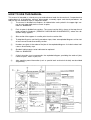


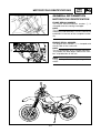
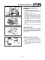

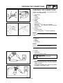
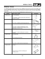
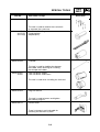


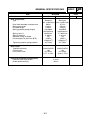
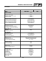
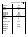
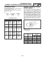

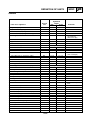
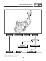
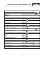
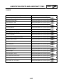

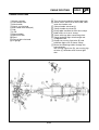


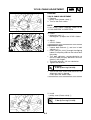
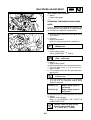

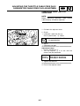
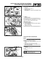


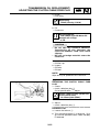

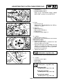

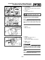
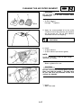


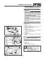
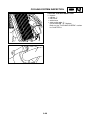
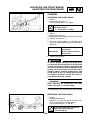


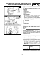
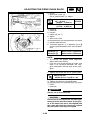
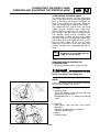
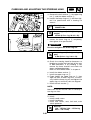

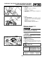

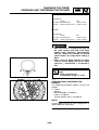

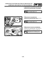

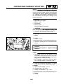


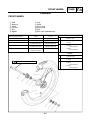
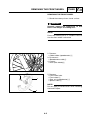


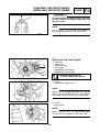

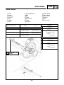
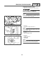
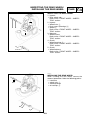
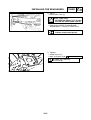


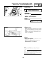

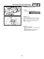

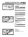


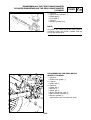
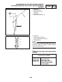
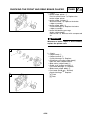
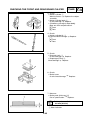
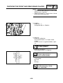
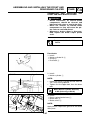

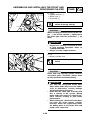

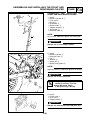


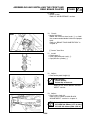

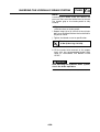
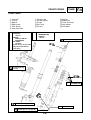
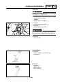
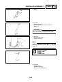
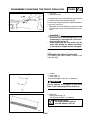

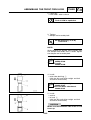
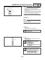
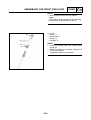


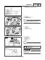
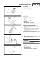
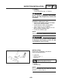


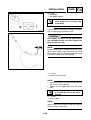
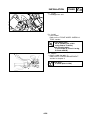
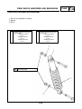


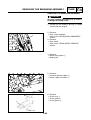

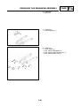
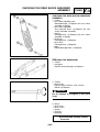

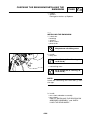


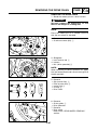
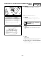
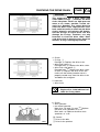


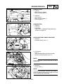
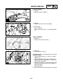
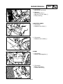


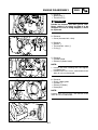

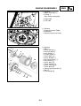
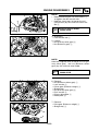


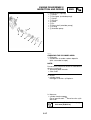
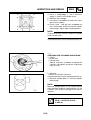
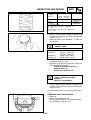


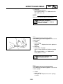
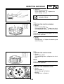
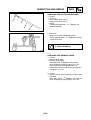
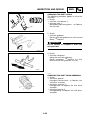
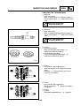
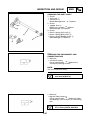

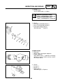
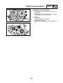


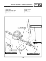
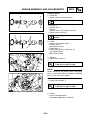
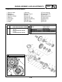


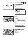

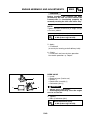
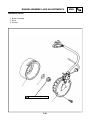


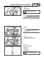
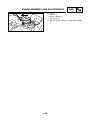

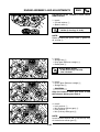


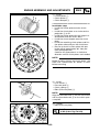


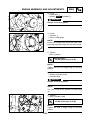
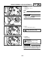
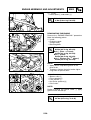
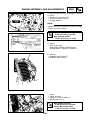
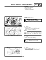


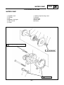

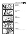

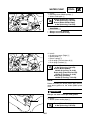

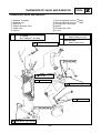


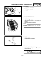
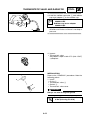
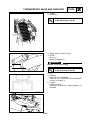
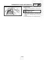


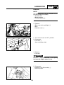
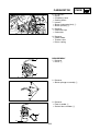
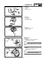
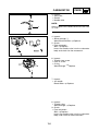
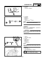


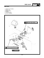


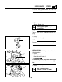


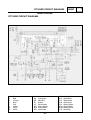


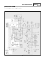
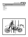
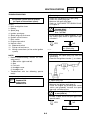
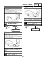

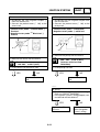
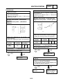


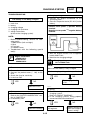
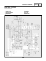


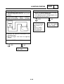


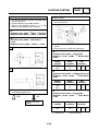


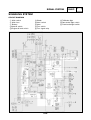
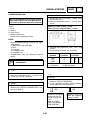


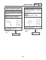
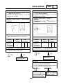
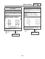


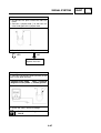

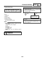
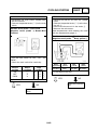

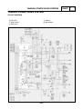

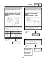
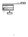
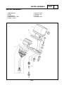

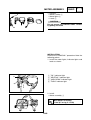
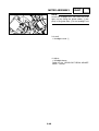


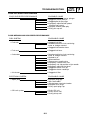
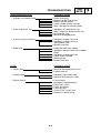
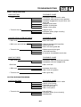
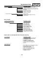
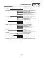


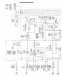
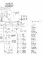


![Manuale Officina [ ITA ] Yamaha R1 2002-2003](http://vs1.manualzilla.com/store/data/006110674_1-52d32bbc9127defc0419b49b1226ec2b-150x150.png)