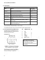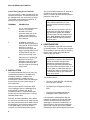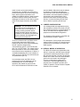
1
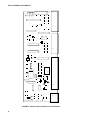
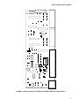
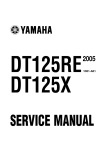
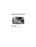
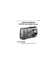
SDS-122 Serial Data Switch
5/99
C o p y r i g h t © 1 9 9 6 - 1 9 9 9
C a m p b e l l S c i e n t i f i c , I n c .
Warranty and Assistance
The SDS-122 SERIAL DATA SWITCH is warranted by CAMPBELL
SCIENTIFIC, INC. to be free from defects in materials and workmanship
under normal use and service for twelve (12) months from date of shipment
unless specified otherwise. Batteries have no warranty. CAMPBELL
SCIENTIFIC, INC.'s obligation under this warranty is limited to repairing or
replacing (at CAMPBELL SCIENTIFIC, INC.'s option) defective products.
The customer shall assume all costs of removing, reinstalling, and shipping
defective products to CAMPBELL SCIENTIFIC, INC. CAMPBELL
SCIENTIFIC, INC. will return such products by surface carrier prepaid. This
warranty shall not apply to any CAMPBELL SCIENTIFIC, INC. products
which have been subjected to modification, misuse, neglect, accidents of
nature, or shipping damage. This warranty is in lieu of all other warranties,
expressed or implied, including warranties of merchantability or fitness for a
particular purpose. CAMPBELL SCIENTIFIC, INC. is not liable for special,
indirect, incidental, or consequential damages.
Products may not be returned without prior authorization. The following
contact information is for US and International customers residing in countries
served by Campbell Scientific, Inc. directly. Affiliate companies handle
repairs for customers within their territories. Please visit
www.campbellsci.com to determine which Campbell Scientific company
serves your country. To obtain a Returned Materials Authorization (RMA),
contact CAMPBELL SCIENTIFIC, INC., phone (435) 753-2342. After an
applications engineer determines the nature of the problem, an RMA number
will be issued. Please write this number clearly on the outside of the shipping
container. CAMPBELL SCIENTIFIC's shipping address is:
CAMPBELL SCIENTIFIC, INC.
RMA#_____
815 West 1800 North
Logan, Utah 84321-1784
CAMPBELL SCIENTIFIC, INC. does not accept collect calls.
SDS-122 SERIAL DATA SWITCH
TABLE OF CONTENTS
PDF viewers note: These page numbers refer to the printed version of this document. Use
the Adobe Acrobat® bookmarks tab for links to specific sections.
1.
INTRODUCTION.........................................................................................................................1
2.
SPECIFICATIONS .....................................................................................................................1
2.1
2.2
2.3
Physical......................................................................................................................................1
Operational.................................................................................................................................2
Port Configuration/Connections.................................................................................................2
3. INSTALLATION ..............................................................................................................................4
4. CONFIGURATION .........................................................................................................................4
4.1
4.2
4.3
Jumper Configuration.................................................................................................................5
Special Modes of Operation ......................................................................................................5
Default Jumper Settings.............................................................................................................8
LIST OF FIGURES
1.
2.
3.
4.
5.
6.
General View of SDS-122 .....................................................................................................................1
Pin Positions for Datalogger Port: 9-way Male ‘D’ Type Connector .....................................................2
Pin Positions for Switched Datalogger Port ‘B’: 9-way Female ‘D’ Type Connector ............................3
Pin Positions for Switched RS232 Port ‘A’: 25-way Female ‘D’ Type Connector ..............................3
Default Jumper Positions on Circuit Board ...........................................................................................6
SDS-122 Settings for COM200 and SRM-6A (RAD Short Haul Modem).............................................7
LIST OF TABLES
1. Current Consumption in Various Modes/Communication Activity ........................................................2
This is a blank page.
SDS-122 SERIAL DATA SWITCH
The SDS-122 is a configurable two-way serial data switch which will allow two modem devices to be
connected to a datalogger simultaneously, so allowing both remote and local interrogation of the
datalogger to be carried out. It can support both DTE and DCE devices without the need for a null
modem cable, and can operate either in manual or automatic mode.
1. INTRODUCTION
The SDS-122 will normally be fitted in a
datalogger enclosure. It allows two modems
to be connected to a single datalogger at the
same time and can automatically switch the
datalogger to communicate with whichever
modem initiates communications.
The SDS-122 can support both DTE and DCE
devices without the need for a null modem
cable, and can emulate an SC932 (9-pin to
RS232-DCE) interface. One port of the SDS122 can also be configured to emulate an
optically isolated SC32A interface in either
DCE or DTE mode. A jumper switch is
provided for use with CR10/10X dataloggers
to block the transmission of synchronous
data.
The SDS-122 can be set either for fully
automatic mode, or manual mode, controlled
by a datalogger control port or any logic
signal. When in automatic mode, the SDS122 can be configured to either hold the last
port rung or to default to a specific port, when
communication finishes on either port.
2. SPECIFICATIONS
2.1 PHYSICAL
Length (over mounting lugs):
195mm
Width (over connectors):
75mm
Height:
22mm
Mounting Holes:
4.8mm dia. (0.1875in) at 177.8mm (7in)
spacing(suitable for mounting onto an
ENC 12/14 enclosure chassis plate)
Weight:
180g
FIGURE 1. General View of SDS-122
1
SDS-122 SERIAL DATA SWITCH
2.2 OPERATIONAL
TABLE 1. Current Consumption in Various Modes/Communication Activity
Mode
Activity
Current Drain
from Datalogger
Isolated
Quiescent (not communicating)
<75µA
Isolated
Communicating
Up to 3mA
Non-Isolated
No RAD-SRM modem connected and with no
communication activity (quiescent)
<100µA
Non-Isolated
RAD-SRM connected, waiting for call
2.5mA
Non-Isolated
RAD-SRM in comms. session but no communication
activity
9Ma
Non-Isolated
RAD-SRM communicating with PC208E or TCOM in
Monitor Mode
12mA
Non-Isolated
Jumper PL50 not fitted; RAD-SRM connected but no
communication activity. (This is the one-way, printenabled RAD-SRM mode.)
<100µA
Normal Operating Temperature Range: -25°C to +50°C
For extended temperature range requirements please contact Campbell Scientific.
2.3 PORT CONFIGURATION/CONNECTIONS
The SDS-122 has one datalogger port, one
switched datalogger port, a 25-way switched
RS232 port and a control port.
Datalogger Port
1
2
6
3
7
4
8
5
9
FIGURE 2. Pin Positions for Datalogger
Port: 9-way Male ‘D’ Type Connector
The datalogger port (marked ‘LOGGER’ in
Figure 1) is a 9-way male ‘D’ type connector,
having the following pin configuration:
2
PIN
ABBREVIATION
I/O
1
2
3
4
5
6
7
8
9
+5V
0V
RING
RX
ME
SDE/PE
CLK/HS
Not connected
TX
O
O
I
I
I
I
NOTE: When the datalogger is in
communication mode, pin 5 (ME –
Modem Enable) is held high. This line is
used by the SDS-122 to detect
communications and prevent switching to
the other port.
SDS-122 SERIAL DATA SWITCH
The switched datalogger port (marked ‘PORT
B’ in Figure 1) is a 9-way female ‘D’ type
connector, having the following pin
configuration:
Switched Datalogger Port B
5
4
9
3
8
2
7
1
6
FIGURE 3. Pin Positions for Switched
Datalogger Port ‘B’: 9-way Female ‘D’ Type
Connector
PIN
ABBREVIATION
I/O
1
2
3
4
5
6
7
8
9
+5V
0V
RING
RX
ME
SDE/PE
CLK/HS
Not connected
TX
I
I
O
O
O
O
25-Way Switched RS232 Port A
SERIAL I/O
13
1
25
14
FIGURE 4. Pin Positions for Switched RS232 Port ‘A’: 25-way Female ‘D’ Type Connector
The 25-way switched RS232 port (marked ‘RS232 PORT A’ in Figure 1) is a 25-way female ‘D’ type
connector, having the following pin configuration:
PIN
ABBREVIATION
1
2
3
4
5
6
7
15
20
Frame Ground
TX
RX
RTS
CTS
DSR
GND
External Power Supply
DTR
INPUT/OUTPUT
DTE
DCE
O
I
O
I
I
I
O
I
O
O
I
O
I
I
Other pins are not connected.
3
SDS-122 SERIAL DATA SWITCH
Control Port (3-way Screw Terminal)
The control port is a 3-way terminal block with
screwed connections. This terminal block can
be unplugged from the unit for ease of wiring.
The terminal connections are marked G, P
and M and are used as follows:
TERMINAL
CONNECTION
G
0V – It is recommended that
a wire is run from this
terminal to the main
protective earth point in the
system to give maximum
protection from interference
and transients.
P
In MANUAL mode, this
terminal can be pulled high to
select port B. In AUTO mode,
when PL41 is fitted, it
functions as an output and
will go logic high when port B
is being used or logic low
when port A is being used.
M
wire is connected between the ‘G’ terminal of
the SDS-122 and the system protective
ground, to ensure optimum internal transient
protection of the device.
CAUTION: Although the SDS-122 has
built-in transient protection, it is not
protected against secondary lightning
damage.
Devices that are connected to port A or
port B which are likely to be subject to
large transients should have external
protection fitted. For long cable runs on
port A, RAD-SRM Short Haul modems
fitted with RAD-SP lightning arrestors
should be used.
4. CONFIGURATION
The configuration of the SDS-122 is defined
by internal jumpers. To access these jumpers
it is necessary to open the case by removing
the four case screws and pulling the two
halves of the case apart.
When this line is pulled high,
the SDS-122 will be in
MANUAL mode and only the
port that is selected by the
user (by using the P terminal)
will be active.
CAUTION: Before touching any
components or jumpers, take precautions
against electrostatic damage when
handling the exposed circuit board –
either by using an ESD protection earth
strap connected to the sensor case, or, at
the very least, by making sure that you
discharge any static by touching the case
or metal shell of the 'D' type connectors
on the circuit board.
3. INSTALLATION
You should install the SDS-122 in a dry, noncondensing environment. The ENC12/14
datalogger enclosure, available from
Campbell Scientific, provides an ideal
environment for both a CR10/10X datalogger
and the SDS-122, plus a power supply or
other equipment.
Use one SC12 cable to connect the SDS122’s ‘datalogger’ port to a datalogger port,
and a second to connect port ‘B’ to a
compatible modem. A computer/short haul
modem can be connected to port ‘A’ using a
standard RS232 cable.
Normally, for most applications, there will be
no need for a connection to be made between
the 3-way terminal block on the SDS-122 and
the datalogger, unless direct measurements
of the switch status, or manual control is
required. It is recommended that a ground
4
The jumpers control:
•
The way in which the SDS-122 switches
from one port to another
•
The RS232 port configuration (DCE or
DTE)
•
The degree of isolation between the
datalogger and the RS232 device.
It is important to understand the different
methods of isolation, as this can affect the
accuracy of measurements made by the
datalogger. In permanent installations it is
good practice to ensure that the datalogger
ground and computer ground are isolated,
otherwise ground loops and digital noise could
SDS-122 SERIAL DATA SWITCH
result in errors on low-level analogue
measurements. The SDS-122 can be set to
provide opto-isolation to prevent such ground
loops, but this mode of operation is not
suitable for all RS232 devices, either because
the device needs to source power from the
datalogger or because it is not able to provide
power to the output electronics of the SDS122.
power available. When this mode is enabled,
no isolation is provided by the SDS-122.
Some devices, such as the RAD-SRM short
haul modem, and most telephone modems
provide their own isolation barrier. Care
should be taken when selecting third party
devices to ensure that they provide some
form of barrier to prevent ground loops.
4.1 JUMPER CONFIGURATION
WARNING: The opto-isolation provided
by the SDS-122 is not designed, nor
should it be used, for the purpose of
providing a safety protection barrier.
Internal protection devices will cause a
breakdown of the isolation if the potential
difference between the datalogger and
RS232 ground exceeds 47V.
To work in isolated mode, the RS232 device
must provide power to the SDS-122 by
holding at least one of the input handshaking
lines at a positive voltage during
communications (pins 4 or 20 in DCE mode,
pins 5 or 6 in DTE mode). The voltage input to
these lines must be <9V or be current limited
to an effective source impedance of 1Kohm. If
a suitable handshaking line is not available, a
power source (6-20V) can be connected to pin
15 (referenced to pin 7G).
In non-isolated mode, the SDS-122 can
provide power from the datalogger via the
handshaking lines, to power external
interfaces. See details on jumpers PL50,
PL51 and PL56 below for information on the
It is envisaged that most applications will be
with a telephone modem connected to Port B
and a personal computer connected directly to
Port A. The SDS-122, as supplied, has its
jumpers set to this default configuration.
The locations of the jumpers on the SDS-122
circuit board are shown in Figure 5.
The description of each jumper and its default
setting is given in Section 4.3. Note that some
jumpers work in combination to achieve the
state required.
4.2 SPECIAL MODES OF OPERATION
The SDS-122 contains a programmable chip,
which, in conjunction with the jumper settings
(see Section 4) determines the way in which
the ports are selected. Currently, the program
allows one or other of the two communication
ports to be connected to the datalogger.
There is no state where neither port is
connected. For special applications, the
program can be modified to provide other
modes of operation. Please contact Campbell
Scientific for more details.
5
SDS-122 SERIAL DATA SWITCH
OPEN
OPEN
OPEN
OPEN
C109
R44
PL41
PL42
PL43
PL44
R123
R147
R124
R122
R121
U1
R142
R47
D24
R14
CONN1
R130
U6
IC1
R150
D8
C108
UB1
R43
R149
C101
R126
U8
R141
R117
R118
CONN3
R120
R119
U7
R151
D21
U4
R16
R17
D22
C110
PL56 OPEN
R145
R18
D17
R7
R13
U2
2
D16
3
D23
5
6
R148
1
7
R144
10
SW6-10
DCE
D10
ISOLATED
R8
C3
D15
DTE
SW1-5
D20
CLOSED
8
9
4
PL50
Q6
PL51 OPEN
POWERED
D19
D18
C111
D4
C5
R20
Q3
C112
C7
FS1
ZD1
CONN2
U5
C6
R15
R9
U3
Q5
R31
C107
R36
R38
C113
CSL20026
CONN4
R46
R39
ISS 1
C106
FIGURE 5. Default Jumper Positions on Circuit Board
6
SDS-122 SERIAL DATA SWITCH
OPEN
OPEN
OPEN
OPEN
C109
R44
PL41
PL42
PL43
PL44
R123
R147
R124
R122
R121
U1
R142
R47
D24
R14
CONN1
R130
U6
IC1
R150
D8
C108
UB1
R43
R149
C101
R126
U8
R141
R117
R118
CONN3
R120
R119
U7
R151
D21
U4
R16
R17
D22
C110
PL56 OPEN
R145
R18
D17
R7
R13
U2
D15
DCE
D10
SW6-10
D23
6
R148
7
R144
10
PL50
Q6
9
PL51 OPEN
POWERED
5
1
4
DTE
SW1-5
D20
CLOSED
8
3
DTE
CHANGE TO
POWER
TURN 180”
R8
ISOLATED
2
CHANGE TO
C3
TURN 180”
D16
D19
D18
C111
D4
C5
R20
Q3
C112
C7
FS1
ZD1
CONN2
U5
C6
R15
R9
U3
Q5
R31
C107
R36
R38
C113
CSL20026
CONN4
R46
R39
ISS 1
C106
FIGURE 6. SDS-122 Settings for COM200 and SRM-6A (RAD Short Haul Modem)
7
SDS-122 SERIAL DATA SWITCH
4.3 DEFAULT JUMPER SETTINGS
JUMPER
DEFAULT
DESCRIPTION
PL41
Not fitted
When jumper PL41 is fitted, port A/B on the 3-way screw
terminal will output 0V for switch on port A, or 5V for switch on
port B when the SDS-122 is in AUTO mode only. When the
jumper is not fitted, or the unit is in MANUAL mode, then the line
becomes an input.
PL42
Not fitted
When jumper PL42 is fitted the SDS-122 will default to the port
selected by PL43 when the ME line goes low. When the jumper
is not fitted, the unit will stay with the last port used after the ME
line goes low.
PL43
Not fitted
This jumper works in combination with jumper PL42. When
jumper PL43 is fitted and jumper PL42 is also fitted, the SDS-122
will revert to port B when the ME line goes low. When PL43 is not
fitted, but PL42 is fitted, the unit will default to port A when the
ME line goes low.
PL44
Not fitted
When jumper PL44 is fitted and synchronous data is transmitted,
(e.g. to a storage module), the SDS-122 will block any data
output to port A. When PL44 is not fitted all data is allowed to
pass through to port A.
SW1-5
DCE
Jumper block SW1-5 can be set so that port A can emulate
either a DCE or DTE interface, and so there is no requirement for
a null modem cable. The ‘DCE’ and ‘DTE’ jumper positions are
marked on the PCB. Note that, to change the settings, the whole
jumper block is removed and re-inserted at 180°. The red line on
the jumper block should be adjacent to the state (DCE or DTE)
required.
SW6-10
Isolated
Jumper block 6-10 can be set so that port A is either optically
isolated or powered. RAD- SRM short haul modems would be
driven in the powered mode. ‘Isolated’ and ‘Powered’ positions
are marked on the PCB. Note that, to change the settings, the
whole jumper block is removed and re-inserted at 180°. The red
line on the jumper block should be adjacent to the state (Isolated
or Powered) required.
PL50
Fitted
When jumper PL50 is fitted, not less than 4.3V is supplied to pins
20 and 4 of port A in DTE mode and to pins 5 and 6 of port A in
DCE mode. RAD-SRM modems in interactive communications
would need the PL50 jumper to be fitted. The actual voltage
supplied to the pins will depend on the setting of jumper PL51
(see below). When the jumper is not fitted, no voltage is
supplied. This has no effect in isolated mode.
PL51
Not fitted
When jumper PL51 is fitted, >7V is permanently output to pins 20
and 4 of port A in DTE mode and to pins 5 and 6 of port A in
DCE mode. This jumper is not normally fitted for RAD-SRM
modems in interactive communication. When not fitted the
outputs are shut off when ME goes low.
PL56
Not fitted
When jumper PL56 is fitted, >7V is supplied to the handshake
lines (pins 20 and 4 of port A in DTE mode and pins 5 and 6 of
port A in DCE mode) when either ME or SDE/PE goes high.
When jumper PL56 is not fitted, 7V will only be applied when ME
is high. This has no effect in isolated mode.
8
This is a blank page.
Campbell Scientific Companies
Campbell Scientific, Inc. (CSI)
815 West 1800 North
Logan, Utah 84321
UNITED STATES
www.campbellsci.com
[email protected]
Campbell Scientific Africa Pty. Ltd. (CSAf)
PO Box 2450
Somerset West 7129
SOUTH AFRICA
www.csafrica.co.za
[email protected]
Campbell Scientific Australia Pty. Ltd. (CSA)
PO Box 444
Thuringowa Central
QLD 4812 AUSTRALIA
www.campbellsci.com.au
[email protected]
Campbell Scientific do Brazil Ltda. (CSB)
Rua Luisa Crapsi Orsi, 15 Butantã
CEP: 005543-000 São Paulo SP BRAZIL
www.campbellsci.com.br
[email protected]
Campbell Scientific Canada Corp. (CSC)
11564 - 149th Street NW
Edmonton, Alberta T5M 1W7
CANADA
www.campbellsci.ca
[email protected]
Campbell Scientific Ltd. (CSL)
Campbell Park
80 Hathern Road
Shepshed, Loughborough LE12 9GX
UNITED KINGDOM
www.campbellsci.co.uk
[email protected]
Campbell Scientific Ltd. (France)
Miniparc du Verger - Bat. H
1, rue de Terre Neuve - Les Ulis
91967 COURTABOEUF CEDEX
FRANCE
www.campbellsci.fr
[email protected]
Campbell Scientific Spain, S. L.
Psg. Font 14, local 8
08013 Barcelona
SPAIN
www.campbellsci.es
[email protected]
Please visit www.campbellsci.com to obtain contact information for your local US or International representative.