
1
2005
BT1100
5JN4-AE1
SUPPLEMENTARY
SERVICE MANUAL
FOREWORD
This Supplementary Service Manual has been prepared to introduce new service and data for the Yamaha
BT1100 (2005).
For complete service information procedures it is necessary to use this Supplementary Service Manual together with the following manuals.
BT1100 SERVICE MANUAL: 5JN1-AE1
BT1100 2005
SUPPLEMENTARY SERVICE MANUAL
© 2004 by Yamaha Motor Italia S.p.A.
First edition, September 2004
All rights reserved. Any reproduction or
unauthorized use without the written
permission of Yamaha Motor Italia S.p.A.
is expressly prohibited.
Printed in Italy
NOTICE
This manual was produced by the Yamaha Motor Italia S.p.A. primarily for use by Yamaha dealers and
their qualified mechanics. It is not possible to include all the knowledge of a mechanic in one manual, so
it is assumed that anyone who uses this book to perform maintenance and repairs on Yamaha motorcycles has a basic understanding of the mechanical ideas and the procedures of motorcycle repair. Repairs
attempted by anyone without this knowledge are likely to render the motorcycle unsafe and unfit for use.
Yamaha Motor Italia S.p.A. is continually striving to improve all its models. Modifications and significant
changes in specifications or procedures will be forwarded to all authorized Yamaha dealers and will appear in future editions of this manual where applicable.
NOTE:
Designs and specifications are subject to change without notice.
IMPORTANT INFORMATION
Particularly important information is distinguished in this manual by the following notations.
The Safety Alert Symbol means ATTENTION! BECOME ALERT! YOUR SAFETY IS INVOLVED!
WARNING
CAUTION:
NOTE:
Failure to follow WARNING instructions could result in severe injury or death to
the motorcycle operator, a bystander or a person inspecting or repairing the motorcycle.
A CAUTION indicates special precautions that must be taken to avoid damage
to the motorcycle.
A NOTE provides key information to make procedures easier or clearer.
EAS00007
HOW TO USE THIS MANUAL
This manual is intended as a handy, easy-to-read reference book for the mechanic. Comprehensive explanations of all installation, removal, disassembly, assembly, repair and check procedures are laid out
with the individual steps in sequential order.
1 The manual is divided into chapters. An abbreviation and symbol in the upper right corner of each page
indicate the current chapter.
Refer to "SYMBOLS".
2 Each chapter is divided into sections. The current section title is shown at the top of each page, except
in Chapter 3 ("PERIODIC CHECKS AND ADJUSTMENTS"), where the sub-section title(s) appears.
3 Sub-section titles appear in smaller print than the section title.
4 To help identify parts and clarify procedure steps, there are exploded diagrams at the start of each removal and disassembly section.
5 Numbers are given in the order of the jobs in the exploded diagram. A circled number indicates a disassembly step.
6 Symbols indicate parts to be lubricated or replaced.
Refer to "SYMBOLS".
7 A job instruction chart accompanies the exploded diagram, providing the order of jobs, names of parts,
notes in jobs, etc.
8 Jobs requiring more information (such as special tools and technical data) are described sequentially.
1
ILLUSTRATED SYMBOLS
2
GEN
INFO
SPEC
3
4
INSP
ADJ
ENG
5
6
CARB
CHAS
7
8
TRBL
SHTG
ELEC
9
0
q
w
e
r
t
y
u
i
o
p
a
s
d
The following symbols are not relevant to every
vehicle.
Illustrated symbols 1 to 8 are printed on the top
right of each page and indicate the subject of
each chapter.
1 General information
2 Specifications
3 Periodic inspections and adjustments
4 Engine
5 Carburetor
6 Chassis
7 Electrical system
8 Troubleshooting
?
f
New
Illustrated symbols 9 to y are used to identify
the specifications appearing in the text.
9 Can be serviced with engine mounted
0 Filling fluid
q Lubricant
w Special tool
e Torque
r Wear limit, clearance
t Engine speed
y Electrical data
Illustrated symbols u to s in the exploded diagrams indicate the types of lubricants and lubrication points.
u Apply engine oil
i Apply gear oil
o Apply molybdenum disulfide oil
p Apply wheel bearing grease
a Apply lightweight lithium-soap base grease
s Apply molybdenum disulfide grease
Illustrated symbols d to f in the exploded diagrams indicate the following:
d Apply locking agent (LOCTITE®)
f Replace the part
CONTENTS
SPECIFICATIONS
GENERAL SPECIFICATIONS....................................................................................
MAINTENANCE SPECIFICATIONS – ENGINE ........................................................
LUBRICATION CHART ..............................................................................................
TIGHTENING TORQUES – ENGINE ........................................................................
MAINTENANCE SPECIFICATIONS – CHASSIS ......................................................
TIGHTENING TORQUES – CHASSIS ......................................................................
MAINTENANCE SPECIFICATIONS – ELECTRICAL ................................................
GENERAL TORQUE SPECIFICATIONS ..................................................................
CONVERSION TABLE ..............................................................................................
LUBRICATION POINTS AND LUBRICANT TYPES ..................................................
LUBRICATION DIAGRAMS ......................................................................................
CABLE ROUTING ......................................................................................................
1
4
10
11
14
16
18
20
20
21
23
26
PERIODIC INSPECTIONS AND ADJUSTMENTS
PERIODIC MAINTENANCE/LUBRICATION INTERVALS ........................................
CHASSIS – ADJUSTING THE FRONT BRAKE ........................................................
CHECKING THE FUSES ..........................................................................................
29
31
32
ENGINE
ENGINE REMOVAL ..................................................................................................
34
CARBURETION
CARBURETOR ..........................................................................................................
36
CHASSIS
FRONT BRAKE MASTER CYLINDER ......................................................................
FRONT BRAKE CALIPERS ......................................................................................
HANDLEBAR..............................................................................................................
STEERING HEAD – LOWER BRACKET ..................................................................
37
39
41
45
ELECTRICAL
ELECTRICAL COMPONENTS .................................................................................. 47
SWITCHES ................................................................................................................ 49
CHECKING THE BULBS AND BULB SOCKETS ...................................................... 52
IMMOBILIZER SYSTEM ............................................................................................ 55
SELF-DIAGNOSIS DEVICE ...................................................................................... 63
IGNITION SYSTEM.................................................................................................... 68
ELECTRIC STARTING SYSTEM .............................................................................. 73
CHARGING SYSTEM ................................................................................................ 83
LIGHTING SYSTEM .................................................................................................. 86
SIGNALING SYSTEM ................................................................................................ 91
FUEL PUMP SYSTEM .............................................................................................. 99
CARBURETOR HEATER SYSTEM .......................................................................... 104
TROUBLESHOOTING
STARTING FAILURE/HARD STARTING.................................................................... 107
WIRING DIAGRAM
GENERAL SPECIFICATIONS
SPEC
SPECIFICATIONS
GENERAL SPECIFICATIONS
Item
Standard
Model code:
BT1100: 5JN4
Dimensions:
Overall length
Overall width
Overall height
Seat height
Wheelbase
Ground clearance
Minimum turning radius
2,200 mm
800 mm
1,140 mm
812 mm
1,530 mm
168 mm
2,980 mm
Weight:
Dry (without oil and fuel)
Wet (with oil and a full fuel tank)
Bias weight (dry) front
Bias weight (dry) rear
Bias weight (wet) front
Bias weight (wet) rear
Maximum load-except motorcycle:
233 kg
254 kg
109.5 kg
123.5 kg
122 kg
132 kg
200 kg
Engine:
Engine type
Air cooled 4-stroke,
SOHC
V-type 2-cylinder
1,063 L
95 75 mm
8.3 : 1
1,000 kPa (10 kg/cm2, 10 bar) at 400 r/min
Electric starter
Cylinder arrangement
Displacement
Bore stroke
Compression ratio
Compression pressure (STD)
Starting system
Lubrication system:
Engine oil:
Type
Temp.
Wet sump
SAE20W40SE or SAE10W30SE
°C
Recommended engine oil classification:
API Service SE, SF, SG or higher
Final gear oil:
Hypoid gear oil SAE 80 (API GL4)
Oil quantity:
Engine oil
Periodic oil change
With oil filter replacement
Total amount
Final gear case oil
Total amount
3.0 L
3.1 L
3.6 L
0.2 L
1
GENERAL SPECIFICATIONS
Item
Standard
Air filter:
Dry type element
Fuel:
Type
Fuel tank capacity
Fuel reserve amount
Regular unleaded gasoline
20 L
5.8 L
Carburetor:
Type/quantity
Manufacturer
BSR37/2
MIKUNI
Spark plug:
Type
Manufacturer
Spark plug gap
BPR7ES/W22EPR-U
NGK/DENSO
0.7 0.8 mm
Clutch type:
Wet, multiple-disc
Transmission:
Primary reduction system
Primary reduction ratio
Secondary reduction system
Secondary reduction ratio
Transmission type
Operation
Gear ratio
Spur gear
78/47 (1.660)
Shaft drive
44/47 19/18 32/11 (2.875)
Constant mesh 5-speed
Left foot operation
40/17 (2.353)
40/24 (1.667)
36/28 (1.286)
32/31 (1.032)
29/34 (0.853)
1st
2nd
3rd
4th
5th
Chassis:
Frame type
Caster angle
Trail
Tire:
Type
Size
Manufacturer
Type
SPEC
Twin tube Backbone
25°
106 mm
Tubeless
120/70-ZR17 (58W)
170/60-ZR17 (72W)
DUNLOP / METZELER
DUNLOP / METZELER
D205F TL / MEZ3F TL
D205 TL / MEZ3 TL
front
rear
front
rear
front
rear
Tire pressure (cold tire):
0 ~ 90 kg load *
front
rear
90 kg (198 lb) ~ Maximum load * front
rear
230 kPa (2.30 kg/cm2) (2.30 bar)
250 kPa (2.50 kg/cm2) (2.50 bar)
250 kPa (2.50 kg/cm2) (2.50 bar)
270 kPa (2.70 kg/cm2) (2.70 bar)
* Load is the total weight of the cargo, rider,
passenger and accessories.
Maximum load:
200 kg (total weight of rider, passenger,
cargo and accessories)
2
GENERAL SPECIFICATIONS
Item
Brake:
Front brake
Rear brake
SPEC
Standard
type
operation
type
operation
Dual disc brake
Right hand operation
Single disc brake
Right foot operation
Suspension:
Front suspension
Rear suspension
Telescopic fork
Swingarm (link suspension)
Shock absorber:
Front shock absorber
Rear shock absorber
Coil spring/Oil damper
Coil spring/Gas-oil damper/Spring preload
adjustable
Wheel travel:
Front wheel travel
Rear wheel travel
130 mm
113 mm
Electrical system:
Ignition system
Generator system
Battery type
Battery capacity
T.C.I. (digital)
A.C. magneto
GT14B-4
12V 12Ah
Headlight type:
Quartz bulb (halogen)
Bulb voltage, wattage x quantity:
Headlight
Auxiliary light
Tail/brake light
License plate light
Front turn signal indicator light
Rear turn signal indicator light
Meter lighting
Neutral indicator light
Turn signal light
Oil level warning light
High beam indicator light
Fuel level warning light
Immobilizer system light
12 V 60 W/55 W x 1
12 V 5 W x 1
12 V 5 W / 21 W x 1
12 V 5 W x 1
12 V 10 W x 2
12 V 10 W x 2
LED x 12
LED x 1
LED x 1
LED x 1
LED x 1
LED x 1
LED x 1
3
MAINTENANCE SPECIFICATIONS
SPEC
MAINTENANCE SPECIFICATIONS
ENGINE
Item
Standard
Limit
Cylinder head:
Volume
Warp limit
57.0 58.4 cm3
•••
•••
0.03 mm
Cylinder:
Bore size
Measuring point
Max. out of round
95.00 95.01 mm
40 mm
•••
95.1 mm
•••
0.01 mm
Chain drive (left & right)
25.000 25.021 mm
24.96 24.98 mm
0.020 0.061 mm
•••
•••
•••
•••
39.112 39.212 mm
#1: 32.093 32.193 mm
#2: 32,127 32.227 mm
7.162 mm
39.145 39.245 mm
32.200 32.300 mm
7.195 mm
•••
39.012 mm
#1: 31.993 mm
#2: 32.027 mm
7.012 mm
39.045 mm
32.100 mm
7.045 mm
0.03 mm
Camshaft:
Drive method
Cam cap inside diameter
Camshaft outside diameter
Shaft-to-cap clearance
Cam dimensions:
Intake
Exhaust
Camshaft runout limit
“A”
“B”
“C”
“A”
“B”
“C”
4
MAINTENANCE SPECIFICATIONS
Item
SPEC
Standard
Limit
Timing chain:
Timing chain type/No. of links
Timing chain adjustment method
SILENT 98L
Automatic
•••
•••
Rocker arm/rocker arm shaft:
Bearing inside diameter
Shaft outside diameter
Arm-to-shaft clearance
14.000 mm 14.018 mm
13.985 mm 13.991 mm
0.009 mm 0.033 mm
14.036 mm
13.95 mm
0.086 mm
Valve, valve seat, valve guide:
Valve clearance (cold)
IN
EX
0.07 0.12 mm
0.12 0.17 mm
•••
•••
Valve dimensions:
Head Diameter
“A” head diameter
“B” face width
“C” seat width
“D” margin thickness
Stem outside diameter
Guide inside diameter
Stem-to-guide clearance
Face Width
IN
EX
IN
EX
IN
EX
IN
EX
IN
EX
IN
EX
IN
EX
Seat Width
47.0 47.2 mm
39.0 39.2 mm
2.1 mm
2.1 mm
1.2 1.4 mm
1.2 1.4 mm
1.1 1.5 mm
1.1 1.5 mm
7.975 7.990 mm
7.960 7.975 mm
8.000 8.012 mm
8.000 8.012 mm
0.010 0.037 mm
0.025 0.052 mm
5
Margin Thickness
•••
•••
•••
•••
1.8 mm
1.8 mm
0.8 mm
0.8 mm
7.955 mm
7.935 mm
8.042 mm
8.042 mm
0.08 mm
0.10 mm
MAINTENANCE SPECIFICATIONS
Item
SPEC
Standard
Stem runout limit
Limit
•••
0.03 mm
IN
EX
1.2 1.4 mm
1.2 1.4 mm
2.0 mm
2.0 mm
IN
EX
IN
EX
IN
EX
IN
EX
IN
EX
IN
EX
44.6 mm
44.6 mm
40 mm
40 mm
160.7 N (16.4 kg)
160.7 N (16.4 kg)
35.28 N/mm (3.6 kgf/mm)
35.28 N/mm (3.6 kgf/mm)
45.37 N/mm (4.63 kgf/mm)
45.37 N/mm (4.63 kgf/mm)
•••
•••
43.5 mm
43.5 mm
•••
•••
•••
•••
•••
•••
•••
•••
2.5°/1.9 mm
2.5°/1.9 mm
IN
EX
Clockwise
Clockwise
•••
•••
Piston:
Piston to cylinder clearance
Piston size “D”
0.025 0.050 mm
94.960 94.975 mm
0.15 mm
•••
Measuring point “H”
Piston off-set
Piston pin bore inside diameter
Piston pin outside diameter
5 mm
0 mm
22.004 22.015 mm
21.991 22.000 mm
•••
•••
22.045
21.975
Valve seat width
Valve spring:
Free length
Set length (valve closed)
Compressed pressure (installed)
Spring rate (K1)
Spring rate (K2)
Tilt limit
Direction of winding
(top view)
6
MAINTENANCE SPECIFICATIONS
Item
SPEC
Standard
Limit
Piston rings:
Top ring:
Type
Dimensions (B x T)
End gap (installed)
Side clearance (installed)
2nd ring:
Plain
1.5 3.8 mm
0.3 0.5 mm
0.04 0.08 mm
•••
•••
0.8 mm
0.1 mm
Type
Dimensions (B x T)
End gap (installed)
Side clearance
Oil ring:
Taper
1.2 3.8 mm
0.30 0.45 mm
0.03 0.07 mm
•••
•••
0.8 mm
0.1 mm
2.5 3.4 mm
0.2 0.7 mm
•••
•••
0.044 0.073 mm
1 Blue 2 Black 3 Brown
4 Green 5 Yellow
•••
•••
101.95 102.00 mm
•••
0.320 0.474 mm
•••
0.02 mm
•••
Dimensions (B x T)
End gap (installed)
Connecting rod:
Oil clearance
Color code (corresponding size)
Crankshaft:
Crank width “A”
Runout limit “C”
Big end side clearance “D”
7
MAINTENANCE SPECIFICATIONS
Item
SPEC
Standard
Limit
Clutch:
Friction plate thickness
Quantity
Clutch plate thickness
Quantity
Clutch plate thickness
Quantity
Clutch spring free length
Quantity
Clutch housing thrust clearance
Clutch housing radial clearance
Clutch release method
Push rod bending limit
2.9 3.1 mm
8
2.5 2.7 mm
1
1.9 2.1 mm
7
7.2 mm
1
0.05 0.40 mm
0.010 0.044 mm
Inner push, screw push
•••
2.8
•••
0.1
•••
0.1
•••
6.5
•••
•••
•••
•••
0.5
Transmission:
Main axle deflection limit
Drive axle deflection limit
•••
•••
0.08 mm
0.08 mm
Shifter:
Shifter type
Shift fork thickness
Guide bar
5.76 5.89 mm
•••
•••
5JN4 10
#1: #128.8 - #2: #127.5
#55
5DL49-3
P-0M (826)
#63.8
#142.5
1.0
#17.5
0.8
0.8
0.8
3.0
1.2
#45
0,9
#125
11 12 mm
950 1.050 r/min
4 5%
32.2 33.6 kPa (-242 -252 mmHg)
75 85 °C
•••
•••
•••
•••
•••
•••
•••
•••
•••
•••
•••
•••
•••
•••
•••
•••
•••
•••
•••
•••
•••
•••
Electrical type
UC-Z61B/MITSUBISHI
0.8 A
12 kPa (0.12 kf/cm2)
•••
•••
•••
Carburetor:
I. D. mark
Main jet
Main air jet
Jet needle
Needle jet
Pilot air jet
Pilot outlet
Pilot jet
Bypass 1
Bypass 2
Bypass 3
Pilot screw
Valve seat size
Starter jet
Starter jet
Throttle valve size
Float height
Engine idle speed
CO%
Intake vacuum
Engine oil temperature
Fuel pump:
Type
Model/manufacturer
Consumption amperage
Output pressure
(M.J)
(M.A.J)
(J.N)
(N.J)
(P.A.J.1)
(P.A.J.2)
(P.O)
(P.J)
(B.P.1)
(B.P.2)
(B.P.3)
(P.S)
(V.S)
(G.S.1)
(G.S.2)
(TH.V)
(F.H)
<max>
8
mm
mm
mm
mm
mm
MAINTENANCE SPECIFICATIONS
Item
SPEC
Standard
Limit
Lubrication system:
Oil filter type
Oil pump type
Tip clearance “A” or “B”
Side clearance
Bypass valve opening pressure
Relief valve operating pressure
Paper type
Trochoid type
0.03 0.09 mm
0.03 0.08 mm
80 120 kPa (0.8 ~ 1.2 kgf/cm2)
450 550 kPa (4.5 5.5 kgf/cm2)
•••
•••
0.15 mm
0.15 mm
•••
•••
Shaft drive:
Middle gear backlash
Final gear backlash
0.1 0.2 mm
0.1 0.2 mm
•••
•••
9
SPEC
MAINTENANCE SPECIFICATIONS
Item
Standard
Lubrication chart:
Needle bearing (starter)
Connecting rod big end
Main axle
Drive axle
Crankshaft
Pressure feed
Pinin drive
Splashed
Orifice
Rocker arm (EX)
Camshaft (EX)
Middle driveshaft
Rocker arm (EX)
Rocker arm (IN)
Camshaft (IN)
Rocker arm (IN)
Oil filter
Relief valve
Oil pan
10
Oil pump
MAINTENANCE SPECIFICATIONS
SPEC
Cylinder head tightening sequence:
Crankcase tightening sequence:
Left crankcase
Right crankcase
11
MAINTENANCE SPECIFICATIONS
SPEC
Tightening torques
Part to be tightened
Cylinder head
Cylinder head
Plate
Cylinder head cover
Cylinder head (exhaust pipe)
Rocker arm shaft
Camshaft sprocket cover
Tappet cover
Rocker arm shaft
(oil passage)
Stopper plate (camshaft)
Spark plug
Cylinder
Lower cylinder head cover
Upper cylinder head cover
Connecting rod
Rotor
Valve adjusting locknut
Camshaft sprocket
Timing chain tensioner
Timing chain tentioner cap
Timing chain guide
Oil pump
Oil strainer cover
Oil filter cover
Oil pump gear
Oil pump cap
Oil delivery pipe
(cylinder head)
(crankcase)
Oil drain bolt
Air filter:
Air filter cover fastener
Carburetor cover fastener
A.I.S. system:
A.I.S. system fastener
(pump and piping)
A.I.S. system pipe fastener
to engine starter
A.I.S. pump fastener
to A.I.S. bracket
Exhaust system:
Cylinder head and exhaust pipe joint
Exhaust pipe bracket
Exhaust pipe/exhaust pipe
guard fastener (rear)
Exhaust pipe strap
Silencer fastener to passenger
board support
Exhaust pipe guard fastener
Part
name
Thread
size
Q’ty
Tightening
torque
N·m
m·kg
Nut
Nut
Bolt
Screw
Stud bolt
Union
bolt
Bolt
Bolt
Bolt
M12
M10
M8
M6
M8
M16
8
2
2
4
4
2
50
35
20
4
12.5
37.5
5.0
3.5
2.0
0.4
1.25
3.75
M6
M6
M16
4
8
4
10
10
38
1.0
1.0
3.8
Bolt
M8
4
20
2.0
–
Bolt
Bolt
Screw
Nut
Nut
Nut
Bolt
Bolt
Bolt
Bolt
Bolt
Bolt
Bolt
Bolt
Bolt
Union
bolt
Union
bolt
–
M14
M6
M6
M6
M9
M16
M8
M10
M6
M6
M6
M6
M6
M6
M6
M6
M16
2
2
6
8
4
1
4
2
4
2
4
3
3
5
1
1
2
20
10
10
5
48
175
27
55
10
8
10
10
10
10
12
10
20
2.0
1.0
1.0
0.5
4.8
17.5
2.7
5.5
1.0
0.8
1.0
1.0
1.0
1.0
1.2
1.0
2.0
M10
1
20
2.0
M14
1
43
4.3
Screw
Screw
M5
M5
2
4
2
4.5
0.2
0.45
Screw
M6
4
10
1.0
Screw
M6
1
10
1.0
Screw
M5
2
8
0.8
Nut
Screw
M8
M8
4
2
20
25
2.0
2.5
Screw
Screw
M8
M8
2
3
20
18
2.0
1.8
Screw
Screw
M10
M6
2
2
47
7
4.7
0.7
12
Remarks
Use lock
washer
MAINTENANCE SPECIFICATIONS
Part to be tightened
Crankcase (cylinder)
Crankcase (cylinder)
Crankcase
Crankcase
Bearing retainer (middle drive pinion gear)
Crankcase cover (left)
Crankcase cover (right)
Clamp
One-way clutch
Primary drive gear
Clutch spring
Clutch adjuster
Clutch boss
Push lever axle
Middle drive pinion gear
Bearing retainer (middle driven shaft)
Yoke (middle driven shaft)
Bearing housing (middle drive shaft)
Shift lever stopper
Part
name
Thread
size
Q’ty
SPEC
Tightening
torque
N·m
m·kg
Stud bolt
Stud bolt
Bolt
Bolt
Bolt
Bolt
Bolt
Bolt
Bolt
Nut
M12
M10
M10
M6
M8
M6
M6
M6
M6
M20
8
2
3
10
3
13
11
1
8
1
24
20
38.5
10
25
10
10
10
12
110
2.4
2.0
3.85
1.0
2.5
1.0
1.0
1.0
1.2
11.0
Bolt
Nut
Nut
M6
M8
M20
6
1
1
8
12
70
0.8
1.2
7.0
Screw
Nut
Nut
Nut
Bolt
Bolt
M8
M44
M88
M14
M8
M8
1
1
1
1
4
1
12
110
110
–
25
22
1.2
11.0
11.0
–
2.5
2.2
Remarks
Use lock
washer
Use lock
washer
Stake
Stake
Stake
Use lock
washer
Guide bar stopper
Shift dram segment
Shift arm
Shift pedal adjuster
Screw
Screw
Bolt
Nut
M6
M5
M6
M6
2
1
1
2
7
4
10
10
0.7
0.4
1.0
1.0
Stator coil
Screw
M6
3
10
1.0
Pickup coil
Starter motor
Neutral switch
Ignition coil
Speed sensor
Engine bracket:
Rear fastener
Front fastener
Engine bracket fastener (front)
Engine bracket fastener (front)
Screw
Bolt
–
Screw
Bolt
M5
M6
M10
M5
M6
2
2
1
4
1
7
10
20
2.5
7
0.7
1.0
2.0
0.25
0.7
Screw
Screw
Special screw
Nut
M10
M12
M22
M12
1
1
1
1
65
110
18
85
6.5
11.0
1.8
8.5
13
1 of 2 has
LH thread
MAINTENANCE SPECIFICATIONS
SPEC
CHASSIS
Item
Standard
Steering system:
Steering bearing type
Front suspension:
Front fork travel
Fork spring free length
Fitting length
Collar length
Spring rate
Stroke
Angular bearing
•••
130 mm
364.8 mm
339.8 mm
150 mm
7.5 N/mm (0.75 kg/mm)
12 N/mm (1.2 kg/mm)
83 mm
47 mm
No
0.537 L
117 mm
Fork oil 10W or equivalent
•••
•••
•••
•••
•••
•••
•••
•••
•••
•••
•••
•••
60 mm
175 mm
162 mm
120 N/mm (12.23 kg/mm)
0 60 mm
No
•••
•••
•••
•••
•••
•••
End
•••
0 mm
radial
lateral
Cast wheel
17 MT3.50
Aluminium
•••
•••
•••
•••
•••
1.0 mm
0.5 mm
radial
lateral
Cast wheel
17 MT5.50
Aluminium
•••
•••
•••
•••
•••
1.0 mm
0.5 mm
(K1)
(K2)
(K1)
(K2)
Optional spring
Oil capacity
Oil level
Oil grade
Rear suspension:
Shock absorber travel
Spring free length
Fitting length
Spring rate
Stroke
Optional spring
Swingarm:
Free play limit
Front wheel:
Rim size
Dimensioni cerchio
Rim material
Rim runout limit
Rear wheel:
Type
Rim size
Rim material
Rim runout limit
Limit
(K1)
(K1)
14
MAINTENANCE SPECIFICATIONS
Item
Front brake:
Type
Disc outside diameter thickness
Disc deflection limit
Pad thickness
inner
outer
SPEC
Standard
Limit
Dual disc
298 5 mm
•••
4.5 mm
4.5 mm
•••
4.5
0.1
0.5
0.5
15 mm
30.2 mm
27 mm
DOT 4
•••
•••
•••
•••
Rear brake:
Type
Disc outside diameter thickeness
Disc deflection limit
Pad thickness
inner
outer
Master cylinder inside diameter
Caliper cylinder inside dimeter
Brake fluid type
Single disc
267 5 mm
•••
5.5 mm
5.5 mm
13 mm
42.85 mm
DOT 4
•••
4.5 mm
0.15 mm
0.5 mm
0.5 mm
•••
•••
Brake pedal position
Clutch lever free play (at lever end)
Throttle grip free play
43 mm
5 10 mm
3 5 mm
•••
•••
•••
Master cylinder inside diameter
Caliper cylinder inside diameter
Caliper cylinder inside diameter
Brake fluid type
15
mm
mm
mm
mm
MAINTENANCE SPECIFICATIONS
SPEC
Tightening torques
Thread
size
Part to be tightened
Tightening
torque
N·m
m·kg
M6
M6
M6
M5
M12
10
7
10
4
10
1.0
0.7
1.0
0.4
1.0
M8
M8
M22
–
M6
M10
M8
25
25
110
18
10
32
23
2.5
2.5
11.0
1.8
1.0
3.2
2.3
M5
M6
M8
M6
4.5
11
25
7
0.45
1.1
2.5
0.7
Front wheel:
Front brake caliper (right and left)
Front brake disc (right and left)
Front wheel axle
Front wheel axle pinch bolt
M10
M8
M18
M8
42
25
75
25
4.2
2.5
7.5
2.5
Rear wheel:
Rear brake disc
Rear brake caliper
Rear wheel axle nut
Rear wheel axle pinch bolt
Dust cover fastening screw
M8
M10
M16
M8
M5
25
35
110
22
4
2.5
3.5
11.0
2.2
0.4
Swingarm assembly:
Pivot shaft
Swingarm pinch bolt
Shock absorber fastener (upper)
Shock absorber fastener (lower)
Connecting arm
Relay arm
Final gear case fastening cap nut
M16
M8
M10
M10
M12
M10
M10
92
22
42
50
50
50
50
9.2
2.2
4.2
5.0
5.0
5.0
5.0
Sidestand/Shift pedal:
Sidestand
Sidestand switch
Shift rod
Ball-and-joint socket
Shift boss
Shift pedal
M8
M5
M6
M6
M6
M8
19
4.5
7
8
7
16
1.9
0.45
0.7
0.8
0.7
1.6
Front brake:
Brake hose union bolt
Front master cylinder
Front master cylinder cover
Front brake joint fastening screw
Brake hose holder fastening screw
M10
M6
–
M6
M6
28
10
2
10
10
2.8
1.0
0.2
1.0
1.0
Headlight assembly/Cowling:
Lower headlight support
Upper headlight support (right and left)
Headlight bracket (right and left)
Plastic cover
Front flasher lights (right and left)
Handlebar/Front fork assembly:
Upper bracket and inner tube
Lower bracket and inner tube
Front fork cap nut and steering shaft
Ring nut (steering shaft)
Meter bracket and upper bracket
Handlebar holder (lower) and upper bracket
Handlebar holder (lower) and handlebar
(upper)
Throttle cable
Clutch lever assembly
Handlebar weight (right and left)
Front fender fastening screw
16
Remarks
See “Note”
MAINTENANCE SPECIFICATIONS
Thread
size
Part to be tightened
Rear brake/Footrests:
Brake caliper torque rod
Rear brake adjuster
Rear brake pedal fastening screw (special)
Rear master cylinder fastening screw
Rear brake fluid reservoir fastening screw
Special screw for fastening rear brake hose
to brake caliper
Special screw for fastening rear brake
hose to master cylinder
Brake caliper bleed screw
Front footrest bracket fastening screw
(aluminium)
Front footrest bracket fastening screw
(steel)
Footrest damper fastening screw
Rear footrest fastening screw
Rear footrest bracket fastening screw
Tightening
torque
N·m
m·kg
M8
M6
M8
M6
M6
M10
25
10
16
10
7
28
2.5
1.0
1.6
1.0
0.7
2.8
M10
25
2.5
M6
M10
5.5
55
0.55
5.5
M8
23
2.3
M5
M6
M8
4
7
23
0.4
0.7
2.3
Rear lights/Rear fender/Panel assembly:
Side panel fastening screw
Battery receptacle fastening screws
Battery receptacle cover fastening screws
Plastic rear fender fastening screws
Plastic license bracket fastening screws
Rear fender cover fastening screw
(aluminium)
Seat lock fastening screw
Rear flasher lights (right and left)
Tail light fastening screw
M6
M6
M6
M6
M6
7
7
7
7
7
0.7
0.7
0.7
0.7
0.7
M8
M6
M12
M6
23
7
10
7
2.3
0.7
1.0
0.7
Fuel tank:
Fastening screw (front)
Fastening screw (rear)
Bracket fastening screw (rear)
Tank cap fastening screw
Tank cover fastening screw (aluminium)
Fuel cock fastening screw
Fuel sender fastening screw
M6
M6
M6
M5
M5
M6
M6
10
10
7
6
4
7
7
1.0
1.0
0.7
0.6
0.4
0.7
0.7
SPEC
Remarks
NOTE:
1. First, tighten the ring nut approximately 52 Nm (5.2 m·kg) by using the torque wrench, then loosen the
ring nut completely.
2. Retighten the ring nut to specification.
17
MAINTENANCE SPECIFICATIONS
SPEC
ELECTRICAL
Item
Standard
Limit
Voltage:
12 V
•••
Ignition system:
Ignition timing (B.T.D.C.)
Advancer type
10° at 1,000 r/min
Digital type
•••
•••
T.C.I.:
Pickup coil resistance/color
T.C.I. unit model/manufacturer
189 231 Ω at 20 °C / Gray–Black
J4T157/MITSUBISHI
•••
•••
Ignition coil:
Model/manufacturer
Primary winding resistance
Secondary winding resistance
F6T552/MITSUBISHI
3.57 4.83 Ω at 20 °C
10.7 14.5 kΩ at 20 °C
•••
•••
•••
Spark plug cap:
Type
Resistance
Resin type
10 kΩ
•••
•••
Charging system:
Type
Model/manufacturer
Nominal output
Stator coil resistance/color
A.C. magneto
F4T654/MITSUBISHI
14V 350W at 5,000 r/min
0.36 0.44 Ω at 20 °C / White–White
•••
•••
•••
•••
Voltage regulator:
Type
Model/manufacturer
No load regulated voltage
Semi-conductor, short-circuit type
SH650D-11/SHINDENGEN
14.1 14.9 V
•••
•••
•••
Rectifier:
Model/manufacturer
Capacity
Withstand voltage
SH650D-11/SHINDENGEN
18 A
200 V
•••
•••
•••
Battery:
Specific gravity
1.320
•••
Constant mesh type
•••
SM-13/MITSUBA
0.6 kW
0.026 0.034 Ω at 20 °C
10 mm
7.65 10,01 N (780 1021 g)
28 mm
0.7 mm
•••
•••
•••
5 mm
•••
27 mm
•••
MS5F-421/JIDECO
180 A
4.18 4.62 Ω at 20 °C
•••
•••
•••
Electric starter system:
Type
Starter motor:
Model/manufacturer
Output
Armature coil resistance
Brush overall length
Brush spring pressure
Commutator diameter
Mica undercut
Starter relay:
Model/manufacturer
Amperage rating
Resistance
18
MAINTENANCE SPECIFICATIONS
Item
SPEC
Standard
Limit
Horn:
Type
Quantity
Model/manufacturer
Maximum amperage
Plane type
1
K80 L-12V/LEB
3A
•••
•••
•••
•••
Flasher relay:
Type
Model/manufacturer
Self cancelling device
Hazard flasher device
Flasher frequency
Wattage
Full transistor
FE218BH/DENSO
No
Yes
75 95 cycle/min
10 W 2 + 3.4 W
•••
•••
•••
•••
•••
•••
Oil level gauge:
Model/manufacturer
5JN/DENSO
•••
Starting circuit cut-off relay:
Model/manufacturer
Coil resistance
G8R-30Y-U0/OMRON
162 198 Ω at 20 °C
•••
•••
Throttle position sensor:
Resistance
4.0 6.0 kΩ at 20 °C / Blue-Black
•••
Fuel pump relay:
Model/manufacturer
Coil resistance
G8R-30Y-U0/OMRON
162 ~ 198 Ω at 20 °C
•••
•••
Thermostat switch:
Model/manufacturer
5FU/NIPPON THERMOSTAT
Circuit breaker:
Circuit breaker type
Amperage for fuses:
Main fuse
Headlight fuse
Signaling system fuse
Ignition fuse
Parking lighting fuse
Odometer fuse (backup)
Igniter fuse
Carburetor heater fuse
Reserve fuse
Reserve fuse
Reserve fuse
Reserve fuse
Fuse
30 A
15 A
10 A
10 A
10 A
10 A
5A
15 A
30 A
15 A
10 A
5A
19
GENERAL TORQUE SPECIFICATIONS/
CONVERSION TABLE
SPEC
GENERAL TORQUE SPECIFICATIONS
CONVERSION TABLE
This chart specifies torque for standard fasteners
with standard I.S.O. pitch threads. Torque specifications for special components or assemblies are
provided for each chapter of this manual. To avoid
warpage, tighten multi-fastener assemblies in a
crisscross fashion, in progressive stages, until the
specified torque is reached. Unless otherwise
specified, torque specifications require clean, dry
threads. Components should be at room temperature.
All specification data in this manual are listed in SI
and METRIC UNITS. Use this table to convert
METRIC unit data to IMPERIAL unit data.
Ex.
METRIC
MULTIPLIER
IMP
** mm
0.03937
=
** in
2 mm
0.03937
=
0.08 in
CONVERSION TABLE
METRIC TO IMP
Known
A: Distance between flats
B: Outside thread diameter
A
(nut)
B
(Bolt)
m·kg
10 mm
6 mm
6
0.6
12 mm
8 mm
15
1.5
14 mm
10 mm
30
3.0
17 mm
12 mm
55
5.5
19 mm
14 mm
85
8.5
22 mm
16 mm
130
13.0
20
Result
Torque
m·kg
m·kg
cm·kg
cm·kg
7.233
86.794
0.0723
0.8679
ft·lb
in·lb
ft·lb
in·lb
Weight
kg
g
2.205
0.03527
lb
oz
Distance
km/hr
km
m
m
cm
mm
0.6214
0.6214
3.281
1.094
0.3937
0.03937
mph
mi
ft
yd
in
in
Volume/
Capacity
cc (cm3)
cc (cm3)
lt (liter)
lt (liter)
0.03527
0.06102
0.8799
0.2199
oz (IMP liq.)
cu·in
qt (IMP liq.)
gal (IMP liq.)
Miscellaneous
kg/mm
55.997
lb/in
14.2234
psi (lb/in2)
kg/cm2
Centigrade 9/5 (°C) + 32 Fahrenheit (°F)
General torque
specifications
N·m
Multiplier
LUBRICATION POINTS AND LUBRICANT TYPES
SPEC
LUBRICATION POINTS AND LUBRICANT TYPES
ENGINE
Lubrication point
Symbol
Oil seal lips
O-ring
Bearing
Connecting rod bolt/nut
Connecting rod small end and big end
Crankshaft pin
Crankshaft journal/big end
Piston surface
Piston pin
Camshaft cam lobe/journal
Rocker arm shaft
Valve stem (IN, EX)
Valve stem end (IN, EX)
Timing chain drive gear shafts/sprokets
Oil pump rotor (inner/outer), housing
Idle gear surface
Starter idle gear
Starter idle gear shaft
Starter oneway cam
Middle drive gear
Primary driven gear
Push rod 1, 2
Transmission gear (wheel/pinion)
Shift cam
Shift fork/guide bar
Shift shaft assembly
Push rod ball
Push lever assembly
21
LUBRICATION POINTS AND LUBRICANT TYPES
SPEC
CHASSIS
Lubrication point
Symbol
Steering head pipe (upper/lower), bearing
Steering head pipe, bearing cover lip
Steering head pipe, oil seal lip
Front wheel oil seal lip (right/left)
Rear wheel oil seal lip
Clutch hub fitting area
Rear brake pedal shaft
Shift pedal shaft
Sidestand bolt, sidestand sliding surface
Tube guide (throttle grip) inner surface
Brake lever pivot bolt, contact surface
Clutch lever pivot bolt, contact surface
Rear shock absorber (lower) oil seal lip
Swingarm pivot bearing inner surface
Swingarm pivot oil seal lip
Relay arm bearing, collar and oil seal
Drive shaft spline
Drive shaft dust cover
Drive shaft coupling gear oil seal
22
LUBRICATION DIAGRAMS
SPEC
EB205000
LUBRICATION DIAGRAMS
1 Rocker arm shaft (intake)
2 Rocker arm shaft (exhaust)
3 Oil filter
4 Oil pump
5 Drive axle
6 Middle drive shaft
23
LUBRICATION DIAGRAMS
1 Oil pump
2 Releaf valve
3 Oil filter
4 Middle drive shaft
24
SPEC
LUBRICATION DIAGRAMS
1 Camshaft
2 Crankshaft
3 Main axle
4 Middle drive shaft
5 Drive axle
6 Connecting rod big end
25
SPEC
CABLE ROUTING
SPEC
CABLE ROUTING
1
2
3
4
5
6
7
8
9
0
q
w
e
r
t
y
Relays group
Flasher relay
Speed sensor
Sidestand switch
Fuel drain hose
Engine earth
Neutral switch
Carburetor heater
Filler tank cap fuel drain pipe
Filler tank cap fuel drain pipe
Fuel hose (carburetor-3 way)
Handlebar switch leads (left)
Rectifier/regulator
Spark plug cap (front cilinder)
Throttle cables
Wireharness
t
q 0
u
i
o
p
Clutch cable
Front brake cable (left)
Carburetor pipe vent
Pipe drain
å Fix the wires of the left swicth
assy to the handlebar by means of
no. 2 plastic clamps.
∫ Fix the headlight leads to the
clamp.
9
o
p
y∫
wå
e
8
u
i
r
7
26
6
5
4
3
2
1
CABLE ROUTING
a Rubber cap for front wiring
s
d
f
g
h
j
k
l
;
z
x
c
v
b
n
m
,
connections
Horn
Front brake hose (right)
A.I.S. pipe to the front cylinder
Starter motor
Starter motor lead
Oil level gauge
Rear brake hose
Brake fluid reservoir hose
SPEC
. Throttle cables
/ Brake cable
Ignition coil (rear cylinder)
Starter relay assy
Depression fuel cock
Spark plug cap (rear cylinder)
A.I.S. pipe to the rear cylinder
A.I.S. system
Throttle position sensor (TPS)
Ignition coil (front cylinder)
Handlebar switch leads (right)
(front master cylinder)
! Thermo swicth
ç Check that the wires of the ignition coil do not remain tensioned.
∂ Fix the wires of the right switch
assy to the handlebar by means of
no. 1 plastic clamp.
.
/
ç;
∂,
z
x
c
!
çm
a
s
v
l
n
b
f
k
j
27
h
g
d
CABLE ROUTING
@
#
$
%
^
&
*
Carburetor pipe vent
Depression fuel cock
Battery
Fuel hose
Spark plug lead (rear)
Battery positive (+) terminal
Fuse box
(
)
Q
W
E
R
T
SPEC
Y Rubber cap for front wiring
Battery negative (-) terminal
Igniter unit
Fuel filter
Fuel pump
Fuel sender
Air intake pipe (A.I.S. system)
Anti-theft alarm connectors
connections
U Spark plug lead (front)
I Throttle cable
´ Position the spark plug wire of
the rear cylinder below the fuel
hose.
Y
U
R
@
I
E
#
W
%
Q
$
)
(
&
^
´
*
T
28
INTRODUCTION/PERIODIC MAINTENANCE/
LUBRICATION INTERVALS
INSP
ADJ
PERIODIC INSPECTIONS AND ADJUSTMENTS
INTRODUCTION
This chapter includes all information necessary to perform recommended inspections and adjustments.
These preventive maintenance procedures, if followed, will ensure more reliable vehicle operation and a
longer service life. The need for costly overhaul work will be greatly reduced. This information applies to
vehicles already in service as well as to new vehicles that are being prepared for sale. All service technicians should be familiar with this entire chapter.
PERIODIC MAINTENANCE/LUBRICATION INTERVALS
ODOMETER READING (x 1,000 km)
N0.
ITEM
CHECK OR MAINTENANCE JOB
1
*
Fuel
line
• Check fuel hoses and vacuum hose for cracks or
damage.
2
*
Fuel filter
• Check condition.
Spark plugs
• Check condition.
• Clean and regap.
3
1
10
20
30
40
Annual
check
✓
✓
✓
✓
✓
✓
✓
*
Air filter
element
5
6
7
Valves
*
• Check valve clearance.
• Adjust.
✓
• Clean.
✓
*
✓
✓
✓
✓
✓
✓
• Replace.
✓
Clutch
• Check operation.
• Adjust.
✓
✓
✓
✓
✓
Front brake
• Check operation, fluid level and vehicle for fluid
• leakage.
✓
✓
✓
✓
✓
• Replace brake pads.
8
✓
✓
• Replace.
4
✓
Rear brake
Whenever worm to the limit
• Check operation, fluid level and vehicle for
• fluid leakage.
✓
✓
✓
✓
✓
• Replace brake pads.
Whenever worm to the limit
✓
✓
✓
✓
9
*
Brake
hoses
• Check for cracks or damage.
10
*
Wheels
• Check runout and for damage.
✓
✓
✓
✓
✓
✓
✓
✓
• Replace.
11
*
Tires
12
*
Wheel
bearings
• Check bearing for looseness or damage.
✓
✓
✓
✓
• Check operation and for excessive play.
13
*
Swingarm
✓
✓
✓
✓
15
✓
✓
Every 4 years
•
•
•
•
•
14
✓
Check tread depth and
for damage.
Replace if necessary.
Check air pressure.
Correct if necessary.
• Lubrificate with lithium-soap-based grease.
• Check bearing play and steering for roughness.
✓
Every 50,000 km
✓
✓
✓
✓
✓
*
Steering
bearings
• Lubrificate with lithium-soap-based grease.
*
Chassis
fasteners
• Make sure that all nuts, bolts and screws are
• properly tightened.
✓
✓
✓
✓
✓
Sidestand
• Check operation.
• Lubricate.
✓
✓
✓
✓
✓
✓
✓
✓
✓
✓
16
Every 20,000 km
17
*
Sidestand
Switch
• Check operation and for oil leakage.
18
*
Front fork
• Check operation and for oil leakage.
✓
✓
✓
✓
19
*
Rear shock
absorber
assembly
• Check operation and shock absorber for oil leakage.
✓
✓
✓
•
✓
✓
29
INTRODUCTION/PERIODIC MAINTENANCE/
LUBRICATION INTERVALS
INSP
ADJ
ODOMETER READING (x 1,000 km)
N0.
20
ITEM
*
Rear
suspension relay
arm and
connecting
arm
pivoting
points
CHECK OR MAINTENANCE JOB
1
• Check operation.
10
20
30
40
✓
✓
✓
✓
✓
• Lubricate with lithium-soap-based grease.
Annual
check
✓
Carburators
• Check starter (choke) operation.
• Adjust engine idling speed and
• synchronization.
✓
✓
✓
✓
✓
✓
22
Engine oil
• Change.
• Check oil level and vehicle for
oil leakage.
✓
✓
✓
✓
✓
✓
23
Engine oil
filter element
• Replace.
✓
• Check oil level and vehicle for
• oil leakage.
✓
21
*
24
Final gear
oil
25
*
26
• Change.
✓
Front and
rear brake
switch
• Check operation.
✓
Moving
parts and
cables
✓
✓
✓
✓
✓
✓
✓
✓
✓
✓
✓
• Lubricate.
✓
✓
✓
✓
✓
27
*
Throttle grip
housing
and cable
• Check operation and free play.
• Adjust the throttle cable free play if necessary.
• Lubricate the throttle grip housing and cable.
✓
✓
✓
✓
✓
28
*
Air induction
system
• Check the air cut valve, reed valve and
hose for damage.
• Replace the entire air induction system if necessary.
✓
✓
✓
✓
✓
29
*
Muffler and
exhaust pipe
• Check the screw clamp for looseness.
✓
✓
✓
✓
✓
30
*
Lights, signals
and switches
• Check operation.
• Adjust headlight beam.
✓
✓
✓
✓
✓
✓
* Items marked with an asterisk should be performed by a Yamaha dealer as they require special tools,
data and technical skills.
NOTE:
• The annual checks must be performed every year, except if a kilometer-based maintenance is performed instead.
• From 50,000 km, repeat the maintenance intervals starting from 10,000 km.
• The air filter needs more frequent service if you are riding in unusually wet or dusty areas.
• Hydraulic brake system:
• Check the brake fluid level regularly and fill as required.
• Replace the oil seals on the inner parts of the master cylinder and caliper cylinder every two years.
• Replace the brake hoses every four years or if cracked or damaged.
30
ADJUSTING THE FRONT BRAKE
INSP
ADJ
EB304001
CHASSIS
ADJUSTING THE FRONT BRAKE
1. Adjust:
• brake lever position
(distance a between the brake lever and
the handlebar grip)
▼▼▼▼▼▼▼▼▼▼▼▼▼▼▼▼▼▼▼▼▼▼▼▼▼▼▼▼▼
a. Turn the adjusting dial 1 while holding the
lever pushed away from the handlebar grip
NOTE:
Align the setting on the adjusting dial with the
arrow mark 2
Position n. 1
Maximum a
distance
Position n. 5
Minimum a
distance
WARNING
After adjusting the brake lever position, make
sure the pin on the brake lever holder is firmly inserted in the hole in the adjusting dial.
▲▲▲▲▲▲▲▲▲▲▲▲▲▲▲▲▲▲▲▲▲▲▲▲▲▲▲▲▲
WARNING
A soft or spongy feeling in the brake lever can
indicate the presence of air in the brake system. Before the vehicle is operated, the air
must be removed by bleeding the brake system. Air in the brake system will considerably
reduce braking performance and could result
in loss of control and possibly an accident.
Therefore, inspect and, if necessary, bleed the
brake system. After adjusting the brake lever
free play, make sure that there is no brake
drag.
31
CHECKING THE FUSES
INSP
ADJ
EAS00181
CHECKING THE FUSES
The following procedure applies to all of the fuses.
CAUTION:
To avoid a short circuit, always turn the main
switch to "OFF" when checking or replacing a
fuse.
1. Remove:
• seat
• storage compartment 1
2. Check:
• fuse
▼▼▼▼▼▼▼▼▼▼▼▼▼▼▼▼▼▼▼▼▼▼▼▼▼▼▼▼▼
a. Connect the pocket tester to the fuse and
check it for continuity.
NOTE:
Set the pocket tester selector to “Ω 1”.
Pocket tester
90890-03112
b.
If the pocket tester indicates "∞", replace the
fuse.
▲▲▲▲▲▲▲▲▲▲▲▲▲▲▲▲▲▲▲▲▲▲▲▲▲▲▲▲▲
3. Replace:
• blown fuse
▼▼▼▼▼▼▼▼▼▼▼▼▼▼▼▼▼▼▼▼▼▼▼▼▼▼▼▼▼
a. Turn off the ignition.
b. Install a new fuse of the correct amperage rating.
c. Turn on the switches to verify if the electrical
circuit is operational.
d. If the fuse immediately blows again, check the
electrical circuit.
▲▲▲▲▲▲▲▲▲▲▲▲▲▲▲▲▲▲▲▲▲▲▲▲▲▲▲▲▲
32
CHECKING THE FUSES
Fuses
1 Main fuse
2 Carburetor heater fuse
3 Headlight fuse
4 Signaling system fuse
5 Ignition fuse
6 Odometer fuse (backup)
7 Parking lighting fuse
8 Igniter fuse
9 Reserve fuse
0 Reserve fuse
q Reserve fuse
w Reserve fuse
INSP
ADJ
Amperage
rating
30 A
15 A
15 A
10 A
10 A
10 A
10 A
5A
30 A
15 A
10 A
5A
Quantity
1
1
1
1
1
1
1
1
1
1
1
1
WARNING
Never use a fuse with an amperage rating
other than that specified. Improvising or using
a fuse with the wrong amperage rating may
cause extensive damage to the electrical system, cause the lighting and ignition systems
to malfunction and could possibly cause a fire.
4. Install:
• storage compartment
• seat
33
ENGINE REMOVAL
ENG
ENGINE
ENGINE REMOVAL
SEAT, STORAGE COMPARTMENT, SIDE COVERS, FUEL TANK,
AIR FILTER CASE ASSEMBLY, CARBURETOR ASSEMBLY AND EXHAUST SYSTEM
Order
Q’ty
Job name/Part name
Remarks
Remove the parts in the order listed.
Stand the motorcycle on a level surface.
Removing the seat, storage
compartment, side covers, fuel tank,
air filter case assembly, carburetor
assembly and exhaust system
WARNING
Securely support the motorcycle so
there is no danger of it falling over.
1
Seat
Storage compartment
1
34
ENGINE REMOVAL
Order
2
Q’ty
Job name/Part name
Battery leads
2
ENG
Remarks
Disconnect
NOTE:
First, disconnect the negative lead, then
disconnect the positive lead.
3
4
5
6
Side covers
Fuel tank
Refer to "SEAT, SIDE COVERS AND
FUEL TANK" in Chapter 3.
Air filter case assembly
Carburetor assembly
Refer to "CARBURETOR" in Chapter 5.
A.I.S. system cover
A.I.S. system
Muffler assembly
Exhaust pipes
1
1
2
2
35
For installation, reverse the removal
procedure.
CARBURETOR
CARB
CARBURETION
CARBURETOR
Order
1
2
3
4
5
6
7
8
9
10
Job name/Part name
Q’ty
Remarks
Remove the parts in the order listed.
Refer to "SEAT, SIDE COVERS AND
FUEL TANK" in Chapter 3.
Removing the carburetors
Seat
Fuel tank
Air filter case assembly
Air ducts
Cylinder head breather hose
Cover
Throttle position sensor lead
Carburetor heater lead
Fuel hoses
Carburetor assembly
Starter cable
Throttle cables
1
2
1
1
1
1
2
1
1
2
Disconnect
Disconnect
Disconnect
Disconnect
NOTE:
After removing the carburetor assembly,
remove the starter cable and throttle
cables.
For installation, reverse the removal
procedure.
36
FRONT BRAKE
CHAS
CHASSIS
FRONT BRAKE MASTER CYLINDER
Order
1
2
3
4
5
6
7
Job name/Part name
Q’ty
Remarks
Remove the parts in the order listed.
Removing the front brake master
cylinder
Drain the brake fluid
Brake lever
Front brake switch lead
Front brake switch
Union bolt
Copper washers/brake hose
Master cylinder bracket
Master cylinder
1
2
1
1
2/1
1
1
Refer to “REMOVING/INSTALLING THE
FRONT BRAKE MASTER CYLINDER”.
For installation, reverse the removal
procedure.
37
FRONT BRAKE
Order
1
2
3
4
Job name/Part name
Q’ty
CHAS
Remarks
Remove the parts in the order listed.
Disassembling the front brake
master cylinder
Dust boot
Circlip
Master cylinder cup
Spring
1
1
1
1
For assembly, reverse the disassembly
procedure.
38
FRONT BRAKE
CHAS
FRONT BRAKE CALIPERS
Order
1
2
3
4
Job name/Part name
Q’ty
Remarks
Remove the parts in the order listed.
Removing the front brake calipers
Drain the brake fluid
Union bolt
Copper washers
Brake hose
Brake caliper assembly
1
2
1
1
Refer to “REMOVING/INSTALLING THE
FRONT BRAKE CALIPERS”.
For installation, reverse the removal
procedure.
39
FRONT BRAKE
Order
1
2
3
4
5
6
7
8
Job name/Part name
Q’ty
CHAS
Remarks
Remove the parts in the order listed.
Disassembling the front brake
calipers
Pad pin clips
Pad pin
Pad spring
Brake pads
Bleed screw
Brake caliper pistons
Dust seals
Caliper piston seals
2
1
1
2
1
4
4
4
Refer to “REPLACING THE FRONT
BRAKE PADS”.
Refer to “DISASSEMBLING THE FRONT
BRAKE CALIPER”.
For assembly, reverse the disassembly
procedure.
40
HANDLEBAR
CHAS
HANDLEBAR
Order
Job name/Part name
Q’ty
Remarks
Remove the parts in the order listed.
Stand the motorcycle on a level surface.
Removing the handlebar
WARNING
Securely support the motorcycle so
that there is no danger of it falling over.
1
2
3
Plastic locking ties
Clutch cable
Handlebar switch (left)
4
Grip (left)
5
6
7
Clutch lever assembly/rear view mirror
Master cylinder bracket
Master cylinder assembly/rear
view mirror
Handlebar switch (right)
Throttle cables
8
9
2/2
1
1
Refer to “INSTALLING THE HANDLEBAR”.
1
Refer to “REMOVING THE HANDLEBAR”.
1/1
1
1/1
1
2
41
Refer to “INSTALLING THE HANDLEBAR”.
HANDLEBAR
Order
10
11
12
13
Job name/Part name
Q’ty
Throttle grip assembly
Handlebar holders (upper)
Handlebar
Handlebar holders (lower)
1
2
1
2
CHAS
Remarks
Refer to “INSTALLING THE HANDLEBAR”.
For installation, reverse the removal
procedure.
42
HANDLEBAR
CHAS
EASB0025
INSTALLING THE HANDLEBAR
1. Stand the motorcycle on a level surface.
WARNING
Securely support the motorcycle so that there
is no danger of it falling over.
2. Install:
• handlebar
• upper handlebar holders
23 Nm (2.3 m•kg)
CAUTION:
• First, tighten the bolts on the front side of
the handlebar holder, then on the rear side.
• Turn the handlebar all the way to the left and
right. If there is any contact with the fuel
tank, adjust the handlebar position.
NOTE:
Align the match marks on the handlebar with the
upper surface of the lower handlebar holders.
3. Install:
• throttle grip 1
• throttle cable
WARNING
Make sure that the pin a on the throttle cable
housing is aligned with the hole b in the handlebar.
4. Install:
• master cylinder 1
Refer to “FRONT AND REAR BRAKES”.
NOTE:
Align the slit in the brake lever holder with the
punch mark a in the handlebar.
43
HANDLEBAR
CHAS
5. Install:
• master cylinder holder 2
10 Nm (1.0 m•kg)
NOTE:
Install the master cylinder holder 2 with the mark
"UP" facing up.
6. Install:
• clutch lever holder 1
NOTE:
Align the slit in the clutch lever a holder with the
punch mark in the handlebar.
7. Install:
• left handlebar switch 2
NOTE:
Aligh the matching surface on the handlebar
switches with the punch mark a on the handlebar.
8. Install:
• clutch cable
9. Connect:
• clutch switch coupler
NOTE:
Apply a thin coat of lithium soap base grease onto
the end of the clutch cable.
10. Adjust:
• clutch cable free play
Refer to “ADJUSTING THE CLUTCH
CABLE FREE PLAY” in Chapter 3.
Clutch cable free play (at the end of
the clutch lever)
5 10 mm
11. Adjust:
• throttle cable free play
Refer to “ADJUSTING THE THROTTLE
CABLE FREE PLAY” in Chapter 3.
Throttle cable free play (at the flange
of the throttle grip)
3 5 mm
44
STEERING HEAD
CHAS
STEERING HEAD
LOWER BRACKET
Order
Job name/Part name
Q’ty
Remove the parts in the order listed.
Refer to “FRONT WHEEL AND BRAKE
DISCS”.
Refer to “FRONT FORK”.
Refer to ”HANDLEBAR”.
Removing the lower bracket
Front wheel
1
2
3
4
5
6
7
8
9
10
Remarks
Front fork legs
Handlebar
Crown nut/washer plate
Upper bracket
Special washer
Upper ring nut
Rubber seal
Lower ring nut
Lower bracket
Rubber washer
Bearing cover
Bearing
1/1
1
1
1
1
1
1
1
1
1
45
Refer to “INSTALLING THE STEERING
HEAD”.
Refer to “REMOVING THE LOWER
BRACKET/INSTALLING THE STEERING
HEAD”.
STEERING HEAD
Order
11
12
13
Job name/Part name
Q’ty
Bearing
Dust seal
Lower handlebar holder
CHAS
Remarks
1
1
2
For installation, reverse the removal
procedure.
46
ELECTRICAL COMPONENTS
ELECTRICAL
ELECTRICAL COMPONENTS
1
2
3
4
5
6
7
8
9
0
Main switch
Igniter unit
Ignition coil (rear cylinder)
Ignition coil (front cylinder)
Horn
47
Oil level gauge assembly
Neutral switch
Sidestand switch
Speed sensor
Immobilizer control unit
ELEC
ELECTRICAL COMPONENTS
q
w
e
r
t
y
u
i
o
Fuel meter senser unit
Battery
Starter relay
Relay assembly
Flasher relay
48
Relay assembly
Fuse assembly
Rectifier/regulator
Thermo switch
ELEC
SWITCHES
ELEC
EAS0010
SWITCHES
CHECKING SWITCH CONTINUITY
Check each switch for continuity with the pocket
tester. If the continuity reading is incorrect, check
the wiring connections and if necessary, replace
the switch.
CAUTION:
Never insert the tester probes into the coupler
terminal slots 1. Always insert the probes
from the opposite end of the coupler, taking
care not to loosen or damage the leads.
Pocket tester
90890-03112
NOTE:
• Before checking for continuity, set the pocket
tester to “0” and to the “Ω x 1” range.
• When checking for continuity, switch back and
forth between the switch positions a few times.
The terminal connections for switches (e.g., main
switch, engine stop switch) are shown in an illustration similar to the one on the left.
The switch positions a are shown in the far left
column and the switch lead colors b are shown in
the top row in the switch illustration.
NOTA:
The symbol “
” indicates a continuity of electricity between switch terminals (i.e., a closed circuit at the respective switch position).
The example illustration on the left shows that:
There is continuity between Brown/Red and Red
when the switch is set to “F”.
There is continuity between Brown/Red and Red,
between Brown/Blue and Red, and between
Brown/Blue and Brown/Red when the switch is set
to “ON”.
49
CHECKING THE SWITCHES
ELEC
EAS00731
CHECKING THE SWITCHES
Check each switch for damage or wear, proper connections, and also for continuity between the terminals. Refer to “CHECKING SWITCH CONTINUITY”.
Damage/wear → Repair or replace the switch.
Improperly connected → Properly connect.
Incorrect continuity reading → Replace the switch.
50
CHECKING THE SWITCHES
1
2
3
4
5
6
7
8
9
0
q
w
e
r
Clutch switch
Pass switch
Horn switch
Dimmer switch
Turn switch
Main switch
Front brake switch
51
Hazard switch
Engine stop switch
Start switch
Fuses
Rear brake switch
Sidestand switch
Neutral switch
ELEC
CHECKING THE BULBS AND BULB SOCKETS
ELEC
EAS00732
CHECKING THE BULBS AND BULB
SOCKETS
Check each bulb and bulb socket for damage or
wear, proper connections, and also for continuity
between the terminals.
Damage/wear → Repair or replace the bulb, bulb
socket or both.
Improperly connected → Properly connect.
Incorrect continuity reading → Repair or replace
the bulb, bulb socket or both.
TYPES OF BULBS
Le lampadine utilizzate su questo motociclo sono
illustrate nella figura a sinistra.
• The bulbs used on this motorcycle are shown in
the illustration on the left.
• Bulbs A and B are used for headlights and
usually use a bulb holder which must be detached before removing the bulb. The majority of
these bulbs can be removed from their respective socket by turning them counterclockwise.
• Bulb C is used for turn signal and tail/brake
lights and can be removed from the socket by
pushing and turning the bulb counterclockwise.
• Bulbs D and E are used for meter and indicator
lights and can be removed from their respective
socket by turn D and pulling E them out.
CHECKING THE CONDITION OF THE BULBS
The following procedure applies to all of the bulbs.
1. Remove:
• bulb
52
CHECKING THE BULBS AND BULB SOCKETS
ELEC
WARNING
Since the headlight bulb gets extremely hot,
keep flammable products and your hands
away from the bulb until it has cooled down.
CAUTION:
• Be sure to hold the socket firmly when
removing the bulb. Never pull the lead, otherwise it may be pulled out of the terminal in
the coupler.
• Avoid touching the glass part of the headlight
bulb to keep it free from oil, otherwise the
transparency of the glass, the life of the bulb
and the luminous flux will be adversely affected. If the headlight bulb gets soiled, thoroughly clean it with a cloth moistened with
alcohol or lacquer thinner.
2. Check:
• bult (for continuity)
(with the pocket tester)
No continuity → Replace.
Pocket tester
90890-03112
NOTE:
Before checking for continuity, set the pocket
tester to “0” and to the “Ω x 1” range.
▼▼▼▼▼▼▼▼▼▼▼▼▼▼▼▼▼▼▼▼▼▼▼▼▼▼▼▼▼
a. Connect the tester positive probe to terminal
1 and the tester negative probe to terminal
2, and check the continuity.
b. Connect the tester positive probe to terminal
1 and the tester negative probe to terminal
3, and check the continuity.
c. If either of the readings indicate no continuity,
replace the bulb.
▲▲▲▲▲▲▲▲▲▲▲▲▲▲▲▲▲▲▲▲▲▲▲▲▲▲▲▲▲
53
CHECKING THE BULBS AND BULB SOCKETS
ELEC
CHECKING THE CONDITION OF THE BULB
SOCKETS
The following procedure applies to all of the bulb
sockets.
1. Check:
• bulb socket (for continuity)
(with the pocket tester)
No continuity → Replace.
Pocket tester
90890-03112
NOTE:
Check each bulb socket for continuity in the same
manner as described in the bulb section; however, note the following.
▼▼▼▼▼▼▼▼▼▼▼▼▼▼▼▼▼▼▼▼▼▼▼▼▼▼▼▼▼
a. Install a good bulb into the bulb socket.
b. Connect the pocket tester probes to the
respective leads of the bulb socket.
c. Check the bulb socket for continuity. If any of
the readings indicate no continuity, replace
the bulb socket.
▲▲▲▲▲▲▲▲▲▲▲▲▲▲▲▲▲▲▲▲▲▲▲▲▲▲▲▲▲
54
W W
W
W W
W
43
B Gy
Gy BL
BB4 BB1
BB3 BB2
B B
B B
B2 B1
1
BB2
BB1
BB3
BB4
B2
B1
B1 B2
W
W
W
BL
Gy1
ON
OFF
P
3
50
W
W
W
B
W
R
R
BrL
35
BrL
BrR
19
BrL
18
BrY
BrG
RL
Br
RY
46
45
B B
LW B
Dg BrW Ch
RB GY
RW Br
10A
15
20
BrL
36 37
BrBBrY
34
15A
10A
5A
10A
15A
10A
21
R
BrL
BrR
B
R
R
R
W
BrL
BrR
2
(BLACK)
BrB
B LW
BrW Dg
51
Ch
GY RB
Br RW
RW
B
B
5
BrW
Dg
B
GY B LR
R
R
17
L
RY
LB
WB
L
FREE
29
B LR
22
LO
DIMMER
HI
16
PUSH
OFF
RUN
RW
START
RB
E/G STOP
7
PASSING
OFF
ON
LR B
G P B RY
LB LY BY Y
4
L RW
RW
47
RY
Dg BrW Ch
OFF
ON
HAZARD
44
LR B GY
39
R
6
RY B P G
Y BY LY LB
Ch
GY Br
B B
42
Br
R
B
B
B
RG B2 B
RW GL YL
Gy
GY
B
B
Br
GY
Y
G
40
B
40
BW
OFF
ON
HORN
24
8
P
Br
30
B
Ch
Ch
B
SbW
Sb
B B2 RG
B B B
B
BrY
BrB
BrB B BrB
BrB
BY
BY
LY
23
B
Dg
N
R
TURN
L
31
BY
(BLACK)
LY
BrW
BrG
(BLACK)
RB
LR
YL GL RW
LR
12V21/5W
B
RY
LB
BrW
Ch
LR
RY
WB
RY
B
LW
LB
G
Dg
12V5W
B
P
B
LW
Y
A
Y
G
A
G
Y
Y
G
LR
LR A
LR
12V5W
B
LY
Ch
Ch
B
B B
Dg
LB LR
LG B
Ch
B
32
25
(BLUE)
B
Ch
B
L
Y
B
Dg
B
Dg
33
14
B
Y
L
Y L
BL
LB B
(BLACK)
B LB
9
WB
RL
LY
Y
BL
L
LR
Lg LR YB Y L Gy1 LY RB RW B Br Or
WB
YL
Sb W RL BL G Gy2
(BLACK)
13
(BLUE)
L
LG LY Sb BY LW
SbW RB
SL2
SP RPM GND
SS
HD
+B
VCC
NS
TPS
S.GND SL1
PU
10
PUMP
26
Y
B
LG
B
RB
W
LB
BrG
BrW
BrW
B
12V10W
Dg
B
12V60/55W
B
B A B
HI BEAM
RG Br B GW
W
YB
IMOBILIZER
RB
Or
Gy2
49
Sb
Br
G
Gy1
Gy2
Or
RB
Dg Ch GL
Y BW SbW
G
G
GL
B
Br
Br
48
12
11
Sb
RW
YL
YB
LB
B
Ch
B
B
28
27
L
BL
W
B GW
L
W
BL
BrB
B
CARB.HEATER
GW B
MAIN HARNESS
BrB
HEAD LIGHT
MAIN HARNESS
B
G B
LR Y
B G
Y LR
B
W L
B
LG
Dg
Dg
12V10W
Ch
Ch
12V10W
B
B
Dg
Dg
12V10W
B B
55
Sb
3
5
0
t
a
h
#
%
)
Sb
41
38
IMMOBILIZER SYSTEM
ELEC
EB805000
IMMOBILIZER SYSTEM
CIRCUIT DIAGRAM
Main switch
Battery
Igniter unit
Ignition fuse
Backup fuse
Multi-function display
Anti-theft alarm (option)
Igniter fuse
Immobilizer control unit
RG
GL
RW
YL
B
B2
IMMOBILIZER SYSTEM
ELEC
GENERAL INFORMATION
This vehicle is equipped with an immobilizer system to help prevent theft by re-registering codes in the
standard keys. This system consists of the following:
• a code re-registering key (with a red bow)
• two standard keys (with a black bow) that can be re-registered with new codes
• a transponder (which is installed in each key bow)
• an immobilizer unit
• the igniter unit
• an immobilizer system indicator light
The key with the red bow is used to register codes in each standard key. Do not use the key with the red
bow for driving. It should only be used for re-registering new codes in the standard keys. The immobilizer system cannot be operated with a new key until the key registered with a code. If you lose the code reregistering key, the igniter unit and main switch (included with an immobilizer unit) needs to be re-placed.
Therefore, always use a standard key for driving. (See caution below.)
NOTE:
Each standard key is registered during production, therefore re-registering at purchase is not necessary.
CAUTION:
• DO NOT LOSE THE CODE RE-REGISTERING KEY! If the code re-registering key is lost, registering
new codes in the standard keys is impossible. The standard keys can still be used to start the vehicle, however if code re-registering is required (i.e., if a new standard key is made or all keys are lost)
the entire immobilizer system must be replaced. Therefore, it is highly recommended to use either
standard key after any code re-registering and keep the code re-registering key in a safe place.
• Do not submerse either of the keys in water.
• Do not expose the keys to excessively high temperatures.
• Do not place either of the keys close to magnets (this includes, but not limited to, products such as
speakers, etc.).
• Do not place heavy items on either key.
• Do not grind either key or alter their shape.
• Do not disassemble the plastic part of either key.
• Keep other immobilizer keys away for this unit’s code re-registering key and main switch.
56
IMMOBILIZER SYSTEM
ELEC
KEY CODES REGISTRATION METHOD
In the course of use, you may encounter the following case where replace these parts and registration
of code re-registering/ standard key is required.
NOTE:
Each standard key is registered during production, therefore re-registering at purchase is not neces-sary.
Replacement parts on troubles
Replacement parts
Main
switch
*1
Immobilizer
unit
Accessory
lock*2 and
key
Standard key
Igniter unit is defective
Code re-registering
key and standard keys
Code re-registering key
Immobilizer unit is defective
Main switch is defective
Igniter
unit
Standard key is missing
and replace it is required
All keys have been lost
(Including code
re-registering key)
Required key registration
Standard
key
Code re-registering key
and standard keys
Accessory lock*2 is defective
Code re-registering
key and standard keys
No required
*1 Replaced as a set with the immobilizer unit. (Because attended to replace the code re-registering key)
*2 Accessory locks mean the seat lock, fuel tank cap or the helmet holder.
Code re-registering key registration:
When the immobilizer unit or igniter unit is replaced, the unit cannot be used until the key code is registered because it is not registered to the unit.
After replacement of the immobilizer unit or igniter unit:
1. Turn “ON” the main switch with the code re-registering key.
Make sure the immobilizer system indicator light goes on for about one second and then off.
This shows that the code re-registering key registration is finished.
2. Check that the engine can be started.
3. Consequently, carry out the standard key registration, according the section below.
Standard key registration:
When you lose a standard key and need a new one. Or when the code re-registering key is re-registered
after the immobilizer unit or igniter unit, are replaced.
NOTE:
It is prohibited to start the engine with the standard key that is not registered.
If the main switch is turned “ON” with the standard key that is not registered, the immobilizer system indicator
light blinks and indicates the error code “52”.
(Refer to “SELF-DIAGNOSIS ERROR CODE INDICATION”).
57
IMMOBILIZER SYSTEM
ELEC
1. Check that the immobilizer system indicator light is flashing. It indicates the “standby mode”. To initiate
the standby mode, turn “OFF” the main switch and then it will be the standby mode when it passes 30
seconds. After 24 hours have passed, the indicator light stop flashing and the standby mode ends.
2. After the main switch is turned “ON” with the code re-registering key, before 5 seconds elapses, turn
“OFF” the main switch and then turn “ON” the main switch with the standard key (the first new key) that
you want to register.
3. It enters the key registration mode and the two standard key codes that have been stored in the memory are erased and the first new standard key code will be registered. At this time, the indicator light
rapidly blinks (“OFF” for 0.5 sec. and “ON” for 0.5 sec.).
4. In the condition as mentioned above (while the indicator light continues rapid flashing), after the main
switch is turned “ON” with the first new standard key, turn “OFF” the main switch before 5 seconds
elapses, and then turn “ON” the main switch with the standard key that you want to register (which is
the second new key or the standard key remained in hand).
5. When the registration is finished, the indicator light goes off.
6. Check that the engine can be started with the two registered standard keys.
NOTE:
The flashing stops when 5 seconds elapses and the registration mode is finished. In this case, the seccond standard key cannot be registered and only the first standard key is registered.
Voiding the standard key code:
If you lose one standard key that you used and you want to make the lost standard key unable to be used
anymore, re-register another standard key. To re-register, refer to “Standard key registration”.
This re-registration disables the lost standard key because its key code has been changed.
58
IMMOBILIZER SYSTEM
EAS00781
ELEC
EAS00739
TROUBLESHOOTING
2. Battery
• Check the condition of the battery. Refer to
“CHECKING AND CHARGING THE BATTERY” in chapter 3.
The immobilizer system fail to operate.
(The immobilizer system indicator light
starts to blinking the self-diagnosis code sequence.)
Open-circuit voltage
12.8 V or more at 20 °C
Check:
1. Main, ignition and backup fuses
2. Battery
3. Main switch
4. Wiring (of the entire immobilizer system)
• Is the battery OK?
YES
• Clean the battery
terminals.
• Recharge or replace
the battery.
NOTE:
• Before troubleshooting, remove the following
part(-s).
1) Seat
2) Side covers
3) Fuel tank (lift)
4) Cowling (lift forward)
5) Storage compartment/battery cover
• Troubleshoot with the following special tool(-s).
EAS00749
3. Main switch
• Check the main switch for continuity.
Refer to “CHECKING THE SWITCHES”.
• Is the main switch OK?
Pocket tester
90890-03112
YES
EAS00738
NO
Replace the main
switch.
1. Main, ignition and backup fuses
• Check the main, ignition and backup fuses
for continuity.
Refer to “CHECKING THE FUSES” in chapter 3.
• Are the main, ignition and backup fuses OK?
YES
NO
EAS00787
4. Wiring
NO
• Check the entire immobilizer system’s wiring.
Refer to “CIRCUIT DIAGRAM”.
• Is the immobilizer system’s wiring properlyconnected and without defects?
Replace the fuse(-s).
YES
Check the condition
of each of the immobilizer system’s circuits.
Refer to “CHECKING
THE IMMOBILIZER
SYSTEM”.
59
NO
Properly connect or
repair the immobilizer
system’s wiring.
IMMOBILIZER SYSTEM
CHECKING THE IMMOBILIZER SYSTEM
ELEC
• Set the main switch to “ON”.
• Measure the voltage (12 V) between red/
green and black on the immobilizer unit.
• Are the voltage within specification?
1. Immobilizer system indicator light does not go
on when the main switch is turned “ON”.
1. Voltage
YES
• Connect the pocket tester (DC 20 V) to the
multi-function display couplers as shown.
NO
The wiring circuit
from the battery to
the immobilizer unit
is faulty and must be
repaired.
Tester positive probe – green/blue 1
Tester negative probe – black 2
2
RG Br B GW
W
YB
1
3. Voltage
Dg Ch GL
Y BW SbW
• Connect the pocket tester (DC 20 V) to the
immobilizer unit couplers as shown.
Tester positive probe – red/white 1
Tester negative probe – black 2
• Set the main switch to “ON”.
• Measure the voltage (12 V) between green/
blue and black on the multi-function display.
• Are the voltage within specification?
YES
2
B B2 RG
NO
YL GL RW
Replace the multifunction display
1
• Set the main switch to “ON”.
• Measure the voltage (12 V) between red/
white and black on the immobilizer unit.
• Are the voltage within specification?
2. Voltage
• Connect the pocket tester (DC 20 V) to the
immobilizer unit couplers as shown.
YES
Tester positive probe – red/ green 1
Tester negative probe – black 2
2
YL GL RW
NO
The wiring circuit from
the main switch to the
immobilizer unit is
faulty and must be repaired.
1
B B2 RG
RG B2 B
RW GL YL
RG B2 B
RW GL YL
60
IMMOBILIZER SYSTEM
4. Voltage
• Connect the pocket tester (DC 20 V) to the
immobilizer unit couplers as shown.
Tester positive probe – green/blue 1
Tester negative probe – black 2
2
B B2 RG
YL GL RW
RG B2 B
RW GL YL
1
• Set the main switch to “ON”.
• Measure the voltage (12 V) between green/
blue and black on the immobilizer unit.
• Are the voltage within specification?
YES
Replace the immobilizer unit.
NO
The wiring circuit from
the immobilizer unit to
the multi-function display is faulty and
must be repaired.
61
ELEC
IMMOBILIZER SYSTEM
ELEC
SELF-DIAGNOSIS ERROR CODE INDICATION
When the system failure occurred, the error code number is indicated in the immobilizer system indicator
light blinks at the same time. The pattern of blinking also shows the error code.
Error
code
Detection
Symptoms
Trouble
Measures
51
IMMOBILIZER Cannot transmit code 1) Objects that may keep off radio 1) Keep clear of magnets,
metals and other keys
UNIT
between the key and
waves exist around the keys and
from the surroundings of
immobilizer unit.
antennas.
keys and antennas.
2) Immobilizer unit failure.
2) Replace the immobilizer
3) Key failure.
unit.
3) Replace the key.
52
IMMOBILIZER Codes do not match 1) Disturbed by other transponder. 1) Place the immobilizer
UNIT
between the key and
Failed to verify continually for ten
unit away more than 50
immobilizer unit.
times.
mm from the transpon2) Unregistered sub key was used.
der of other vehicle.
2) Register the standard
key.
53
IMMOBILIZER Cannot transmit code be- Noise interference or disconnected 1) Check the wire harness
UNIT
and connector.
tween the ignitor unit and lead/cable.
immobilizer unit.
1) Obstruction due to radio wave 2) Replace the immobilizer
unit.
noise.
2) Error by disconnection of the 3) Replace the ignitor unit.
communication harness.
3) Immobilizer unit failure.
4) Ignitor unit failure.
54
IMMOBILIZER Codes do not match be- Noise interference or disconnected 1) Register the code reUNIT
registering key ID.
tween ignitor unit and im- lead/cable.
mobilizer unit.
1) Obstruction due to radio wave 2) Replace the immobilizer
unit.
noise.
3) Replace the ignitor unit.
2) Immobilizer unit failure.
3) Ignitor unit failure (When the
used parts from other vehicles
are used, the code re-registering
key ID is not registered to the
ECU.)
55
IMMOBILIZER Key code registration error. Same standard key was attempted Prepare the new standard
UNIT
key and register it.
to continuously two times register.
56
ECU IGNITER Underfinition code is re- Noise interference or disconnected
UNIT
ceived.
lead/cable.
Immobilizer system indicator light error code indication
Digit of 10: Cycles of 1 sec. ON and 1.5 sec. OFF.
Digit of 1: Cycles of 0.5 sec. ON and 0.5 sec. OFF.
<Example> 52
Light ON
Light OFF
62
1) Check the wire harness
and connector.
2) Replace the immobilizer
unit.
3) Replace the ignitor unit.
SELF-DIAGNOSIS DEVICE
ELEC
SELF-DIAGNOSIS DEVICE
When the key is turned to "ON", the tachometer and
speedometer needles should move to the maximum,
then back to zero. In addition all the warning lights and
the indicator lights should come on for a few seconds,
then go off. If the tachometer or speedometer needle
does not move as described or either of the warning
lights or indicator lights do not come on, check their
electrical circuits.
This model is equipped with a self-diagnosis device for
the following electrical circuits:
• speedometer
• tachometer
• throttle position sensor
• speed sensor
• ignition coil No. 1
• ignition coil No. 2
• fuel cut solenoid carburetor No. 1
• fuel cut solenoid carburetor No. 2.
If any of the above circuits are defective, the tachometer
needle will repeatedly signal a two digit error code (e.g.,
15, 16, 23, 24, 33, 34, 42).
0 / r/min (for 3 seconds)
Indication of the r/min corresponding
to the first figure of error code
(for 2.5 seconds)
0 / r/min (for 0.5 second)
Indication of the r/min corresponding
to the second figure of error code
(for 2.5 seconds)
Current engine speed
(for 3 seconds)
If the tachometer needle signal such an error code, note
the circuit-specific number of r/min and check the operation of the system according to the following procedure.
Specific
r/min
Faulty electrical
circuit
Condition
Fail-safe action
1 5
r/min
Throttle position
sensor
Disconnected
Short-circuit
Fixes the throttle
position sensor to fully open.
1 6
r/min
Throttle position
sensor
Locked
Fixes the throttle
position sensor to fully open.
2 3
r/min
Fuel cut solenoid
carburetor No. 1
Disconnected
Short-circuit
2 4
r/min
Fuel cut solenoid
carburetor No. 2.
Disconnected
Short-circuit
3 3
r/min
Ignition coil No. 1
Open circuit the
primary
Fuel is cut off only to the cylinder
in which a malfunction is detected.
3 4
r/min
Ignition coil No. 2
Open circuit the
primary
Fuel is cut off only to the cylinder
in which a malfunction is detected.
4 2
r/min
Speed sensor
Disconnected
Short-circuit
63
SELF-DIAGNOSIS DEVICE
ELEC
EASB0044
1. Wire harness
TROUBLESHOOTING
• Check the wire harness for continuity.
Refer to "CIRCUIT DIAGRAM".
• Is the wire harness OK?
The tachometer displays the throttle position sensor/speed sensor error code.
Check:
1. Throttle position sensor
2. Speed sensor
3. Ignition coil N. 1 and 2
4. Fuel-cut solenoid N. 1 and 2
YES
Repair or replace the
wire harness.
NOTE:
• Before troubleshooting, remove the following
part(-s):
1) Seat
2) Side cover (left)
3) Fuel tank (lift)
4) Air filter case
• Troubleshoot with the following special tool(-s).
EB812401
2. Throttle position sensor
• Check the throttle position sensor for continuity.
Refer to "CHECKING AND ADJUSTING THE
THROTTLE POSITION SENSOR" in
Chapter 5.
• Is the throttle position sensor OK?
YES
Pocket tester
90890-03112
Replace the ignitor
unit.
EAS00836
RB
LR
Lg LR YB Y L Gy1 LY RB RW B Br Or
WB
Sb W RL BL G Gy2
RW
YL
LB
1. Throttle position sensor
CIRCUIT DIAGRAM
YL
LB
Or
9
LB B
(BLACK)
(BLACK)
10
LR
PU
Y L
13
BL
Y
L
B
L
Y
B
L
Y
BL
LY
WB
RL
Gy2
PUMP
B
B LB
NO
VCC
TPS
NS
S.GND SL1
SL2
Gy1
Sb
Br
G
SS
HD
+B
B
W
YB
SP RPM GND
0 Ignitor unit
e Throttle position sensor
64
NO
Replace the throttle
position sensor.
SELF-DIAGNOSIS DEVICE
ELEC
RB
1. Speed sensor
CIRCUIT DIAGRAM
L
SbW RB
LB LR
RB
RB
RW
YL
Lg LR YB Y L Gy1 LY RB RW B Br Or
WB
Sb W RL BL G Gy2
11
Or
LR
YL
Or
LB
LG
LB
LG LY Sb BY LW
9
LB B
(BLACK)
10
LR
PU
Y L
13
BL
Y
L
B
L
Y
B
Gy2
12
Gy2
PUMP
B
B LB
(BLACK)
RB
L
Y
BL
VCC
NS
TPS
S.GND SL1
SL2
LY
WB
RL
Gy1
Sb
Br
G
48
SS
HD
+B
G B
LR Y
B G
Y LR
MAIN HARNESS
• Set the main switch to “ON”.
• Turn the rear wheel slowly.
• Check the tester voltage (0 V ~ 5 V ~ 0 V).
• Is the speed sensor OK?
HEAD LIGHT
SP RPM GND
LG B
(BLUE)
B
W
B
B B
(BLUE)
YB
LG
G
49
14
G
Br
Br
BrB
B
BrB
CARB.HEATER
B
MAIN HARNESS
B
YES
B GW
Replace the ignitor
unit.
38
BrG
B
GW B
25
BrW
L
W
BL
L
W
BrW
BL
W L
41
B
0 Ignitor unit
! Speed sensor
1. Wire harness
• Check the wire harness for continuity.
Refer to "CIRCUIT DIAGRAM".
• Is the wire harness OK?
YES
NO
Repair or replace the
wire harness.
2. Speed sensor
• Place the motorcycle on a suitable stand so
that the rear wheel is elevated.
• Connect the pocket tester (DC 20 V) to the
speed sensor connector.
Tester (+) lead → White terminal 1
Tester (–) lead → Body earth
65
NO
Replace the speed
sensor.
SELF-DIAGNOSIS DEVICE
ELEC
3. Ignition coil N. 1 and 2
1. Wiring
• Check the entire ignition system’s wiring.
Refer to “CIRCUIT DIAGRAM”.
• Is the ignition system’s wiring properly connected and without defects?
YES
NO
Secondary coil resistance
10.7 14.5 k at 20°C (68°F)
Repair or replace the
wire harness.
• Is the ignition coil OK?
YES
EAS00747
Replace the ignitor
unit.
2. Ignition coil resistance
The following procedure applies to all of the
ignition coils.
• Disconnect the ignition coil connectors from
the ignition coil terminals.
• Connect the pocket tester ( 1) to the ignition coil as shwon.
Tester positive probe → Red/Black
Tester negative probe → Orange (Gray)
• Measure the primary coil resistance.
Primary coil resistance
3.57 4.83 at 20°C (68 °F)
• Connect the pocket tester ( 1k) to the
ignition coil as shown.
• Measure the secondary coil resistance.
Tester positive probe →
spark plug lead 1
Tester negative probe →
Orange (gray) lead 2
66
NO
Replace the ignition
coil.
SELF-DIAGNOSIS DEVICE
4. Fuel-cut solenoid (EUR)
CIRCUIT DIAGRAM
L
LB LR
Sb BY LW
RB
RW
YL
RB
Lg LR YB Y L Gy1 LY RB RW B Br Or
WB
L
Sb W RL BL G Gy2
11
Or
Or
9
LB
LB B
CK)
(BLACK)
Gy2
LR
BL
Y
L
B
L
Y
B
L
Y
BL
LY
WB
RL
Gy2
12
PUMP
PU
Y L
RB
10
VCC
NS
TPS
S.GND SL1
SL2
Gy1
Sb
Br
G
48
SS
HD
+B
SP RPM GND
49
B
Br
B
W
YB
G
G
Br
14
UE)
0 Igniter unit
* Fuel-cut solenoid 1
( Fuel-cut solenoid 2
1. Wire harness
• Check the wire harness for continuity.
Refer to “CIRCUIT DIAGRAM”.
• Is the wire harness OK?
YES
Replace the fuel-cut
solenoid 1 or 2.
NO
Repair or replace the
wire harness.
67
ELEC
W W
W
W W
W
1 Pickup coil
3 Main switch
4 Starter relay
5 Battery
6 Wire minus lead
8 Starting circuit cut-off relay
0 Igniter unit
qw Ignition coil
r Sidestand switch
t Ignition fuse
y Right handlebar switch
j Neutral switch lead
k Neutral switch
# Alarm system (Option)
) Immobilizer control unit
43
B Gy
Gy BL
BB4 BB1
BB3 BB2
B B
B B
B2 B1
1
BB2
BB1
BB3
BB4
B2
B1
B1 B2
W
W
W
BL
Gy1
ON
OFF
P
3
50
W
W
W
B
W
R
R
BrL
35
BrL
BrR
19
BrL
18
BrY
BrG
RL
Br
RY
46
45
B B
LW B
Dg BrW Ch
RB GY
RW Br
10A
15
20
BrL
36 37
BrBBrY
34
15A
10A
5A
10A
15A
10A
21
R
BrL
BrR
B
R
R
R
W
BrL
BrR
2
(BLACK)
BrB
B LW
BrW Dg
51
Ch
GY RB
Br RW
RW
B
B
5
BrW
Dg
B
GY B LR
R
R
17
L
RY
LB
WB
L
FREE
29
B LR
22
LO
DIMMER
HI
16
PUSH
OFF
RUN
RB
E/G STOP
RW
START
7
PASSING
OFF
ON
LR B
G P B RY
LB LY BY Y
4
L RW
RW
47
RY
Dg BrW Ch
OFF
ON
HAZARD
44
LR B GY
39
R
6
RY B P G
Y BY LY LB
Ch
GY Br
B B
42
Br
RG B2 B
RW GL YL
Gy
GY
B
R
30A
B
B
B
Y
G
40
B
40
BW
OFF
ON
HORN
24
8
P
Br
30
B
Ch
Ch
B
SbW
Sb
B B2 RG
B B B
B
BrY
BrB
BrB B BrB
BrB
BY
BY
YL GL RW
LR
12V21/5W
B
RY
LB
B
Br
GY
Dg
12V5W
B
RY
WB
RY
B
LW
LB
G
BrW
Ch
LR
P
B
LW
Y
A
Y
G
A
G
Y
Y
G
LR
LR A
LR
12V5W
B
LY
Ch
Ch
LY
23
B
Dg
N
R
TURN
L
31
BY
(BLACK)
LY
BrW
BrG
(BLACK)
RB
LR
L
Dg
LB LR
13
Ch
B
32
25
LG B
(BLUE)
B
B B
(BLUE)
BL
Y L
Ch
B
B
Y
B
L
Y
B
Dg
B
Dg
33
14
L
LB B
(BLACK)
B LB
(BLACK)
9
WB
RL
LY
Y
BL
L
LR
Lg LR YB Y L Gy1 LY RB RW B Br Or
WB
YL
Sb W RL BL G Gy2
LG LY Sb BY LW
SbW RB
B
SL2
SP RPM GND
SS
HD
+B
VCC
NS
TPS
S.GND SL1
PU
10
PUMP
26
Y
B
LG
B
RB
W
LB
BrG
BrW
BrW
B
12V10W
Dg
RW
YL
YB
LB
B
Ch
B
HI BEAM
RG Br B GW
W
YB
IMOBILIZER
RB
Or
RB
Gy2
49
Sb
Br
G
Gy1
Gy2
Or
Dg Ch GL
Y BW SbW
G
G
B
GL
Br
Br
48
12
11
28
27
L
BL
W
B GW
L
W
BL
BrB
B
CARB.HEATER
GW B
MAIN HARNESS
BrB
HEAD LIGHT
MAIN HARNESS
B
G B
LR Y
B G
Y LR
B
W L
B
LG
Dg
Dg
12V10W
Ch
Ch
B
Dg
Dg
12V10W
B B
12V10W
B
B
12V60/55W
B
B A B
Sb
Sb
68
Sb
41
38
IGNITION SYSTEM
ELEC
IGNITION SYSTEM
CIRCUIT DIAGRAM
RG
GL
RW
YL
B
B2
IGNITION SYSTEM
EASB0030
ELEC
EAS00739
TROUBLESHOOTING
2. Battery
The ignition system fails to operate (no
spark or intermittent spark).
• Check the condition of the battery.
Refer to “CHECKING AND CHARGING THE
BATTERY” in Chapter 3.
Check:
1. Main and ignition fuses
2. Battery
3. Spark plugs
4. Ignition spark gap
5. Spark plug cap resistance
6. Ignition coil resistance
7. Pickup coil resistance
8. Main switch
9. Engine stop switch
10. Neutral switch
11. Sidestand switch
12. Wiring (of the entire ignition system)
Min. open-circuit voltage
12.8 V or more at 20 °C (68 °F)
• Is the battery OK?
YES
NO
• Clean the battery terminals.
• Recharge or replace
the battery.
EAS00741
NOTE:
• Before troubleshooting, remove the following
part(-s):
1) Seat
2) Side covers
3) Fuel tank (lift)
4) Cowling (lift forward)
5) Storage compartment/battery cover
6) Cylinder head covers
• Troubleshoot with the following special tool(-s).
3. Spark plugs
The following procedure applies to all of the
spark plugs.
• Check the condition of the spark plug.
• Check the spark plug type.
• Measure the spark plug gap.
Refer to “CHECKING THE SPARK PLUGS”
in Chapter 3.
Standard spark plug
BPR7ES
W22EPR-U
Spark plug gap
0.7 0.8 mm
Ignition checker
90890-06754
Pocket tester
90890-03112
• Is the spark plug in good condition, is it of the
correct type, and its gap within specification?
EAS00738
1. Main and ignition fuses
YES
• Check the main and ignition fuses for continuity.
Refer to “CHECKING THE FUSES” in
Chapter 3.
• Are the main and ignition fuses OK?
YES
NO
Re-gap or replace
the spark plug.
NO
Replace the fuse(-s).
69
IGNITION SYSTEM
ELEC
EAS00743
Spark plug cap resistance
10 k at 20°C (68 °F)
4. Ignition spark gap
The following procedure applies to all of the
spark plugs.
• Disconnect the spark plug cap from the spark
plug.
• Connect the ignition checker 1 as shown.
• Spark plug cap 2.
• Set the main switch to “ON”.
• Measure the ignition spark gap a.
• Crank the engine by pushing the start switch
and gradually increase the spark gap until a
misfire occurs.
• Is the spark plug cap OK?
YES
NO
Replace the spark
plug cap.
EAS00747
6. Ignition coil resistance
The following procedure applies to all of the
ignition coils.
• Disconnect the ignition coil connectors from
the ignition coil terminals.
• Connect the pocket tester ( 1) to the ignition coil as shwon.
Tester positive probe → Red/Black
Tester negative probe → Orange (Gray)
Min. ignition spark gap
6 mm
• Is there a spark and is the spark gap within
specification ?
NO
YES
The ignition system is
OK.
EAS00745
• Measure the primary coil resistance.
5. Spark plug cap resistance.
Primary coil resistance
3.57 4.83 at 20°C (68 °F)
The following procedure applies to all of the
spark plug caps.
• Disconnect the spark plug cap from the spark
plug.
• Connect the pocket tester ( 1k) to the
spark plug cap as shown.
• Measure the spark plug cap resistance.
• Connect the pocket tester ( 1k) to the
ignition coil as shown.
• Measure the secondary coil resistance.
Tester positive probe →
spark plug lead 1
Tester negative probe →
Orange (gray) lead 2
70
IGNITION SYSTEM
ELEC
EAS00749
8. Main switch
• Check the main switch for continuity.
Refer to “CHECKING THE SWITCHES”.
• Is the main switch OK?
YES
NO
Replace the main
switch.
Secondary coil resistance
10.7 14.5 k at 20°C (68°F)
EAS00750
• Is the ignition coil OK?
9. Engine stop switch
YES
NO
• Check the engine stop switch for continuity.
Refer to “CHECKING THE SWITCHES”.
• Is the engine stop switch OK?
Replace the ignition
coil.
YES
EAS00748
NO
Replace the right
handlebar switch.
7. Pickup coil resistance
• Disconnect the pickup coil coupler from the
wire harness.
• Connect the pocket tester ( 100) to the
pickup coil terminal.
EAS00751
10. Neutral switch
Tester positive probe → Gray 1
Tester negative probe → Black 2
• Check the neutral switch for continuity.
Refer to “CHECKING THE SWITCHES”.
• Is the neutral switch OK?
YES
NO
Replace the neutral
switch.
• Measure the pickup coil resistance.
EAS00752
Pickup coil resistance
189 231 at 20°C (68°F)
(between Gray and Black)
11. Sidestand switch
• Check the sidestand switch for continuity.
Refer to “CHECKING THE SWITCHES”.
• Is the sidestand switch OK?
• Is the pickup coil OK?
YES
NO
YES
Replace the pickup
coil.
NO
Replace the sidestand
switch.
71
IGNITION SYSTEM
✳
EAS00754
14. Wiring
• Check the entire ignition system’s wiring.
Refer to “CIRCUIT DIAGRAM”.
• Is the ignition system’s wiring properly connected and without defects?
NO
Properly connect or
repair the ignition system’s wiring.
YES
Replace the ignitor
unit.
72
ELEC
3
4
5
6
7
8
r
t
y
d
j
k
#
)
W W
W
W W
W
BB4 BB1
BB3 BB2
B B
B B
B2 B1
1
Main switch
Starter relay
Battery
Wire minus lead
Starter motor
Starting circuit cut-off relay
Sidestand switch
Ignition fuse
Right handlebar switch
Clutch switch
Neutral switch lead
Neutral switch
Alarm system (Option)
Immobilizer control unit
43
B Gy
Gy BL
BB2
BB1
BB3
BB4
B2
B1
B1 B2
W
W
W
BL
Gy1
ON
OFF
P
3
50
W
W
W
B
W
R
R
BrL
35
BrL
BrR
19
BrL
18
BrY
BrG
RL
Br
RY
46
45
B B
LW B
Dg BrW Ch
RB GY
RW Br
10A
15
20
BrL
36 37
BrBBrY
34
15A
10A
5A
10A
15A
10A
21
R
BrL
BrR
B
R
R
R
W
BrL
BrR
2
(BLACK)
BrB
B LW
BrW Dg
51
Ch
GY RB
Br RW
RW
B
B
5
BrW
Dg
B
GY B LR
R
R
17
L
RY
LB
WB
L
FREE
OFF
RUN
29
B LR
22
LO
DIMMER
HI
16
PUSH
START
RW
E/G STOP
7
PASSING
OFF
ON
LR B
G P B RY
LB LY BY Y
4
L RW
RW
47
RY
Dg BrW Ch
OFF
ON
HAZARD
44
LR B GY
39
R
6
RY B P G
Y BY LY LB
Ch
GY Br
B B
42
Br
R
30A
B
B
B
RG B2 B
RW GL YL
Gy
GY
B
B
Br
GY
Y
G
40
B
40
BW
OFF
ON
HORN
24
8
P
Br
30
B
Ch
Ch
B
SbW
Sb
B B2 RG
B B B
B
BrY
BrB
BrB B BrB
BrB
BY
BY
YL GL RW
LR
12V21/5W
B
RY
LB
BrW
Ch
LR
RY
WB
RY
B
LW
LB
G
Dg
12V5W
B
RB
LR
12V5W
P
B
LW
Y
A
Y
G
A
G
Y
12V60/55W
LR A
LR
B
LY
Ch
Ch
LY
23
B
Dg
N
R
TURN
L
31
BY
(BLACK)
LY
BrW
BrG
(BLACK)
RB
LR
L
Dg
LB LR
13
Ch
B
32
25
LG B
(BLUE)
B
B B
(BLUE)
BL
Y L
B
Ch
B
Y
B
L
Y
B
Dg
B
Dg
33
14
L
LB B
(BLACK)
B LB
9
WB
RL
LY
Y
BL
L
LR
Lg LR YB Y L Gy1 LY RB RW B Br Or
WB
Sb W RL BL G Gy2
(BLACK)
YL
LG LY Sb BY LW
SbW RB
B
SL2
SP RPM GND
SS
HD
+B
VCC
NS
TPS
S.GND SL1
PU
10
PUMP
26
Y
B
LG
B
RB
W
LB
BrG
BrW
BrW
B
12V10W
Dg
RW
YL
YB
LB
B
Ch
B
B
HI BEAM
RG Br B GW
W
YB
IMOBILIZER
RB
Or
RB
Gy2
49
Sb
Br
G
Gy1
Gy2
Or
Dg Ch GL
Y BW SbW
G
G
GL
B
Br
Br
48
12
11
28
27
L
BL
W
B GW
L
W
BL
BrB
B
CARB.HEATER
GW B
MAIN HARNESS
BrB
HEAD LIGHT
MAIN HARNESS
B
G B
LR Y
B G
Y LR
B
W L
B
LG
Dg
Dg
12V10W
Ch
Ch
12V10W
B
B
Dg
Dg
12V10W
B B
Y
G
B
B A B
Sb
Sb
73
Sb
41
38
ELECTRIC STARTING SYSTEM
ELEC
ELECTRIC STARTING SYSTEM
CIRCUIT DIAGRAM
RG
GL
RW
YL
B
B2
ELECTRIC STARTING SYSTEM
ELEC
EB803010
STARTING CIRCUIT OPERATION
The starting circuit on this model consists of the
starter motor, starter relay, and the starting circuit
cut-off relay. If the engine stop switch is on “RUN”
and the main switch is on “ON” (both switches are
closed), the starter motor can operate only if:
The transmission is in neutral (the neutral
switch is closed).
or if
The clutch lever is pulled to the handlebar (the
clutch switch is closed) and the sidestand is up
(the sidestand switch is closed).
The starting circuit cut-off relay prevents the
starter from operating when neither of these conditions have been met. In this instance, the starting circuit cut-off relay is open so current cannot
reach the starter motor.
When at least one of the above conditions have
been met however, the starting circuit cut-off relay
is closed, and the engine can be started by pressing the starter switch.
WHEN THE TRANSMISSION IS IN
NEUTRAL
WHEN THE SIDESTAND IS UP AND
THE CLUTCH LEVER IS PULLED IN
1
2
3
4
5
6
7
8
9
0
q
w
74
Battery
Main fuse
Main switch
Ignition fuse
Engine stop switch
Starting circuit cut-off relay
Starter motor
Clutch switch
Sidestand switch
Neutral switch
Start switch
Starter relay
ELECTRIC STARTING SYSTEM
EASB0031
ELEC
EAS00739
TROUBLESHOOTING
2. Battery
The starter motor fails to turn.
• Check the condition of the battery.
Refer to “CHECKING AND CHARGING THE
BATTERY” in Chapter 3.
Check:
1. Main and ignition fuses
2. Battery
3. Starter motor
4. Starting circuit cut-off relay
5. Starter relay
6. Main switch
7. Engine stop switch
8. Neutral switch
9. Sidestand switch
10. Clutch switch
11. Start switch
12. Wiring (of the entire starting system)
Min. open-circuit voltage:
12.8 V or more at 20 °C (68 °F)
• Is the battery OK?
YES
NO
• Clean the battery terminals.
• Recharge or replace
the battery.
EAS00758
NOTE:
• Before troubleshooting, remove the following
part(-s):
1) Seat
2) Side covers
3) Fuel tank (lift)
4) Cowling (lift forward)
5) Storage compartment/battery cover
• Troubleshoot with the following special tool(-s).
3. Starter motor
• Connect the battery positive terminal 1 and
starter motor lead 2 with a jumper lead 3.
Pocket tester
90890-03112
EAS00738
WARNING
1. Main and ignition fuses
• A wire that is used as a jumper lead must
have at least the same capacity of the
battery lead, otherwise the jumper lead
may burn.
• This check is likely to produce sparks,
therefore make sure that no flammable
gas or fluid is in the vicinity.
• Check the main and ignition fuses for continuity.
Refer to “CHECKING THE FUSES” in
Chapter 3
• Are the main and ignition fuses OK?
YES
NO
• Does the starter motor turn?
Replace the fuse(-s).
YES
NO
Repair or replace the
starter motor.
75
ELECTRIC STARTING SYSTEM
ELEC
EAS00761
EAS00739
4. Starting circuit cut-off relay
5. Starter relay
• Disconnect the relay unit from the coupler.
• Connect the pocket tester ( 1) and battery (12V) to the relay unit terminals as
shown.
• Disconnect the starter relay from the coupler.
• Connect the pocket tester ( 1) and battery (12V) to the starter relay coupler as
shown.
Battery positive terminal → Red/Black 1
Battery negative terminal → Black/Yellow 2
Battery positive terminal → Red/White 1
Battery negative terminal → Blue 2
Tester positive probe → Blue 3
Tester negative probe → Blue/White 4
Tester positive probe → Red 3
Tester negative probe → Black 4
• Does the starting circuit cut-off relay have
continuity between Black and Blue/White?
• Does the starter relay have continuity
between Red and Black?
YES
NO
YES
Replace the relay
unit.
NO
Replace the starter relay.
EAS00749
6. Main switch
• Check the main switch for continuity.
Refer to “CHECKING THE SWITCHES”.
• Is the main switch OK?
YES
NO
Replace the main
switch.
76
ELECTRIC STARTING SYSTEM
ELEC
EAS00764
EAS00750
7. Engine stop switch
11. Start switch
• Check the engine stop switch for continuity.
Refer to “CHECKING THE SWITCHES”.
• Is the engine stop switch OK?
• Check the start switch for continuity.
Refer to “CHECKING THE SWITCHES”.
• Is the start switch OK?
YES
YES
NO
NO
Replace the right
handlebar switch.
Replace the right handlebar switch.
EAS00766
EAS00751
8. Neutral switch
12. Wiring
• Check the neutral switch for continuity.
Refer to “CHECKING THE SWITCHES”.
• Is the neutral switch OK?
• Check the entire starting system’s wiring.
Refer to “CIRCUIT DIAGRAM”.
• Is the starting system’s wiring properly connected and without defects?
YES
NO
NO
Replace the neutral
switch.
Properly connect or
repair the starting
system’s wiring.
EAS00752
9. Sidestand switch
• Check the sidestand switch for continuity.
Refer to “CHECKING THE SWITCHES”.
• Is the sidestand switch OK?
YES
NO
Replace the
stand switch.
side-
EAS00763
10. Clutch switch
• Check the clutch switch for continuity.
Refer to “CHECKING THE SWITCHES”.
• Is the clutch switch OK?
YES
NO
Replace the clutch
switch.
77
YES
The starting system
circuit is OK.
ELECTRIC STARTING SYSTEM
ELEC
STARTER MOTOR
Order
1
2
Job name/Part name
Q’ty
Remarks
Remove the parts in the order listed.
Removing the starter motor
Starter motor lead
Starter motor assembly
1
1
For installation, reverse the removal
procedure.
1
2
3
4
5
Disassembly the pats in the order listed.
Disassembling the starter motor
Circlip
Starter motor drive gear
Starter motor rear cover
Washer set
Starter motor front cover
1
1
1
1
1
78
Refer to “Assembling the starter motor”.
Refer to “Assembling the starter motor”.
ELECTRIC STARTING SYSTEM
Order
Job name/Part name
6
7
Washer set
End bracket
8
9
0
q
Planetary gears
Armature assembly
Brush holder/brush
Starter motor yoke
Q’ty
1
1
2
1
1/1
1
ELEC
Remarks
Refer to “Assembling the starter motor.”
Refer to “Assembling the starter motor.”
For assembly, reverse the disassembly
procedure.
79
ELECTRIC STARTING SYSTEM
ELEC
EAS00769
Checking the starter motor
1. Check:
• commutator
Dirt → Clean with 600 grit sandpaper.
2. Measure:
• commutator diameter a
Out of specification → Replace the starter
motor.
Min. commutator diameter
27 mm
3. Measure:
• mica undercut a
Out of specification → Scrape the mica to
the proper measurement with a hacksaw
blade which has been grounded to fit the
commutator.
Mica undercut
0.7 mm
NOTE:
The mica must be undercut to ensure proper
operation of the commutator.
4. Measure:
• armature assembly resistances (commutator and insulation)
Out of specification → Replace the starter
motor.
▼▼▼▼▼▼▼▼▼▼▼▼▼▼▼▼▼▼▼▼▼▼▼▼▼▼▼▼▼
a. Measure the armature assembly resistances
with the pocket tester.
Pocket tester
90890-03112
Armature assembly
Armature coil resistance 1
0.026 0.034 at 20°C (68 °F)
Insulation resistance 2
Above 1 M at 20°C (68 °F)
b. If any resistance is out of specification,
replace the starter motor.
▲▲▲▲▲▲▲▲▲▲▲▲▲▲▲▲▲▲▲▲▲▲▲▲▲▲▲▲▲
80
ELECTRIC STARTING SYSTEM
ELEC
5. Measure:
• brush length a
Out of specification → Replace the brushes
as a set.
Min. brush length
5 mm
6. Measure:
• brush spring force
Out of specification → Replace the brush
springs as a set.
Bruch spring force
7.65 10.01 N (780 1.020 g)
7. Check:
• gear teeth
Damage/wear → Replace the gear.
8. Check:
• oil seal
Damage/wear → Replace the defective
part(-s).
EAS00772
Assembling the starter motor
1. Install:
• brush holder 1
NOTE:
Align the tab a on the brush holder with the slot
in the starter motor rear cover.
2. Install:
• starter motor yoke 1
• end bracket 2
• starter motor front cover 3
NOTE:
Align the projection a on the front cover with the
slot b on the end cover and starter motor yoke.
81
ELECTRIC STARTING SYSTEM
ELEC
3. Install:
• starter motor rear cover 1
NOTE:
Align the match marks a on the rear cover with
the match marks b on the front cover.
82
W W
W
W W
W
83
1
2
4
5
6
BB4 BB1
BB3 BB2
BB2
BB1
BB3
BB4
R
10A
21
BrL
LW B
Dg BrW Ch
RB GY
RW Br
10A
15
Ch
B LW
BrW Dg
GY RB
Br RW
RW
B
B
B
R
E/G STOP
OFF
RUN
L
7
L RW
RW
OFF
ON
17
R
4
HAZARD
6
5
B
3
R
BrL
R
BrR
B
BrL
BrR
2
R
B
B2
B1
B1 B2
ON
OFF
P
W
W
W
(BLACK)
B
B B
B B
B2 B1
W
W
W
BL
Gy1
R
W
B
43
B Gy
W
30A
Dg
Gy BL
B
R
Br
R
BrW
Ch
1
CHARGING SYSTEM
ELEC
CHARGING SYSTEM
CIRCUIT DIAGRAM
Pickup coil
Rectifier/regulator
Starter relay
Battery
Wire minus lead
Gy
CHARGING SYSTEM
EAS00774
ELEC
EAS00739
TROUBLESHOOTING
2. Battery
The battery is not being charged.
• Check the condition of the battery.
Refer to “CHECKING AND CHARGING THE
BATTERY” in Chapter 3.
Check:
1. Main fuse
2. Battery
3. Charging voltage
4. Startor coil assembly resistance
5. Wiring (of the entire charging system)
Min. open-circuit voltage
12.8 V or more at 20 °C (68 °F)
• Is the battery OK?
YES
NOTE:
• Before troubleshooting, remove the following
part(-s):
1) Seat
2) Side covers
3) Storage compartment/battery cover
• Troubleshoot with the following special tool(-s).
• Clean the battery terminals.
• Recharge or replace
the battery.
EAS00775
Engine tachometer
90890-03113
Pocket tester
90890-03112
3. Charging voltage
• Connect the engine tachometer to the spark
plug lead of cylinder #1.
• Connect the pocket tester (DC 20 V) to the
battery as shown.
EAS00738
Tester positive probe →
battery positive terminal
1. Main fuse
• Check the main fuse for continuity.
Refer to “CHECKING THE FUSES” in
Chapter 3.
• Is the main fuse OK?
YES
NO
Tester negative probe →
battery negative terminal
NO
Replace the fuse.
• Start the engine and let it run at approximately 5,000 r/min.
• Measure the charging voltage.
Charging voltage
14 V at 5,000 r/min
84
CHARGING SYSTEM
ELEC
EAS00779
NOTE:
Make sure that the battery is fully charged.
5. Wiring
• Check the wiring connections of the entire
charging system.
Refer to “CIRCUIT DIAGRAM”.
• Is the charging system’s wiring properly
conected and without defects?
• Is the charging voltage within specification?
NO
YES
The charging circuit
is OK.
NO
Properly connect or
repair the charging
system’s wiring.
EAS00776
4. Stator coil assembly resistances
• Remove the left side cover.
• Connect the pocket tester ( 1) to the stator coil assembly coupler as shown
Tester positive probe → White 1
Tester negative probe → White 2
Tester positive probe → White 1
Tester negative probe → White 3
• Measure the stator coil assembly resistances.
Stator coil resistance
0.36 0.44 at 20°C (68 °F)
• Is the stator coil assembly OK?
YES
NO
Replace the stator
coil assembly.
85
YES
Replace the rectifier/
regulator.
W
W
Main switch
Starter relay
Battery
Wire minus lead
Igniter unit
Right handlebar switch
Headlight fuse
Left handlebar switch
Speedometer
Headligh
Tail/brake light
$ License plate light
& Dimmer switch relay
3
4
5
6
0
y
i
s
h
l
.
W W
W W
43
B Gy
BB4 BB1
BB3 BB2
B B
B B
B2 B1
1
BB2
BB1
BB3
BB4
B2
B1
B1 B2
W
W
W
BL
Gy1
3
ON
OFF
P
W
W
W
B
W
R
R
BrL
35
BrL
BrR
19
BrL
18
RY
BrY
BrG
RL
Br
46
45
B B
LW B
Dg BrW Ch
RB GY
RW Br
10A
15
20
BrL
36 37
BrBBrY
34
15A
10A
5A
10A
15A
10A
21
R
BrL
BrR
B
R
R
R
W
BrL
BrR
2
(BLACK)
B LW
BrW Dg
51
Ch
GY RB
Br RW
RW
B
B
5
BrW
Dg
B
GY B LR
R
R
17
L
RY
LB
WB
L
FREE
OFF
RUN
29
B LR
22
LO
DIMMER
HI
16
PUSH
START
RW
E/G STOP
7
PASSING
OFF
ON
LR B
G P B RY
LB LY BY Y
4
L RW
RW
47
RY
Dg BrW Ch
OFF
ON
HAZARD
44
LR B GY
39
R
6
RY B P G
Y BY LY LB
Ch
GY Br
B B
42
Br
R
B
B
B
Gy BL
50
Gy
GY
B
B
Br
GY
RG B2 B
RW GL YL
BrB
RY
LB
Y
G
40
B
40
BW
OFF
ON
HORN
24
8
P
Br
30
B
Ch
Ch
B
SbW
Sb
B B2 RG
B B B
B
BrY
BrB
BrB B BrB
BrB
BY
BY
YL GL RW
LR
12V21/5W
B
RY
WB
RY
BrW
Ch
LR
RB
LR
B
LW
LB
G
Dg
12V5W
B
P
B
LW
Y
A
Y
G
A
G
Y
12V60/55W
LR A
LR
12V5W
B
LY
Ch
Ch
LY
23
B
Dg
N
R
TURN
L
31
BY
(BLACK)
LY
BrW
BrG
(BLACK)
RB
LR
L
Dg
LB LR
13
Ch
B
32
25
LG B
(BLUE)
B B
B
(BLUE)
BL
Y L
B
Ch
B
Y
B
L
Y
B
Dg
B
Dg
33
14
L
LB B
(BLACK)
B LB
9
WB
RL
LY
Y
BL
L
LR
Lg LR YB Y L Gy1 LY RB RW B Br Or
WB
Sb W RL BL G Gy2
(BLACK)
YL
LG LY Sb BY LW
SbW RB
B
SL2
SP RPM GND
SS
HD
+B
VCC
NS
TPS
S.GND SL1
PU
10
PUMP
26
Y
B
LG
B
RB
W
LB
BrG
BrW
BrW
B
12V10W
Dg
RW
YL
YB
LB
B
Ch
B
B
HI BEAM
RG Br B GW
W
YB
IMOBILIZER
RB
Or
RB
Gy2
49
Sb
Br
G
Gy1
Gy2
Or
G
Dg Ch GL
Y BW SbW
G
GL
B
Br
Br
48
12
11
28
27
BrB
L
BL
W
B GW
L
W
BL
BrB
B
CARB.HEATER
GW B
MAIN HARNESS
B
G B
LR Y
HEAD LIGHT
B G
Y LR
MAIN HARNESS
B
W L
B
LG
Dg
Dg
12V10W
Ch
Ch
12V10W
B
B
Dg
Dg
12V10W
B B
Y
G
B
B A B
Sb
Sb
86
Sb
41
38
LIGHTING SYSTEM
ELEC
LIGHTING SYSTEM
CIRCUIT DIAGRAM
RG
GL
RW
YL
B
B2
LIGHTING SYSTEM
EASB0033
ELEC
EAS00739
TROUBLESHOOTING
2. Battery
Any of the following fail to light: headlight,
high beam indicator light, license plate light
or meter light.
• Check the condition of the battery.
Refer to “CHECKING AND CHARGING THE
BATTERY” in Chapter 3.
Min. open-circuit voltage
12.8 V or more at 20 °C (68 °F)
Check:
1. Main and headlight fuses
2. Battery
3. Main switch
4. Dimmer switch
5. Pass switch
6. Dimmer switch relay
7. Igniter unit
8. Wiring (of the entire charging system)
• Is the battery OK?
YES
NO
• Clean the battery terminals.
• Recharge or replace
the battery.
NOTE:
• Before troubleshooting, remove the following
part(-s).
1) Seat
2) Side covers
3) Fuel tank (lift)
4) Cowling (lift forward)
5) Storage compartment/battery cover
• Troubleshoot with the following special tool(-s).
EAS00749
3. Main switch
• Check the main switch for continuity.
Refer to “CHECKING THE SWITCHES”.
• Is the main switch OK?
YES
Pocket tester
90890-03112
NO
Replace the main
switch.
EAS00738
EAS00784
1. Main and headlight fuses
4. Dimmer switch
• Check the main and headlight fuses for continuity.
Refer to “CHECKING THE FUSES” in
Chapter 3.
• Are the main and headlight fuses OK?
• Check the dimmer switch for continuity.
Refer to “CHECKING THE SWITCHES”.
• Is the dimmer switch OK?
YES
YES
NO
NO
The dimmer switch
is faulty. Replace the
right
handlebar
switch.
Replace the fuse(-s).
87
LIGHTING SYSTEM
ELEC
EAS00786
7. Igniter unit
5. Pass switch
• Disconnect the igniter unit from the coupler
and connect a new one.
• Is the lighting system’s OK ?
• Check the pass switch for continuity.
Refer to “CHECKING THE SWITCHES”.
• Is the pass switch OK?
YES
YES
NO
NO
Replace the igniter
unit.
The pass switch is
faulty. Replace the
right
handlebar
switch.
The igniter unit is OK.
EAS00787
8. Wiring
• Check the entire lighting system’s wiring.
Refer to “CIRCUIT DIAGRAM”.
• Is the lighting system’s wiring properly connected and without defects?
6. Dimmer switch relay
• Disconnect the dimmer switch relay from the
coupler.
• Connect the pocket tester ( 1) and battery (12V) to the dimmer switch relay coupler.
YES
Battery positive terminal → White/Black 1
Battery negative terminal → Red/Yellow 2
Check the condition of
each of the lighting
system’s circuits.
Refer to “CHECKING
THE LIGHTING SYSTEM”.
Tester positive probe → Blue/Black 3
Tester negative probe → Red/Yellow 4
RY
LB
RY
4
2
3
Properly connect or
repair the lighting system’s wiring.
EAS00788
WB
CHECKING THE LIGHTING SYSTEM
1. The headlight and the high beam indicator
light fail to came on.
1
• Does the dimmer switch relay have continuity
between Blue/Black and Red/Yellow?
YES
NO
1. Headlight bulb and socket
• Check the headlight bulb and socket for continuity.
Refer to “CHECKING THE BULBS AND
BULB SOCKETS”.
• Are the headlight bulb and socket OK?
NO
Replace the dimmer
switch relay.
YES
NO
Replace the headlight bulb, socket or
both.
88
LIGHTING SYSTEM
ELEC
EAS00789
2. Voltage
2. A meter light fails to come on.
• Connect the pocket tester (DC 20 V) to the
headlight and high beam indicator light couplers as shown.
1. Meter light bulb and socket.
• Check the meter light bulb and socket for
continuity
Refer to “CHECKING THE BULBS AND
BULB SOCKETS”.
• Are the meter light bulb and socket OK?
å When the dimmer switch is set to “ 2”
∫ When the dimmer switch is set to “ 1”
Headlight
Tester positive probe → Yellow 1 or
Green 2
Tester negative probe → Black 3
High beam indicator light
Tester positive probe → Yellow 4
Tester negative probe → Black 5
YES
NO
Replace the meter
light bulb, socket or
both.
Headlight coupler (wire harness side)
2. Voltage
• Connect the pocket tester (20 V) to the meter
assembly coupler (wire harness side) as
shown.
Tester positive probe → Brown 1
Tester negative probe → Black 2
• Set the main switch to “ON”.
• Set the dimmer switch to “ 2” or “1”.
• Set the main switch to “ON”.
• Measure the voltage (12 V) of Brown 1
on the meter assembly coupler (wire harness
side).
• Is the voltage within specification?
• Measure the voltage (12 V) of Yellow 1 or
Green 2 on the headlight coupler (headlight
side).
• Measure the voltage (12V) of Yellow 4 on
the meter assembly coupler.
• Is the voltage within specification?
YES
This circuit is OK.
YES
This circuit is OK.
NO
The wiring circuit
from the main switch
to the headlight coupler is faulty and must
be repaired.
89
NO
The wiring circuit
from the main switch
to the meter assembly coupler is faulty
and must be repaired.
LIGHTING SYSTEM
ELEC
EAS00790
EASB0034
3. A tail/brake light fails to come on.
4. The license plate light fails to come on.
1. License plate light bulb and socket
1. Tail/brake light bulb and socket
• Check the license plate light bulb and socket
for continuity.
Refer to “CHECKING THE BULBS AND
BULB SOCKETS”.
• Are the license plate light bulb and socket
OK?
• Check the tail/brake light bulb and socket for
continuity.
Refer to “CHECKING THE BULBS AND
BULB SOCKETS”.
• Are the tail/brake light bulb and socket OK?
YES
YES
NO
NO
Replace the license
plate light bulb,
socket or both.
Replace the tail/
brake light bulb,
socket or both.
2. Voltage
2. Voltage
• Connect the pocket tester (DC 20 V) to the
tail/brake light coupler (wire harness side) as
shown.
• Connect the pocket tester (DC 20 V) to the
license plate light coupler (wire harness side)
as shown.
Tester positive probe → Blue/Red 1
Tester negative probe → Black 2
Tester positive probe → Blue/Red 1
Tester negative probe → Black 2
• Set the main switch to “ON”.
• Measure the voltage (12 V) of Blue/Red 1
on the tail/brake light coupler (wire harness
side).
• Is the voltage within specification?
• Set the main switch to “ON”.
• Measure the voltage (12 V) of Blue/Red 1
on the license plate light coupler (wire harness side).
• Is the voltage within specification?
YES
This circuit is OK.
NO
YES
The wiring circuit
from the main switch
to the tail/brake light
coupler is faulty and
must be repaired.
This circuit is OK.
90
NO
The wiring circuit
from the main switch
to the license plate
light coupler is faulty
and must be repaired.
W W
W
W W
W
43
B Gy
Gy BL
BB4 BB1
BB3 BB2
B B
B B
B2 B1
BB2
BB1
BB3
BB4
B2
B1
B1 B2
W
W
W
BL
Gy1
3
ON
OFF
P
W
W
W
B
W
R
R
BrL
35
BrL
BrR
19
BrL
18
BrY
BrG
RL
Br
RY
46
45
B B
LW B
Dg BrW Ch
RB GY
RW Br
10A
15
20
BrL
36 37
BrBBrY
34
15A
10A
5A
10A
15A
10A
21
R
BrL
BrR
B
R
R
R
W
BrL
BrR
2
(BLACK)
B LW
BrW Dg
51
Ch
GY RB
Br RW
RW
B
B
5
BrW
Dg
B
GY B LR
R
R
17
L
RY
LB
WB
FREE
OFF
RUN
29
B LR
22
LO
DIMMER
HI
16
PUSH
START
RW
E/G STOP
7
PASSING
OFF
ON
LR B
G P B RY
LB LY BY Y
4
L RW
RW
47
RY
Dg BrW Ch
OFF
ON
HAZARD
44
LR B GY
39
R
6
RY B P G
Y BY LY LB
Ch
GY Br
B B
42
Br
B
R
30A
B
B
B
1
Gy
GY
50
BrB
RY
LB
B
Br
GY
L
LW
RG B2 B
RW GL YL
B B B
B
BrY
BrB
BrB B BrB
BrB
Y
G
40
B
14
BW
OFF
ON
HORN
24
B
8
P
Br
30
B
Ch
Ch
B
SbW
Sb
B B2 RG
LR
12V21/5W
B
RY
WB
RY
Dg
12V5W
B
RB
LR
BY
BY
YL GL RW
G
BrW
Ch
LR
P
B
LW
Y
A
Y
12V60/55W
LR A
LR
12V5W
B
LB
Y
G
A
G
B
LY
Ch
Ch
LY
23
B
Dg
N
R
TURN
L
31
BY
(BLACK)
LY
BrW
BrG
(BLACK)
RB
LR
L
B
Dg
LB LR
13
Ch
B
32
25
LG B
(BLUE)
B
B B
(BLUE)
BL
Y L
B
Ch
B
Y
B
L
Y
B
Dg
B
Dg
33
14
L
LB B
(BLACK)
B LB
(BLACK)
9
WB
RL
LY
Y
BL
L
LR
Lg LR YB Y L Gy1 LY RB RW B Br Or
WB
YL
Sb W RL BL G Gy2
LG LY Sb BY LW
SbW RB
B
SL2
SP RPM GND
SS
HD
+B
VCC
NS
TPS
S.GND SL1
PU
10
PUMP
26
Y
B
LG
B
RB
W
LB
BrG
BrW
BrW
B
12V10W
Dg
RW
YL
YB
LB
B
Ch
B
B
HI BEAM
RG Br B GW
W
YB
IMOBILIZER
RB
Or
Gy2
49
Sb
Br
G
Gy1
Gy2
Or
RB
Dg Ch GL
Y BW SbW
G
G
GL
B
Br
Br
48
12
11
28
27
L
BL
W
B GW
L
W
BL
BrB
B
CARB.HEATER
GW B
MAIN HARNESS
BrB
HEAD LIGHT
MAIN HARNESS
B
G B
LR Y
B G
Y LR
B
W L
B
LG
Dg
Dg
12V10W
Ch
Ch
12V10W
B
B
Dg
Dg
12V10W
B B
Y
G
B A B
Sb
Sb
91
Sb
41
38
SIGNALING SYSTEM
ELEC
SIGNALING SYSTEM
CIRCUIT DIAGRAM
RG
GL
RW
YL
B
B2
SIGNALING SYSTEM
3
4
5
6
t
y
u
o
s
f
g
h
j
k
;
z
x
c
.
/
@
Main switch
Starter relay
Battery
Wire minus lead
Ignition fuse
Right handlebar switch
Front brake switch
Signal fuse
Left handlebar switch
Horn
Flasher relay
Multi-function display
Neutral switch lead
Neutral switch
Front turn signal light (L)
Front turn signal light (R)
Rear turn signal light (L)
Rear turn signal light (R)
Tail/brake light
Oil level gauge
Rear brake switch
92
ELEC
SIGNALING SYSTEM
EASB0035
ELEC
EAS00739
TROUBLESHOOTING
2. Battery
• Any of the following fail to light: turn signal
light, brake light or an indicator light.
• The horn fails to sound.
• Check the condition of the battery.
Refer to “CHECKING AND CHARGING THE
BATTERY” in Chapter 3.
Min. open-circuit voltage
12.8 V or more at 20 °C (68 °F)
Check:
1. Main and signaling system fuses
2. Battery
3. Main switch
4. Hazard switch
5. Wiring (of the entrire signaling system)
• Is the battery OK?
YES
NO
• Clean the battery terminals.
• Recharge or replace
the battery.
NOTE:
• Before troubleshooting, remove the following
part(-s):
1) Seat
2) Side covers
3) Fuel tank (lift)
4) Cowling (lift forward)
5) Storage compartment/battery cover
• Troubleshoot with the following special tool(-s).
EAS00749
3. Main switch
• Check the main switch for continuity.
Refer to “CHECKING THE SWITCHES”.
• Is the main switch OK?
Pocket tester
90890-03112
YES
NO
Replace the main
switch.
EAS00738
1. Main, ignition and signaling system fuses
• Check the main, ignition and signaling system fuses for continuity.
Refer to “CHECKING THE FUSES” in
Chapter 3.
• Are the main, ignition and signaling system
fuses OK?
YES
4. Hazard switch.
• Check the hazard switch for continuity.
Refer to “CHECKING THE SWITCHES”.
• Is the hazard switch OK?
YES
NO
NO
Replace the hazard
switch.
Replace the fuse(-s).
93
SIGNALING SYSTEM
ELEC
EAS00795
2. Voltage
5. Wiring
• Connect the pocket tester (DC 20 V) to the
horn connector at the horn terminal as
shown.
• Check the entire signaling system’s wiring.
Refer to “CIRCUIT DIAGRAM”.
• Is the signaling system’s wiring properly connected and without defects?
YES
Check the condition
of each of the signaling system’s circuits.
Refer to "CHECKING
THE
SIGNALING
SYSTEM".
Tester positive probe → Brown 1
Tester negative probe → Ground
NO
Properly connect or
repair the signaling
system’s wiring.
• Set the main switch to “ON”.
• Measure the voltage (12 V) of Brown at the
horn terminal.
• Is the voltage within specification?
EAS00796
CHECKING THE SIGNALING SYSTEM
1. The horn fails to sound.
YES
1. Horn switch
The wiring circuit
from the main switch
to the horn connector
is faulty and must be
repaired.
• Check the horn switch for continuity.
Refer to “CHECKING THE SWITCHES”.
• Is the horn switch OK?
YES
NO
NO
Replace the left handlebar switch.
3. Horn
• Disconnect the Black connector at the horn
terminal.
• Connect a jumper lead 1 to the horn terminal and Ground the jumper lead.
• Set the main switch to “ON”.
• Does the horn sound?
NO
YES
The horn is OK.
94
SIGNALING SYSTEM
ELEC
4. Voltage
2. Brake light switches
• Connect the pocket tester (DC 20 V) to the
horn connecter at the black terminal as
shown.
• Check the brake light switches for continuity.
Refer to “CHECKING THE SWITCHES”.
• Is the brake light switch OK?
Tester positive probe → Black 1
Tester negative probe → Ground
YES
NO
Replace the brake
light switch.
3. Voltage
• Connect the pocket tester (DC 20 V) to the
tail/brake light coupler (wire harness side) as
shown.
• Set the main switch to “ON”.
• Measure the voltage (12 V) of Black 1 at the
horn terminal.
• Is the voltage within specification?
YES
Repair or replace the
horn.
Tester positive probe → Green/Yellow 1
Tester negative probe → Black 2
NO
Replace the horn.
• Set the main switch to “ON”.
• Pull in the brake lever or push down on the
brake pedal.
• Measure the voltage (12 V) of Yellow at the
tail/brake light coupler (wire harness side).
• Is the voltage within specification?
EAS00797
2. A tail/brake light fails to come on.
1. Tail/brake light bulb and socket
• Check the tail/brake light bulb and socket for
continuity.
Refer to “CHECKING THE BULBS AND
BULB SOCKETS”.
• Are the tail/brake light bulb and socket OK?
YES
YES
This circuit is OK.
NO
Replace the tail/
brake
lightbulb,
socket or both.
95
NO
The wiring circuit
from the main switch
to the tail/brake light
coupler is faulty and
must be repaired.
SIGNALING SYSTEM
ELEC
EAS00799
3. Voltage
3. A turn signal light, turn signal indicator light or
both fail to blink.
• Connect the pocket tester (DC 20 V) to the
flasher relay coupler (wire harness side) as
shown.
1. Turn signal light bulb and socket
• Check the turn signal light bulb and socket
for continuity.
Refer to “CHECKING THE BULBS AND
BULB SOCKETS”.
• Are the turn signal light bulb and socket OK?
YES
Tester positive probe → Brown/Green 1
Tester negative probe → Ground
NO
Replace the turn signal light bulb, socket
or both.
• Set the main switch to “ON”.
• Measure the voltage (12 V) of Brown/Green
1 at the flasher relay coupler (wire harness
side).
• Is the voltage within specification?
2. Turn signal switch
YES
• Check the turn signal for continuity.
Refer to “CHECKING THE SWITCHES”.
• Is the turn signal switch OK?
YES
NO
The wiring circuit
from the main switch
to the flasher relay
coupler (flasher relay
side) is faulty and
must be repaired.
NO
Replace the left handlebar switch.
4. Voltage
• Connect the pocket tester (DC 20 V) to the
flasher relay coupler (wire harness side) as
shown.
96
SIGNALING SYSTEM
Tester positive probe → Brown/White 1
Tester negative probe → Ground
• Set the main switch to “ON”.
• Set the turn signal switch to “Δ or “¥”.
• Measure the voltage (12 V) of Chocolate 1
or Dark green 2 at the turn signal light connector (wire harness side).
• Is the voltage within specification?
YES
This circuit is OK.
• Set the main switch to “ON”.
• Set the turn signal switch to “Δ or “¥”.
• Measure the voltage (12 V) of Brown/White
at the flasher relay coupler (wire harness
side).
• Is the voltage within specification?
YES
ELEC
NO
The wiring circuit from
the turn signal switch
to the turn signal light
connector is faulty and
must repaired.
NO
EAS00800
The flasher relay is
faulty and must be
replaced.
4. The neutral indicator light fails to come on.
1. Neutral indicator light bulb and socket
• Check the neutral indicator light bulb and
socket for continuity.
Refer to “CHECKING THE BULBS AND
BULB SOCKETS”.
• Are the neutral indicator light bulb and socket OK?
5. Voltage
• Connect the pocket tester (DC 20 V) to the
turn signal light connectors or the meter
assembly coupler (wire harness side) as
shown.
YES
å Turn signal light
∫ Turn signal indicator light
NO
Replace the neutral
indicator light bulb,
socket or both.
Left turn signal light
Tester positive probe → Chocolate 1
Tester negative probe → Ground
Right turn signal light
Tester positive probe → Dark green 2
Tester negative probe → Ground
2. Neutral switch
• Check the neutral switch for continuity.
Refer to “CHECKING THE SWITCHES”.
• Is the neutral switch OK?
YES
NO
Replace the neutral
switch.
97
SIGNALING SYSTEM
ELEC
3. Voltage
2. Oil level switch
• Connect the pocket tester (DC 20 V) to the
meter assembly coupler (wire harness side)
as shown.
• Drain the engine oil and remove the oil level
switch from the oil pan.
• Check the oil level switch for continuity. Refer
to “CHECKING THE SWITCHES”.
• Is the oil level switch OK?
Tester positive probe → Brown 1
Tester negative probe → Sky Blue/White 2
YES
NO
Replace the oil level
switch.
3. Voltage
• Connect the pocket tester (DC 20 V) to the
meter assembly coupler (wire harness side)
as shown.
• Set the main switch to “ON”.
• Measure the voltage (12 V) of Brown 1 and
Sky blue/White 2 at the meter assembly
coupler.
• Is the voltage within specification?
YES
This circuit is OK.
Tester positive probe → Red/White 1
Tester negative probe → Black/White 2
NO
The wiring circuit
from the main switch
to the meter light bulb
coupler is faulty and
must be repaired.
• Set the main switch to “ON”.
• Measure the voltage (12 V) of Brown 1 and
Black/White 2 at the meter assembly coupler.
• Is the voltage within specification?
EASB0036
5. The oil level warning light fails to come on.
1. Oil level warning light bulb and socket
• Check the oil level warning light bulb and
socket for continuity.
Refer to “CHECKING THE BULBS AND
BULB SOCKETS”
• Are the oil level warning light bulb and socket OK?
YES
YES
This circuit is OK.
NO
Replace the oil level
warning light bulb,
socket or both.
98
NO
The wiring circuit
from the main switch
to the meter assembly coupler is faulty
and must be repaired.
3
ON
OFF
P
R
R
BrL
BrR
19
BrL
18
BrL
BrL
10A
5A
10A
15A
10A
21
R
BrR
R
BrR
2
B
BrG
RL
Br
RY
BrL
46
45
LW B
Dg BrW Ch
RB GY
RW Br
10A
15
B LW
Ch BrW Dg
GY RB
Br RW
RW
B
B
5
GY Br
B B
42
Br
B
B
R
R
17
OFF
ON
HAZARD
6
R
R
B
B
B
L
RY
LB
4
WB
L
FREE
16
PUSH
START
RB
OFF
RUN
RW
E/G STOP
7
L RW
RW
47
RY
Dg
B
Br
GY
BrW
Ch
R
40
40
BW
24
B
8
P
Br
SbW
Sb
(BLACK)
RY
LB
W
W
W
R
W
BY
BY
BrW
LY
(BLACK)
BrG
RB
LR
W
RY
WB
RY
LB
LB LR
25
(BLUE)
LG B
BL
Y L
B
Y
14
L
(BLACK)
(BLACK)
9
3
4
5
6
8
9
0
t
y
L
Y
B
PU
SL2
SP RPM GND
SS
HD
+B
VCC
NS
TPS
S.GND SL1
PUMP
10
RB
Or
Gy2
49
Sb
Br
G
Gy1
Gy2
Or
RB
G
G
Main switch
Starter relay
Battery
Wire minus lead
Starting circuit cut-off relay
Fuel pump
Igniter unit
Ignition fuse
Right handlebar switch
WB
RL
LY
Y
BL
L
LR
Lg LR YB Y L Gy1 LY RB RW B Br Or
WB
Sb W RL BL G Gy2
LB B
YL
B LB
13
(BLUE)
B B
B
L
LG LY Sb BY LW
SbW RB
B
LW
LW
LB
B
P
RB
W
LG
LG
B
RW
YL
YB
LB
B
BrG
BrW
99
BrW
FUEL PUMP SYSTEM
ELEC
FUEL PUMP SYSTEM
CIRCUIT DIAGRAM
LY
Gy
FUEL PUMP SYSTEM
EB808010
FUEL PUMP CIRCUIT OPERATION
1
2
3
4
5
6
7
8
The fuel pump circuit consists of the fuel pump relay, fuel pump, engine stop switch and ignitor unit.
The ignitor unit includes the control unit for the fuel pump.
100
Battery
Main fuse
Main switch
Ignition fuse
Engine stop switch
Ignitor unit
Fuel pump relay
Fuel pump
ELEC
FUEL PUMP SYSTEM
EASB0037
ELEC
EAS00739
TROUBLESHOOTING
2. Battery
The fuel pump fails to operate.
• Check the condition of the battery.
Refer to "CHECKING AND CHARGING THE
BATTERY" in Chapter 3.
Check:
1. Main, and ignition fuses
2. Battery
3. Main switch
4. Engine stop switch
5. Starting circuit cutoff relay (fuel pump relay)
6. Fuel pump
7. Wiring (of the entire charging system)
Open-circuit voltage
12.8 V or more at 20 °C (68 °F)
• Is the battery OK?
YES
NO
• Clean the battery terminals.
• Recharge or replace
the battery.
NOTE:
• Before troubleshooting, remove the following
part(-s):
1) Seat
2) Side covers
3) Fuel tank (lift)
4) Storage compartment/battery cover
• Troubleshoot with the following special tool(-s).
EAS00749
3. Main switch
• Check the main switch for continuity.
Refer to "CHECKING THE SWITCHES".
• Is the main switch OK?
Pocket tester
90890-03112
YES
NO
Replace the main
switch.
EAS00738
1. Main and ignition fuses
• Check the main and ignition fuses for continuity.
Refer to "CHECKING THE FUSES" in
Chapter 3.
• Are the main and ignition fuses OK?
YES
EAS00750
4. Engine stop switch
• Check the engine stop switch for continuity.
Refer to "CHECKING THE SWITCHES".
• Is the engine stop switch OK?
NO
Replace the fuse(-s).
YES
NO
Replace the right handlebar switch.
101
FUEL PUMP SYSTEM
EB803023
ELEC
EB808021
5. Starting circuit cutoff relay (fuel pump relay)
6. Fuel pump resistance
• Remove the relay unit from the wire harness.
• Connect the pocket tester ( 1) and battery (12 V) to the relay unit terminals.
• Disconnect the fuel pump coupler from the
wire harness.
• Connect the pocket tester ( 1) to the fuel
pump coupler terminals.
Battery (+) terminal →
Red/Black terminal 1
Battery (–) terminal →
Blue/Red terminal 2
Tester (+) lead → Blue/Black terminal 1
Tester (–) lead → Black terminal 2
Tester (+) lead → Red/Black terminal 1
Tester (–) lead → Blue/Black terminal 3
• Measure the fuel pump resistance.
Fuel pump resistance:
1.6 ~ 2.2 at 20 °C (68 °F)
Is the fuel pump OK?
• Does the fuel pump relay have continuity
between Red/Black and Blue/Black?
YES
YES
NO
NO
Replace
pump.
Replace the starting
circuit cutoff relay.
the
fuel
7. Wiring
• Check the entire fuel pump system’s wiring.
Refer to "CIRCUIT DIAGRAM".
• Is the fuel pump system’s wiring properly
connected and without defects?
NO
Properly connect or
repair the fuel pump
system’s wiring.
102
YES
Replace the ignitor
unit.
FUEL PUMP SYSTEM
ELEC
EASB0038
FUEL PUMP TEST
WARNING
Gasoline is extremely flammable and under
certain circumstances there can be a danger
of an explosion or combustion. Be extremely
careful and note the following points:
• Stop the engine before refuelling.
• Do not smoke and keep away from open
flames, sparks, or any other source of fire.
• Take care not to spill gasoline. If you do
accidentally spill some, wipe it up immediately with dry rags.
• If gasoline touches the engine when the
engine is still hot, there is a danger of combustion. Make sure that the engine is completely cool before performing the following
test.
1. Check:
• Fuel pump operation
▼▼▼▼▼▼▼▼▼▼▼▼▼▼▼▼▼▼▼▼▼▼▼▼▼▼▼▼▼
a. Fill up the fuel tank.
b. Put the end of the fuel hose into an open container.
c. Connect the battery (12 V) to the fuel pump
coupler terminals.
Battery (+) lead → Blue/Black terminal 1
Battery (–) lead → Black terminal 2
d. Operate the engine starter to open the vacuum fuel cock.
e. If fuel flows out from the fuel hose, the fuel
pump is good. If not, replace the fuel pump
assembly.
▲▲▲▲▲▲▲▲▲▲▲▲▲▲▲▲▲▲▲▲▲▲▲▲▲▲▲▲▲
103
W W
W
W W
W
43
B Gy
Gy BL
BB4 BB1
BB3 BB2
B B
B B
B2 B1
BB2
BB1
BB3
BB4
B2
B1
B1 B2
W
W
W
BL
3
ON
OFF
P
W
W
W
R
R
BrL
35
BrL
BrR
19
BrL
18
BrL
BrL
BrY
BrG
RL
Br
RY
46
45
B B
LW B
Dg BrW Ch
RB GY
RW Br
10A
15
20
BrL
36 37
BrBBrY
34
15A
10A
5A
10A
15A
10A
21
R
BrR
B
R
R
BrR
2
R
W
BrB
51
B LW
Ch BrW Dg
GY RB
Br RW
RW
B
B
Dg
GY B LR
R
R
17
L
RY
LB
WB
L
FREE
OFF
RUN
29
B LR
22
LO
DIMMER
HI
16
PUSH
START
E/G STOP
7
PASSING
OFF
ON
LR B
G P B RY
LB LY BY Y
4
L RW
RW
47
RY
Dg BrW Ch
OFF
ON
HAZARD
44
LR B GY
39
R
6
RY B P G
Y BY LY LB
Ch
BrW
GY Br
B B
B
5
42
Br
R
30A
B
B
B
W
B B B
B
BrY
BrB
BrB B BrB
BrB
Gy
GY
B
B
Br
GY
Dg
(BLACK)
12V21/5W
RY
LB
B
LR
B
RY
WB
RY
BrW
Ch
LR
RW
12V5W
12V5W
B
RB
LR
Y
G
40
B
40
BW
OFF
ON
HORN
24
8
P
Br
B
Ch
Ch
B
30
SbW
Sb
Gy1
G
B
LW
LW
Y
A
Y
12V60/55W
LR A
LR
B
LB
Y
G
A
P
B
BY
BY
LY
23
B
Dg
N
R
TURN
L
31
BY
(BLACK)
LY
BrW
BrG
(BLACK)
RB
LR
LB
L
B
Dg
LB LR
13
Ch
B
32
25
LG B
(BLUE)
B
B B
(BLUE)
BL
B
Ch
B
Y
B
L
Y
B
Dg
B
Dg
33
14
L
(BLACK)
(BLACK)
Y L
LB B
9
WB
RL
LY
Y
BL
L
LR
Lg LR YB Y L Gy1 LY RB RW B Br Or
WB
Sb W RL BL G Gy2
B LB
YL
LG LY Sb BY LW
SbW RB
B
G
B
LY
Ch
Ch
LG
B
B
12V10W
Dg
RB
PU
SP RPM GND
SS
HD
+B
SL2
NS
S.GND SL1
VCC
TPS
PUMP
10
RW
YL
26
Y
B
1
Ch
B
B
Y
G
A B
RG Br B GW
W
YB
IMOBILIZER
HI BEAM
RB
Or
Gy2
49
Sb
Br
G
Gy1
Gy2
Or
RB
12
11
Dg Ch GL
Y BW SbW
G
G
GL
B
Br
Br
48
Sb
LB
B
BrG
BrW
BrW
LG
Dg
Dg
12V10W
Ch
Ch
12V10W
B
28
27
fuse
B
Dg
Dg
12V10W
B B
104
Sb
L
BL
W
B GW
L
W
BL
BrB
B
CARB.HEATER
GW B
MAIN HARNESS
BrB
HEAD LIGHT
MAIN HARNESS
B
G B
LR Y
B G
Y LR
B
W L
B
earth
1
2
3/4
W
Main switch
Starter relay
Battery
Wire minus lead
Carburetor heater
Thermo switch
Carburetor heater
Carburetor heater
Carburetor heater
Carburetor heater
YB
3
4
5
6
p
v
b
n
m
Q
Sb
CARBURETOR HEATER SYSTEM
ELEC
CARBURETOR HEATER SYSTEM
CIRCUIT DIAGRAM
CARBURETOR HEATER SYSTEM
EASB0039
ELEC
EAS00739
TROUBLESHOOTING
2. Battery
The carburetor heater fails to operate.
• Check the condition of the battery.
Refer to "CHECKING AND CHARGING THE
BATTERY" in Chapter 3.
Check:
1. Main and carburetor heater fuses
2. Battery
3. Main switch
4. Thermo
5. Carburetor heater
6. Wiring (of the entire charging system)
Open-circuit voltage
12.8 V or more at 20 °C (68 °F)
• Is the battery OK?
YES
NOTE:
• Before troubleshooting, remove the following
part(-s):
1) Seat
2) Side covers
3) Fuel tank (lift)
4) Storage compartment/battery cover
• Troubleshoot with the following special tool(-s).
NO
• Clean the battery terminals.
• Recharge or replace
the battery.
EAS00749
3. Main switch
• Check the main switch for continuity.
Refer to "CHECKING THE SWITCHES".
• Is the main switch OK?
Pocket tester
90890-03112
YES
NO
EAS00738
Replace the main
switch.
1. Main and carburetor heater fuses
• Check the main and carburetor heater fuses
for continuity.
Refer to "CHECKING THE FUSES" in
Chapter 3.
• Are the main, and carburetor heater fuses
OK?
YES
EASB0040
4. Thermo switch
• Remove the thermo switch from the thermo
switch plate.
• Connect the pocket tester to the thermo
switch lead.
NO
Replace the fuse(-s).
Tester (+) lead →
Brown/Yellow terminal 1
Tester (–) lead →
Brown/Black 2
105
CARBURETOR HEATER SYSTEM
ELEC
EASB0041
5. Carburetor heater
• Remove the carburetor heater from the carburetor body.
• Connect the pocket tester to the carburetor
heater.
Tester (+) lead → Heater terminal 1
Tester (–) lead → Heater body 2
• Immerse the thermo switch in the water 3.
• Check the thermo switch for continuity. Note
the temperatures while heating the water
with the temperature gauge 4.
Test step
Water temperature
Good
condition
1
Less than 23 ± 3 °C
O
2
More than 23 ± 3 °C
3
More than 12 ± 4 °C
4
Less than 12 ± 4 °C
O
• Measure the heater resistance.
Carburetor heater resistance:
12 V 30 W: 6 ~ 10 at 20 °C (68 °F)
• Is the carburetor heater OK?
YES
NO
Replace the carburetor heater.
Test 1 & 2: Heat-up test
Test 3 & 4: Cool-down test
O : Continuity
: No continuity
EASB0042
6. Wiring
OFF
• Check the entire carburetor heater system’s
wiring.
Refer to "CIRCUIT DIAGRAM".
• Is the carburetor heater system’s wiring
properly connected and without defects?
ON
Thermoswitch
12 ± 4 °C
Thermoswitch
23 ± 3 °C
NO
Properly
connect
or repair the carburetor heater system’s
wiring.
• Is the thermo switch OK?
YES
NO
Replace the thermo
switch.
106
YES
The carburetor heater
system circuit is OK.
STARTING FAILURE/HARD STARTING
TRBL
SHTG
?
TROUBLESHOOTING
NOTE:
The following guide for troubleshooting does not cover all the possible causes of problems. It should be
helpful, however, as a guide to troubleshooting. Refer to the relative procedure in this manual for inspection, adjustment and replacement of parts.
STARTING FAILURE/HARD STARTING
ELECTRICAL SYSTEM
Immobilizer system
• Refer to “TROUBLESHOOTING” of immobilizer
system in chapter “ELECTRICAL” of this manual.
Spark plug
• Improper plug gap
• Worn electrodes
• Wire between terminals severed
• Improper heat range
• Faulty spark plug cap
Ignition coil
• Broken or shorted primary/secondary
• Faulty spark plug lead
• Broken body
Full-transistor system
• Faulty ignitor unit
• Faulty pickup coil
Switch and wiring
• Faulty main switch
• Faulty engine stop switch
• Broken or shorted wiring
• Faulty neutral switch
• Faulty start switch
• Faulty sidestand switch
• Faulty clutch switch
Starter motor
• Faulty starter motor
• Faulty starter relay
• Faulty relay unit (starting circuit cut-off relay)
• Faulty starter clutch
107
YAMAHA MOTOR ITALIA S.P.A.
PRINTED IN ITALY
WIRING DIAGRAM
BT1100 WIRING DIAGRAM
50
B
R
W
BrL
10A
BrL
3
LG
LW
40
R
RB
Y
BL
LY
RB
RW
YL
VCC
TPS
NS
S.GND SL1
SL2
Gy1
Sb
Br
G
G B
LR Y
B G
Y LR
48
SS
HD
+B
MAIN HARNESS
G
W
16
HEAD LIGHT
B B
B
LG B
(BLUE)
(BLUE)
Br
49
14
G
Br
BrB
B
BrB
MAIN HARNESS
B
BrW
Ch
Dg
L
WB
RL
PUSH
BB4 BB1
Br
BL
13
L
Y
B
B
FREE
OFF
RUN
B LW
Ch BrW Dg
Gy
PUMP
PU
Y
L
12
Gy2
LG
OFF
ON
BB3 BB2
LR
START
E/G STOP
HAZARD
10A
LW B
Dg BrW Ch
(BLACK)
RB
Gy2
SP RPM GND
17
GY RB
Br RW
RB GY
RW Br
(BLACK)
10
LW
RW
B B
B B
LB B
Y L
40
21
B LB
RW
BB3
BB4
BB2
BB1
9
BW
6
11
Or
Or
LB
B
B
7
B
15
B1 B2
B2
B1
8
B
RB
B
BrL
B
Lg LR YB Y L Gy1 LY RB RW B Br Or
WB
Sb W RL BL G Gy2
YL
YB
R
RB
R
BrR
R
LB
L
B
B2 B1
BrR
LB LR
LG LY Sb BY LW
RW
R
B
43
ON
OFF
P
L
SbW RB
L RW
R
B
LR
W
2
LY
W
R
B
CARB.HEATER
B
W W
W
W
W
W
W
W
4
5
BL
B
B
W W
(BLACK)
Gy1
B Gy
L
Gy BL
SbW
W
Sb
B
BY
1
R
B2
RG B2 B
RW GL YL
RG
GL
RW
YL
B B2 RG
YL GL RW
18
BrL
19
15A
RY
B GW
B
BrW
BrW
LY
LB
Dg
Ch
B
G
Y
Y
Dg
33
Dg
Ch
32
Ch
Ch
RG Br B GW
W
YB
Dg Ch GL
Y BW SbW
B
B
Sb
12V10W
B
B
B
Dg
Sb
Ch
B
27
Dg
Ch
Sb
B
B
B
B
B A B
Y
B
B
G
Dg
Ch
B
B
B B
Dg
Ch
B
12V10W
12V10W
12V10W
B
29
31
Dg
Ch
30
B LR
Dg
Y
G
A
LR
GL
GY B LR
39
B
HI BEAM
IMOBILIZER
12V5W
GY
LR
12V21/5W
B
36 37
B
26
LY
LR B
LR B GY
W L
TURN
L
LR
BrB
BrB B BrB
BrB
BrB
B B B
44
W
BL
BY
(BLACK)
22
B
35
L
N
R
G P B RY
LB LY BY Y
B B
BrBBrY
OFF
ON
LO
A
51
23
HORN
DIMMER
HI
PASSING
OFF
ON
G
RY B P G
Y BY LY LB
Dg BrW Ch
Y
Dg
L
W
BL
Y
G
BrW
12V60/55W
Ch
24
P
GY
RY
20
LR A
34
47
BrG
(BLACK)
LR
BrY
GY Br
25
BrW
P
12V5W
15A
46
BrG
BrY
BrL
10A
Br
WB
BY
B B
BrR
BrG
RY
RY
LB
RY
B
RL
RY
42
45
LB
5A
38
GW B
Br
WB
R
10A
Br
BrL
B
28
COLOR CODE
B ...........Black
Br ..........Brown
Ch .........Chocolate
Dg .........Dark green
G ...........Green
Gy .........Gray
L............Blue
Lg..........Light green
O ...........Orange
P ...........Pink
R ...........Red
Sb .........Sky blue
W ..........White
Y ...........Yellow
B/L ........Black/Blue
B/W .......Black/White
B/Y ........Black/Yellow
Br/B.......Brown/Black
Br/L .......Brown/Blue
Br/W......Brown/White
Br/Y.......Brown/Yellow
L/B ........Blue/Black
L/R ........Blue/Red
L/W .......Blue/White
L/Y ........Blue/Yellow
R/B........Red/Black
R/G .......Red/Green
R/W.......Red/White
R/Y........Red/Yellow
41
1
2
3
4
5
6
7
8
9
0
q
w
e
r
t
y
u
i
o
p
a
s
d
f
g
h
j
k
l
;
z
x
c
v
b
n
m
,
.
/
!
@
#
$
%
^
&
*
(
)
Q
Pickup coil
Rectifier/regulator
Main switch
Starter relay
Battery
Wire minus lead
Starter motor
Starting circuit cut-off relay
Fuel pump
Igniter unit
Ignition coil 1
Ignition coil 2
Throttle position sensor
Sidestand switch
Ignition fuse
Right handlebar switch
Front brake switch
Headlight fuse
Signal fuse
Carburetor heater fuse
Backup fuse
Left handlebar switch
Clutch switch
Horn
Flasher relay
Multi-function display
Neutral switch lead
Neutral switch
Headlight
Front turn signal light (left)
Front turn signal light (right)
Rear turn signal light (left)
Rear turn signal light (right)
Thermo switch
Carburetor heater earth
Carburetor heater 1
Carburetor heater 2
Fuel sender
Tail/brake light
Oil warning light
Speed sensor
Rear brake switch
Anti-theft alarm (option)
License plate light
Igniter fuse
Parking lighting fuse
Dimmer switch relay
Fuel cut solenoid carburetor No. 1
Fuel cut solenoid carburetor No. 2
Immobilizer control unit
Carburetor heater 3/4


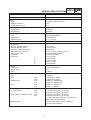

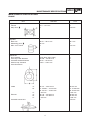

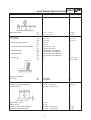


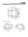

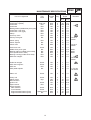
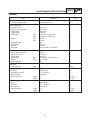


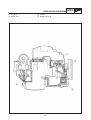


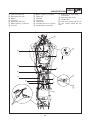


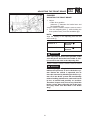

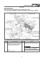


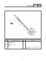
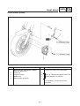

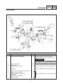


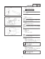
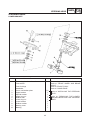


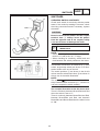
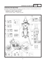


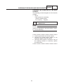


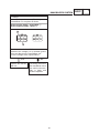


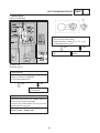


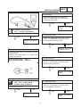
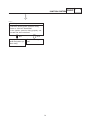


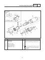


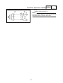


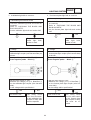

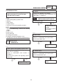

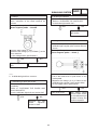
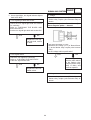
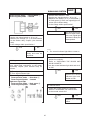


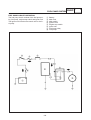


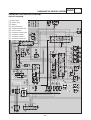


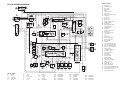


![Manuale Officina [ ITA ] Yamaha R1 2002-2003](http://vs1.manualzilla.com/store/data/006110674_1-52d32bbc9127defc0419b49b1226ec2b-150x150.png)