1
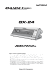
LPX-250
USER'S MANUAL
Thank you very much for purchasing the LPX-250.
•
To ensure correct and safe usage with a full understanding of
this product's performance, please be sure to read through this
manual completely and store it in a safe location.
•
Unauthorized copying or transferral, in whole or in part, of this
manual is prohibited.
•
The contents of this operation manual and the specifications of
this product are subject to change without notice.
•
The operation manual and the product have been prepared and
tested as much as possible. If you find any misprint or error,
please inform us.
•
Roland DG Corp. assumes no responsibility for any direct or
indirect loss or damage which may occur through use of this
product, regardless of any failure to perform on the part of this
product.
•
Roland DG Corp. assumes no responsibility for any direct or
indirect loss or damage which may occur with respect to any
article made using this product.
For the USA
FEDERAL COMMUNICATIONS COMMISSION
RADIO FREQUENCY INTERFERENCE
STATEMENT
This equipment has been tested and found to comply with the
limits for a Class A digital device, pursuant to Part 15 of the
FCC Rules.
These limits are designed to provide reasonable protection
against harmful interference when the equipment is operated
in a commercial environment.
This equipment generates, uses, and can radiate radio
frequency energy and, if not installed and used in accordance
with the instruction manual, may cause harmful interference
to radio communications.
Operation of this equipment in a residential area is likely to
cause harmful interference in which case the user will be
required to correct the interference at his own expense.
Unauthorized changes or modification to this system can void
the users authority to operate this equipment.
The I/O cables between this equipment and the computing
device must be shielded.
For Canada
CLASS A
NOTICE
This Class A digital apparatus meets all requirements of the
Canadian Interference-Causing Equipment Regulations.
CLASSE A
AVIS
Cet appareil numérique de la classe A respecte toutes les
exigences du Règlement sur le matériel brouilleur du
Canada.
ROLAND DG CORPORATION
1-6-4 Shinmiyakoda, Hamamatsu-shi, Shizuoka-ken, JAPAN 431-2103
MODEL NAME
: See the MODEL given on the rating plate.
RELEVANT DIRECTIVE : EC LOW VOLTAGE DIRECTIVE (73/23/EEC)
EC ELECTROMAGNETIC COMPATIBILITY DIRECTIVE (89/336/EEC)
This system (including the housing and safety device) is a Class 1 laser product. However, the laser light emitted internally is Class 2.
Laser specifications of this system (including the housing)
Wavelength: 600 to 700 nm, maximum output: 0.39 µW, pulse width 350 µs, pulse frequency: 2,875 Hz
This product complied with 21 CFR Chapter I Subchapter J
Complied with IEC Publication 60825-1, Amendment 1, 1997
CAUTION
Use of controls or adjustments or performance of procedures other than those specified herein may result in radiation exposure.
To Ensure Safe Use
To Ensure Safe Use
Please read this document completely before operating the machine. It contains safety cautions and information essential in assuring safe operation.
Observe all cautions in operation.
Cautions related to the safe operation of this machine are indicated as shown below.
About
and
Notices
Used for instructions intended to alert the user to the risk of death or severe injury
should the unit be used improperly.
Used for instructions intended to alert the user to the risk of injury or material
damage should the unit be used improperly.
* Material damage refers to damage or other adverse effects caused with respect to
the home and all its furnishings, as well to domestic animals or pets.
About the Symbols
The
symbol alerts the user to items that must never be carried out (are forbidden). The
specific thing that must not be done is indicated by the design contained within the circle. The
symbol at left means the unit must never be disassembled.
The
symbol alerts the user to things that must be carried out. The specific thing that must be
done is indicated by the design contained within the circle. The symbol at left means the powercord plug must be unplugged from the outlet.
The following symbols are also used.
: Indicates information to prevent machine breakdown or malfunction and ensure correct use.
: Indicates a handy tip or advice regarding use.
i
To Ensure Safe Use
Do not disassemble, repair, or modify.
Doing so may lead to fire or abnormal operation
resulting in injury.
Class 2 laser light may be emitted outside the
machine. Staring directly into the laser beam for
an excessive length of time may result in eye
injury.
Do not use with any electrical power
supply that does not meet the ratings
displayed on the AC adapter.
Use with any other power supply may lead to fire
or electrocution.
Do not use while in an abnormal state (i.e.,
emitting smoke, burning odor, unusual
noise, or the like).
Doing so may result in fire or electrical shock.
Immediately unplug the power-cord plug from the
electrical outlet, and contact your authorized
Roland DG Corp. dealer or service center.
Use only with the power cord included
with this product.
Use with other than the included power cord may
lead to fire or electrocution.
Do not use with any power supply other
than the dedicated AC adapter.
Use with any other power supply may lead to fire
or electrocution.
Do not use with a damaged AC adapter,
power cord, or power-cord plug or with a
loose electrical outlet.
Use with any other power
supply may lead to fire or
electrocution.
Doing so may damage
the electrical power cord,
leading to electrocution
or fire.
When not in use for several hours, unplug
the power-cord plug from the electrical
outlet.
When unplugging the electrical power
cord from the power outlet, grasp the plug,
not the cord.
Failure to do so may result in danger of shock,
electrocution, or fire due
to deterioration of the
electrical insulation.
Unplugging by pulling the cord may
damage it, leading
to fire or electrocution.
Do not attempt to unplug the power-cord
plug with wet
hands.
Install on a stable surface.
Doing so may result
in electrical shock.
ii
Do not injure or modify the electrical
power cord, nor subject it to excessive
bends, twists, pulls, binding, or pinching,
nor place any object
of weight on it.
Failure to do so may result in falling of the unit,
leading to injury.
To Ensure Safe Use
Do not insert metal objects, flammable
objects, or any other foreign object into
interior areas other than the top of the
table. Also, do not place water or other
liquids on any area, including the table.
Do not use if the housing or window area is
cracked or deformed.
In such cases, there is danger of external emission
of Class 2 laser light. Staring at externally emitted
laser light may cause eye injury.
Doing so may cause fire.
Lifting and carrying are operations that
must be carried out by two persons, by
grasping the bottom of the machine.
Securely fasten the object to be scanned
to the table so that it does not slip or topple
over.
Failing to do so may result in injury.
The table rotates during scanning. Tipover or
contact by the scan object may cause damage.
Scan-object damage is not covered by warranty.
Do not attempt to scan objects that are
highly reflective or refractive, such as
mirrors, prisms, or lenses.
In such cases, there is danger of external emission
of Class 2 laser light. Staring at externally emitted
laser light may cause eye injury.
Important Cautions Regarding Laser Light
This machine uses a laser beam to scan objects, but dangerous laser radiation is not emitted outside the machine. It is safe to view the laser light
through the window.
However, this may not be the case if the machine is disassembled or if its cover or safety devices are broken or disabled. Please observe the
cautionary notes in this documentation and never attempt to use this machine if the machine is in an abnormal state.
The natural blink reflex protects the eye in the event that laser light from the machine directly enters the eye due to incorrect use or the like, but
staring directly into the laser beam may result in eye injury. Direct contact with the laser beam will not cause burns or fire.
Items That may Not Be Copied
Unauthorized reproduction of a copyrighted item for any purpose other than personal use may be a violation of copyright. Roland DG Corp.
will not be responsible for any violation of third-party copyright by any article made through use of this product.
iii
To Ensure Safe Use
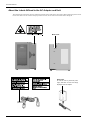
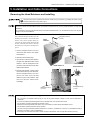
About the Labels Affixed to the AC Adapter and Unit
This machine bears caution labels. These are intended to ensure the safety of the operator. They must be affixed at the appropriate locations.
Do not allow them to become soiled or attempt to peel them off. Also, be sure to observe the stated cautions during use.
Model name
Rating label
Do not use with any electrical power
supply that does not meet the ratings
displayed on the AC adapter.
iv
Table of Contents
Table of Contents
Part 1 Startup
2. Scanning Operation .............................................................. 18
1. Checking the Accessories ..................................................... 1
3. Viewing the Results of Scanning ....................................... 19
2. Three Manuals for Using the LPX-250 ................................. 2
Manipulating the Perspective and the Zoom Rate ..................... 19
3. LPX-250 System Configuration ............................................ 3
Changing the Display Method .................................................. 19
4. Names and Functions ............................................................. 4
4. Creating a Polygon Mesh ..................................................... 20
5. Installation and Cable Connections .................................... 5
5. Saving the Results of Scanning ......................................... 21
Removing the Head Retainers and Installing .............................. 5
Saving the Results of Scanning ................................................. 21
Connect the Cable ....................................................................... 6
Exporting Data ......................................................................... 21
6. Switching the Power On and Off
and Opening and Closing the Door .............. 8
Part 4
Features for Better Scanning
Steps for Switching On the Power .............................................. 8
1. Detailed Settings for Plane Scanning ............................... 22
Switching Off the Power ............................................................. 8
Scanning Using Manual Settings .............................................. 22
Opening and Closing the Door ................................................... 8
Detailed Scanning Conditions ................................................... 23
7. Preparing the Programs ......................................................... 9
2. Detailed Settings for Rotary Scanning .............................. 24
Programs Installed and Set Up .................................................... 9
Scanning Using Manual Settings .............................................. 24
System Requirements ................................................................. 9
Detailed Scanning Conditions ................................................... 25
Steps for Installing and Setting Up the Programs ...................... 10
3. Finishing Detailed Areas Using Rescanning ................... 26
Starting Dr. PICZA3 ................................................................. 10
Finishing Areas That Could Not Be Scanned ............................ 26
Selecting the Communication Port ............................................ 10
Scanning a Specific Area in Greater Detail ............................... 28
4. Case Studies for Better Scanning ...................................... 29
Part 2
Basics of the LPX-250
Scanning Results for Objects That Are Difficult to Scan ........... 29
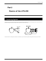
1. Scanning System ................................................................... 11
Choosing the Scanning Mode ................................................... 29
2. Suitable and Unsuitable Objects for Scanning ............... 12
The Scanning-start Direction for Plane Scanning ...................... 31
3. Plane Scanning ...................................................................... 13
Object Mounting Location for Rotary Scanning ....................... 31
Features of Plane Scanning ....................................................... 13
Mounting Orientation for the Scan Object ................................ 13
Part 5 Editing Scanning Results -- Using 3D Editor
4. Rotary Scanning ..................................................................... 14
1. What You Can Do Using 3D Editor ..................................... 32
Features of Rotary Scanning ..................................................... 14
2. Importing and Exporting Data ............................................. 32
Finishing by Rescanning ........................................................... 14
Importing Scanning Results Immediately ................................. 32
5. Mounted Position of the Object
Importing More Than One Set of Data ..................................... 32
and the Scannable Area ................................. 15
Exporting Data in Other Formats .............................................. 32
Plane Scanning ......................................................................... 15
3. Basic Operations for Objects .............................................. 34
Rotary Scanning ....................................................................... 16
How to View the 3D Editor Window ........................................ 34
Effective Sensor Area ............................................................... 16
Let's Try Editing Data with 3D Editor ...................................... 35
Part 3
Basic Operation
Part 6
Troubleshooting ................................................... 37
1. Getting Ready to Scan .......................................................... 17
Selecting a Scan Object ............................................................ 17
Part 7 Appendix
Deciding on the Scanning Mode ............................................... 17
1. Sample Data Sheet ................................................................ 39
Mounting the Scan Object ........................................................ 17
2. Table Dimensional Drawing ................................................. 40
3. Specifications ......................................................................... 41
Windows® and Windows NT® are registered trademarks or trademarks of Microsoft® Corporation in the United States and/or other countries.
Adobe and Acrobat are trademark of Adobe Systems Incorporated.
Pentium is registered trademark of Intel Corporation in the United States.
IBM is trademark of International Business Machines Corporation.
Other company names and product names are trademarks or registered trademarks of their respective holders.
Copyright © 2001 Roland DG Corporation
http://www.rolanddg.com/
1. Checking the Accessories
Part 1
Startup
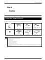
1. Checking the Accessories
The following included items are packed with the LPX-250. Check first to make sure that all items are present.
AC adapter : 1
Power cord : 1
Hexagonal wrench
(size : 2.5 mm) : 1
Hexagonal wrench
(size : 3 mm) : 1
Caps : 3
CD-ROM
(Roland Software Package) : 1
User’s Manual : 1
Roland Pixform™ : 1
The Contents of the CD-ROM
The included CD-ROM contains the following items.
• Dr. PICZA3 program
• 3D Editor program
• Dr. PICZA3 User's Manual (PDF)
• 3D Editor User's Manual (PDF)
• Adobe Acrobat Reader ver. 4 program
Also included are programs and documentation for MODELA series modeling machines from Roland DG Corp., but they are not for use with
the LPX-250.
1
Part 1 Startup
2. Three Manuals for Using the LPX-250
Three manuals are included with this machine.
LPX-250 User's Manual
(this manual)
Read this first. This describes important notes, setup, operation, troubleshooting, and other matters
related to using the LPX-250.
Dr. PICZA3 User's Manual
(electronic-format manual)
Refer to these as required. They describe in detail all the functions of the included Dr. PICZA3 and
3D Editor programs.
These manuals are in electronic (PDF) format, and printed versions are not included. They are found
on the included "Roland Software Package" CD-ROM. You can easily view them or even print them
out by following the steps below. You can also view the same information from the online help for
each program.
3D Editor User's Manual
(electronic-format manual)
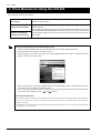
Viewing the Included Electronic Documentation (PDF Format)
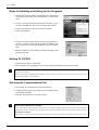
1. Insert the included CD-ROM into the computer's CD-ROM drive. A menu window appears automatically.
2. Click the place that says "Click here," then select "LPX-250."
3. Click the [?] button to the right of the program name. Acrobat Reader starts and the window for choosing the manual
appears. Click the item you want to view.
4. When you are viewing for the first time, installation and setup of Acrobat Reader may start. If this happens, follow the onscreen instructions to proceed with installation and setup.
5. You can go on to the next page or go back to the previous page by pressing the left and right arrow keys on the keyboard.
(You can also do this using the on-screen [
] and [
] buttons.)
About Adobe Acrobat Reader
Acrobat Reader is a program required to view files in PDF format. Acrobat Reader is found on the included CD-ROM. If Acrobat Reader is
not set up on the computer you're using, then it is installed automatically to enable you to view the manual easily, no matter what kind of
computer you're using.
* Acrobat Reader is a product of Adobe Systems Incorporated. For detailed information on how to use it, go to the Acrobat Reader menu and
select [Help] to view the online help.
2
2. Three Manuals for Using the LPX-250 3. LPX-250 System Configuration
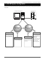
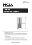
3. LPX-250 System Configuration
The LPX-250 system is made up of the 3D scanner unit, a computer running Windows (available separately), a scanning program, and a program for
editing 3D data.
3D scanner unit
Computer running Windows
Scanning program
3D-data editing program
Dr. PICZA3
3D Editor
Exporting data
Exporting data
PIX format
DXF format (3D surfaces)
DXF format (3D surfaces)
STL format (text/binary)
STL format (text/binary)
Importing data
Point group data format
Saving and reading data
DXF format (3D surfaces)
Dr.PICZA Project format
STL format (text/binary)
PIX format (reading only)
Dr.PICZA Project format
PIX format
IGES format (surfaces)
VRML format
3DMF format
Point group data format
LightWave 3D format
3D Studio format
Wavefront Obj format
3
Part 1 Startup
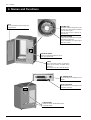
4. Names and Functions
Door
Be sure to keep this closed during scanning operations.
Standby key
This button switches the power on and
off. When on, it lights up green. It flashes
when the door is open.
When an error occurs, it lights up orange and red.
Movement LEDs
During scanning operations, the green
lights flash one at a time.
During initialization, the green lights
flash two at a time.
Interlock switch
This is one of the safety devices. Do not
insert any objects here.
Table
This is the base on which you place the
object to be scanned. It rotates during
scanning.
Do not touch any other internal devices.
AC adapter jack
This is the jack for connecting the AC
adapter.
Serial connector
This connector is for connection to the
computer's COM port.
Cable hooks
These are used to bundle and hold the
connected cables.
4
4. Names and Functions 5. Installation and Cable Connections
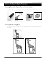
5. Installation and Cable Connections
Removing the Head Retainers and Installing
Lifting and carrying are operations that must be carried out by two persons, by grasping the bottom of the
machine. Failing to do so may result in injury.
Be sure to remove the head retainers before use. Failure to remove them may not only impede operation, but may cause
breakdown.
Do not attempt to touch any internal area other than the items described below, or to use excessive force to move any item.
Doing so may result in breakdown.
After you take the machine out of the carton, the
first thing you need to do is to remove the head
retainers. Carry out this operation before you
connect the AC adapter. When transporting the
machine, reattach the head retainers. Store the
head retainers in a safe place so that they do not
get lost.
Hexagonal wrench
(3 mm)
Head
retainer 1
Caps
1. Use the hexagonal wrench (3 mm) to
remove the three screws, then detach
head retainer 1.
2. Attach the three included caps.
3. Open the door. The blue panel visible to
the right of the table at the back is head
retainer 2. Use the hexagonal wrench
(2.5 mm) to remove the five screws, then
Head retainer 2
detach head retainer 2.
Head retainer 3
4. Remove head retainer 3, which is blue
and located at the top of the head unit.
Use the hexagonal wrench (3 mm) to
remove one screw, then pull head
retainer 3 up and out to extract it. Take
care not to drop the retainer when
extracting it.
Hexagonal wrench
(2.5 mm)
Hexagonal wrench
(3 mm)
When installing, be careful of the following points.
• Do not install in an unstable location. Doing so may not only lead to danger of falling, but may result in breakdown or
malfunction.
• Avoid use in locations exposed to large amounts of electrical noise, such as areas near motors.
• Do not install in a location exposed to high humidity or dust.
• Because the machine generates heat when in use, do not install in a location where heat radiation is poor.
• Do not install in locations exposed to severe vibration.
• Use in an environment where temperature is between 10 ˚C and 40 ˚C (between 50 ˚F and 104 ˚F) and relative humidity is
between 35 % and 85 % (with no condensation).
• Avoid using in an environment exposed to severe changes in temperature. Such use may affect scanning accuracy.
5
Part 1 Startup
Connect the Cable
Do not use with any power supply other than the dedicated AC adapter.
Use with any other power supply may lead to fire or electrocution.
Do not use with any electrical power supply that does not meet the ratings displayed on the AC adapter.
Use with any other power supply may lead to fire or electrocution.
Use only with the power cord included with this product.
Use with other than the included power cord may lead to fire or electrocution.
Do not injure or modify the electrical power cord, nor subject it to excessive bends, twists, pulls, binding, or
pinching, nor place any object of weight on it.
Doing so may damage the electrical power cord, leading to electrocution or fire.
Do not attempt to unplug the power-cord plug with wet hands.
Doing so may result in electrical shock.
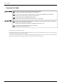
Connect the power cord and the AC adapter.
Also make the connection to the computer's COM port (RS-232C port, serial port). The computer may have two or more COM ports, so
make sure of the number of the connected COM port.
Use a serial cable from Roland DG Corp. sold separately (for an IBM-compatible computer, use a crossover cable such as the XY-RS-34).
Straight-wired cables like those used mainly for modem connections cannot be used for operation.
6
5. Installation and Cable Connections
Back of the scanner
Serial connector
AC adapter jack
Serial cable
(crossover cable such as the XY-RS-34.
Refer to Part 7 and see “3. Specifications”.)
AC adapter
COM2
Power cord
COM1
Computer COM ports
After you make the connections,
secure the cables.
Connect the AC adapter and power cord securely so that they do not come loose or experience faulty connection. Failure to do
so may result in breakdown or malfunction.
Switch off the power to the computer and the machine before you make the cable connections.
Be sure to make the connection to a COM port. Connection to an incorrect port such as a printer port, may not only result in the
system failing to operate, but may lead to breakdown.
7
Part 1 Startup
6. Switching the Power On and Off and Opening and Closing the Door
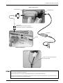
Steps for Switching On the Power
There is a proper procedure for switching on the power to the machine. Follow the steps
Movement LEDs
below.
1. Close the door.
2. Press the Standby key.
3. The Movement LEDs flash. Keep the door closed until the flashing stops.
During this interval, the machine is performing initialization.
4. When initialization ends, the Standby key lights up green and the Move-
Standby key
ment LEDs go dark. Scanning is now possible.
Initialization may take up to about 40 seconds. If the door is opened during initialization, operation is interrupted to ensure safety.
In such cases, correct scanning cannot be performed. Switch off the power, close the door, then switch the power on again. Also,
sound that is differ from what you usually hear may be heard for several seconds during initialization, but this does not indicate
a malfunction.
Starting the computer after switching on the machine may make it impossible to perform scanning. This may occur depending
on the computer, but does not indicate a malfunction. If this happens, start the computer first, and then switch on the power to the
machine. Also, if the computer is restarted, reset the power to the machine as well.
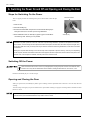
Switching Off the Power
When the machine will not be in use for a prolonged period, unplug the power cord from the electrical outlet.
Failure to do so may result in deterioration of the insulation, leading to electrical shock, short circuit, or fire.
Hold down the Standby key for 1 second or longer.
Opening and Closing the Door
When you open the door, the Standby key flashes green. Scanning cannot be performed while in this state. Close the door, then start
scanning.
To ensure safety, an emergency stop occurs when the door is opened while scanning is in progress. Scanning cannot be resumed even after
the door is closed.
If the Standby key does not flash when you open the door, the safety device may have failed. If this happens, immediately stop
use and contact your authorized Roland DG Corp. dealer or service center.
8
6. Switching the Power On and Off and Opening and Closing the Door 7. Preparing the Programs
7. Preparing the Programs
Programs Installed and Set Up
Dr. PICZA3 and 3D Editor are both installed and set up.
System Requirements
The computer's system requirements for Dr. PICZA3 and 3D Editor are as follows.
Operating system
Windows 95, Windows 98, Windows Me, Windows NT 4.0, Windows 2000, and Windows XP
Processor
Pentium II or higher recommended
Memory (RAM)
128 MB or more recommended
Free hard-disk space
for installation
10 MB (for both Dr. PICZA3 and 3D Editor)
Monitor
640 x 480 resolution, 256 colors or higher
(800 x 600 resolution or higher, 16-bit color (High Color) or higher, and OpenGL-compatible
or more recommended)
Interface
COM port (Serial port)
* Memory requirement are affected by scanning conditions and the like. Larger scanning areas and finer scanning pitches require increasingly more memory. We recommend installing enough memory to match your usage conditions.
9
Part 1 Startup
Steps for Installing and Setting Up the Programs
1. Start Windows. If you are installing under Windows NT 4.0/2000/XP, log
on to Windows as a member of the "Administrators" or "Power Users"
group.
2. Insert the included CD-ROM (Roland Software Package) into the
computer's CD-ROM drive. The setup menu appears automatically.
3. Click the place that says "Click here," then select "LPX-250."
4. Click the [Install] button.
5. Follow the on-screen setup instructions, clicking the [Next] button to
proceed. If you want to specify a particular folder for installation, do it
here. In most cases you can simply click [Next] to proceed. Installation
starts.
6. When all installation and setup finishes, the final window appear. Click
[Close] to finish setup.
Starting Dr. PICZA3
1. First switch on the power to the LPX-250.
2. Next, in Windows, click the [Start] button, then click [Programs], then [Roland PICZA], then [Dr. PICZA3].
When Dr. PICZA3 starts, it attempts to verify the name of the model of the 3D scanner that is connected. Be sure to turn on the LPX-250
before you run Dr. PICZA3.
With this system, the [Run MODELA Player] and [Run 3D Engrave] buttons in Dr. PICZA3 are not used. Use them when you are using
together with the MODELA series or the like.
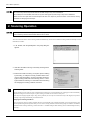
Selecting the Communication Port
1. In Dr. PICZA3, go to the [File] menu and click [Preferences].
2. For [Port], select the number of the COM port on the computer to which
the LPX-250 is connected.
3. Click [OK]. The LPX-250 can now perform scanning.
Special Notes for Windows NT 4.0/2000/XP
Care is required when another printer driver or the like is set to use a COM port. Scanning cannot be performed when the same COM port is
selected for the other driver and Dr. PICZA3. Take action such as connecting to a different COM port to avoid conflicts with the other driver.
Checking the Connection
In Dr. PICZA3, go to the [Help] menu and display [About]. If the firmware version and model name are displayed, the connection is correct.
10
1. Scanning System
Part 2
Basics of the LPX-250
1. Scanning System
The LPX-250 scans objects using laser light. It emits a spot beam onto the scan object and detects reflected light from the object with sensors. It
performs scanning as it rotates the scan object and moves the laser beam from bottom to top.
Laser emitter
Sensor
Rotating table
The LPX-250 has two scanning modes. Each has its own features, so you can choose the optimal scanning mode for the object to be scanned.
11
Part 2 Basics of the LPX-250
2. Suitable and Unsuitable Objects for Scanning
The LPX-250 cannot scan every single kind of object. Adequate thought must be given to the material of an object, because it greatly affects the
scanning results.
Yes
Objects that do not pass light
Yes
Relatively smooth-surfaced objects
No
Clear or transparent objects
No
Fabric or fuzzy objects
* Applying white surfacer (primer) may produce better results.
Yes
Brightly colored objects (white, yellow, red, etc.)
Yes
Objects of a nonglossy material such as plaster,
wood, or modeling clay
No
Dark-colored objects (black, blue, green, etc.)
No
Glossy and highly reflective objects (metals, mirrors,
etc.)
* Applying white surfacer (primer) may produce better results.
No
* Applying white surfacer (primer) may produce better results.
* Avoid highly reflective objects because of danger of eye injury.
Areas where the angle of the laser beam is too shallow
In many cases it is not possible to
scan areas near the top of an object.
20 degrees or less
12
2. Suitable and Unsuitable Objects for Scanning
3. Plane Scanning
3. Plane Scanning
Features of Plane Scanning
This mode uses parallel laser beams to scan while rotating the table and laser head in synchronization. Because this mode can obtain
comparatively stable scanning results regardless of the shape of the object, you can use it as an all-purpose mode. You can use it to scan up
to six surfaces at one time (multi-plane composition).
The laser beams strike
substantially in parallel.
Multi-plane composition
(four scanning surfaces)
Plane scanning system
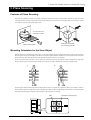
Mounting Orientation for the Scan Object
When the object to be scanned has areas with cavities or voids, plane scanning, which uses parallel laser beams, is effective. This is because
the laser light can easily pass through the voids. However, if the laser light is blocked by another area, it becomes impossible to determine
that the void exists. This means the direction from which the laser light is beamed is very important.
If you are scanning a doll, for instance, you can capture the voids between the legs and under the arms by aiming the laser light in the
direction shown in figure A. If the orientation in figure B is used, the laser light is blocked and so the two legs end up joined.
B
A
The laser light is emitted from the right side. This means that if your aim is to capture the void between the legs, for example, it is best to
mount the doll so that it faces right. The direction in which the laser light is incident is decided by the orientation of the scan object mounted
on the table. With multi-plane composition, this orientation is the first surface for scanning.
Table
Orientation of the laser light
13
Part 2 Basics of the LPX-250
In general, increasing the number of scanning surfaces results in greater scanning precision with correspondingly fewer conspicuous seams.
In the example of the doll, however, only one of the five scanning surfaces can capture the voids. From the standpoint of capturing voids,
two surfaces are more effective.
Scanning surfaces: 5
Scanning surfaces: 2
4. Rotary Scanning
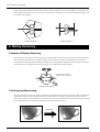
Features of Rotary Scanning
This mode scans the outer perimeter of the scan object while rotating the table in one direction. This is suited to scanning objects that have
relatively little unevenness and are close in shape to a sphere or cylinder, and lets you perform smooth scanning for curved surfaces.
It is more selective of the shape of the object than plane scanning, but conversely reproduces smooth curves even at relatively coarse pitches,
and also takes less time. Capturing cavities and voids in objects is more difficult than with plane scanning.
The laser beam is emitted
toward the center of the table.
Rotary scanning system
Finishing by Rescanning
If the object is highly uneven, there may be many areas that the laser light does not reach. Rotary scanning is more likely to be affected by
this than plane scanning, and may result patches that are not scanned. With rotary scanning, you can finish such areas by rescanning.
Perform rotary scanning for the entire object, then rescan only the areas you want to finish. This enables scanning with an attractive finish
even for detailed portions while smoothly reproducing the curved features of the entire object.
Rescanning
14
4. Rotary Scanning
5.
Mounted Position of the Object and the Scannable
Area
5. Mounted Position of the Object and the Scannable Area
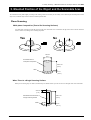
The scannable area may differ slightly according to the scanning mode. The area that you can actually scan is affected by the mounted position of the
object. Also, mount the object so that it does not extend beyond the table.
Plane Scanning
Multi-plane Composition (Two to Six Scanning Surfaces)
For multi-plane composition, mount the object near the center of the table. If it is mounted at the edge of the table it will fall outside the
effective sensor area, making correct scanning impossible.
No
Yes
230 mm
(9 in.)
Scannable area for
multi-plane composition
406.4 mm
(16 in.)
Table
3 mm
(1/8 in.)
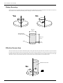
When There Is a Single Scanning Surface
When you are scanning only one surface, mount the object so that the surface you want to scan lies to the right of the center of the table.
230 mm
(9 in.)
Scannable area when there is
a single scanning surface
406.4 mm
(16 in.)
Table
3 mm
(1/8 in.)
15
Part 2 Basics of the LPX-250
Rotary Scanning
The basic principle is to mount the object to be scanned at the center of the table. All areas to be scanned must be at the table center. The area
away from the center of the base (the shaded portion in the figure) cannot be scanned correctly.
No
Yes
254 mm
(10 in.)
Scannable area
for rotary scanning
406.4 mm
(16 in.)
Table
3 mm
(1/8 in.)
Effective Sensor Area
The area where the laser sensor detects reflected laser light is to the right of the center of the table. This is the effective sensor area. When
laser light is reflected from the area to the left of the table center, the LPX-250 decides that there is no object to scan. The surface of an object
mounted at the table center always passes within the effective sensor area, and the laser light is always reflected from the area to the right.
This effective sensor area must also be taken into account when the object has large depressions or shelf-shaped areas.
Effective sensor area
No
16
1. Getting Ready to Scan
Part 3
Basic Operation
1. Getting Ready to Scan
Selecting a Scan Object
Before you start scanning, give thought to what objects are suited to scanning.
Conditions for suitable scanning
Remedies when unsuitable
Object material and
color
Does the objects not pass light?
Is the object a bright color such as white or yellow?
Is the object of a nonglossy material?
Consider applying a white surfacer (primer).
Object size
Does the object fit on the table?
Think about whether you can break down the object
into separate parts.
Object shape
Can the object be placed on the table in a stable way?
Does the object have many areas that laser light
cannot reach?
Consider using a fixing frame or clay to secure in place.
Think about whether you can break down the object
into separate parts.
Deciding on the Scanning Mode
Give thought to whether to perform scanning in the plane scan mode or the rotary scan mode. In general, it is a good idea to select rotary
scanning for objects that are nearly cylindrical and have relatively little unevenness, and plane scanning for other objects.
If an object is nearly cylindrical overall but has one or more areas that are not suited to rotary scanning (such as the handle of a coffee cup),
you may consider using rotary scanning to scan the entire object, then using rescan for finishing. For detailed information about rescanning,
go to Part 4 and refer to "3. Finishing Detailed Areas Using Rescanning."
Mounting the Scan Object
Do not insert metal objects, flammable objects, or any other foreign object into interior areas other than the top of
the table. Also, do not place water or other liquids on any area, including the table. Doing so may cause fire.
Securely fasten the object to be scanned to the table so that it does not slip or topple over. The table rotates
during scanning. Tipover or contact by the scan object may cause damage. Scan-object damage is not covered
by warranty.
Mount the scan object near the center of the table. For Rotary scanning in particular, mounting the object away from the center may make
it difficult to obtain good scanning results.
The table rotates during scanning, so secure the object in place using double-sided tape, clay, or an optionally available vise to keep the
object from falling over or slipping.
17
Part 3 Basic Operation
Do not touch any internal components other than the table. Doing so may result in breakdown.
Do not attempt to move the table, laser head, or any other working parts by hand. Doing so may result in breakdown.
Make sure the scan object does not extend beyond the table. The object may touch the interior of the machine, causing
breakdown or damaging the scan object.
2. Scanning Operation
Do not open the door while scanning operations are in progress. To ensure safety, an emergency stop of scanning operations
occurs. Scanning cannot be resumed even after the door is closed.
This section describes how to set the scanning conditions automatically. You can also set detailed scanning conditions manually. For more
information, see Part 4.
1. In Dr. PICZA3, click the [SCAN] button. The [Scan] dialog box
appears.
2. Click either the Plane Scanning or the Rotary Scanning button.
Scanning starts.
3. Examine the results of scanning. As required, perform finishing
by rescanning, or modify the scanning conditions and do scanning over from the beginning. For more information about viewing the scanning results, refer to the following section, "3. Viewing the Results of Scanning." For information about rescanning
and changing the scanning conditions, see Part 4.
Automatic Setting of Scanning Conditions
In this operation, the size of the scan object is detected and the scanning area is set automatically. The scanning pitch is also automatically
adjusted according to the size of the object. For plane scanning, the number of scan surfaces is always four.
If the object has a highly irregular shape or long, narrow protrusions, the size may not be detected correctly. If this happens, then perform
scanning using settings made manually, as described in Part 4.
Verifying the Scanning Conditions
You can check and verify the scanning conditions that were set automatically. After scanning has finished, go to the [Scan] dialog box and
click the [Make Settings and Scan] button. Here you can revise the scanning conditions and redo scanning using new conditions. For detailed
information about scanning conditions, go to Part 4 and refer to "1. Detailed Settings for Plane Scanning" and "2. Detailed Settings for Rotary
Scanning."
18
2. Scanning Operation 3. Viewing the Results of Scanning
3. Viewing the Results of Scanning
You can check the scanning results while viewing the results in various ways.
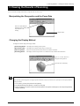
Manipulating the Perspective and the Zoom Rate
Click one of these buttons to
enable the mode for shifting
the perspective or for
zooming.
Drag the object.
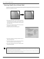
Changing the Display Method
Clicking these buttons changes the display method.
[Point Group] button This displays the scanning points as points.
[Wire Frame] button
This displays the scanning results using wire-frame lines.
[Hide Lines] button
This uses wire-frame lines but does not show areas that are in shadow.
[Rendering] button
This displays surfaces and provides a view that most closely resembles the actual article.
Click one of these buttons to
change the viewing method.
View when set to "Rendering"
Speeding Up Screen Display
If the operating system and graphics card support OpenGL and the like, it may be possible for you to speed up the screen display. Make the
settings as follows.
1. In Dr. PICZA3, go to the [View] menu and click [Options].
2. For [Drawing Method], select OpenGL or the like, then click [OK].
3. If the screen display is corrupted, it means the selected method is not supported. If that happens, return the [Drawing Method]
setting to [Software].
19
Part 3 Basic Operation
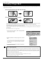
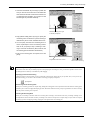
4. Creating a Polygon Mesh
Depending on the conditions, the scanning results may be as shown below. Creating a polygon mesh allows you to produce finished data closer to the
original image of the scan object.
Areas joined because the laser light does not reach
Areas with holes due to surface drop-out
A polygon mesh is composed of polygons created by estimating the original shape of the scan object from the scanning points. They differ
from the polygons displayed immediately after scanning, which are generated simply by connecting the scanning points.
A polygon mesh can be generated from data measured by either a plane scan or a rotary scan. A single set of polygon-mesh data is generated
even from Multiple-plane scanning data, such as multi-plane composition.
Creating a polygon mesh enables you to make cavities in areas where there are no scanning points and to fill in holes according to the
surrounding shape.
This section describes how to create a polygon mesh.
1. Click the [Create Polygon Mesh...] button. The [Polygonization
Options] dialog box appears.
[Create Polygon Mesh...]
button
2. Select the parameters for creating a polygon mesh, then click
[OK].
For more information about the [Polygonization Options] dialog
box, please refer to the “Dr. PICZA User’s Manual” (electronicformat manual).
3. If the polygon mesh is not what was intended, change the parameters and create it again.
Tips for Creating a Polygon Mesh
Creating a polygon mesh generates polygons only in areas where there is a high density of scanning point. Using data with a large number of
scanning points can raise the degree of completeness of the polygon-mesh data. To increase the number of scanning points, you use a finer
scanning pitch. Note that this also increases both the scanning time and the amount of memory required. If not enough memory is available,
or if you want to shorten the scanning time, it may be helpful first to perform scanning at a coarse pitch, then rescan just the necessary areas
at a fine pitch, and then generate the polygon mesh.
Rescanning may also be effective in situations like the following.
- When there are areas that have few scanning points with respect to the undulations on the scan object
- When areas with holes are too big or the shape of them is complex
For more information about rescanning, see Part 4.
20
4. Creating a Polygon Mesh 5. Saving the Results of Scanning
5. Saving the Results of Scanning
Saving the Results of Scanning
To save the results of scanning, then in Dr. PICZA3, go to the [File] menu and click [Save As].
The data is saved in Dr. PICZA project format (with the file extension .pij). A single file saved in this format contains both the scanning data
and the polygon-mesh data. If no polygon mesh has been generated, then only the scanning data is saved.
In addition to Dr. PICZA3, the 3D Editor program for editing 3D data can also open files in this format.
Exporting Data
Using the [Export] command allows you to make use of scanning results with another program. You choose and export either the scanning
data or the polygon-mesh data. You can save (export) scanning results in PIX format (text or binary), DXF format (3D surfaces), STL
format (text or binary), or Point Group format.
1. Display the data you want to export. From the [View] menu, choose either [Scanning Data] or [Polygon Mesh].
2. In Dr. PICZA3, click the [Export] button. Click the file format you want to use for exporting.
3. For PIX format and STL format, select either text or binary, then click [OK]. For Point Group format, select the separator
character, then click [OK]. Select one supported by the program with which you want to share the data.
[Export] button
PIX format and STL format
Point Group format
4. Type in the name of the file to export, then click [Save].
Scanning Data and Polygon-mesh Data
Scanning data is data for measuring points (scanning points) obtained by scanning.
Polygon-mesh data is data composed of new polygons created by estimating the proper shape of the scan object from the scanning data.
When exporting data, take into account the differences just described and choose the appropriate data for the purpose.
When raw measurement data is needed, export the scanning data. When polygon data for creating three-dimensional computer graphics is
needed, it may be best to export the polygon-mesh data.
21
Part 4 Features for Better Scanning
Part 4
Features for Better Scanning
1. Detailed Settings for Plane Scanning
In addition to the automatic scanning-condition settings, you can also make the settings manually, to any values you like.
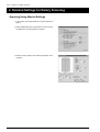
Scanning Using Manual Settings
1. In Dr. PICZA3, click the [SCAN] button. The [Scan] dialog box
appears.
2. Click the [Make Settings and Scan] button for plane scanning.
The [Settings for Scanning] dialog box appears.
3. Set the scanning conditions, then click the [Scan] button. Scanning starts.
22
1. Detailed Settings for Plane Scanning
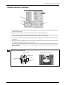
Detailed Scanning Conditions
(1)
(5)
(3)
(2)
(6)
(4)
(1) This sets the number of scanning surfaces. For multi-plane composition, select a number from [2] to [6]. The preview
window shows the scanning surfaces.
(2) This manipulates the orientation that the preview window displays. You can do things like rotating the preview or displaying
a three-dimensional view.
(3) Click this to display a preview of the object. Use this as a guide for setting the scanning area.
(4) These set the height-direction and width-direction scanning pitch.
(5) This sets the scanning area. You can make the setting for [Offset Amount] only when the number of surfaces to scan is
set to [1].
(6) Clicking this button displays estimates of the amount of memory required for scanning and the scanning time. Whenever
you change the scanning conditions, click this button again.
Performing scanning that exceeds the amount of free memory of the computer may greatly reduce performance for such
tasks as updating the screen display. We recommend installing sufficient memory in the computer when you are performing
large-size scanning.
The Important Point Is to Use the Minimum Required Scanning Area
The smaller the scanning area is, the sooner scanning finishes. You can
achieve efficient scanning by making the setting for the minimum area that
is required. If you don't actively set the scanning area, the entire scannable
area is scanned.
Tips for Setting the Scanning Pitch
This settings determines the extent to which detailed portions are reproduced. Smaller (finer) pitches do not make for correspondingly greater
smoothness. When extreme detail is not necessary, it can actually be more
effective to set a coarse pitch.
Width-direction pitch
Last
point
Heightdirection
pitch
Scanning
height
Start
point
Units Used by Dr. PICZA3
Dr. PICZA3 can display values in either millimeters or inches. The default
setting is determined by the setting for the measurement system in Windows. To change the unit, follow the steps below.
Scanning
width
1. In Dr. PICZA3, go to the [File] menu and click [Preferences].
2. Set [Units] to either [mm] or [inch].
3. Click [OK].
23
Part 4 Features for Better Scanning
2. Detailed Settings for Rotary Scanning
Scanning Using Manual Settings
1. In Dr. PICZA3, click the [SCAN] button. The [Scan] dialog box
appears.
2. Click the [Make Settings and Scan] button for rotary scanning.
The [Settings for Scanning] dialog box appears.
3. Set the scanning conditions, then click the [Scan] button. Scanning starts.
24
2. Detailed Settings for Rotary Scanning
Detailed Scanning Conditions
(4)
(2)
(1)
(5)
(3)
(1) This manipulates the orientation that the preview window displays. You can do things like rotating the preview or displaying
a three-dimensional view.
(2) Click this to display a preview of the object. Use this as a guide for setting the scanning area.
(3) These set the circumferential and height-direction scanning pitch. For the unit of measurement for circumferential pitch,
you can select either degrees or the number of segments of the circumference (360 degrees).
(4) This sets the scanning area. Setting [Circumferential] to either [0] or [360] results in scanning of the entire 360-degree
circumference.
(5) Clicking this button displays estimates of the amount of memory required for scanning and the scanning time. Whenever
you change the scanning conditions, click this button again.
Performing scanning that exceeds the amount of free memory of the computer may greatly reduce performance for such
tasks as updating the screen display. We recommend installing sufficient memory in the computer when you are performing
large-size scanning.
Scanning Area and Scanning Pitch
Circumferential pitch
Oriented 0 degrees circumferentially
0 degrees
circumferentially
Height-direction
pitch
Last point
Scanning height
Start point
25
Part 4 Features for Better Scanning
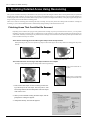
3. Finishing Detailed Areas Using Rescanning
After you have scanned an entire object, this feature rescans just one portion with changed conditions. Basic scanning should always be performed
using the best possible conditions, of course, but by using rescan to finish detailed portions you can make the data even more highly finished. If a
created polygon mesh is not what you intended, then it may be possible to generate more highly finished data by creating the polygon mesh again after
using rescanning to increase the number of scanning points.
There are two modes of rescanning: plane rescanning and rotary rescanning. You may freely choose the scanning mode for both basic scanning and
rescanning, so you can also use different modes in combination by taking advantage of the characteristics of each.
Finishing Areas That Could Not Be Scanned
Depending on the conditions, the polygon mesh generated after scanning may end up as described below. However, you can perform
finishing by using plane rescanning. This is a feature that lets you do scanning over again in the plane-scanning mode for the portion you
want to finish. Note that you cannot expect any benefits from rescanning in cases such as those where the shape of the object blocks the laser
beam no matter how the object is oriented.
There are few scanning points and the original shape cannot be reproduced
When performing a rotary scan of an object having a shape as shown in the figure, the necessary number of scanning points may not be
obtained.
Polygon mesh created after rotary scan
Polygon mesh re-created
rescanning the handle area
after
The areas with holes are too big or the shape of them is too complex
The shape of the generated polygon mesh may differ from the original shape.
Polygon mesh created after rotary scan
Polygon mesh re-created after
rescanning the areas with a hole
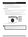
1. First, scan the entire object. Choose a scanning mode according to the shape of the scan object. From this point on, until
rescanning is finished, the mounted position of the scan object
must not be moved.
2. When you have finished scanning the entire object, click the
[Scan] button. A dialog box appears.
3. Click [Plane Rescan]. The Controller appears.
26
3. Finishing DetailedAreas Using Rescanning
4. Hold down the SPACE key and drag to position the
area you want to rescan at the front. This makes the
front surface the direction of laser-beam emission. As
you determine the orientation, try to angle it so that
the laser light can penetrate sufficiently.
SPACE key + drag left or right
to shift the perspective.
5. Drag (without holding down any keys) to specify the
rescanning area. The direction of plane scanning is
determined by the on-screen orientation at this time.
6. You can specify more than one rescanning area. To
do this, repeat steps 4 and 5. The scanning orientations are as you specify in step 5, resulting in scanning in more than one direction. (Note, however, that
the scanning pitch is identical for all directions.)
7. Enter a finer scanning pitch as required, then click
[Scan].
Drag to select the area to rescan.
This executes rescanning.
Shortcut Keys for Shifting the Perspective
You can also use the arrow keys to shift the perspective when specifying the rescanning area. Also, you can shift in parallel or zoom in or out
by holding down the CTRL key or the SHIFT key while dragging.
Specifying an Area and Rescanning
Clicking anywhere on the object after you have specified the rescanning area releases the area you specified. Also, even if you have performed rescanning, you can return to the state before rescanning by using the [Undo] button.
[Undo] button
Rescanning and the Scanning Pitch
When you’re rescanning a portion of a complex shape, making the scanning pitch as fine as possible increases the number of scanning points
and allows you to create more highly finished polygon mesh. When there is little free memory, it may be a good idea to use a narrow scanning
area and perform rescanning in several passes.
Choosing the Scanning Mode
When you’re rescanning an area that could not be scanned, plane rescanning is more effective than rotary rescanning. Scanning can be
accomplished in a shorter time than with rotary rescanning. Even when the scan object has a complex shape, it may be better to use plane
rescanning to perform overlapping scanning, changing the scan angle between each scanning pass.
27
Part 4 Features for Better Scanning
Scanning a Specific Area in Greater Detail
You perform coarse scanning of the entire object, then rescan just the required areas at a finer pitch. This can reduce the size of the data and
also shorten the scanning times. You choose either plane rescan or rotary rescan, according to the shape of the scan object. This section
describes how to perform rotary rescanning.
1. First, scan the entire object. Choose a scanning mode according to the shape of the scan object. From this point on, until
rescanning is finished, the mounted position of the scan object
must not be moved.
2. When you have finished scanning the entire object, click the
[SCAN] button. A dialog box appears.
3. Click [Rotary Rescan]. The Controller appears.
4. Hold down the SPACE key and drag to position the area you
want to rescan at the front.
5. Drag (without holding down any keys) to specify the rescanning
area. You can specify more than one scanning area.
6. Enter a finer scanning pitch, then go to the Controller and click
[Scan]. Rescanning starts.
Perform Rescanning in the Same Mode as the Basic Scan
When you’re rescanning a specific area at a fine scanning pitch, performing rescanning in the same mode as the basic scan makes it possible
to create data that more closely resembles the actual image.
For example, when you want to scan the surface pattern or the like in finer detail after performing coarse rotary scanning of a object that is
close in shape to a cylinder, it is a good idea to choose rotary rescanning.
28
4. Case Studies for Better Scanning
4. Case Studies for Better Scanning
Scanning Results for Objects That Are Difficult to Scan
These are some examples of scans of difficult materials. (The plated object was specially scanned for experimental purposes only. Avoid
highly reflective objects because of danger of eye injury.)
Black marker pen
Plane scanning
Pitch: 1.0 mm x 1.0 mm
Scanning errors occurred at
black areas.
Plated object
Rotary scanning
Pitch: 1.0 mm x 3 degrees
* In these cases, applying a white surfacer (primer) or the like may yield good results.
Choosing the Scanning Mode
This example involves using the two scanning modes to scan an object that has cavities and a complex shape. Plane scanning is suited to
objects like this.
Rotary Scan
Plane Scan
29
Part 4 Features for Better Scanning
This example involves using the two scanning modes to scan an object that has a nearly cylindrical shape. You can use either mode for
scanning, but rotary scanning achieves the shortest scanning times. The scanning pitch is equivalent for both, but rotary scanning produces
smoother surfaces.
Rotary scanning
Pitch of 1.4 mm x 1.6 degrees
Scanning time of 3 minutes 30
seconds
Plane scanning
Pitch of 1.4 mm x 1.4 mm
Scanning time of 6 minutes
This is an example of a polygon mesh generated after performing rotary scanning and rescanning, and a polygon mesh generated after
performing plane scanning. To determine which of the two modes to use, you should decide how much you want to take advantage of the
features of rotary scanning. Using plane scanning may eliminate the need to perform rescanning, but if smooth curves are important, then
rotary scanning may be more effective.
Rotary scanning
(with finishing by rescanning)
30
Plane scanning
(three scanning surfaces)
4. Case Studies for Better Scanning
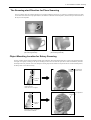
The Scanning-start Direction for Plane Scanning
This is an example where the scanning-start direction is changed with plane scanning. It is a good idea to consider the direction in which
cavities and voids can be most easily captured (that is, the direction in which the laser beam passes), and also to keep in mind what area of
the object is most important.
Example of starting from the front surface
(two scanning surfaces)
Example of starting from the front at an angle
(two scanning surfaces)
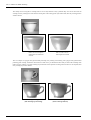
Object Mounting Location for Rotary Scanning
In rotary scanning, the laser light is beamed toward the center of the table. This means that when the object is uneven, the penetration of the
laser light varies greatly according to the object's mounting location. This case takes this point into account and deliberately shifts the
mounted position away from the center. Note that plane scanning may be better suited to an object like this one. At this mounted position,
the back portion is not scanned correctly.
Depression is a dead angle
for laser light, and so is not
scanned.
Center of
rotation
Plaster figure
Rotary scanning
Pitch: 0.6 mm x 1.0 degree
Scanning of the depression
is enhanced.
Center of
rotation
Plaster figure
Mounting position changed under the same conditions.
31
Part 5 Editing Scanning Results - Using 3D Editor
Part 5
Editing Scanning Results--Using 3D Editor
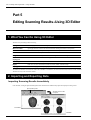
1. What You Can Do Using 3D Editor
3D Editor lets you do things like the following.
Enlarge and reduce
Deforming operations such as stretching in one direction are also possible.
Move and rotate
Specifying numerical values for the movement distance and angle of rotation is also possible.
Sever
You can divide an object into parts. Filling cut surfaces is also possible.
Delete
You can delete unneeded objects.
Merge
You can unite a number of objects. There is even an alignment feature for doing this.
Reduce the number
of polygons
This reduces the amount of data while keeping detail. This is an essential feature of 3D scanners.
Smoothing feature
This smooths the surfaces of objects.
Export
Data can be saved in such formats as DXF, STL, IGES, VRML, and Point Group.
Repolygonization
This creates a polygon mesh by using imported data.
The features of 3D Editor are described in detail in the "3D Editor User's Manual" (electronic-format manual). Refer to it as well. Note that
3D Editor can only work with surface models.
2. Importing and Exporting Data
Importing Scanning Results Immediately
In Dr. PICZA3, clicking the [Run 3D Editor] button starts 3D Editor and simultaneously imports the displayed scanning results.
[Run 3D Editor] button
3D Editor starts and data
is imported.
Dr. PICZA3
3D Editor
32
1. What You Can Do Using 3D Editor 2. Importing and Exporting Data
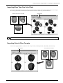
Importing More Than One Set of Data
You can use the [Import] button to import more than one set of data and place a number of object in the 3D Editor window. You can import
Dr. PICZA project format files, PIX-format files, DXF-format files (3D surface models only), and STL-format files.
Importing more than one set of data
PIX file
[Import] button
STL file
DXF file
3D Editor also supports importing for PIX-format files from Dr. PICZA versions 1 through 2.
Exporting Data in Other Formats
You can use the [Export] button to save data an a wide variety of formats, including DXF, STL, IGES, VRML, and Point Group.
[Export] button
Saving data in other formats
STL file
DXF file
VRML file
33
Part 5 Editing Scanning Results - Using 3D Editor
3. Basic Operations for Objects
How to View the 3D Editor Window
3D Editor displays an object from four different perspectives at the same time. You can manipulate any one of these at any time. The
important point is that you get four different views from four angles. However, each of the four windows has its own features.
Top
Perspective
This is a view of the object seen from directly above. You
can move only in the X and Y directions; there is no
movement in the Z-axis direction. Use this at times such as
when you want accurate movement in only the X and Y
directions.
You can move in all three directions (X, Y, and Z). Operations such as accurate movement in the X-axis direction are
difficult, and there is no way to tell how much movement is
made in the X, Y, and Z directions. It may be a good idea to
use this mainly as a viewer to visualize the entire object.
This indicates the X, Y,
and Z orientation.
34
Front
Side
This is a view of the object seen from directly in front. You
can move only in the X and Z directions; there is no
movement in the Y-axis direction. Use this at times such as
when you want an accurate view of movement along the Z
axis.
This is a view of the object seen directly from the side. You
can move only in the Y and Z directions; there is no
movement in the X-axis direction. Use this at times such as
when you want an accurate view of movement along the Z
axis.
3. Basic Operations for Objects
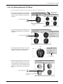
Let's Try Editing Data with 3D Editor
Let's try some simple editing. We'll scan an apple with the LPX-250, then try cutting and moving it.
3D Editor starts and
data is imported.
1. First, do a scan of an apple. Then, in Dr. PICZA3,
click the [Run 3D Editor] button. When 3D Editor
starts, the data for the apple is imported at the
same time.
[Run 3D Editor] button
Dr. PICZA3
3D Editor
2. Try cutting the apple vertically. Clicking the [Cut
at Plane] button displays the cut surface and a
dialog box.
[Cut at Plane] button
Drag.
3. Try shifting the cut location a little to one side.
This may be easiest to do in the [Front] window.
Drag the cut surface to move it to the left.
Click this to
make the cut.
4. When you have decided on the cut location, click
[Run]. The apple is divided into two parts. However, its still looks like a single object. Try separating the two parts. Click the [Select Object]
button, then click the left part of the apple to select it.
[Select Object] button
Click this portion
to select it.
35
Part 5 Editing Scanning Results - Using 3D Editor
5. Click the [Move Object] button, then drag the portion you selected to the left. The two parts separate. When you're done
with the operation, right-click to quit the [Move Object] mode.
[Move Object] button
Drag the object you
want to move.
6. Now try orienting the cut surface of the apple on the right to face
the front. You can only do this when you're in the [Top] window.
First click the [Select Object] button, then click the right side of
the apple to select it.
Click this portion
to select it.
[Select Object] button
7. Click the [Rotate Object] button, then drag to turn the object
counterclockwise. Try turning it until the cut surface faces down.
Look at the [Perspective] window to see how the cut surface
faces the front. When you're done with the operation, right-click
to quit the [Rotate Object] mode.
[Rotate Object] button
Drag to rotate.
8. Finally, try deleting the cut part. You can do this in any window
except the [Side] window. First click the [Select Object] button,
then click the cut-off portion to select it. Then click the [Erase]
button.
[Erase] button
[Select Object] button
36
Part 6
Troubleshooting
If operation is not as expected, try taking corrective action as described below. If that doesn't correct the problem, or if you determine that there is a
breakdown, then contact your authorized Roland DG Corp. dealer or service center.
Symptom
Remedy
If the problem persists
The power does not come on
- Make sure the AC adapter and power cord are connected correctly.
The scanner unit or the AC adapter
when the Standby key is
- Unplug the AC adapter from the electrical outlet, redo the connections,
may be broken, or there may be a
pressed.
The power does not go off
then press the Standby key.
broken wire in the power cord.
- Unplug the AC adapter from the electrical outlet.
when the Standby key is held
down for 1 second or longer.
When the power is turned on
- Make sure all the head retainers have been removed.
an unusual sound is heard for
- Make sure no scan objects or other items are caught inside the machine.
The scanner may be broken.
about 40 seconds.
When the power is switched on - Make sure all the head retainers have been removed.
the Standby key lights up
green, but scanning cannot be
performed.
- Make sure the correct COM port number is set in the preferences for Dr.
PICZA3.
The cable used for the connection
with the computer may not be the
right kind or may be broken. Alter-
- Restart the computer.
natively, the computer's COM port
- Make sure the connection to the computer is correct.
may not be functioning, or the scan-
- Unplug the scanner's AC adapter from the electrical outlet, redo the con-
ner unit may be broken.
nections, then switch on the power.
When the power is switched on
- Close the door securely.
the Standby key flashes green
- Unplug the AC adapter from the electrical outlet, redo the connections,
and there is no movement at all.
The Standby key flashes
then switch on the power.
- First start the computer, then switch on the power to the scanner unit.
orange and scanning cannot be - Restart the computer, then reset the power to the scanner unit.
performed.
The scanner may be broken.
- Unplug the scanner's AC adapter from the electrical outlet, redo the connections, then switch on the power.
The cable used for the connection
with the computer may be faulty or
there may be faulty contact at one
of the connectors.
- Make sure the right kind of cable is used for the connection with the
computer.
- Reinstall the program.
The Standby key flashes (or
lights up) red.
- Unplug the AC adapter from the electrical outlet, redo the connections,
The scanner may be broken.
then switch on the power.
Scanning ended, but the
- Scanning that exceeds the amount of free memory in the computer may
computer then stopped.
drastically impair the performance of the computer. In Dr. PICZA3, go
to the [Settings for Scanning] dialog box and check the amount of required memory, and consider increasing the scanning pitch or installing
more memory.
37
Part 6 Troubleshooting
Symptom
Remedy
If the problem persists
The message "Cannot commu-
- Switch on the power to the scanner before you run Dr. PICZA3.
The cable used for the connection
nicate with present scanner"
- Make sure the correct COM port number is set in the preferences for Dr.
with the computer may not be the
appears on the computer and
there is no operation.
PICZA3.
natively, the computer's COM port
- Make sure the connection to the computer is correct.
may not be functioning, or the scan-
- Unplug the scanner's AC adapter from the electrical outlet, redo the
ner unit may be broken.
connections, then switch on the power.
- Reinstall the program.
The message "COM:** not
- Restart the computer.
ready" appears on the com-
- Unplug the scanner's AC adapter from the electrical outlet, redo the
puter.
connections, then switch on the power.
- If you're using Windows NT/2000/XP, make sure no other printer driver
or the like is using the same COM port.
- Reinstall the program.
The message "Can’t find
- The buttons for running these do not function on this system. They become
MODELA Player" or "Can’t find
available when you are using together with the MODELA series or the
3D Engrave" appears on the
like.
computer.
38
right kind or may be broken. Alter-
- Restart the computer.
1. Sample Data Sheet
Part 7
Appendix
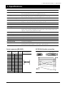
1. Sample Data Sheet
This is a data sheet from an actual scan. Refer to it when you are setting scanning conditions.
Object
Material: plaster
Scanning mode
Rotary scanning
Scanning area
Height direction 0 to 325 mm, Circumferential 0 to 360 degrees
Scanning pitch
Height direction 1.0 mm, Circumferential 1.0 degrees
Scanning time
Approx. 23 minutes
Memory used
Approx. 53 MB (estimate of use by Dr.PICZA3)
Data size
Dr. PICZA project format
7.6 MB (included polygonmesh data)
PIX format (text)
5.1MB
DXF format
23.1MB
STL text format
64.5 MB
STL binary format
11.0 MB
IGES format
724 KB (portion of bust front; 6,724 control points)
VRML format
7.7 MB
3DMF format
7.5 MB
* All the data size is the result exported from the scan data.
Computer
Windows 98, PentiumIII 650 MHz, 320 MB RAM
39
Part 7 Appendix
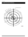
2. Table Dimensional Drawing
9 screw holes (M6, depth 7 mm)
φ 60
φ1
30
φ2
00
φ
25
4
12
0
de
gr
120
deg
ree
ee
40
2. Table Dimensional Drawing 3. Specifications
3. Specifications
Table size
Diameter 254 mm (10 in.)
Maximum scanning area
Rotary scanning: Diameter 254 mm (10 in.), height 406.4 mm (16 in.)
Plane scanning: Diameter 230 mm (9 in.), height 406.4 mm (16 in.)
Scanning pitch
Rotary scanning: circumference 0.2 to 60 degrees, height direction 0.2 to 406.4 mm
Plane scanning: width direction 0.2 to 230 mm, height direction 0.2 to 406.4 mm
Maximum table load weight
5 kg (11 lb.) (not including optional vise)
Laser
Wavelength: 600 to 700 nm, maximum output: less than 1.0 mW (maximum output discharged outside
housing is 0.39 µW), pulse width: 350 µs, pulse frequency: 2,857 Hz
Sensor
Noncontact laser sensor
Scanning method
Spot-beam triangulation
Operating speed
Table rotation speed: 15 rpm, head rotation speed: 7.5 rpm, head movement speed: 50 mm/sec.
Interface
Serial (RS-232C standard, D-Sub 25 pin)
Transfer method: Asynchronous/full duplex data communication, 9,600/115,200 bps transfer speed,
8 data bits, 1 stop bit, no parity, hardware flow control
Control keys and LEDs
Standby key, Standby LED, and Movement LEDs
Power consumption
Dedicated AC adapter (DC 19 V, 2.1 A)
External dimensions
528 (W) x 742 (D) x 431 (H) mm (20-13/16 (W) x 29-3/16 (D) x 16-15/16 (H) in.)
Weight
32 kg (70.5 lb.) (main unit only)
Operating temperature
10 to 40 ˚C (50 to 104 ˚F)
Operating humidity
35 to 80% (no condensation)
included items and accessories
AC adapter: 1, power cord: 1, 2.5-mm hexagonal wrench: 1, 3-mm hexagonal wrench: 1, caps: 3,
Roland Software Package CD-ROM: 1, user's manual: 1, Roland Pixform™: 1
Serial connector (RS-232C)
Signal
number
Terminal
number
Signal
number
NC
25
13
NC
NC
24
12
NC
NC
23
11
NC
NC
22
10
NC
NC
21
9
NC
DTR
20
8
NC
NC
19
7
SG
NC
18
6
DSR
NC
17
5
CTS
NC
16
4
RTS
NC
15
3
RXD
NC
14
2
TXD
1
FG
XY-RS-34/14 cable connection
Pin connection
D-sub 9 pin
D-sub 25 pin
41
Please read this agreement carefully before opening the sealed
package or the sealed disk package
Opening the sealed package or sealed disk package implies your acceptance of the terms and conditions of this agreement.
Roland License Agreement
Roland DG Corporation ("Roland") grants you a non-assignable and non-exclusive right to use the COMPUTER
PROGRAMS in this package ("Software") under this agreement with the following terms and conditions.
1. Coming into Force
This agreement comes into force when you purchase and open the sealed package
or sealed disk package.
The effective date of this agreement is the date when you open the sealed package
or sealed disk package.
2. Property
Copyright and property of this Software, logo, name, manual and all literature
for this Software belong to Roland and its licenser.
The followings are prohibited :
(1) Unauthorized copying the Software or any of its support file, program module
or literature.
(2) Reverse engineering, disassembling, decompiling or any other attempt to
discover the source code of the Software.
3. Bounds of License
Roland does not grant you to sub-license, rent, assign or transfer the right granted
under this agreement nor the Software itself (including the accompanying items)
to any third party.
You may not provide use of the Software through time-sharing service and/or
network system to any third party who is not individually licensed to use this
Software.
You may use the Software by one person with using a single computer in which
the Software is installed.
4. Reproduction
You may make one copy of the Software only for back-up purpose. The property
of the copied Software belongs to Roland.
You may install the Software into the hard disk of a single computer.
5. Cancellation
Roland retains the right to terminate this agreement without notice immediately
when any of followings occurs :
(1) When you violate any article of this agreement.
(2) When you make any serious breach of faith regarding this agreement.
6. Limitations on Liability
Roland may change the specifications of this Software or its material without
notice.
Roland shall not be liable for any damage that may caused by the use of the
Software or by exercise of the right licensed by this agreement.
7. Governing Law
This agreement is governed by the laws of Japan, and the parties shall submit to
the exclusive jurisdiction of the Japanese Court.
R3-030418