1
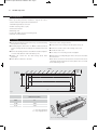
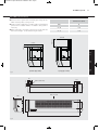
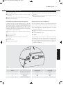
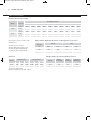
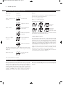
23674 HiLine Super RC manual 27/06/2011 09:24 Page 2
Installation, Operating, Maintenance
and After Sales Manual.
HI-LINE Super RC
Models: 25-18, 29-20
heatingthroughinnovation.
01.06.2011 ISSUE 4
Product Serial Number:
Please leave this manual with the end user.
Part Number: 1370065
Issue 4
23674 HiLine Super RC manual 27/06/2011 09:24 Page 3
Contents
1.0
General Information
03
2.0
Heating System Design
03
3.0
Unit Selection/Sizing
03
4.0
Location
03
5.0
Preparation
04
6.0
Fixing
04
7.0
Water Connections
05
8.0
Electrical Connection
06
9.0
Commissioning Procedure
07
10.0
Technical Data
08
11.0
Operating Instructions
09
12.0
Troubleshooting
10
13.0
Maintenance
11
23674 HiLine Super RC manual 27/06/2011 09:24 Page 4
HI-LINE Super RC
03
Automatic – the desired room temperature is programmed in
to the unit and the fan speed is automatically adjusted until
the desired room temperature is achieved.
l The minimum installation height is 1.8m to the underside of
the unit.
Fan only – allows user selection of any of the 3 available fan
speeds irrespective of room temperature or water temperature
in the coil.
Fan only with water temperature control – allows the user to
select any of the available fan speeds, which will operate only
if the water temperature in the coil is above 32C. This enables
control of the unit via an externally mounted room thermostat
if desired.
3.0
l Before proceeding with the installation, the heating system
design must be considered and the unit correctly sized to
meet the heat loss requirements of the room at normal fan
speed.
l This appliance is not intended for use by persons (including
children) with reduced physical, sensory or mental
capabilities, or lack of experience and knowledge, unless
they have been given supervision or instruction concerning
use of the appliance by a person responsible for their safety.
4.0
l The minimum clearance between the top of the unit and the
ceiling should be 20mm for rear pipe connection or 100mm
for connection from above.
2.0
l This MYSON HI-LINE Super RC fan convector is designed for
wall-mounted installation with a maximum installation height
of 3m to the underside of the unit.
1.0
1.0 General Information
l This unit is supplied with an infra red remote control system
and has 3 operating modes -
Children should be supervised to ensure they do not play with
the appliance.
l The minimum side clearance is 150mm.
l The HI-LINE Super RC should only be used on closed
circulation, two pipe, pump assisted central heating systems.
This unit MUST NOT be installed in a bathroom or other similar high humidity area.
2.0 Heating System Design
This fan convector must be fitted on a two pipe, pumped
circulation heating system.
For optimum fan convector heating performance the system
must be capable of providing sufficient hot water through the
heat exchanger. This means that:
1. The minimum pipe size from boiler to fan convector must be
at least 22mm.
2. This unit is not suitable for use on microbore pipework.
4. The system water must be above 32°C for heating mode.
5. For heat pump applications - see Commissioning Procedure.
6. This unit is NOT suitable for one-pipe systems.
7. Optimum performance will require effective balancing of
the whole system.
8. This unit should NOT be used to replace a radiator in an
existing system unless an adequate flow of water can be
guaranteed.
3. Where the unit is fitted on to a system with other emitters a
separate circuit for the fan convector should be considered
to provide adequate water flow.
3.0 Unit Selection/Sizing
Heat output performance is given in the Technical Data section
of this manual. Outputs are shown for the 3 fan speeds,
however, it is important to size the unit to match the calculated
heat loss requirements of the room with the unit operating on
the low fan speed. The higher fan speeds are used in automatic
mode when the room temperature is significantly lower than the
preset temperature.
4.0 Location
l This HI-LINE Super RC unit may be fitted to any convenient
wall at a height from floor level that suits the application,
providing an unimpeded flow of warm air into the area to be
heated.
l The maximum distance from the underside of the unit to floor
level is 3m.
l The minimum distance to the underside of the unit is 1.8m.
l This unit should not be installed in locations with ceiling
heights greater than 3.5m.
l The unit should be mounted on a flat wall, and stud or
partition walls should be avoided to minimise the possibility
of noise transmission.
23674 HiLine Super RC manual 27/06/2011 09:25 Page 5
04
HI-LINE Super RC
5.0 Preparation
Before proceeding with the installation, unpack the carton
contents and check against the checklist below:
1. HI-LINE Super RC fan convector.
2. 22mm isolating valves (1 pair).
3. Instruction manual.
4. Warranty card.
5. Fixing kit (rubber mounts and cable gland).
6. Remote control handset.
6.0 Fixing
l Using the fixing dimensions below (see fig. 1), mark the fixing
hole positions on the wall.
Remove the outer casing as follows:
l Remove the screw securing each side panel (see fig. 2).
l Drill and plug the wall for No. 8 x 40mm round head wood
screws ensuring that the wall plugs are suitable for the wall
type.
l Remove 2 screws at each side securing outer cover.
l Lift off the outer case.
l Remove the backing from the self-adhesive washers and place
on screws with adhesive side towards the point.
l Fit chassis on to mounting screws and tighten.
l Tighten the screws into the wall leaving about 9mm
projecting.
Note: Before proceeding with pipe-work connections check that
the unit is level.
l Press adhesive washers to the wall.
When water connections and electrical connections have been
completed and the unit has been vented, fit the outer cover and
secure with fixing screws.
Ceiling
150 min
each
side
92
275
144
77
a) 20 min
b) 100 min
63
53
103
A
Fig. 1
Dimensions (mm)
Unit
A
29-20
1360
25-18
1150
a = rear entry pipework
b = top entry pipework
Fig. 2 Case fixing screw positions
23674 HiLine Super RC manual 27/06/2011 09:25 Page 6
HI-LINE Super RC
05
7.0 Water Connections
l Connect unit to system flow and return pipes using the two
22mm isolating valves (see fig. 3 & 4).
Dimensions (mm)
l Ensure system is flushed in accordance with recognised best
practice and a suitable inhibitor is added to the system as
necessary.
l Open valves fully, check pipe connections for leaks and vent
the heat exchanger - see Commissioning Procedure.
Unit
A
29-20
1378
25-18
1168
100 mm min
CEILING
a) Rear pipe entry
7.0
6.0
5.0
20 mm min
CEILING
b) Top pipe entry
82
69
55
117
55
Mains cable entry
201
23
21
Fig. 3
View on arrow
108
275
128
203
A
Fig. 4
23674 HiLine Super RC manual 27/06/2011 09:25 Page 7
06
HI-LINE Super RC
8.0 Electrical Connection
WARNING: This appliance must be earthed. The electrical installation must comply with local or national
wiring regulations.
l This unit is supplied with factory fitted test leads. Remove
these and discard.
l A fused electrical spur with a maximum 3A fuse and a switch,
having 3mm separation on all poles, must be provided in an
easily accessible position adjacent to the unit.
l Connect live and neutral wires to the power board terminal
connections, and the earth wire to the chassis earth terminal
(see wiring diagram).
l Electrical cable entry to the unit should be made through the
hole provided at the top left hand side of the unit, using the
cable gland provided.
Wiring diagram
LN
O O
OO
Motor
Brown
Blue
Power Board
Air Sensor
Water Sensor
Control Board
23674 HiLine Super RC manual 27/06/2011 09:25 Page 8
HI-LINE Super RC
07
9.0 Commissioning Procedure
l Fill and vent the system.
l Open both valves fully and check for leaks at pipe
connections.
l Refit the outer case and secure using the 2 fixing screws.
l Check the operation of the unit by following the operating
instructions.
l When installation and commissioning are complete, hand over
instruction manual to end-user.
l Switch on electrical supply.
Heat Pump and Low Water Temperature Systems
Displayed Temperature Calibration
In heating mode, the control system brings the fan on when the
water in the coil reaches 32°C. For low water temperature systems,
eg heat pump systems, it is possible to switch off the boost speed
option in automatic mode so that the unit runs in medium or normal
fan speeds depending on demand. This means low outlet air
temperatures from the unit are avoided when the room temperature
is low in relation to the set temperature.
This function enables calibration of the displayed temperature
to the actual room temperature using the following procedure:
This facility can be switched on or off by following the instructions
below
l Isolate electrical supply.
l Press the On/Off key and + key simultaneously for 5 seconds.
The display will flash, alternating between ‘ro’ and the
calibration temperature.
l Calibrate the displayed temperature by using the + and –
keys.
l Press the On/Off key to finish.
Fan Pulse
l Remove outer cover.
l Change switch 1 position according to requirements
(see fig. 5).
l Refit outer cover.
9.0
8.0
l Switch on electrical supply.
Fan pulse mode causes room air to be drawn over the air
temperature sensor periodically to maintain room temperatures
more effectively. In certain circumstances, for example when
units are over-sized in relation to the heat loss of the room, it
may be necessary to turn off this function. Use dipswitch 3
according to requirements.
Fig. 5
Switch
Switch Down
Switch Up
1
Auto Fan Speed Selection
2 Speed
3 Speed
2
Heating / Cooling
N/A
Heating
3
Fan Pulse
Off
On
4
Temperature Display
°F
°C
23674 HiLine Super RC manual 27/06/2011 09:25 Page 9
08
HI-LINE Super RC
10.0 Technical Data
Heating Performance Data
Heat Output (watts)
Model
Temperature Difference °C (Δt)
Fan Speed
29-20
25-18
20°
25°
30°
35°
40°
45°
50°
55°
60°
65°
Normal
1858
2360
2870
3385
3906
4432
4962
5496
6033
6573
Medium
Boost
2234
2599
2843
3313
3462
4040
4089
4778
4723
5526
5364
6282
6011
7045
6622
7815
7319
8591
7980
9373
Normal
Medium
Boost
1709
1962
2172
2136
2492
2804
2563
3030
3454
2990
3574
4120
3417
4124
4800
3843
4679
5500
4270
5238
6200
4697
5802
6900
5123
6369
7600
5550
6939
8400
Approximate Hydraulic Resistance through Fan Convectors
Heat outputs tested in accordance with
BS 4856 Part 1.
Litres/h
Flow Rate Correction Factors:
455 ltr/h (100 gal/h) multiply by 1.03.
227 ltr/h (50 gal/h) multiply by 0.98.
113 ltr/h (25 gal/h) multiply by 0.85.
455
340
227
113
Air Flow
Model
mm wg
kPa
25- 18
29- 20
25- 18
29- 20
2095
1282
620
234
2551
1530
850
245
20.5
12.6
6.1
2.3
24.6
15.0
8.3
2.4
Weight, Water Content and Motor Power
Air Flow (m3/h)
Normal Medium
Boost
Air Flow (ft3/h)
Normal Medium
Boost
Model
Motor
Power (W)
Water
Content (l)
Unpacked
Weight (kg)
29-20
390
470
540
13772
16597
19069
29-20
80
0.85
21.0
25-18
350
430
500
12360
15185
17657
25-18
80
0.63
18.0
Test Pressure 20bar (2MPa)
Maximum Working Pressure 10bar (1MPa)
23674 HiLine Super RC manual 27/06/2011 09:25 Page 10
HI-LINE Super RC
09
11.0 Operating Instructions
Description
This HI-LINE Super unit is fitted with a control system that
provides either automatic or manual control of the unit. In
automatic mode the desired temperature set point is selected
and the unit will adjust the fan speed according to the difference
between the actual room temperature and the set point. When
the room temperature reaches the set point the fan will switch off
and thereafter will continue to cycle on and off to maintain the
room temperature. The temperature set point range is 15 - 35°C.
In manual mode, with water temperature control, any of the 3
fan speeds can be selected and the fan will operate when the
water temperature in the coil is greater than 32°C. This means
that heating performance can be controlled manually, and the
unit could be controlled via an external room thermostat.
The unit can be controlled using the infra red remote control
handset supplied with the unit (see fig. 6) and also using the
control panel on the unit (see fig. 7). If necessary, however, the
control panel can be locked electronically to prevent tampering
once the controls have been set (see below).
In manual mode the automatic temperature control is
overridden and any of the three fan speeds can be operated
inrespective of the water temperature in the unit. This means
that air circulation can be provided in summer for example, or
that heating performance can be controlled manually.
Fig. 6
Fig. 7
Display
Heating
Power button
Switches unit on & off
‘+/-’ button
Adjust temperature set point from
15 - 35°C
Scrolls into F1, F2 or F3 manual mode
Heating will only be provided when the central heating
boiler is on, the pump is running and the system water
temperature is greater than 32°C. Ensure the boiler is on,
and set timer, boiler controls and room thermostats as
necessary.
11.0
Controls
10.0
The remote control hand set takes 2 AAA batteries (not supplied).
23674 HiLine Super RC manual 27/06/2011 09:25 Page 11
10
HI-LINE Super RC
11.0 Operating Instructions
(continued...)
Operation
Display
Manual
Power off
No Display
Manual mode can be used for air circulation without heat or for
manual control of the heating function.
Switch on supply to unit
(unit off)
for 30 seconds
Use ‘+’ to scroll beyond 35°C
Or use ‘-’ to scroll below 15°C
Selected fan speed displayed
Supply on / unit off
Continuous
fan only
Switch on unit
Set point flashes for
5 secs, then
Ambient temperature
displayed
Fan & water
temperture
(water inlet >32°C)
Scrolling back out of manual using the ‘+’ or ‘–’ button will revert
the unit back to last temperature set point.
Locking Unit Controls
Use ‘+/-’ to adjust
set point
Set point flashes for
5 secs, then
Ambient temperature
The ambient temperature is always displayed unless the water
temperature falls below 32°C*, or if the set point is being
adjusted.
Water temp <32°C
The control panel on the main unit can be locked electronically
to prevent interference once the controls have been set. After
setting the unit to the desired temperature setting and with the
unit in running mode, press the On/Off button on the main unit
for about 6 seconds until the two middle horizontal bars appear
on the display. The horizontal bars will disappear after about 6
seconds and the unit is in key lock mode.
If any of the unit controls are pressed the horizontal bars will
reappear to show the key lock mode is activated, however,
during this mode the handset controls remain functional.
To unlock the system press the On/Off button for about 6
seconds until the horizontal bars disappear.
Shows both power
& unit on
*32°C in heating and above 20°C in cooling.
12.0 Troubleshooting
Once installed this fan convector becomes part of a complete
heating system that generally will include boiler, pump, other
emitters such as radiators and fan convectors, and a number of
heating controls, dependent on system complexity. An apparent
problem with this unit may be the result of system controls being
incorrectly set and can be solved easily without calling out your
installer or MYSON Service. Before calling your installer or
MYSON Service, please carry out the checks listed opposite.
Note: If you call out MYSON Service to a fault detailed opposite,
or to repair a fault caused by incorrect use, a call out charge will
be made.
23674 HiLine Super RC manual 27/06/2011 09:25 Page 12
HI-LINE Super RC
12.0 Troubleshooting
11
(continued...)
Problem
Possible Causes
Remedy
Unit switched off
Turn on
Temperature set point reached
Increase temperature set point
Unit not switched on at fused spur
Switch on at spur
Heating Mode -
Fuse blown at fused spur
Replace fuse
No Fan
Unit isolating valves shut
Open valves
Water temperature reaching fan
convector below 32°C
(Heater model only)
Check boiler Programmer ON
Boiler ON and set to high with central
heating pump running
Note: Operation of fan convector can be checked by
switching to manual fan setting
Heating Mode
Low water temperature to unit
Turn up boiler thermostat
Poor water flow
Vent air from heating system
(Heater model only)
poor heating
performance and/or
unit cycles on
water sensor
If the fan convector is still faulty after checking the above, call your installer or MYSON Service.
Common Installation Faults
For optimum performance, this unit must be correctly sized to
match the heat loss requirements of the space it is required to
heat, and the heating system must be correctly designed to
provide adequate flow of hot water to the unit (see Section 2).
If the recommendations in Section 2 are not followed,
problems may arise as detailed below.
Problem
Possible Causes
Poor heating performance
Unit incorrectly sized for heat loss of room
(Heater model only)
Boiler thermostat set too low
Heating Mode
(Heater model only)
poor heating
performance and/or
unit cycles on
water sensor
Lack of flow to fan convector Pump set on low setting
Isolating valves not fully open
System incorrectly balanced with unit starved of hot water flow
11.0
Pipe sizing to unit too small
Maintenance should be restricted to occasional removal of dust
and lint around the unit. The outer surface may be wiped over
with warm water and mild detergent taking care to avoid water
entering the grille areas.
13.0
Before undertaking any maintenance activity isolate the
electrical supply.
12.0
13.0 Maintenance
23674 HiLine Super RC manual 27/06/2011 09:24 Page 1
MYSON Eastern Avenue, Team Valley, Gateshead, Tyne & Wear NE11 0PG, UK
T: 0845 402 3434, F: 0191 491 7568, [email protected], www.myson.co.uk
Serial Number Location:
Inner chassis position
heatingthroughinnovation.
After Sales Service:
Spare parts and technical help on all Convector products are available from MYSON Service.
01.06.2011 ISSUE 4
MYSON Service, Somerden Road, Hull, East Yorkshire HU9 5PE
T: 01482 713927, F: 01482 789056, [email protected]