1
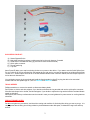
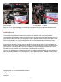
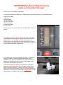
HCP9982 Battery Sensor Bypass Device
INSTALLATION INSTRUCTION SHEET
Thank you for your purchase of this product.
It is designed to eliminate or replace your original battery fluid-level sensor device on the following models:
XJ650 Police models
XJ650 Turbo
XJ750-D models
1982 XJ750 Maxim
1981-83 XJ750 Seca
XJ750 11M models
XJ750 Police models
XJ1100 models
and other models from this era using an LCD display panel for various
sensors.
Your original sensor is a low-fluid level sensor, which screws into a
specific battery cell "filler cap" port, typically the third over from the
positive terminal, and will trigger the warning icon (and the red
warning light) on your dash when the fluid level falls below a certain
level. In short, the original sensor serves as a reminder to the operator
to check the fluid level when it gets too low.
On the other hand, if you buy a replacement "sealed", maintenancefree type of battery, an aftermarket battery which does not use
threaded fill caps (thank you, WalMart!), or the caps provided use a
different size threaded port, then one can’t use the original sensor.
That’s where this bypass device comes in.
This replacement sensor bypass device solves all of the above
problems, as well as providing a more meaningful measurement of
battery condition (its voltage). Although it no longer will notify you
directly of a low-fluid level condition (since it is not immersed into the
battery fluid), it will notify you of a low battery voltage level, no matter
what the cause -- including, of course, one caused by low fluid.
1
INCLUDED IN YOUR KIT:
A)
B)
C)
D)
E)
F)
Sensor Bypass Device
Male bullet terminal to replace a missing terminal on the main harness, if needed
Small section of heatshrink tubing (if you need to use the bullet terminal)
Quick splice connector
Female spade lug
2 zip ties
Items D) and E) allow you to tap into existing circuits to run power to the device. If you want to use the Quick Splice (item
D), you could cut off the ring terminal from the bypass device, and use it to connect the bypass to an existing wire that has
12 volts on it. Another option would be to cut off the sheathed female bullet connector instead, and use the quick splice to
tie into the main harness wire.
You could also remove the ring terminal and install the female spade lug (item E) to plug the device into a terminal
fusebox that has male spade lugs on it, like our HCP378 and HCP7153 models.
TOOLS NEEDED:
Phillips screwdriver or correct size wrench to disconnect battery leads.
Pair of pliers or similar, and wire strippers, if you decide to eliminate the ring terminal and use the quick splice connector.
Wire terminal crimper tool or similar, and wire strippers, if you decide to replace the ring terminal with the insulated female
spade lug included.
Not required, but a factory or aftermarket service manual in case you need guidance for parts removal or a wiring harness
schematic.
PRECAUTIONARY NOTES:
Do not over tighten any connectors, and check the routing and condition of all existing bike wiring you see as you go. It is
very important that all wiring is not being rubbed or pinched between other bike parts, or allowed to hang loose and flop
around.
2
Clean all connection surfaces with fine sandpaper. If you find your battery terminals are covered with some kind of
protective grease, you must clean and remove all of this material before re-attaching any wires. Then re-apply a protective
grease or similar product, if desired, when you're finished.
INSTALLATION:
Installation is quite simple.
A) First, DISCONNECT
THE POSITIVE CABLE FROM YOUR BATTERY!!
B) If your battery is currently using a fluid-level sensor, seen
here, disconnect the sensor from its main harness connector
plug (a white wire with a red tracer stripe, terminated with a
male "bullet" style terminal, middle picture).
C) You may leave your sensor screwed into the battery, where
it will act as a fluid cap, or remove it and replace it with an
appropriate sized standard fluid cap.
D) If your battery is missing its sensor, or if it was not possible
to fit a sensor into your battery, locate the original sensor lead
wire on the main wiring harness. This is a single white wire
with a red tracer stripe, and is terminated with a male "bullet"
style terminal. This wire is typically located very near the
battery, although its exact position varies on different model
bikes. It is the ONLY white wire with a red tracer stripe in your
harness.
PLEASE NOTE: if the original bullet end terminal has been
removed, you will have to install the proper male bullet wireend terminal (included) onto the end of the above lead wire.
Crimp, solder for good measure, then add dielectric grease
and the supplied section of heatshrink.
E) Clean the original bullet connector to make sure it is free of
corrosion or any other build up. Apply some protective dielectric grease or similar to make sure that corrosion will not
build up in the future, as increased electrical resistance in this
connector will alter the performance of the computer monitor.
F) Plug the male bullet terminal from the main harness lead
wire into the sheathed female bullet on the bypass harness.
G) Carefully route the bypass harness as needed. The closed ring terminal on the other end of the harness can be
connected directly to the positive battery terminal, or to the input post on the starter motor relay/solenoid unit (the input
terminal is the one that is hooked directly to the battery positive post). Installing the ring terminal to the solenoid input
post has the advantage of not requiring you to undo this wire if and when you remove your battery from your bike. (See
the pictures on the next page.)
In either case, make SURE that where you connect the ring terminal is clean, and free of rust or corrosion. The use of
some di-electric grease or similar protectant over the terminal, post, attaching hardware, and the ring terminal is strongly
recommended.
H) Reconnect the positive battery cable.
3
Positive terminal…
…or starter solenoid. You decide.
Either way, you can use the included zip ties to bundle the wiring together and tuck it up underneath the frame so it sits
behind/on top of the airbox, out of the way.
AFTER YOU’RE DONE:
The original sensor and this sensor bypass device is not active until the ignition switch is set to the ON position.
This bypass device will pass battery voltage to the computer monitor circuit, and will cause the BATT warning word or icon
on the dash LCD display panel and the red warning light to come on whenever the battery voltage is below about 12 volts.
Therefore, if the battery voltage has been reduced for any reason (such as excessive cranking, left lights on by mistake,
short circuit, weak battery, etc.) the BATT warning word or icon and warning light will display until the battery voltage
returns to normal.
So, you may find that the BATT warning word or icon and the red warning light may display for a few moments after first
starting the bike, since the battery voltage has been "drained" via the use of the starter motor; but the voltage should soon
return to normal. At that point, the BATT icon on the LCD display should go out (although you may still have to shut off
the red warning light by yourself) if your charging system is working the way it’s supposed to.
Of course, you can always use the "warning light reset" button to disable the red warning light on your dash (push once to
stop it from flashing; push again to turn it off completely) if you find it bothersome; however, in case of low battery voltage
(or any other error condition), the proper dash icon will remain displayed until the failure is remedied.
copyright xj4ever.com and Schmuckatelli Heavy Industries
[email protected]
HCP14180.doc
10/12/2010
4