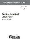
1
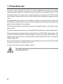
OPERATING INSTRUCTIONS Version 07/09 Switch module „FS20 SH-2“ (for FS20 DIN rail system) Item no. 62 30 15 Introduction Dear customer, Thank you for purchasing this product. This product meets the requirements of both current European and national guidelines. In order to preserve this condition and ensure the safe operation of the product we kindly ask you to carefully follow these operating instructions! Please read the operating instructions completely and observe the safety and operation notes before using the product! All company names and product names contained herein are trademarks of the respective owners. All rights reserved. Should you have any further questions, please contact our technical advisory service: Germany: Tel. no.: +49 9604 / 40 88 80 Fax. no.: +49 9604 / 40 88 48 e-mail: [email protected] Mon. to Thur. 8.00am to 4.30pm Fri. 8.00am to 2.00pm 2 Table of contents Page 1. 2. 3. 4. 5. 6. 7. 8. 9. 10. 11. 12. 13. 14. 15. Prescribed use ............................................................................................................... 4 Scope of delivery ........................................................................................................... 5 Features and specifications .......................................................................................... 5 Safety instructions ......................................................................................................... 6 Controls, connections .................................................................................................... 8 Preparation .................................................................................................................... 9 Installation .................................................................................................................... 10 Programming ............................................................................................................... 13 a) Initial operation ..................................................................................................... 13 b) Programming ........................................................................................................ 13 c) Operation with remote control .............................................................................. 15 d) Direct mode ........................................................................................................... 15 Timer functions ............................................................................................................ 16 a) General information .............................................................................................. 16 b) Programming the timer ......................................................................................... 16 c) Operating the timer ............................................................................................... 17 1. Starting the timer ........................................................................................... 17 2. Prematurely stopping the timer ..................................................................... 17 3. Deactivating the timer function ..................................................................... 17 4. Deactivating/activating the programmed timer ............................................ 17 Resetting to the delivery state .................................................................................... 18 Handling ....................................................................................................................... 19 Maintenance ................................................................................................................ 19 Disposal ....................................................................................................................... 20 Miscellaneous .............................................................................................................. 20 Technical specifications .............................................................................................. 20 3 1. Prescribed use The switch module ‘FS20 SH-2’ is meant to be used in a FS20 DIN rail system It can operate loads (for supply voltage 230V~/50Hz) that can go up to 3680VA (corresponds to 230V~, 16A). The switch module can function both via existing buttons on a device and a FS20 wireless control system remote control and via various remote switch transmitters (range goes up to 100m). A programmable timer function is also available in addition to a switch function (on-time can last between 1 second and 4.5 hours). Once the programmed timer duration has elapsed, the switch module switches off automatically. All the programmed data is permanently stored in an integrated memory, even when a power failure occurs. The switch module must be set up on a standard DIN rail within house- and sub-distributions. The power and the switching signal are delivered by the ‘FS20 ESH’ power supply. The receiver ‘FS20 EAM’ receives the radio signals in conjunction with the ‘FS20 ESH’ power supply (these components are not included with the switch module ‘FS20 SH-2’ and must be ordered separately). Any use other than the one described above may damage the product and can also increase the risk of short-circuit, fire, electric shock, etc. No part of the product may be modified or rebuilt. The safety instructions and installation notes in this user manual must be observed without fail. 4 2. Scope of delivery • Switch module ‘FS20 SH-2’ • User manual 3. Explanation of icons The icon with a lightning flash in a triangle is used to alert you to potential personal injury hazards such as electric shock. The icon with an exclamation mark in a triangle points to important instructions in this user manual that must be observed. The ‘hand’ symbol provides special information and advice on operating the device. 5 4. Safety instructions The product’s guarantee becomes invalid if the product is damaged as a result of failure to observe these operating instructions. We do not assume any liability for any resulting damages! Nor do we assume liability for damage to property or personal injury caused by improper use or failure to observe the safety instructions. In such cases the product’s guarantee becomes invalid! Dear customer, the following safety instructions are intended to protect you as well as the device. Please take time to read through the following points: • Only people who are appropriately trained are permitted to carry out work on voltage-carrying parts. If you are not appropriately trained, please consult a qualified electrician who is authorised to carry out such work. • To connect the device to the supply voltage as well as the consumer load or loads, work must be carried out on the supply voltage or on live voltagecarrying parts. Please observe the installation instructions when installing in distribution systems. Please switch off all devices and loads before opening the switching cabinet/distributor, installing and connecting the ‘FS20 SH-2’ and other components. There is risk of a fatal electric shock if you touch live cables or parts! Ensure that the supply voltage cannot be switched on by a third party while work is carried out on the device. This can be done, for example, using mechanical security fixtures and additionally using conspicuous warning signs. • Do not use this product in hospitals or medical institutions. Although the components of the FS20 wireless control system only emit relatively weak radio signals, these may cause life-support systems to malfunction. This may also be the case in other areas. • Power and current must only be supplied by the ‘FS20 ESH’ power supply. • Make sure you only load the product up to the capacity indicated. An overload may destroy the device, or lead to a fire or an electrical accident. • Only use approved power cables with a cross section of 0.75mm² to 1.5mm². 6 • Appropriate wire-end sleeves must be used for multi-wire lines of flexible installation cables. • This product should only be used in dry indoor locations and must be installed on a suitable DIN rail in a switching cabinet/distributor. • For safety and licensing (CE) reasons any unauthorised alterations to and/ or modification of the product are not permitted. • This product is not a toy. Devices operated via the line voltage should be kept out of the reach of children. Therefore take particular care when children are around. • Do not leave packaging material lying around. This may become a dangerous plaything in the hands of children. • The accident-prevention regulations, established by the Employer’s Liability Insurance Association for electrical equipment and facilities, must be adhered to in commercial facilities. • Consult a skilled technician if you have doubts about the mode of operation, safety or connection of the device. • Handle the product with care; knocks, blows or even a fall from a low height can damage it. 7 5. Controls, connections 1 2 1.1 1.5 L N 230V~ / 50 Hz 3 2.1 N 2.5 L´ FS20 SH-2 max. 16 A 4 Ein / Aus Prog. DAT GND 2.4 2.8 5 Figure 1 1 Power supply, 230V~/50HZ 2 Load terminal 3 LED 4 Operation and programming button 5 Bus terminal 8 6. Preparation Before assembling and using the device, make sure you take note of all the safety and assembly instructions in this user manual. Only people who are appropriately trained are permitted to carry out work on voltage-carrying parts. If you are not appropriately trained, please consult a qualified electrician who is authorised to carry out such work. Any incorrect work carried out on the supply voltage may lead to a fatal electric shock. Not only do you endanger your life, you also endanger the lives of others! Only use approved power cables with a cross section of 0.75mm² to 1.5mm² when connecting the switch module ‘FS20 SH-2’. When using flexible installation cables with multi-wire cores, insulated wireend sleeves (which must be crimped on with an appropriate tool) must be used. The installation location is, amongst other things, determined by two important factors: • An available ‘FS20 ESH’ power supply with ‘FS20 EAM’ radio receiver • Any cabling that may already exist 9 7. Installation It is very important to observe the order of the following steps during installation! 1. Before you open the switching cabinet or distributor and begin making alterations, switch off the electrical circuits inside. This is possible by either removing the fuse or turning off the automatic circuit breaker or main fuse. Make sure that no one switches the circuit on again by mistake whilst you are temporarily away from your place of work (attach a warning on the building’s distributor box). Then test the relevant circuit to ensure that there is no longer current on it. 2. Strip 8mm of insulation off the wire ends of the power cables, the cables to the load and the bus cable. Do not damage the bare wire! Be aware that only rigid cables may be used. Flexible cables must have suitable insulated wire-end sleeves attached before they are used. These should be crimped on using an appropriate tool. 3. Set up the switch module on the DIN rail and secure it to the rail. The catch spring must be entirely locked into place, as the switch module are expected to be tightly fixed to the DIN rail. When choosing the location in the distributor box, please ensure that the bus cords are placed as short of a distance as possible from the actuators and as far away as possible from voltage-carrying power cords or busbars (at least 8mm). 4. Wire the network connector of the switch module (connectors 1.1 and 1.5) with the L and N busbars in the distribution, see figure 2. 10 230V~/50Hz 230V~/50Hz N* L´ L N N L N 1 2.1 N 1.1 1.5 L N 230V~ / 50 Hz L´ 2.5 L´ 2.2 2.6 N L 230V~ / 50 Hz 10 mA FS20 ESH FS20 SH-2 max. 16 A Ein / Aus Prog. A 1.3 DAT GND 2.4 2.8 DAT GND B 1.7 C 2.3 D 2.7 DAT GND 2.4 2.8 DAT GND DAT to other actuators GND Figure 2 5. Wire the load terminal (terminals 2.1 and 2.5) also according to figure 2. Please note: The switch module’s N* clamp (identified as ‘1’ in the diagram) can be used. However, installation-wise it is better and cleaner to connect the load’s N terminal to the N busbar. 11 Check that all connections are securely fixed to the installation terminals. Flexible cables with a multi-wire core can only be used with an insulated wireend sleeve. 6. Wire the ‘FS20 SH-2’ switch module to the ‘FS20 ESH’ power supply via the bus terminals. When connecting the two bus terminal cables (‘DAT’ and ‘GND’), please ensure that you have the right polarity. Otherwise the connected components will be destroyed! Lay the bus cord at least 8mm away from power cords and busbars! If you plan to use other actuators, extend the bus terminal via another pair of cords on the bus terminal (see figure 2). Do not leave any of the bus terminal’s cable ends open! Risk of short-circuit! 7. Do not switch the voltage supply back on again until all installation work is finished. Otherwise there is the risk of a life-threatening electric shock! 12 8. Programming a) Initial operation Test the switch module’s functions with its operation button: Press the button briefly ¨ Load on Press the button briefly again ¨ Load off Please note: In order to control the switch module with a remote control of the FS20 wireless control system, it is required to program it on at least one address type of the FS20 address system. The set-up of the address type is carried out according to the user manual of the remote control transmitter. The switch module thus does not react during delivery state to radio commands! b) Programming 1. The switch module is programmed on a specific remote control channel • Press the control button on the switch module down until the LEDs on the switch module start to blink (keep pressed for about 5 seconds). The switch module is now in programming mode. • Briefly press the desired button on your FS20 remote control. If the switch module has received the code, the programming mode will be abandoned automatically. Finally, you can switch on the connected loads on the switch module with the pair of buttons on the remote control. The control indicator/LED lights up on the switch module when a consumer load is switched on. • If required, the programming can be replaced at any time by another button on the remote control, as well as by another remote control channel. To do this, proceed again as described above. 13 2. Assigning further addresses/address types The switch module can be assigned up to four different address types in the FS20 address system (one address per address type). The address types are: • Single address • Function groups • Local master • Global master This makes it possible, for example, to operate the switch module remotely from several transmitters with the same or different address types. You can find a detailed explanation of the FS20 address system and the various address types in the operating instructions of each remote control in the system. In order to assign an address type to a switch module (only one address per address type is possible!), repeat the programming process described in section 8 b) 1. (page 14). As a result, the switch module will be able to save in its memory a list of up to four addresses. 3. Deleting addresses/address types If you want to delete a reception channel from the saved list, set the device to programming mode (press the button on the switch module longer than 5 seconds until the LEDs/control indicator starts to blink). Press one of the buttons assigned to the switch module on the corresponding remote control (longer as 0.4 seconds). Once the LEDs/control indicator on the switch module starts to blink, the switch module automatically abandons the programming mode, thus deleting the corresponding channel from its address list. 14 c) Operation with remote control You can find detailed information about how to use the corresponding remote control transmitter in its user manual. The following description is only for operation with a remote control transmitter with 2 buttons per remote control channel (one ‘on’ button and one ‘off’ button). Switching on: Briefly press the right button of the remote control channel. The LED lights up permanently, when the connected consumer load on the switch module is turned on. Switching off: Briefly press the left button of the remote control channel. The connected consumer load on the switch module is turned off; the LED goes off. d) Direct mode If required, the load can be turned on or off via the buttons on the switch module. Press the button briefly ¨ Load on Press the button briefly again ¨ Load off With the operating functions described above you can use the basic function of the switch module. If you want to expand your wireless control system or if you want to use the additional special functions of the switch module, please also read the following sections. 15 9. Timer functions a) General information The switch module can also operate as an automatic timer . This means that output switch remains on after each power-on command during a set time and then automatically switches off after the time has expired. In order for this to work, a specific time must evidently be programmed in the timer. In order to program the timers you require a remote control from the FS20 wireless control system. The timer is programmable to an on-time which lasts between one second and 4.5 hours (270 minutes). b) Programming the timer Proceed as follows to programming the time of the timer: • Simultaneously press the two buttons of the button combination that is assigned to the switch module on the remote control for one to three seconds (1s to 3s). Then release the buttons; the LED on the switch module starts to blink. • After you have released the buttons, the time measurement for the timer is started. • After the required amount of time has expired press both buttons on the remote control again simultaneously for one to three seconds (1s to 3s). Release the buttons; the LED on the switch module goes out. The required timer time is programmed. Please note: If the time measurement is not ended manually, the timer programming mode will be abandoned automatically after 4.5 hours (270 minutes). The timer is then programmed with a time of 4.5 hours (270 minutes). 16 c) Operating the timer 1. Starting the timer There are two options in starting the timing process: • Briefly press the control button on the switch module. or • Briefly press the right button of the assigned button combination on the remote control . 2. Prematurely stopping the timer The process of turning a switch module off early can be done manually. To do so, proceed as follows: • Briefly press the Control button on the switch module. or • Press the left button of the corresponding button combination on your remote control. 3. Deactivating the timer function • Simultaneously press the button combination that is assigned to the switch module on the remote control for one to three seconds (1s to 3s). • Briefly press the control button on the switch module. The timer programming mode is abandoned and the timer function is switched off. The switch module can now once again be used for normal and manual switch operations. 4. Deactivating/activating the programmed timer If you do not wish to use the timer temporarily but intend to keep the programmed time, the timer can be deactivated. This puts the switch module in normal manual switching mode. When needed, the timer can be used again without re-programming the time. Deactivating the timer: • Hold down the pair of buttons on your switching module assigned to the remote switch for 1 to 3 seconds simultaneously. • The control indicator/LED on the switching module blinks. • Hold down the left button of the pair of buttons assigned on your remote control for more than 0.4 seconds (but less than 3 seconds!). • Now the switching module can be switched manually. The timer is deactivated. 17 Re-activating the timer: • Hold down the pair of buttons on your remote control assigned to the switching module for 1 to 3 seconds simultaneously. • The control indicator/LED on the switching module blinks. • Hold down the right button of the pair of buttons assigned on your switching module for more than 0.4 seconds (but less than 3 seconds!). Now the timer is activated again and can be started when switched on the next time. 10. Resetting to the delivery state If necessary, you can delete in one go all programs and installations that were previously saved in the switch module, thus setting the switch module in delivery state. To do so, proceed as follows: • Press the control button on the switch module until the LED starts blinking (press the button for more than 5 seconds). The switch module is now in programming mode. • Press the button again (brief pressing will suffice); the LED goes out; the programming mode is abandoned. 18 All the stored addresses and the timer mode with its programmed timer times are deleted or switched off. The switch module no longer responds to any remote commands and must be thus programmed again. 11. Handling The product should only be used in dry indoor areas. Make sure that the insulation of the entire product is neither damaged nor destroyed. If you detect any damage, do NOT connect the product to the supply voltage! Life-threatening danger! Avoid the following adverse ambient conditions at the installation location or during transport: - Moisture or excessive air humidity - Extreme cold or heat - Dust or flammable gases, vapours or solvents - Strong vibrations - Strong magnetic fields such as those found near machines or loudspeakers Operation of the ‘FS20 SH-2’ switch module is only permitted if it is installed in an appropriate distribution box or on a DIN rail. The screwed contacts and terminals of the ‘FS20 SH-2’ switch module must be protected by the distribution box’s front panel during operation and must not be easily accessible. 12. Maintenance The device is maintenance-free, never open it. In the case of a malfunction, any checks or repairs should be carried out by a skilled technician or specialised professional workshop. 19 13. Disposal When the product is no longer usable, dispose of it in accordance with the applicable statutory regulations. 14. Miscellaneous In the event of malfunction, please observe the instructions on radio reception malfunctions in the user manual of the ‘FS20 EAM’ radio receiver. 15. Technical specifications Operating voltage: ............................... 230V~/50Hz Switching power: .................................. 3680VA (230V~, 16A) Programmable timer settings: ............. 1 second to 4.5 hours (270 minutes) Grid width: ............................................ 36mm (2 HP) 20 21 22 23 http://www.conrad.com CONRAD IM INTERNET http://www.conrad.com Legal Notice These operating instructions are a publication by Conrad Electronic SE, Klaus-Conrad-Str. 1, D-92240 Hirschau (www.conrad.com). All rights including translation reserved. Reproduction by any method, e.g. photocopy, microfilming, or the capture in electronic data processing systems require the prior written approval by the editor. Reprinting, also in part, is prohibited. These operating instructions represent the technical status at the time of printing. Changes in technology and equipment reserved. © Copyright 2009 by Conrad Electronic SE. 02_0709_01