1
Operating Instructions
HDRC4 - camera
LOGLUX
Kamera Werk Dresden GmbH
Operating Instructions LOGLUX®
Kamera Werk Dresden GmbH
Bismarckstr. 56
01257 Dresden
Last changes:
November 5, 1998
November 9, 1998
November 16, 1998
November 19, 1998
December 18, 1998
Table of Contents
1
INTRODUCTION................................................................................................................................... 5
1.1
1.2
1.3
1.4
1.5
1.6
1.7
1.8
1.9
2
THE BINARY LOGARITHM ........................................................................................................... 5
THE FIXED PATTERN NOISE .............................................................................................................. 5
CORRECTION OF THE FIXED PATTERN NOISE ........................................................................................ 5
RADIATION- PHYSICAL DETERMINATIONS ............................................................................................. 6
LIGHT-TECHNICAL CONNECTION BETWEEN SUBJECT AND SENSOR BRIGHTNESS ................................... 7
RELATION BETWEEN RADIATION-PHYSICAL AND LIGHT-TECHNICAL QUANTITES .................................. 8
CALIBRATION EQUATION .................................................................................................................... 9
THE PRESENTATION OF SUBJECTS WITH DIFFERENT BRIGHTNESSES ..................................................... 11
ASSESSMENT OF THE GRAY SCALE RANGE IN THE LOGARITHMICALLY ALTERED FRAME – THE NORMAL
PHOTOGRAPHIC SUBJECT .................................................................................................................... 11
FUNCTIONAL ARCHITECTURE OF THE CAMERA LOGLUX .................................................. 12
2.1
SURVEY OF FUNCTIONS..................................................................................................................... 12
2.2
FRAME DATA INTERFACE OF THE CAMERA LOGLUX ........................................................................ 13
2.2.1
Description the interface.......................................................................................................... 13
2.2.2
Pin-load of the LOGLUX frame data interface........................................................................ 15
2.2.3
Cable plan, LOGLUX frame data interface (connecting cable) ............................................... 16
2.3
DESCRIPTION OF FUNCTIONS: HDRC4-SENSOR ................................................................................. 17
2.4
DESCRIPTION OF FUNCTIONS: VSG (VARIABLE SCAN GENERATOR).................................................... 19
2.4.1
Generation of column and row addresses ................................................................................. 19
2.4.2
Column and row address counter ............................................................................................. 19
2.4.3
Configuration of X/Y_BASE and X/Y_OFFSET register............................................................ 20
2.4.3.1
2.4.3.2
2.4.3.3
MODE 0 (single channel mode) ...........................................................................................................20
MODE 2 (dual channel mode, converging) ...........................................................................................20
MODE 3 (dual channel mode, divergent)..............................................................................................21
2.4.4
2.4.5
2.4.6
Configuration of the MODE and PREDIV-register (VSG-reg. 0,1)............................................ 22
The PIPELINE-DELAY-register (VSG-reg. 8) .......................................................................... 24
Configuration of the frame data transmission control protocol by the LEN-, FEN- and
MEASURE-register.................................................................................................................. 24
2.5
FRAME DATA SORTING .................................................................................................................... 26
2.5.1
The frame data collation in single channel mode (MODE 0) ..................................................... 26
2.5.2
The frame data collation in dual channel mode (MODE 2,3)..................................................... 26
2.5.2.1
2.5.2.2
3
CONFIGURATION OF THE CAMERA LOGLUX .......................................................................... 29
3.1
3.2
3.3
3.4
3.5
3.6
3.7
4
MODE 2: ............................................................................................................................................27
MODE 3: ............................................................................................................................................28
INTRODUCTION................................................................................................................................. 29
RS232C CONFIGURATION INTERFACE ............................................................................................... 29
RS422 CONFIGURATION INTERFACE (OPTIONALLY) ........................................................................... 31
SIGNAL-LED ................................................................................................................................... 31
CONFIGURATIONS SWITCH ................................................................................................................ 32
CAMERA CONTROL IN ASCII (KLARTEXT) MODE .............................................................................. 33
CAMERA CONTROL IN HEX MODE .................................................................................................... 34
DESCRIPTION OF COMMANDS ...................................................................................................... 37
4.1
TABLE OF COMMANDS ...................................................................................................................... 37
4.2
STRUCTURE OF COMMAND DESCRIPTION ............................................................................................ 37
4.3
COMMANDS FOR TRANSMITTING BIGGER DATA QUANTITIES ............................................................... 64
4.3.1
The transmitting of files in XMODEM-format with the WIN3.1x -, WIN 95- TERMINAL (VT100emulation)............................................................................................................................................... 64
4.3.2
Receiving files in XMODEM format with the WIN3.1x -, WIN 95- TERMINAL (VT100-emulation)
................................................................................................................................................ 66
4.3.3
Structure of the correction file.................................................................................................. 67
4.3.4
Structure of a 10bit image file .................................................................................................. 68
4.3.5
Structure of a text file for infixing it into a MS-EXCEL-table .................................................... 68
4.3.6
Description of the XMODEM control protocol ......................................................................... 69
- page 3 -
4.3.6.1
4.3.6.2
4.3.6.3
4.4
General features...................................................................................................................................69
XMODEM protocol.............................................................................................................................69
XMODEM/CRC protocol ....................................................................................................................70
OPERATION WITH AUTOMATIC LIGHT GENERATOR ............................................................................. 71
5
GLOSSARY .................................................................... FEHLER! TEXTMARKE NICHT DEFINIERT.
6
APPENDIX............................................................................................................................................ 75
6.1
TABLE: PLUG LOAD ......................................................................................................................... 75
6.1.1
Power supply ........................................................................................................................... 75
6.1.2
RS232- / RS422-configuration interface ................................................................................... 75
6.1.3
RS422- / LVDS-frame data interface ........................................................................................ 75
6.2
SURVEY: LENSES FOR THE CAMERA LOGLUX .................................................................................. 76
6.3
OPTICAL ACCESSORY COMPONENTS .................................................................................................. 77
6.3.1
Stereo attachment .................................................................................................................... 77
6.3.2
Others ................................................................................... Fehler! Textmarke nicht definiert.
6.4
ACCESSORIES ...................................................................... FEHLER! TEXTMARKE NICHT DEFINIERT.
6.4.1
Optical and mechanical accessories......................................................................................... 77
6.4.2
Accessories for recording frame datas, power supply and camera control................................. 77
6.5
OUTLINES: LENSES AND ACCESSORIES ............................................................................................... 78
- page 4 -
1 Introduction
1.1 The binary logarithm
Definition of the binary logarithm:
a = 2 (lb (a ) )
lb (a ) =
log x (a ) ln (a )
=
log x (2 ) ln (2 )
For the octave skip 2a is:
lb(2a ) = lb(2 ) + lb(a ) = 1 + lb(a )
1.2 The Fixed Pattern Noise
Every pixel of the HDRC4-sensor used with the coordinates (x,y) alters the irradiance Ee(x,y) of the sensor
surface into an electrical voltage US(x,y):
E (x, y )
+ U 0 (x , y )
U S (x, y ) = U1 (x , y ) ⋅ lb e
E
e0
E e0 = 1
W
m2
The voltages U0(x,y) and U1(x,y) are coordinate-depending and normally distributed quantities. The visual effect
resulting from this is called „fixed pattern noise“ (short FPN). The term noise is only indirectly accurate,
because it is a noise in the local area and not in the time area. (The voltage constants U0(x,y) and U1(x,y) are
temporally constant quantities.)
1.3 Correction of the Fixed Pattern Noise
In order to receive an output signal not depending on the coordinates with the same irradiance of all pixels, the
FPN has to be corrected when reading out the sensor. This correction is executed in an arithmetic processing
unit. The voltage dependig on the irradiance is multiplied with a gain correction voltage U1korr(x,y) and added up
with an offset correction voltage U0korr(x,y):
U Skorr (x, y ) = U S (x , y) ⋅ U1korr (x, y ) + U 0 korr (x , y)
When trimming the camera the two correction constants which depend on the coordinates are determined so that
the following is valid:
For:
E e (x, y ) = const
U Skorr (x , y ) = const
The breaking down of the correction voltage in two components has proved to be very favourable:
1.
Correction voltage (independent of coordinates) with a big setting range for correcting the average
value
2.
Correction voltage (dependent on coordinates) with a small setting range for correcting the leakage
U 0korr (x, y ) = U 0 korr + ∆U 0 korr (x, y )
- page 5 -
U1korr (x , y ) = U1korr + ∆U1korr (x, y )
The camera calibration is obeyed in 4 seperately selectable steps maximum:
1.
Setting of the mean sensor steepness (gain correction voltage, coarse)
2.
Setting of the mean absolute sensor brightness (offset correction voltage, coarse)
3.
Determination of the correction voltage dependent on coordinates for correcting the steepness (gain
correction voltage, fine)
4.
Determination of the correction voltage dependent on coordinates for correcting the absolute
brightness (offset correction voltage, fine)
1.4 Radiation-physical determinations
To be able to image the irradiance Ee on a numerical range Z, an assignment instruction which follows the
natural conditions is required.
The following is determined:
1.
The working area of the camera covers an exposure rate of 1:232 (32 octaves)
2.
This working area shall appear as 10bit number
3.
The numerical value Z=0 is assigned to the irradiance Ee=2-16 W/m2
This means the following for the working area:
0 ≤ Z < 1024
for
2 −16
W
W
≤ E e < 216 2
2
m
m
The following relation is produced between the radiation-physical figure and the numerical number Z assigned:
Ee = E e0 ⋅ 2
Z
−16
32
E e0 = 1
W
m2
E
Z = 32 ⋅ lb e + 16
E e0
- page 6 -
1.5 Light-technical connection between subject and sensor brightness
When an ideal diffuse reflecting subject is illuminated with the brightness EOB, the subject shines with the brightness LOB of
1 cd
L OB = E OB ⋅ ρ ⋅
2
π lx ⋅ m
ρ
reflection factor
1 cd
results from the laws of the ideal diffuse reflection.
2
π lx ⋅ m
The proportional factor
The subject is imaged by the lens with an aperture k set on the sensor and with a brightness ES
E S = L OB ⋅
k
k0
lx ⋅ m 2
π
⋅
2
cd
k
4
k0
τ
aperture
datum for aperture, =1
The constant τ gives the transmittance of the lens. The representive figure of τ = 0,8 is used in all further calculations.
When putting in the subject brightness EOB, the relation between subject brightness, reflection factor, aperture and
sensor brightness is received.
E S = E OB ⋅
ρ⋅ τ
k
4
k0
2
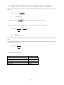
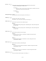
Samples for natural brightnesses EOB:
Illuminance
Sunlight, summer
Sunlight, winter
Street lighting
Workroom
Night with full moon
Inner rooms
EOB in [lx]
100000
10000
3...30
40...300
0,2
40...150
- page 7 -
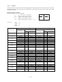
Reflection factors ρ for different materials:
Material, object
Wood, bright/dark
Concrete, bright/dark
Tar cover
Brick, bright/dark
Chromium, polished
statistical photografical standard subject
ρ
0,3...0,5/0,1...0,25
0,3...0,5/0,15...0,25
0,08...0,15
0,3...0,4/0,15...0,25
0,6...0,7
0,17
1.6 Relation between radiation-physical and light-technical figures
Light-technical figures take the physiological brightness sensitivity of the human eye into consideration, while
radiation-physical figures show the power aspect. To be able to convert on figure into the other one, the relative
spectral brightness sensitivity V(λ) of the human eye is required. The relation between beam power Le and
luminance L is:
780 nm
L = K max
Kmax
Le(λ)
V(λ)
∫ L (λ) ⋅ V(λ ) ⋅ dλ
e
λ =380 nm
photo-metrical radiadion equivalent 683 lm/W
spectral power density of radiation in interval (λ+dλ)
relative spectral brightness sensitivity of the human eye
λ
400nm
500nm
555nm
600nm
700nm
V(λ)
0,0004
0,323
1
0,631
0,0041
All calculations for calibrating the camera refer to monochromatic light with a wavelength of λ=555nm. The
function V(λ) reaches its maximum of V(555nm)=1 with this wavelength. As exception of the integral mentioned
above follows:
L = 683
lm
⋅ Le
W
The same goes for the intensity of brightness E and the irradiance Eet:
E = 683
lm
⋅ Ee
W
- page 8 -
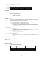
1.7 Calibration equation
The calibration equation gives the connection between the digitally changed numerical value Z and the luminance L when chosing aperture k.
The summing of the equations
E S = L OB ⋅
E S = 683
lx ⋅ m 2
π
⋅
2
cd
k
4
k0
τ
lm
⋅ E eS
W
E eS = E e 0 ⋅ 2
Conneciton subject luminance – sensor brightness
Connection radiation-physical and light-technical figures
Z
−16
32
Definition ADC-converting area
results in the calibration equation:
L OB
L0
2
Z
−16
1 k
= 683 ⋅
⋅ ⋅ 2 32
π ⋅ τ k0
L0 = 4cd/m2
k0 = 1
τ = 0,8
datum for luminance
datum for aperture
transmittance of the lens
LOB
Z
k
subject luminance in cd/m2
digital ADC numerical value
aperture
The calibration equation in logarithmic form:
L
k
683 Z
lb OB − 2lb − lb
= − 16
π ⋅ τ 32
L0
k0
- page 9 -
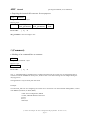
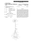
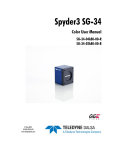
Calibration
equation
Kalibriergleichung
1,00E+11
k = 16
1,00E+10
k = 11
k=8
k = 5,6
k=4
1,00E+09
Sun
k = 2,8
k=2
k = 1,4
k=1
1,00E+08
Arc lamp
Wolfram filament
1,00E+07
L in cd/m
2
1,00E+06
1,00E+05
Summer sun, water
1,00E+04
Summer sun
Bright sun
Weak sun
1,00E+03
Sun, shadow
Dull winter day
1,00E+02
Lit shop window
1,00E+01
Stage lighting
Street lighting
Lit buildings
1,00E+00
1,00E-01
1,00E-02
0
128
256
384
512
640
768
896
1024
Z
Presentation of the calibration equation for apertures k=1 to 16
- page 10 -
1.8 Presentation of subjects with different brightnesses
When the subject luminance LOB in the logarithmic form of the calibration equation is replaced by the reflection
factor ρ and the subject brightness EOB this results in the following:
E
lb OB
E0
k
683 Z
+ lb (ρ ) − 2lb − lb
= − 16
τ 32
k0
E 0 = 4lx
When illuminating two subjects with reflection factors ρ1 and ρ2 in succession with two brightnessses EOB1 and
EOB2, the differences of the values Z are:
Difference of the numerical value ∆Z between subject with ρ1 and ρ2 and with brightness EOB1 and EOB2:
∆Z = Z(ρ1 ) − Z(ρ 2 ) = 32 ⋅ [lb (ρ1 ) − lb(ρ 2 )]
Brightness ratios because of different reflection factors ρ in the subject are given as constant number
differences ∆ Z, independent of the subject brightness.
1.9 Assessment of the range of gray scales in the logarithmically altered
frame – the photographic normal subject
According to statistical surveys the most often subjects have a contrast difference of 1:32 and an average
reflection factor of ρ = 0,17. These figures can be consulted when estimating the gray scales Z pictured with a
certain brightness.
Definition: photographic standard subject
L max
= 32
L min
ρ = 0,17
The average gray tone results from the above mentioned:
E
k
683
Z = 32 ⋅ lb OB + lb (0,17 ) − 2lb − lb
+ 16
τ
k0
E0
E
k
Z ≈ 32 ⋅ lb OB − 2lb + 118
k 0
E0
The difference between the biggest and the smallest gray tone is:
∆Z = Z max − Z min = 32 ⋅ lb (32) = 160
- page 11 -
2 The functional architecture of the camera LOGLUX
2.1 Survey of functions
The camera LOGLUX contains all analog and digital switching components necessary for a frame recording.
They can be splitted up into 3 groups:
Analog switching components
1.1 switching components for processing the frame signal (sensor, amplifier)
1.2 switching components for producing an auxiliary voltage
Digital switching components
2.1 switching components for a frame processing (data sorting, address generation)
2.2 switching components for transmitting frame signals (image data interface)
2.3 switching components for camera control (controller and periphery)
AD-, DA-converter
3.1 DA-converter for a digital control of the necessary auxiliary voltages
3.2 AD-converter for converting the image signals
All analog switching components have such a structure that they can be completely digitally balanced by a
configuration bus. The analog and digital components necessary for an image recording are controlled by a
16bit-microcontroller. The microcontroller contains all setting features and initializes all assemblies after
switching the camera on.
These features of the camera can be gained in different ways:
•
•
•
automatic identification when trimming the camera
by transfering instruction over the configuration interface
by setting the configuration switch on the camera back
The camera has a data interface for transfering the frame datas. This interface is removeable so that the
transmission medium and the way of transmission can easily be adjusted.
The functions of the most important components of the HDRC4-camera LOGLUX as well as their configuration is described in the following:
•
HDRC4 sensor
configuration and addressing requirements
•
VSG (Variable Scan Generator)
Register description and configuration instructions
•
Data sorting
Description of the data sorting depending on the mode
•
DA-converter for producing an auxiliary voltage
Register description
- page 12 -
2.2 Frame data interface of the camera LOGLUX
2.2.1 Description of the interface
Different interface modules can be attached to the camera LOGLUX:
• Data transmission via cable, parallel
• LWL-data transmission, serial
The parallel data interface is available in two different variants:
1. LVDS (Low Voltage Differential Signaling) - level
2. RS422 - level
Both interfaces only differ from each other in their pegel definition but not in the structure of their transmission
protocols. These interface standards are symmetric data signals which means that every signal is transmitted
once inverted (identification: -) and once not-inverted (identification: +). An incorrect data transmission by
compensating streams in the signal groundings (application in industrial plants) can thus be avoided.
Bundles of twisted pair two-wire circuits with a characteristic impedance of Z=100Ω are used as data cables. For
this reason all data receivers require a terminator of R=100Ω.
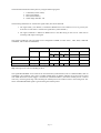
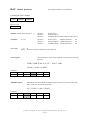
Comparision RS422, LVDS (with RL=100Ω , typ.):
Sum of the potential difference between negated and unnegated exit:
∆U O = U OH − U OL
LVDS
335mV
RS422 (3,3V)
2,6V
Offset voltage (Common Mode Voltage):
U CM =
U OH + U OL
2
LVDS
1,25V
RS422 (3,3V)
1,5V
Power demand per signal, at Ub=3,3V:
PV =
LVDS
11,0mW
U b ⋅ ∆U O
RL
RS422
85,8mW
Power demand when using all 13 signals (10 data bits, LEN, FEN, CAMCLK):
143mW
1,1W
- page 13 -
The frame data transmission takes place by using the following signals:
1.
2.
3.
4.
CAMCLK (Camera Clock)
LEN (Line Enable)
FEN (Frame Enable)
10 Bit image datas D0 - D9
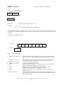
The following definitions are valid for the signals LEN, FEN and CAMCLK:
1. The signal LEN („Line Enable“) is defined as HIGH active if the readout of a row is given by the
level LEN=H. The same is valid for the signal FEN („Frame Enable“).
2. The signal CAMCLK is defined as HIGH active if the datas being on the exit are valid with an
increasing (LH) edge of the signal.
The signals CAMCLK, LEN and FEN can be configured as HIGH or LOW active ( LEN, FEN, CAMCLK
commands, refer to tabel of commands).
CAMCLK
LEN
FEN
HIGH active LOW active HIGH active LOW active HIGH active LOW active
lof=0
lof=1
lof=0
lof=1
Image datas valid
↑ edge
↓ edge
H
L
H
L
Line enable
↑ edge
↓ edge
L
H
H
L
Frame Enable
↑ edge
↓ edge
L
H
X
L
X
H
Tip: meaning lof-bit, refer to VSG-Reg. 0, Bit 8
The signal FRAMETRIG can be used for the external frame synchronization (refer to command TRIG, table of
commands). The symmetric entry selects a LVDS- (DS90LV032) or RS422- (DS26LV32) receiver and is closed
with 100Ω. When the external trigger is switched on (command: TRIG 1) the frame readout process is started
with every increasing (LH) edge. After finishing the readout process the camera returns to the waiting state. The
status of the FRAMETRIG signal is ignored during the readout process.
- page 14 -
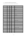
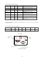
2.2.2 Pin-load of the LOGLUX frame data interface
The frame data interface is located on the camera back. (44-pole. D-SUB jack)
Designation
PIN no.
Quty.
Input, Output
Description
D0+
1
1
A
Data bit 0
D1+
2
1
A
Data bit 1
D2+
3
1
A
Data bit 2
D3+
4
1
A
Data bit 3
D4+
5
1
A
Data bit 4
D5+
6
1
A
Data bit 5
D6+
7
1
A
Data bit 6
D7+
8
1
A
Data bit 7
D8+
9
1
A
Data bit 8
D9+
10
1
A
Data bit 9
LEN+
11
1
A
Line Enable
FEN+
12
1
A
Frame Enable
CAMCLK+
13
1
A
Camera Clock
FRAMETRIG+
15
1
E
Frame Trigger
D0-
16
1
A
Data bit 0, negated
D1-
17
1
A
Data bit 1, negated
D2-
18
1
A
Data bit 2, negated
D3-
19
1
A
Data bit 3, negated
D4-
20
1
A
Data bit 4, negated
D5-
21
1
A
Data bit 5, negated
D6-
22
1
A
Data bit 6, negated
D7-
23
1
A
Data bit 7, negated
D8-
24
1
A
Data bit 8, negated
D9-
25
1
A
Data bit 9, negated
LEN-
26
1
A
Line Enable, negated
FEN-
27
1
A
Frame Enable, negated
CAMCLK-
28
1
A
Camera Clock, negated
FRAMETRIG-
30
1
E
Frame Trigger, negated
SDA
31
1
E/A
Datas, I2C-bus (optional)
SCL
32
1
E
Clock, I2C-Bus (optional)
GND
33-40
4
VCC3
41, 42
2
A
3,3V
VCC5
43, 44
2
A
5V
Ground
- page 15 -
2.2.3 Cable plan, LOGLUX frame data interface (feeder cable)
Twisted pair cable, Z≈100Ω, 20 line pairs + screen
2×44-pole D-SUB jack with plug shell
Designation
D0
D1
D2
D3
D4
D5
D6
D7
D8
D9
LEN
FEN
CAMCLK
OTR
FRAMETRIG
GND1
GND2
GND3
+3,3V
+5V
SCHIRM
jack 1, 44-pole D-SUB
Pair no.
Pin no.
1
1
16
2
2
17
3
3
18
4
4
19
5
5
20
6
6
21
7
7
22
8
8
23
9
9
24
10
10
25
11
11
26
12
12
27
13
13
28
14
14
29
15
15
30
16
31
32
17
33
34
18
35
36
19
41
42
20
43
44
Housing
jack 2, 44-pole D-SUB
Pair no.
Pin no.
1
1
16
2
2
17
3
3
18
4
4
19
5
5
20
6
6
21
7
7
22
8
8
23
9
9
24
10
10
25
11
11
26
12
12
27
13
13
28
14
14
29
15
15
30
16
31
32
17
33
34
18
35
36
19
41
42
20
43
44
-
- page 16 -
2.3 Description of functions: HDRC4-Sensor
The HDRC4-sensor combines on one chip two light-sensitive CMOS-arrays with column and line stucture.
Every array has an organisation of 256×256 pixel. The corresponding column and row addresses of both halfs of
the sensor are connected. The selection of two pixels (right/left half of the sensor) is possible in different ways.
The selection of the access rule is determined by the single bits of the HDRC-register (refer to command HDRC
par as well). The selection of the half of the sensor is carried out by an additional address bit. This bit selects the
seperately digital changed frame information of the left/right half of the sensor via a data multiplexer.
Consequently, the address clock frequency can always be half of the pixel clock frequency and two corresponding pixel are read out with one access cycle.
To avoid failures of the analog circuit components caused by the digital components, an addressing in GRAY
code is possible. The selection of GRAY or BINARY addressing is determined for both halfs of the senor.
The access rule of the line and column decoder can be selected by an assigned mirror bit:
1.
2.
mirror-bit =0: created column/row address X selects column Spalte X or row X
mirror-Bit =1: created column/row address X selects column or row (255-X)
Please note that the mirroring results from a subtraction and not from forming the ones complement because this
would lead to a malfunction when having chosen the GRAY addressing.
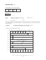
Determination of the addressing by the HDRC-register:
Bit
HDRC-Reg.
7
lrm
6
5
4
3
2
1
0
gray
Rowlm
collm
rowrm
colrm
• colrm, column right mirror: By activating this bit the right-hand half of the sensor can be mirrored around
the north-south axis. When addressing column N, column (255-N) is read out.
• rowrm, row right mirror:
By activating this bit the right-hand half of the sensor can be mirrored around
the east-west axis. When addressing line N, line (255-N) is read out.
• collm, column left mirror:
as colrm, left-hand half of the sensor
• rowlm, row left mirror:
as rowrm, left-hand half of the sensor
• gray:
Selection of the addressing code, =0 binary code/ =1 gray code.
• lrm, left right mirror: By activating this bit the addressing of the sensor halfs is interchanged. (When
addressing the left-hand half of the sensor, the right-hand half of the sensor is read out and inverted.)
The activating of these bits is independently done by the camera internal control software when using the
following commands:
1.
2.
3.
4.
Selection readout mode, MODE-command
Mirroring the image, MIR-command
Rotating the image, ROT-command
(initialization of the camera after the switching on)
- page 17 -
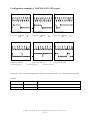
Examples, pixel adressing:
The following examples show the pixel addressing depending on the mirror-bits. The sensor provides one pixel
formation for the right and left-hand half of the sensor each. All examples are valid for a row address y = 80 and
a column address x = 60.
x=60
x=316
collm =0
rowlm =0
y=80
y=80
colrm =0
rowrm =0
x=451
x=60
y=80
y=80
collm =0
rowlm =0
colrm =1, column right mirrored
rowrm =0
x=195
x=316
collm =1, column left mirrored
rowlm =0
y=80
y=80
colrm =0
rowrm =0
x=60
x=316
collm =0
rowlm =0
colrm =0
rowrm =1, row right mirrored
y=80
y=175
x=451
x=60
collm =0
rowlm =1, row left mirrored
colrm =1, column right mirrored
rowrm =1, row right mirrored
y=175
y=175
- page 18 -
2.4 Description of functions: VSG (Variable Scan Generator)
VSG is a programmable address generator. It provides the address, control and synchronous signals required for
reading out the sensor:
1.
2.
3.
addresses of rows and columns
LEN- , FEN-, CAMCLK-signal for frame data transfer
Control signals, reading and writing addresses for data sorting
2.4.1 Generation of the column and row addresses
There are two different ways possible for reading out the sensor:
Single channel mode (Mode 0)
The frame information of two pixels is gained in every addressing cycle. However, the information of one pixel is warped afterwards. The order of the pixel coordinates read out of the
sensor corresponds to the order of the image datas given out.
Dual channel mode (Mode 2,3)
The image information of two pixels is gained in every addressing cycle. The order of the pixel
coordinates read out of the sensor does not correspond to the order of the image datas given
out. Therefore an image data sorting is absolutely necessary.
2.4.2 The column and row address counter
VSG contains a 9bit-column and an 8bit-row counter. Start and offset constants of the counter are programmable
over register.
The X/Y_BASE-register contains the start constants of the respective counter. The resetting is carried out after
reaching the count (X/Y_BASE) + (X/Y_OFFSET).
Example:
X_BASE = 100, X_OFFSET = 100
Capacity of the column counter: 100...200 (101 columns!)
X_BASE = 100, X_OFFSET = 100
Capacity of the row counter: 0...255 (256 rows!)
Whole image area:
X_BASE = 0, X_OFFSET = 511
Y_BASE = 0, Y_OFFSET = 255
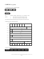
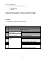
Table, VSG-register 4...7:
Bit
VSG-Reg. 4
VSG-Reg. 5
VSG-Reg. 6
VSG-Reg. 7
8
7
6
5
4
3
2
x_base (column start constant)
y_base (row start constant)
x_offset (column offset constant)
y_offset (row offset constant)
- page 19 -
1
0
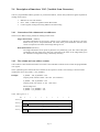
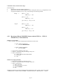
2.4.3 Configuration of X/Y_BASE and X/Y_OFFSET-register
2.4.3.1
MODE 0 (single channel mode)
In readout mode 0 the position and size of the frame which is to read out can be selected completely free. The
coordinates of the top left-hand frame corner are determined by the X/Y_BASE-register pair, the size of the
frame by the X/Y_OFFSET-register pair.
X_OFFSET
X_BASE
[0,0]
Y_BASE
Frame which is to
read out
Y_OFFSET
[511,255]
Configuration of the mirror-bits for an upright non-reverse image:
colrm
rowrm
collm
rowlm
2.4.3.2
=0
=0
=0
=0
MODE 2 (dual channel mode, converging)
The left-hand sensor half is exclusively addressed in dual channel mode. Corresponding pixel of the right-hand
half are read out parallel and afterwards correctly sorted in the image data stream. To get an converging readout,
the columns of the right-hand sensor half needs to be mirrored.
Configuration of the mirror-bits for an upright and non-reserve image:
colrm
rowrm
collm
rowlm
=1
=0
=0
=0
columns right mirrored
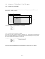
The following sketches show the difference between the addressed and read out sensor area in MODE 2.
- page 20 -
Addressed sensor area:
X_OFFSET
X_BASE
[0,0]
Y_BASE
Addressed
sensor area
Y_OFFSET
X
Y
[511,255]
Secondary requirement in MODE 2: [X_BASE] + [X_OFFSET] = 255
Read out sensor area:
X_BASE
nd
2×X_OFFSET
[0,0]
Y_BASE
Read out image area
Addr.
direction
left-hand
X
X
Addr.
Direction
right-hand
Y
Y_OFFSET
Y
[511,255]
2.4.3.3
MODE 3 (dual channel mode, divergent)
The left sensor half is exclusively addressed in the dual channel mode. Corresponding pixel of the right-hand
half are read out parallel and afterwards correctly sorted in the image data stream. To obtain a divergent readout,
the columns of the left-hand sensor half have to be mirrored.
Configuration of the mirror-bits for an upright and non-reverse image:
colrm
rowrm
collm
rowlm
=0
=0
=1
=0
columns left mirrored
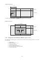
The following sketches show the difference between the addressed and read out sensor area in MODE 3.
- page 21 -
Addressed sensor area:
X_OFFSET
[0,0]
Y_BASE
Addressed
sensor area
Addr.
direction
X
Y_OFFSET
Y
[511,255]
[511,255]
Secondary requirement, MODE 3: X_BASE = 0
Read out sensor area:
2×X_OFFSET
[0,0]
Y_BASE
Read out image area
X
Addr.
direction
left-hand
Y
Addr.
direction
X
Y_OFFSET
Y
[511,255]
2.4.4 Configuration of the MODE and PREDIV-registers (VSG-Reg. 0,1)
By configuring the MODE-registers, the readout mode and further essential working parameters of the camera
are determined:
•
•
•
•
•
•
•
Readout mode
Pixel clock frequency ( fcamclk)‘
Single step operating
External image triggering
Selection: binary/gray addressing
OR-concatenation of the synchronous signals
System-internal settings
- page 22 -
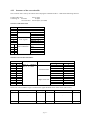
Table: MODE and PREDIV-register (VSG-reg. 0,1)
Bit
8
7
6
5
4
3
VSG-Reg. 0
lof
sa
Step
ext_trig
gray
delay
VSG-Reg. 1
2
1
0
mode
prediv
Description:
mode (Reg. 0, Bit 0,1,2)
The mode-bits determine the readout mode. Only three of all eight possible variants are useful
for the programmer (MODE 0,2,3).
MODE 0: mode = 000b
MODE 2: mode = 010b
MODE 3: mode = 011b
delay (Reg. 0, Bit 3)
The delay-bit controls the moment of the row and column address change. It is set by the
camera-internal software to 1 and should not be changed.
gray (Reg. 0, bit 4)
=1 row and column addresses are generated in the gray code.
=0 row and column addresses are generated in the binary code.
In order to ensure a correct sensor addressing, the figure of the gray bits has to correspond with the gray bit of the HDRC-registers. The camera-internal software mainly
operates with gray addressing (gray = 1).
trig (Reg. 0, bit 5)
=1 single frame mode
A LH single edge on the external triggering entry starts one readout of the sensor with
the current X/Y_OFFSET and X/Y_BASE-parameters.
=0 running frame mode
The sensor is continuously read out.
step (Reg. 0, bit 6)
=1 single step operation
The single step operation can only temporary be used by the camera-internal functions.
sa (Reg. 0, bit 7)
camera-internal functions
lof (Reg. 0, bit 8)
=0 The LEN signal is switched „inactive“ during the row synchronization phase.
=1 The LEN signal is switched „inactive“ during the row or frame synchronization phase
(len or fen)
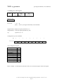
prediv (Reg. 1, bit 0,1)
predivider setting for frame data clock
Prediv
00b
01b
10b
11b
fCAMCLK, MODE 0
8MHz
4MHz
2MHz
1MHz
- page 23 -
fCAMCLK, MODE 2,3
16MHz
8MHz
4MHz
2MHz
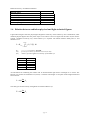
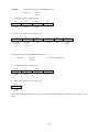
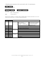
2.4.5 PIPELINE-DELAY register (VSG reg. 8)
Pipeline-ADC are used for the frame data conversion in LOGLUX cameras. What makes these AD-converter
stand out are their low power consumption. The AD conversion is carried out by the operating principle above
mentioned in several steps. 2bit information are obtained during every step in this case. A temporal shift of 5
clocks (with 10bit ADC-resolution) between the analog input figure and the converted digital word on the data
exit results from this. The sketch shown below gives the architecture of such a cascade transformer in principles.
Analog
IN
Sample & Hold
Sample & Hold
+
-
ADC
+
×4
×4
-
DAC
ADC
2bit
DAC
ADC
2bit
2bit
Digital OUT
In order to balance the temporal shift between the sensor addressing and the data sorting, the PIPELINE_
DELAY register has to be loaded with a circuit-specific constant:
PIPELINE_DELAY = [number of clocks required for the conversion]-2
The figure for the PIPELINE_DELAY-register is for the camera LOGLUX =5 and must not be changed by the
user because this figure is a system constant.
PIPELINE_DELAY = 3
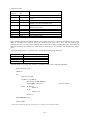
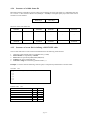
2.4.6 Configuration of the frame data transmission control protocol by the LEN, FEN
and MEASURE register
Table: LEN, FEN and MEASURE-register
Bit
8
7
6
5
4
2
1
0
clkinv
clkoff
pxlclk
adcclk
len
VSG-Reg. 2
VSG-Reg. 3
VSG-Reg. 9
3
fen
chaninv
feninv
leninv
len (Reg. 2, bit 0...7)
• Length of the inactive phase of the LEN-signal with row synchronization
Length of the LEN-signal in number L CAMCLK-clocks
MODE 0:
MODE 2,3:
L=[len]
L=2×
×[len]
- page 24 -
fen (Reg. 3, bit 0...7)
• Length of the inactive phase of the FEN-signal with frame synchronization
Lenght of the FEN-signal in number Z rows
For [fen]=0:
During the frame synchronization the FEN-signal is in addition to the LENsignal inactive for the same period of time.
For [fen]≠0:
Z=[fen]
adcclk, pxlclk (Reg. 9, bit 0,1)
• Switching off the internal clock signals, set bits always =0
clkoff (Reg. 9, bit 2)
• Switching off the frame clock CAMCLK
This function is only used camera-internally, set bit always =0
clkinv (Reg.9, bit 3)
• Determination of polarity of the CAMCLK-signal
clkinv=0:
frame datas with LH signal edge of the CAMCLK-signal is valid, data change with
HL single edge
clkinv=1:
frame datas with HL single edge of the CAMCLK-signal is valid, data change with
LH single edge
leninv (Reg.9, bit 4)
• Determination of polarity of the LEN-signal
leninv=0:
LEN-signal with running row transmission =HIGH, LEN-signal with row
synchronization =LOW
leninv=1:
LEN-signal with running row transmission =LOW, LEN-signal with row
synchronization =HIGH
feninv (Reg.9, bit 5)
• Determination of polaritiy of the FEN-signal
feninv=0:
FEN-signal with running frame transimission =HIGH, LEN-signal with frame
synchronization =LOW
feninv=1:
FEN-signal with running row transmission =LOW, FEN-signal with frame
synchronization =HIGH
chaninv (Reg.9, bit 7)
• Inversion of channel selection signal, set bit always =0
- page 25 -
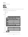
2.5 Frame data sorting
The frame data sorting is carried out by a Dual-Port-RAM 1k×10bit (2 rows×512× 10bit). One port is
exclusively used for reading, the other one exclusively for writing. Now VSG provides the sorting addresses in
this way that the frame datas read out on the writing port are straight-line written in chronological order and the
frame datas of the previous row are straight-line read out in local order on the reading port. Consequently, a time
shift of one row can be found between the frame data output and current readout coordinates of the sensor.
2.5.1 Frame data sorting in single channel mode (MODE 0)
When the single channel mode is set, one pixel is read during every addressing cycle. A data sorting is not
necessary. However, it is carried out because of circuit-technical reasons. In single channel mode the right half
of the sensor is analyzed with a column address ≥256, the left half with a column address <256. The information
of the corresponding pixel on the respectively other half of the sensor is rejected. Consequently, a completely
free predefinition of the frame which is to read out is possible. However, the maximum pixel clock frequency
must not be higher than 8MHz.
The data sorter works from the assumption that the frame datas which need to be sorted are read out sequentially
with a rising row and column address.
The frame data sorting is carried out in a simple way:
Sensor access
n
n+1
n+2
n+3
n+4
...
m
m+1
m+2
m+3
m+4
...
Dual-Port-RAM, writing port
Dual-Port-RAM
Pixel information
Coordinate[X,Y]
Bank Writing address
...
...
...
[ x ,y]
0
Adr
[x+1,y]
0
Adr+1
[x+2,y]
0
Adr+2
[x+3,y]
0
Adr+3
[x+4,y]
0
Adr+4
...
...
...
[ x ,y+1]
1
Adr
[x+1,y+1]
1
Adr+1
[x+2,y+1]
1
Adr+2
[x+3,y+1]
1
Adr+3
[x+4,y+1]
1
Adr+4
...
...
...
Dual-Port-RAM, reading port
Dual-Port-RAM
Pixel information
coordinate[X,Y]
Bank Reading address
...
...
...
[ x ,y-1]
1
Adr
[x+1,y-1]
1
Adr+1
[x+2,y-1]
1
Adr+2
[x+3,y-1]
1
Adr+3
[x+4,y-1]
1
Adr+4
...
...
...
[ x ,y]
0
Adr
[x+1,y]
0
Adr+1
[x+2,y]
0
Adr+2
[x+3,y]
0
Adr+3
[x+4,y]
0
Adr+4
...
...
...
2.5.2 Frame data sorting in dual channel mode (MODE 2,3)
Two corresponding pixel are read in one access cycle in the dual channel mode. MODE 2 and MODE 3 differ
from each other only in their sorting algorithm by the interpretation of the coordinates of the sequentially read
frame datas.
- page 26 -
2.5.2.1
MODE 2:
The frame datas are sorted in this way that the frame datas are sorted locally correct when being convergingly
read out. Converged means in this case that corresponding pixel pairs draw nearer to each other during the
readout process.
Example, converging readout:
Pixel coordinates in one cycle, full frame:
n:
{[ x,y] , [511x,y]}
n+1:
{[x+1,y] , [511-(x+1),y]}
n+2:
{[x+2,y] , [511-(x+2),y]}
n+3:
{[x+3,y] , [511-(x+3),y]}
n+4:
{[x+4,y] , [511-(x+4),y]}
mirror-bits:
colrm
rowrm
collm
rowlm
Sensor access
n
n+1
n+2
n+3
n+4
n+126
n+127
n+128
n+129
n+130
...
n+255
n+256
...
etc.
=1
=0
=0
=0
Dual-Port-RAM, writing port
Dual-Port-RAM
Pixel information
coordinate[X,Y]
Bank Writing address
Dual-Port-RAM, reading port
Dual-Port-RAM
Pixel information
Coordinate[X,Y]
Bank Reading address
...
...
...
...
...
...
[ 0,y]
[511,y]
[ 1,y]
[510,y]
[ 2,y]
[509,y]
[ 3,y]
[508,y]
[ 4,y]
[507,y]
0
0
0
0
0
0
0
0
0
0
0x000
0x001
0x002
0x003
0x004
0x005
0x006
0x007
0x008
0x009
[0,y-1]
[1,y-1]
[2,y-1]
[3,y-1]
[4,y-1]
[5,y-1]
[6,y-1]
[7,y-1]
[8,y-1]
[9,y-1]
1
1
1
1
1
1
1
1
1
1
0x000
0x002
0x004
0x006
0x008
0x00A
0x00C
0x00E
0x010
0x012
...
...
...
...
...
...
[126,y]
[385,y]
[127,y]
[384,y]
[128,y]
[383,y]
[129,y]
[382,y]
[130,y]
[381,y]
0
0
0
0
0
0
0
0
0
0
0x0FC
0x0FD
0x0FE
0x0FF
0x100
0x101
0x102
0x103
0x104
0x105
[252,y-1]
[253,y-1]
[254,y-1]
[255,y-1]
[256,y-1]
[257,y-1]
[258,y-1]
[259,y-1]
[260,y-1]
[261,y-1]
1
1
1
1
1
1
1
1
1
1
0x1F8
0x1FA
0x1FC
0x1FE
0x1FF
0x1FD
0x1FB
0x1F9
0x1F7
0x1F5
...
...
...
...
...
...
[255,y]
[511,y]
[255,y+1]
[256,y+1]
0
0
1
1
0x1FE
0x1FF
0x000
0x001
[510,y-1]
[511,y-1]
[0,y]
[1,y]
1
1
0
0
0x003
0x001
0x000
0x002
...
1
...
...
0
...
- page 27 -
2.5.2.2
MODE 3:
The frame datas are sorted in this way that frame datas are sorted locally correct when the sensor is read out
divergently. Divergent means here that corresponding pixel pairs approach to the respective edge of the frame
when being read out.
Example, divergent readout:
Pixel coordinates in one cycle, full frame:
n:
{[
255-x,y] , [
256+x,y]}
n+1:
{[255-(x+1),y] , [256+(x+1),y]}
n+2:
{[255-(x+2),y] , [256+(x+2),y]}
n+3:
{[255-(x+3),y] , [256+(x+3),y]}
n+4:
{[255-(x+4),y] , [256+(x+4),y]}
mirror-bits:
colrm
rowrm
collm
rowlm
Sensor access
n
n+1
n+2
n+3
n+4
n+126
n+127
n+128
n+129
n+130
...
n+255
n+256
...
u.s.w
=0
=0
=1
=0
Dual-Port-RAM, writing port
Dual-Port-RAM
Pixel information
coordinate[X,Y]
Bank Writing address
Dual-Port-RAM, reading port
Dual-Port-RAM
Pixel information
coordinate[X,Y]
Bank Reading address
...
...
...
...
...
...
[255,y]
[256,y]
[254,y]
[257,y]
[253,y]
[258,y]
[252,y]
[259,y]
[251,y]
[260,y]
0
0
0
0
0
0
0
0
0
0
0x000
0x001
0x002
0x003
0x004
0x005
0x006
0x007
0x008
0x009
[0,y-1]
[1,y-1]
[2,y-1]
[3,y-1]
[4,y-1]
[5,y-1]
[6,y-1]
[7,y-1]
[8,y-1]
[9,y-1]
1
1
1
1
1
1
1
1
1
1
0x1FE
0x1FC
0x1FA
0x1F8
0x1F6
0x1F4
0x1F2
0x1F0
0x1EE
0x1EC
...
...
...
...
...
...
[129,y]
[382,y]
[128,y]
[383,y]
[127,y]
[384,y]
[126,y]
[385,y]
[125,y]
[386,y]
0
0
0
0
0
0
0
0
0
0
0x0FC
0x0FD
0x0FE
0x0FF
0x100
0x101
0x102
0x103
0x104
0x105
[252,y-1]
[253,y-1]
[254,y-1]
[255,y-1]
[256,y-1]
[257,y-1]
[258,y-1]
[259,y-1]
[260,y-1]
[261,y-1]
1
1
1
1
1
1
1
1
1
1
0x006
0x004
0x002
0x000
0x001
0x003
0x005
0x007
0x009
0x00B
...
...
...
...
...
...
[ 0,y]
[511,y]
[255,y+1]
[256,y+1]
0
0
1
1
0x1FE
0x1FF
0x000
0x001
[510,y-1]
[511,y-1]
[0,y]
[1,y]
1
1
0
0
0x1FD
0x1FF
0x1FE
0x1FC
...
1
...
...
0
...
- page 28 -
3 Configuration of the camera LOGLUX
3.1 Introduction
The device-internal camera control makes it possible to set the following parameters over the configuration
interface:
•
•
•
•
•
•
•
frequency and polarity of the camera clock CAMCLK
pulse width and polarity of the row synchronuous signal LEN (Line Enable)
pulse width and polarity of the row synchronuous signal FEN (Frame Enable)
size and position of sensor half which is to read out
readout mode
infensification and offset of the video amplifier
selection of the correction table
In order to make the camera configuration easier for the user, the internal software offers two opportunities:
1. ASCII (plain text) control
2. HEX control
The selection of the way of controlling and of the interface-specific parameter is effected by the configuration
switch on the camera back.
LOGLUX cameras have a RS232C (V.24) configuration interface as standard. All parameters declared are not
erased when switching the camera off and are automatically set when switching the camera on or when pressing
the RESET button. It is, therefore, possible to use the camera independently of a configuration computer or to do
the configuration only when installing the camera.
Requirements for the camera configuration:
1. Configuration computer with serial interface (e.g. COM1, PC)
2. VT100 terminal or special configuration software
3. 1 zero modem cable
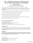
3.2 RS232C Configuration interface
The camera-internal RS232C interface is equipped with an IC MAX3232 and attends the signals TxD, RxD,
CTS and RTS. The signals DTR, DSR and DCD are internally connected. For controlling the data transmission
the hardware (RTS/CTS) control protocol is applied. The transmission rate, the number of stop bits and data bits
as well as the parity bit can be selected with the configuration switch (see below). At the same time it is possible
to define the interface parameters completely free or from a default selection.
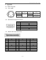
The 9-pole D-SUBm plug located on the camera back has the following pin assignments:
- page 29 -
RS232 connection, 9-pole D-SUB plug
Designation
/DCD
PIN #‚
1
Quantity
1
Input/Output
E
2
3
4
1
1
1
E
A
A
GND
/DSR
5
6
1
1
E
/RTS
7
1
A
Description
DATA CARRIER DETECTED
with /DTR and /DSR connected
Receive datas
Transmission datas
DATA TERMINAL READY
with /DCD and /DSR connected
GROUND
DATA SET READY
with /DCD and /DTR connected
REQUEST TO SEND
RxD
TxD
/DTR
/CTS
8
1
E
CLEAR TO SEND
RI
9
1
E
RING INDICATOR
Not connected
A cable (zero modem cable) with the connections mentioned below is necessary to connect the camera with the
configuration computer.
List of connections for the zero modem cable
Jack 1
9-pole D-SUBw
Jack 2
9-pole D-SUBw
RxD
PIN 2
TxD
PIN 3
TxD
PIN 3
RxD
PIN 2
RTS
PIN 7
CTS
PIN 8
CTS
PIN 8
RTS
PIN 7
DTR-DCD
PIN 4-1
DSR
PIN 6
DSR
PIN 6
DTR-DCD
PIN 4-1
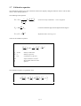
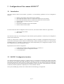
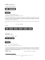
LWL interface
configuration
switch
Power
supply
9
1
Reset button
6
5
Configuration interface
back side of the camera
- page 30 -
GND
PIN 5
GND
PIN 5
3.3 RS422 Configuration interface (optionally)
The configuration interface can optionally be equipped with a RS422 driver (MAX3488). The interface operates
without a hardware control protocol in this case (only RxD+, RxD-, TxD+, TxD-). The D-Sub plug was wired in
this way that a zero modem cable of a RS232C interface can further be used for communication.
To make a data transmission over longer distances possible, the symmetric data input (RxD+, RxD-) is closed
with a terminator of R = 100Ω.
RS422 connection, 9-pole D-SUB jack
Designation
RxD+
TxD+
GND
RxDTxD-
PIN #
1
2
3
4
5
6
7
8
9
Quantity
1
1
1
1
1
1
1
1
1
Input/Output
I
O
I
O
Description
Connected with PIN 4,6
Receive datas
Transmission datas
Connected with PIN 1,6
GROUND
Connected with PIN 4,1
Receive datas, inverted
Transmission datas, inverted
Free
3.4 Signal-LED
The signal-LED on the camera back gives information about the present operating condition of the camera. The
following signals are assigned to different conditions:
Signal
Green continuous light
Green continuous light, short yellow blinking (0,5Hz)
Green flashing light
Yellow flashing light, slowly
Yellow flashing light, quickly
Yellow/red flashing light
Yellow/green flashing light
Green/red flashing light
Operating condition
camera operates, commands cannot be received
(configuration switch position 15)
camera operates, commands can be received
(configuration switch position 0...14)
camera carries out the command or is in the base
initialization after the switching on
Camera trimming
Flash-ROM is programmed
camera requests during the trimming routine a high
luminance
camera requests during the trimming routine a low
luminance
Base initialization after the WATCHDOG reset
- page 31 -
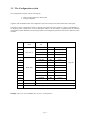
3.5 The Configuration switch
The configuration switch is used for selecting the
1. kind of control (plain text, HEX mode)
2. interface parameter.
Together with the RESET button the configuration switch is located on the camera back under a base plate.
The position of the configuration switch is enquired when powering up the operating voltage or after RESET i.e.
an adjusting under running does not have immediate influence. If the camera is equipped with the standard
configuration switch (RS232C), the following interface and configuration parameter arise for the different switch
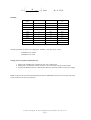
positions:
Position
Configuration
Transmission
mode
rate
Datas
0
1200 Bd
8 Bit
No parity
1
1200 Bd
7 Bit
No parity
9600 Bd
8 Bit
No parity
3
9600 Bd
7 Bit
No parity
4
1200 Bd
8 Bit
No parity
5
1200 Bd
8 Bit
Even
6
1200 Bd
8 Bit
Uneven
7
9600 Bd
8 Bit
No parity
9600 Bd
8 Bit
Even
9
9600 Bd
8 Bit
Uneven
10
19200 Bd
8 Bit
No parity
11
19200 Bd
8 Bit
Even
12
19200 Bd
8 Bit
Uneven
2
8
Plain text m.
HEX mode
13
Plain text m.
User-defined
14
HEX mode
User-defined
15
No external configuration (conf. Interface is not initialized)
Example: plain text control 9600Bd, 8bit, no parity: switch position
- page 32 -
1 Stop bit
3.6 Camera control in ASCII (plain text) mode
If the configuration switch is in setting 0...3 or 13, the camera can be configured in plain text. The camera has to
be connected to a VT100 compatible terminal for this (TERMINAL WIN3.1x, HYPER TERMINAL WIN95,
TERMINAL VT100 Norton Commander) and the terminal software needs to be configured as follows:
•
•
•
•
Transmission rate, 7/8 bit, parity, stop bit → see table, configuration switch
Hardware control protocol (RTS/CTS)
No local echo
Function keys for Windows OFF!
All commands are input in plain text. The data sender (keyboard) operates independently of the receiver because
the camera transmits a character echo itself. Small letters are automatically shifted into capital letters. All
printable ASCII characters (0x20...0x7F) are analyzed as well as the following control characters and ESCAPE
series:
^M
ESC O P
ESC O Q
ESC O P
ESC O Q
ESC [ A
ESC [ B
ESC [ C
ESC [ D
0x0D (carriage return, CR)
0x1B / 0x4F / 0x50
0x1B / 0x4F / 0x51
0x1B / 0x4F / 0x52
0x1B / 0x4F / 0x53
0x1B / 0x5B / 0x41
0x1B / 0x5B / 0x42
0x1B / 0x5B / 0x43
0x1B / 0x5B / 0x44
RETURN button
F1 button
F2 button
F3 button
F4 button
↑ button
↓ button
→ button
←-Taste
The data receiver (display) must be able to process the control characters given below in addition to all printable
ASCII characters (0x20...0x7F):
^M
^H
^J
^G
0x0D
0x08
0x0A
0x07
(carriage return, CR)
(back space, BS)
(line feed, LF)
(bell, BEL)
Cursor to the beginning of the line
Cursor one character to the left
Cursor one character downwards
Acoustic signal
Layout of function keys:
F1:
F2:
F3:
F4:
BACKUP,
Saving the present configuration
UNDO,
Setting of the configuration saved
Display of the configuration
Single frame statistics
Commands and parameters are seperated by blanks, parameters from each other by a comma:
COMMAND [parameter1 [, parameter2]]
Example:
CAMCLK 16,0
- page 33 -
When using the terminal function „SEND TEXT FILE“, it is possible to send command groups (e.g. setting for
certain types of framegrabbers). The file which is to be sent can be created with any editor (e.g. EDIT, WRITE).
Example: Setting of the camera clock signal for ELTEC framegrabber PCEye with CAMA 160:
// configuration ELTEC framegrabber
len 16,0
fen 0,0
// pixel clock 4MHz
camclk 4,0
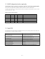
3.7 Camera control in HEX mode
Is the configuration switch in setting 4...12 or 14, the camera can be configured in plain text mode. This mode
permits the control with a minimum of characters transmitted. Every command has a capacity of 4 byte
maximum. That is why, the configuration interface has to be programmed to a transmission of 8-bit data
capacity. Furthermore, it is possible to transmit command sequences as datagrams which are sequentially
processed.
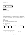
A datagram (command sequence) has always the following structure:
Byte 0
Byte 1
Byte 2
Byte 3
Byte n-1
Byte n
(Sequence length n)
date 1
date 2
date 3
date n-1
data n
Byte 0 includes the length of the command sequence. (An empty sequence has the sequence length 0)
Structure of an command:
1 byte command
Command code
2 byte command
Command code
Date 1
3 byte command
Command code
Date 1
Date 2
4 byte command
Command code
Date 1
Date 2
Date 3
The length of the instruction results from the command code. Is an command or an command sequence processed, a return data sequence consisting of 1 byte minimum (only error code) is produced. Is an command
sequence processed, the following command of this sequence is only then obeyed if this command produces the
error code 0x00 (ok). In case of an error the process is interrupted and the error code is sent to the control
computer via the configuration interface.
- page 34 -
Table: Error codes
Error code
Decimal
0
1...127
Hex.
0x00
0x01...0x7F
Description
128
249
0x80
0xF9
250
0xFA
251
252
253
254
255
0xFB
0xFC
0xFD
0xFE
0xFF
Command is properly obeyed
Marking byte, m data bytes follow (see table
below)
Command sequence too long
Set frame format or frame position cannot be
adjusted in the selected readout mode
Set pixel clock frequency cannot be adjusted in the
selected readout mode
Parameter is illegal in the selected readout mode
Priviliged command, see $ command
Illegal parameter
Number of parameters too small
Illegal command code
If the command includes the sending of datas to the control computer (e.g. enquiring the software version), these
datas are sent before the respective error code (marking by the error code 1..127). The sent marking byte
corresponds to the error code of the command which effects the sending of further data bytes. The number of
data bytes following the marking byte comes from the marking byte in accordance with the following assignment:
Assignment marking byte (=command code) - number m of the following data bytes
Marking byte
0x01 (VERSION)
0x0F (EEPROM)
0x17 (ADC)
0x1B (STAT)
number m of the following data bytes
4
128
2
30
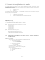
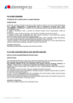
A definite analysis of a return data sequence is possible according to the following diagramm:
Send command sequence
cancel=no
DO
Input data byte date
IF (date<128 or date>0)
Determine from date number*)
Input number of data bytes
ELSE
(read return datas)
IF (date=0)
result=ok
ELSE
result=error
cancel=yes
WHILE(abbruch=nein)
Analyze result
*) This function assigns the length of the return sequence to a command. (see command description)
- page 35 -
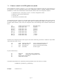
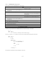
Example:
Command sequence sent with proper process
Plain text:
version
mode 3
• Command sequence, sent byte series:
Byte 0
Byte 1
Byte 2
0x03
0x01
0x09
Byte 3
0x03
Command
length
Command code
VERSION
Command code
MODE
Parameter
„3“
• Return data sequence, received byte series
Byte 0
Byte 1
Byte 2
Byte 3
Byte 4
0x01
0x00
98
03
24
Byte 5
0x00
Marking byte,
Byte signalizes:
4 data bytes
follow
Data byte0
IDENTIFICATION
„LOGLUX“
Data byte1
YEAR
Data byte2
MONTH
Data byte3
DAY
Error code for
whole
sequence:
„ok“
Sent command sequence with incorrect parameters:
Plain text:
mode 72
version
„72“ uncorrect parameter
• Command sequence, sent byte series:
Byte 0
Byte 1
Byte 2
0x03
0x09
72
Byte 3
0x01
Command
length
Command code
MODE
Parameter
„3“
Command code
VERSION
• Return data sequence, received byte series
Byte 0
0xFD
Error code
„illegal
parameter“
The command VERSION was not obeyed because the command MODE was cancelled by an incorrect parameter.
- page 36 -
4 Description of commands
4.1 Table of commands
According to their functions the commands given below can be divided into the following groups:
• Commands for determining the frame data transmission
CAMCLK
LEN
FEN
TRIG
• Commands for determining the frame size and position
RESET
FRAME_SIZE
FRAME_POS
ROT
MIR
• Matching and test commands
HIGH
LOW
CAL
WR
• Enquiring the camera status
VERSION
EEPROM
ADC
• Register commands
VSG
MUX
HDRC
DAC
4.2 Structure of the command description:
COMMAND
Name of the command for plain text mode
• Abstract
Abstract of the commands
Coding of the command in HEX mode
0x00
Return:
Return sequence
Error code
Length of the command: 1 byte
Command length
( × : value is not changed ⇔ : value is changed according to parameter
- page 37 -
0: value = 0 etc. )
RESET
• Reset of all camera settings
0x00
Return:
Error code
Length of command: 1byte
The RESET command allocates all variable configuration parameter with a defined value and re-initializes the
correction RAM.
When calling the RESET command the following MACRO is started:
DAC
DAC
DAC
DAC
MODE
TAB
0, 150
1, 140
2, 128
3, 128
0
4
Configuration:
Bit
8
HDRC reg.
VSG reg. 0
lof
0
7
6
5
4
3
2
1
0
lrm
1
resdir
1
nores
1
gray
1
rowlm
0
Collm
0
rowrm
0
colrm
0
sa
0
step
0
ext_trig
0
gray
1
delay
1
mode
0
prediv
1
VSG reg. 1
VSG reg. 2
len
16
fen
0
VSG reg. 3
VSG reg. 4
x_base
0
y_base
0
x_offset
511
y_offset
255
VSG reg. 5
VSG reg. 6
VSG reg. 7
VSG reg. 8
VSG reg. 9
chaninv
0
DAC reg.0
leninv
1
clkinv
0
clkoff
0
gain
150
offset
140
adcref
128
xxx
128
DAC reg.1
DAC reg.2
DAC reg.3
Correctur table
feninv
1
pipedelay
3
pxlclk
adcclk
0
0
tab (8bit)
4
The contents of the DAC-Backup register and the matching references remain unchanged.
( × : value is not changed ⇔ : value is changed according to parameter
- page 38 -
0: value = 0 etc. )
VERSION
• Enquiring the software version (date of compiling)
0x01
Length of the command: 1byte
Return: 6 byte
0x01
0x00
Error code:
[
year
0]
month
day
error code
ok
The contents of all configuration registers remains unchanged.
$
• Release of the extended command set
0x02
Length of the command: 1byte
Return: 1 byte
Error code
The extended command set is released by the $ command. This makes it possible to have a direct access to the
configuration register. The use of the extended command set requires the exact knowledge of the camera control
because incorrect parameters may cause a malfunction of the camera.
The contents of all configuration registers remains unchanged.
If there is any access to a command of the extended command set (privileged command) without prior release,
the command sequence is cancelled and acknowledged with error code [252].
( × : value is not changed ⇔ : value is changed according to parameter
- page 39 -
0: value = 0 etc. )
DAC
channel, parameter
(privileged command, see $ command)
• Setting the DAC channel
0x03
channel parameter
Length of the command: 3 bytes
Return: 1 byte
Error code
channel: number of the channel (0...3)
channel 0:
channel 1:
channel 2:
GAIN register
OFFSET register
ADCREF register (HIGH reference video ADC)
parameter:
0...255
channel 0:
channel 1:
channel 2:
GAIN register
standard parameter:
OFFSET register standard parameter:
ADCREF register standard parameter:
error code:
[ 0]
[252]
150
140
128
ok
access to privileged command (see $ command)
GAIN register:
The intensification of the video amplifier results from the following
equation:
(
)
V(dB) = 20dB ⋅ value ⋅ 6,78 ⋅10 −3 + 0,381 − 19dB
∆V (db) = ∆value ⋅ 0,136dB
Examples:
Value
0
V(dB)
-11,4dB
ADCREF register:
100
2,2dB
150
9,0dB
200
15,8dB
255
23,2dB
The difference between HIGH and LOW reference (range of converter) of the videoADC results from the following equation:
∆U = 312mV + value ⋅ 5,56mV )
Examples:
Value
100
128
U
868mV 1024m
V
150
200
255
1146mV 1424mV 1730mV
( × : value is not changed ⇔ : value is changed according to parameter
- page 40 -
0: value = 0 etc. )
MUX
channel, switch
(privileged command, see $ command)
• Setting of a multiplex channel
0x04
channel parameter
Length of the command: 3 byte
Return: 1 byte
Error code
channel:
number of the channel (0, 1)
schalter:
switch position (0...3)
error code:
[ 0]
[252]
ok
access to privileged commands (see $ command)
The MUX command activates the camera-internal analog multiplex channel. This command can be used for test
purposes only and has no influence on the camera configuration.
( × : value is not changed ⇔ : value is changed according to parameter
- page 41 -
0: value = 0 etc. )
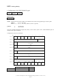
HDRC
parameter
(privileged command, see $ command)
• Loading the HDRC register
0x05
parameter
Length of the command: 2 byte
Return: 1 byte
Error code
parameter:
parameter of the HDRC register (0...255)
error code:
[ 0]
[252]
ok
access to privileged command (see $ command)
The HDRC command sets the HDRC register. If bit 0...4 differs between old and new register parameter, the
correction RAM is additionally re-configured. The selection of the table depends on the TAB register. (See TAB
command)
Configuration by HDRC command:
Bit
HDRC reg.
Correction table
7
6
5
4
3
2
1
0
lrm
Resdir
nores
gray
rowlm
collm
rowrm
colrm
⇔
⇔
⇔
⇔
⇔
⇔
⇔
⇔
tab (8bit)
×
Structure of the HDRC register:
• colrm, column right mirror:
• rowrm, row right mirror:
• collm, column left mirror:
• rowlm, row left mirror:
• gray:
• nores:
• resdir:
• lrm, left right mirror:
By setting this bit the right-hand half of the sensor can be mirrored around
the north-south axis. When addressing column (n), column (255-n) is read
out.
By setting this bit the right-hand half of the sensor can be mirrored around
the east-west axis. When addressing row (n), row (255-n) is read out.
as colrm, left-hand half of the sensor
as rowrm, left-hand half of the sensor
Selection of the addressing code, =0 binary code/ =1 gray code. This bit is
tightly connected with the gray bit VSG reg. 0, bit 4
Suppresses the reset procedure which is processed row by row. The
parameter of this bit should not be changed by the user.
Determines the reset procedure. The parameter of this bit should not be
changed by the user.
By setting this bit, the addressing of the sensor halfs is interchanged. (When
addressing the left-hand half of the sensor, the right-hand half of the sensor is
read out and inverted.)
( × : value is not changed ⇔ : value is changed according to parameter
- page 42 -
0: value = 0 etc. )
VSG
reg, parameter
(privileged command, see $ command)
• Loading of a VSG register
0x06
reg
high
(parameter)
low
(parameter)
Length of the command: 4 byte
Return: 1 byte
Error code
Error code:
[ 0]
[252]
ok
access to privileged commands (see $ command)
high(parameter): High byte register parameter (0, 1)
low(parameter): Low byte register parameter (0, 255)
reg:
register no. (0...9)
Configuration by VSG command:
Bit
8
7
6
5
4
3
2
1
0
VSG reg. reg
⇔
⇔
⇔
⇔
⇔
⇔
⇔
⇔
⇔
VSG configuration register:
VSG register
MODE register
PREDIV register
LEN register
FEN register
X_BASE register
Y_BASE register
X_OFFSET register
Y_OFFSET register
PIPEDELAY reg.
MEASURE reg.
reg
0
1
2
3
4
5
6
7
8
9
Refer to chapter „2.4 Descriptions of function VSG“ for an exact description of the VSG register.
( × : value is not changed ⇔ : value is changed according to parameter
- page 43 -
0: value = 0 etc. )
FRAME_SIZE
X, Y
• Determination of the frame area
0x07
high
(X)
low
(X)
Y
Length of the command: 4 byte
Return: 1 byte
Error code
Erroe code:
[
0]
ok
high(X):(High byte X coordinate)-1
low(X): (Low byte X coordinate)-1
(0, 1)
(0...255)
Y:
(0...255)
(Y coordinate)-1
Example: FRAME_SIZE 199,99
frame area (200×100) pixel
The command FRAME_SIZE determines the frame area which needs to be read out and which depends on the
readout mode set (see command MODE). The following restrictions are valid for this with reference to the area
set:
• MODE 2,3: north-south axial-symmetric frame areas are possible only, even X coordinates only
• MODE 0:
the selection of the frame area is completely free
Configuration by the FRAME_SIZE command:
Bit
VSG reg. 0
8
lof
7
sa
6
step
5
ext_trig
4
gray
3
delay
×
×
×
×
×
×
2
1
mode
0
×
VSG reg. 1
prediv
×
VSG reg. 2
len
×
VSG reg. 3
fen
×
VSG reg. 4
x_base
⇔ /×
× (see table)
VSG reg. 5
y_base
×
VSG reg. 6
x_offset
⇔ (see table)
VSG reg. 7
y_offset
⇔ (see table)
VSG reg. 8
pipedelay
×
VSG reg. 9
chaninv
feninv
Leninv
Clkinv
clkoff
pxlclk
adcclk
×
×
×
×
×
×
×
( × : value is not changed ⇔ : value is changed according to parameter
- page 44 -
0: value = 0 etc. )
VSG-REGISTER
4 (X_BASE)
6 (X_OFFSET)
7 (Y_OFFSET)
MODE 0
×(not changed)
X
Y
MODE2
255-X/2 *
X/2 *
Y
MODE 3
0
X/2 *
Y
* The LSB of the X coordinate is lost when dividing by 2. That is why, a frame area of (300x200) pixel is set each time when applying the
following commands:
FRAME_SIZE 299, 199
FRAME_SIZE 298, 198
( × : value is not changed ⇔ : value is changed according to parameter
- page 45 -
0: value = 0 etc. )
FRAME_POS
X, Y
• Determination of the frame position
0x08
High
(X)
low
(X)
Y
Length of the command: 4 byte
Return: 1 byte
Error code
Error code:
[
0]
ok
high(X):
low(X):
(High byte X coordinate) MODE 0: (0, 1)
(Low byte X coordinate)
(0...255)
Y:
(Y coordinate)
MODE 1,2,3: (0)
(0...255)
The command FRAME_SIZE determines the position of the upper left-hand corner of the image. This depends
on the readout mode set (see command MODE). The following commands are valid with reference to the
varying coordinates:
• MODE 2,3:
• MODE 0:
Y coordinate is variable only (0...255), X coordinate is ignored
the selection of the frame position is completely free
Configuration by the FRAME_POS command:
Bit
VSG reg. 0
8
7
6
5
4
3
2
1
Lof
sa
step
ext_trig
gray
delay
mode
×
×
×
×
×
×
×
VSG reg. 1
0
prediv
×
VSG reg. 2
Len
×
VSG reg. 3
Fen
×
VSG reg. 4
x_base
MODE 0: ⇔(X)
MODE 2,3: ×
VSG reg. 5
y_base
⇔ (Y)
VSG reg. 6
x_offset
×
VSG reg. 7
y_offset
×
VSG reg. 8
pipedelay
×
VSG reg. 9
chaninv
feninv
leninv
clkinv
clkoff
pxlclk
adcclk
×
×
×
×
×
×
×
( × : value is not changed ⇔ : value is changed according to parameter
- page 46 -
0: value = 0 etc. )
MODE
m
• Determination of the readout mode
0x09
m
Length of the command: 2 byte
Return: 1 byte
Error code
Error code:
[
m:
0]
ok
[249]
no symmetric frame area
A switching from single channel mode to dual channel mode is only possible when an
axial-symmetric frame area is set!
[250]
The CAMCLK frequency selected before is not random in the readout mode set.
(e.g. 1MHz selected, afterwards command MODE 3)
Mode
(0,2,3)
The readout mode can be determined with the command MODE:
MODE 0:
single channel mode
MODE 2:
dual channel mode, both halfs of the sensor are convergingly read out
MODE 3:
dual channel mode, both halfs of the sensor are divergently read out
The following parameter remain:
• Frequency fCAMCLK
• Number of clocks LEN, FEN
• Polarity CAMCLK, LEN, FEN
• Frame size and position
Configuration:
Bit
8
HDRC reg.
VSG reg. 0
lof
×
7
6
5
4
3
2
1
0
lrm
1
Resdir
1
nores
1
gray
1
rowlm
⇔
Collm
⇔
rowrm
⇔
colrm
⇔
sa
×
Step
0
ext_trig
×
gray
1
delay
1
VSG reg. 1
VSG reg. 2
Len
⇔
Fen
×
x_base
⇔
y_base
⇔
x_offset
⇔
y_offset
×
VSG reg. 3
VSG reg. 4
VSG reg. 5
VSG reg. 6
VSG reg. 7
VSG reg. 8
VSG reg. 9
mode
⇔
prediv
⇔
chaninv
×
feninv
×
leninv
×
clkinv
×
pipedelay
3
Clkoff
pxlclk
adcclk
×
×
×
( × : value is not changed ⇔ : value is changed according to parameter
- page 47 -
0: value = 0 etc. )
The HDRC register consists of the following:
Readout mode
0
2
3
HDRC register
0xF0
0xF1
0xF4
( × : value is not changed ⇔ : value is changed according to parameter
- page 48 -
0: value = 0 etc. )
LEN
clocks, polarity
• Configuration of the LINE-ENABLE signal
0x0A
clocks
polarity
Length of the command: 3 byte
Return: 1 byte
Error code
clocks: Length of the LEN signal, number of CAMCLK clocks of the LEN signal during its inactive phase
MODE 0:
(0, 1, 2,...254, 255)
MODE 1, 2, 3: (0, 2, 4,...252, 254), (LSB of „clocks“ is ignored)
polarity:
1:
0:
LEN H active
LEN L active
The LEN command determines length and polarity of the inactive phase of the LINE-ENABLE signal as
multiple of the signal CAMCLK.
Configuration by the LEN command:
Bit
8
7
6
5
4
3
2
1
VSG reg. 0
lof
sa
Step
ext_trig
gray
delay
mode
×
×
×
×
×
×
×
VSG reg. 1
0
prediv
×
VSG reg. 2
Len
⇔ (see table)
VSG reg. 3
Fen
×
VSG reg. 4
x_base
×
VSG reg. 5
y_base
×
VSG reg. 6
x_offset
×
VSG reg. 7
y_offset
×
VSG reg. 8
pipedelay
×
VSG reg. 9
MODE 0
MODE 1, 2, 3
chaninv
feninv
leninv
Clkinv
clkoff
pxlclk
adcclk
×
×
⇔
×
×
×
×
VSG reg. 2 (LEN register)
Clocks
Clocks/2
Leninv
polarity
polarity
( × : value is not changed ⇔ : value is changed according to parameter
- page 49 -
0: value = 0 etc. )
FEN
rows, polarity
• Configuration of the FRAME-ENABLE signal
0x0B
rows
Polarity
Length of the command: 3 byte
Return: 1 byte
Error code
clocks:
Length of the FEN signal, number of rows of the FEN signal during its inactive phase
rows=0:
FEN becomes inactive in addition to LEN for frame synchronization
zeilen>0:
FEN becomes inactive for n rows for frame synchronization
polarity:
1:
0:
FEN H active
FEN L active
The FEN command determines length and polarity of the FRAME-ENABLE signal during its inactive phase.
Configuration of the FEN command:
Bit
8
7
6
5
4
3
2
1
VSG reg. 0
lof
sa
Step
ext_trig
gray
delay
mode
×
×
×
×
×
×
×
VSG reg. 1
0
prediv
×
VSG reg. 2
len
×
VSG reg. 3
fen
⇔ (see table)
VSG reg. 4
x_base
×
VSG reg. 5
y_base
×
VSG reg. 6
x_offset
×
VSG reg. 7
y_offset
×
VSG reg. 8
pipedelay
×
VSG reg. 9
chaninv
feninv
leninv
clkinv
clkoff
pxlclk
adcclk
×
⇔
×
×
×
×
×
( × : value is not changed ⇔ : value is changed according to parameter
- page 50 -
0: value = 0 etc. )
CAMCLK
freq, polarity
• Configuration of the CAMCLK signal
0x0C
freq
polarity
Length of the command: 3 byte
Return: 1 byte
Error code
freq:
Frequency in MHz: 1 (Mode 0 only), 2, 4, 8, 16 (Mode 2, 3 only)
polarity:
1:
0:
datas valid for HL edge, data exchange LH edge
datas valid for LH edge, data exchange HL edge
The CAMCLK command determines frequency and polarity of the camera clock.
Configuration by the CAMCLK command:
Bit
8
7
6
5
4
3
2
1
0
VSG reg. 0
lof
sa
step
Ext_tri
gray
delay
mode
×
×
×
g
×
×
×
×
VSG reg. 1
prediv
⇔ (see table)
VSG reg. 2
Len
VSG reg. 3
Fen
×
×
VSG reg. 4
x_base
×
VSG reg. 5
y_base
×
VSG reg. 6
x_offset
×
VSG reg. 7
y_offset
×
VSG reg. 8
Pipedelay
×
VSG reg. 9
chaninv
feninv
leninv
clkinv
clkoff
pxlclk
Adcclk
×
×
×
⇔
×
×
×
Configuration of the PREDIV register (VSG reg. 1)
MODE 0
MODE 2, 3
1MHz
3
-
2MHz
2
3
4MHz
1
2
8MHz
0
1
16MHz
0
( × : value is not changed ⇔ : value is changed according to parameter
- page 51 -
0: value = 0 etc. )
Configuration examples: CAMCLK, LEN, FEN signal
22 >>
22 >>
22 >>
11 >>
11 >>
11 >>
1) Ch 1:
2) Ch 2:
2 Volt 250 ns
2 Volt 250 ns
at the top: CAMCLK
at the bottom: LEN
1) Ch 1:
2 Volt 250 ns
2) Ch 2:
2 Volt 250 ns
1) Ch 1:
2) Ch 2:
at the top: CAMCLK
at the bottom: LEN
Configuration: CAMCLK
LEN
4, 0
4, 0
Configuration: CAMCLK
LEN
4, 1
4, 0
Configuration: CAMCLK
LEN
22 >>
22 >>
22 >>
11 >>
11 >>
11 >>
1) Ch 1:
2) Ch 2:
2 Volt 1 us
2 Volt 1 us
at the top: LEN
1) Ch 1:
2) Ch 2:
at the bottom: FEN
Configuration: FEN 0, 0
Frame size (4×4)pixel
2 Volt 1 us
2 Volt 1 us
1) Ch 1:
2) Ch 2:
at the top: LEN
2 Volt 250 ns
2 Volt 250 ns
at the top: CAMCLK
at the bottom: LEN
at the bottom: FEN
4, 0
2, 1
2 Volt 1 us
2 Volt 1 us
at the top: LEN
at the bottom: FEN
Configuration: FEN 0, 1
Configuration: FEN 1, 0
Frame size (4×4)pixel
Frame size (4×4)pixel
The polarity of the synchronuous signals which needs to be set depends on the type of the attached framegrabber.
Example:
Manufacturer
Type
CAMCLK, LEN, FEN parameter
ELTEC, Mainz
PCEye, CAMA 160
CAMCLK n1, 0 LEN n2, 0 FEN n3, 0
INO-Vision
INOCAP CSD
CAMCLK n1, 0 LEN n2, 1 FEN n3, 1
( × : value is not changed ⇔ : value is changed according to parameter
- page 52 -
0: value = 0 etc. )
ROT
• Rotation of the frame about 180°
0x0D
Length of the command: 1 byte
Return: 1 byte
Error code
Configuration of the ROT command:
Bit
8
HDRC reg.
7
6
5
4
3
2
1
0
lrm
⇔
Resdir
×
nores
×
gray
×
rowlm
⇔
Collm
⇔
rowrm
⇔
colrm
⇔
MIR
• Mirroring of both sensor halfs
0x0E
Length of the command: 1 byte
Return: 1 Byte
Error code
Configuration of the MIR command:
Bit
HDRC reg.
8
7
6
5
4
3
2
1
0
lrm
⇔
Resdir
×
nores
×
gray
×
rowlm
×
collm
⇔
rowrm
×
colrm
⇔
( × : value is not changed ⇔ : value is changed according to parameter
- page 53 -
0: value = 0 etc. )
EEPROM
• Readout of the internal configuration eeprom
0x0F
Length of the command: 1 byte
Return: 130 byte
0x0F
Contents
Adr. 0x00
Contents
Adr. 0x01
Contents
Adr. 0x02
Contents
Adr. 0x03
Contents
Adr. 0x7F
Error code
The EEPROM command outputs the contents of the configuration EEPROM over the
configuration interface. It is possible to read out all configuration parameters with this. The
interpretation of the datas takes place on the controlling PC.
Data assignment in the internal EEPROM:
Address
0x00
0x01
0x02-0x15
0x16-0x19
0x1A-0x29
0x2A
0x2B
0x2C
0x34
0x36
0x38
0x39
0x3A
0x44
0x4E
0x58
Byte
1
1
10×2
4
4×4
1
1
8
2
2
1
1
10
10
10
10
Function
HDRC register
Multiplexer register
VSG register 0...9
DAC channels 0...3
DAC backup for 4 correction tables
Ones complement of the less valuable bytes of the total over
the address 0x1A-0x29 (proof total)
Set correction table
Interface specific datas
BRIGHT reference
DARK reference
GAIN difference
OFFSET difference
Statistical data correction table0
Statistical data correction table1
Statistical data correction table2
Statistical data correction table3
( × : value is not changed ⇔ : value is changed according to parameter
- page 54 -
0: value = 0 etc. )
INTERFACE
par1, par2
• Setting of the interface-specific parameter
0x10
par1
high
(par1)
low
(par1)
Length of the command: 4 byte
Return: 1 byte
Error code
Error code:
[
0]
ok
The modified parameters of the configuration interface can be determined with the INTERFACE command.
The meaning of parameter par1 and par2 depends on the used configuration interface (standard RS232C).
Configuration interface RS232C
The camera permits the determination of a user-specific interface configuration each for the plain text and the
HEX configuration (rate of transmission, number of stop and start bits, parity bits). By setting the configuration
switch (setting 13 for plain text configuration, setting 14 for HEX configuration) on the camera back and
pressing the RESET button afterwards, the setting selected is taken over.
The user-specific interface configuration can be undone by shifting the configuration switch to setting 0...12 at
any time.
Meaning of the Parameter :
par1
=0:
=1:
Setting of interface parameter for plain text configuration
Setting of interface parameter for HEX configuration
par2:
Interface parameter word
Structure:
Bit
14
=0: 8bit
=1: 7bit
13
12
Parity:
=00: none
=10: EVEN
=11: ODD
11
Stopbit
:
=0: 1
=1: 2
10
0
9
8
Predivider
n
7
6
5
4
3
2
Transmission rate
N
The Baud rate B results from parametern n and N as follows:
N=
Φ
2
( 2 n + 5)
⋅B
−1
B=
2
( 2 n + 5)
Φ
⋅ ( N + 1)
Φ = 8 ⋅ 106 Hz
Error E of the Baud fate in %:
( × : value is not changed ⇔ : value is changed according to parameter
- page 55 -
0: value = 0 etc. )
1
0
Φ
⋅ 100%
E =
−
1
n
+
2
5
(
)
( N + 1) ⋅ B ⋅ 2
Φ = 8 ⋅ 106 Hz
Example:
Baud rate
[Bd]
110
n
N
2
141
Error
[%]
0,03
150
2
103
0,16
300
1
207
0,16
600
1
103
0,16
1200
0
207
0,16
2400
0
103
0,16
4800
0
51
0,16
9600
0
25
0,16
19200
0
12
0,16
31250
0
7
0
Interface parameter for plain text configuration: 4800Bd, 2 stop bits, parity EVEN:
INTERFACE 0, 0x2833
INTERFACE 0, 10291
Setting of a user-specific transmission rate:
1. Obeying the INTERFACE command in plain text or HEX mode
2. Setting of the configuration switch (setting 13: plain text mode, setting 14: HEX mode)
3. Pressing the RESET button or restarting the camera by switching off and on the power supply.
Notes: In HEX mode and when transmitting datas with the XMODEM control protocol in plain text mode,
always 8 data bits need to be transmitted.
( × : value is not changed ⇔ : value is changed according to parameter
- page 56 -
0: value = 0 etc. )
TAB
table
• Setting of a correction table
0x11
table
Length of the command: 2 byte
Return: 1 byte
Error code
The TAB command selects a correction table. The following assignment is valid:
TAB
0
1
2
3
4
5
6
7
8
9
10
11
12
13
14
15
16
17
18
19
20
21
22
23
Correction table 0 from FLASH-ROM
Correction table 1 from FLASH-ROM
Correction table 2 from FLASH-ROM
Correction table 3 from FLASH-ROM
Not corrected frame
Test pattern for GAIN and OFFSET
Correction table 0 from FLASH-ROM
Correction table 1 from FLASH-ROM
Correction table 2 from FLASH-ROM
Correction table 3 from FLASH-ROM
Not corrected frame
Test pattern for GAIN and OFFSET
Correction table 0 from FLASH-ROM
Correction table 1 from FLASH-ROM
Correction table 2 from FLASH-ROM
Correction table 3 from FLASH-ROM
Not corrected frame
Test pattern for GAIN and OFFSET
Correction table 0 from FLASH-ROM
Correction table 1 from FLASH-ROM
Correction table 2 from FLASH-ROM
Correction table 3 from FLASH-ROM
Not corrected frame
Test pattern for GAIN and OFFSET
Additional inlaying of the
main setting datas
• X direction: GAIN
• Y direction: OFFSET
Additional inlaying of the
frame size
Additonal inlaying of the main
setting datas
• X direction: GAIN
• Y direction: OFFSET
( × : value is not changed ⇔ : value is changed according to parameter
- page 57 -
0: value = 0 etc. )
HIGH
parameter
(privileged command, see $ command)
• Definition of the BRIGHT reference (see CAL command)
0x12
high
low
(parameter) (parameter)
Length of the command: 3 byte
Return: 1 byte
Error code
LOW
parameter
(privileged command, see $ command)
• Definition of the DARK refernce (see CAL command)
0x13
high
low
(parameter) (parameter)
Length of the command: 3 byte
Return: 1 byte
Error code
( × : value is not changed ⇔ : value is changed according to parameter
- page 58 -
0: value = 0 etc. )
CAL
table, parameter
(privileged command, see $ command)
• Calibration of the camera
0x14
table
parameter
Length of the command: 3 byte
table:
No. of the correction table in FLASH-ROM (aim for calibration datas, 0...3)
parameter:
0: rough correction only, correction table is described as mean value
1: OFFSET fine correction
2: GAIN fine correction
3: GAIN and OFFSET fine correction
Return: 1 byte
Error code
The CAL command serves the automatic trimming of the camera on a calibrated light
generator. At the same time the camera parameter are varied this way that a defined
luminance results in a certain absolute value and a luminance jump leads to a defined value
difference on the exit.
The numerical values for the high and low luminance are reconcilled with HIGH or LOW.
The following connection exists between luminance and numerical value.
− 16
L
1 k
32
= 683
⋅ ⋅2
L0
τ ⋅ π k0
2
Z
Z =numerical value(10bit)
L: luminance of the light generator in cd/m2
L0=4cd/m2
k: aperture of the lens
k0=1
τ : Transmission degree of the lens (approx. 0,8)
The setting of different luminances is required by the blinking of the camera LED:
yellow-red: high luminance
yellow-green: low luminance
yellow:
calibration is in progress
The change of luminance has to be acknowledged by pressing the button on the camera back
(button next to RESET). The use of an automatically controlled light generator is described in
chapter „Operation with automatic light generator“.
( × : value is not changed ⇔ : value is changed according to parameter
- page 59 -
0: value = 0 etc. )
WR
adr, date
(privileged command, see $ command)
• Description of the internal EEPROMS
0x15
adr
date
Length of the command: 3 byte
Return: 1 byte
Error code
Error code:
[
0]
ok
adr:
date:
EEPROM address (0...127)
0...255
Attention: This command serves test patterns only! An overwriting of the internal proof totals by accident
results in an initialization of the camera connected with losing all calibration data.
TRIG
par
• Switching on of the external frame trigger
0x16
par
Length of the command: 2 byte
Return: 1 byte
Error code
Error code:
[
0]
ok
par
=0:
External frame trigger OFF
The readout of the sensor is continuously done
par
=1:
External frame trigger ON
With a rising edge on the FRAME_TRIG input one frame is read out. Afterwards the camera
remains in waiting state.
Configuration:
Bit
8
7
6
5
4
3
2
1
VSG reg. 0
lof
sa
step
Ext_tri
gray
delay
mode
×
×
×
g⇔
×
×
×
( × : value is not changed ⇔ : value is changed according to parameter
- page 60 -
0
0: value = 0 etc. )
ADC
channel
(privileged command, see $ command)
• Enquiring the internal AD converter for test purposes
0x17
channel
Length of the command: 2 byte
Return: 4 byte
0x17
high
(adc_parameter)
Error code:
[
0]
low
(adc_parameter)
Error
code
ok
adc_parameter: value of voltage in mV
// (Comment)
• Marking of an command line as comment
0x18
Length of the command: 1 byte
Return: 1 byte
Error code
Error code:
[
0]
ok
The „//“ command marks a command line as comment and improves the overall view of configuration files in
connection with the TERMINAL menu point „Send text file“. The camera settings are not changed during the
obeying process.
The application is only useful in plain text mode.
Example:
Text file INO_VIS.TXT for configuring the camera for a connection to an INO-VISION framegrabber, created
with WRITE (Windows) or EDIT (DOS):
// INO-Vision configuration, 8MHz
// LINE-, FRAME-Enable LOW active
len 16,1
fen 0,1
camclk 8,0
( × : value is not changed ⇔ : value is changed according to parameter
- page 61 -
0: value = 0 etc. )
GAIN
gain_difference
• Setting of a gain difference
0x19
gain_difference
Length of the command: 2 byte
1
Return: 1 byte
Error code
Error code:
[ 0] ok
[253] illegal parameter
gain_difference: parameter for gain difference, range 0...45
The „GAIN“ command permits to increase the gain of the video amplifier. At the same time a constant
difference to the value of the DAC register which is determined when calibrating the camera is laid down. This
results in a constant rise of the gain independent of the calibration results. The set gain difference is considered
as independent of the correction table set.
The connection of the parameter „gain_differenz“ ∆Z and the rise of the gain results from the following equation:
∆V = ∆Z ⋅ 0,136dB
Example:
∆Z
∆V in dB
15
≈2
OFFSET
offset
22
≈3
29
≈4
37
≈5
44
≈6
• Setting of the brightness offset
0x1A
offset
Length of the command: 2 bytes
Return: 1 byte
Error code
Error code:
[ 0]
[253]
ok
illegal parameter
offset: parameter of the brightness offset, range 0...50
The „Offset“ command permits a change of the frame brightness independent of the DAC offset parameter
determined when trimming the camera. Consequently, the ascertainable brightness range can be determined in
connection with a gain rise by the gain command. A higher value for „offset“ results in a darker frame. The set
offset parameter is valid for all correction tables.
STAT
table
(privileged command, see $ command)
( × : value is not changed ⇔ : value is changed according to parameter
- page 62 -
0: value = 0 etc. )
• Enquiring statistical parameter of the correction table „table“ for control purposes
0x1B
table
Lenght of the command: 2 byte
Return: 32 byte
0x1B
Byte 2
...
Error code:
[ 0]
[253]
table:
correction table 0...3
Byte 31
fehler-code
ok
unvalid parameter
With the STAT command it is possible to make a statement about the statisitical distribution of the corresponding correction files. Byte 2...31 contain the following information:
Byte #
Meaning
High
2
Low
3
4
6
8
10
12
14
16
18
20
22
24
26
28
30
5
7
9
11
13
15
17
19
21
23
25
27
29
31
Sensor data
Bit 2...15: Difference
INSTANTANEOUS-DESIRED
value of the mean brightness
figures after the calibration
(complement on two)
Standard drift (68% interval), sensor roughly corrected
99% interval, sensor roughly corrected
Standard drift (68% interval), sensor fine corrected
99% interval, sensor fine corrected
Offset-correction Mean value instantaneous value (desired value: 512)
file
68% interval (standard drift), =0 when correction file is empty
99% interval
90% interval
50% interval
Gain-correction Mean value instantaneous value (desired value: 32)
file
68% interval (standard drift)
99% interval
90% interval
50% interval
Bit 0,1: selected parameter of the
„CAL“ command
0: rough cal. 1: OFFSET
2: GAIN
3: GAIN+OFFSET
( × : value is not changed ⇔ : value is changed according to parameter
- page 63 -
0: value = 0 etc. )
4.3 Commands for transmitting bigger data quantities
The internal software of the LOGLUX camera permits a transmission of bigger data quantities with the
XMODEM control protocol. The protocol provides an error control of the data transmitted. The command for
the XMODEM data transmission
1.
2.
LOAD par1, par2
SAVE pars
are available for certain camera setting only. As the XMODEM transmission relies on 8 transmitted data bits, the
following settings need to be adjusted:
1.
2.
configuration in plain text mode
quantity of transmitted data bits of the RS232 interface: 8bit
LOAD par1, par2
•
Transmitting a file from control computer to camera
par1:
Determination of the contents of the file which is to transmit
0: correction table 0
1: correction table 1
2: correction table 2
3: correction table 3
par2:
Determination of the control protocol
0: Requirements XMODEM control protocol
1: Requirements XMODEM/CRC control protocol
4.3.1 Sending of files in XMODEM format with the WIN3.1x -, WIN 95- TERMINAL
(VT100 emulation)
Windows 3.1x-Terminal:
1. Menu „setting“ (only when configuring the terminal for the first time)
1.1 Menu „binary transmission“
• Activate XMODEM/CRC
1.2 Menu „modem commands“
• Activate NONE
2.
3.
4.
Input camera command „LOAD par, 1↵“
Wait for „LOGLUX ready for receiving a binary file...“
Menu „transmission“
4.1 Menu „SEND BINARY FILE“
4.2 Select file
4.3 OK
- page 64 -
Windows 95 - HyperTerminal:
1.
2.
3.
Send camera command „LOAD par1,par2↵“
Wait for „ LOGLUX ready for receiving a binary file...“
Menu „transmission“
3.1 Menu „SEND FILE“
3.2 Select file
3.3 Activate Xmodem
3.4 OK
Should any problems arise when transmitting datas (transmission does not start), select menu „FILE
→PREDICATES →SELECTION NUMBER →CONFIGURATION →PROTOCOL“ „NONE“.
SAVE par
•
Transmitting a file from camera to control computer
par:
par
0
1
2
3
4
5
6
7
8
9
10
11
12
13
14
15
16
17
18
19
20
21
22
23
Determining the contents of the file which is to transmit
Windows *.BMP file
Palett: gray scales
Windows *.BMP file
Palett: gray scales
Marking overshoot of range
Text file*.TXT
ASCII code
File
Binary file: correction table 0
Binary file: correction table 1
Binary file: correction table 2
Binary file: correction table 3
Bit 2...9 of the recorded 10bit frame
Restricted value range 1 (see below)
Restricted value range 2 (see below)
Bit 2...9 of the recorded 10bit frame
Restricted value range 1 (see below)
Restricted value range 2 (see below)
Binary file: single frame 10bit
Set camera parameter
Calibration statistics
Set camera parameter, configuration statistics
Calibration statistics for EXCEL table
10bit single frame histogramm for EXCEL
Histogramm offset correction table 0 for EXCEL
Histogramm gain correction table 0 for EXCEL
Histogramm offset correction table 1 for EXCEL
Histogramm gain correction table 1 for EXCEL
Histogramm offset correction table 2 for EXCEL
Histogramm gain correction table 2 for EXCEL
Histogramm offset correction table 3 for EXCEL
Histogramm gain correction table 3 for EXCEL
- page 65 -
Calculation of the restricted value range:
Processing steps:
1.
Calculation of the mean frame brightness M
2.
Subtraction of the mean frame brightness from all 10bit pixel values P(x,y) (complement on two)
3.
Assigning the difference D(x,y)=P(x,y)-M according to the following scheme:
Range
1:
if D(x,y) < -256
then D(x,y) = -256
if D(x,y) > 255
then D(x,y) = 255
gray scale(x,y) = D(x,y)/2+128
range 2:
if D(x,y) < -128
then D(x,y) = -128
if D(x,y) > 127
then D(x,y) = 127
gray scale(x,y) = D(x,y)+128
4.3.2 Receiving of files in XMODEM format with the WIN3.1x -, WIN 95TERMINAL (VT100 emulation)
Windows 3.1x-Terminal:
1. Menu „settings“ (only when configuring the terminal for the first time)
1.1 Menu „Binary transmission“
• Activate XMODEM/CRC
1.2 Menu „Modem commands“
• Activate NONE
2. Input camera command „SAVE par↵“
3. Wait for „ LOGLUX ready for sending a binary file...“
4. Menu „Transmission“
4.1 Menu „BINARY FILE RECEIVED“
4.2 Select file
4.3 OK
Windows 95 - HyperTerminal:
1. Send camera command „LOAD par1,par2↵“
2. Wait for „ LOGLUX ready for sending a binary file...“
3. Menu „Transmission“
3.1 Menu „Send file“
3.2 Select file which is to receive
3.3 activate Xmodem
3.4 OK
Should any problems arise when transmitting datas (transmission does not start), select menu „FILE
→PREDICATES →SELECTION NUMBER →CONFIGURATION →PROTOCOLL“ „NONE“.
- page 66 -
4.3.3 Structure of the correction file
One correction file is sent by the camera when obeying the command SAVE 0...3 and has the following structure:
Lenght of file, total:
Consisting of: file head:
correction data
262170 bytes
26 bytes
262144 bytes (0,25 MB)
Structure of the data head:
Byte
Description
0...7
Character string: „LOGLUX“
8
Device code: =0
9
Software version:
year
10
month
11
day
Calibration values GAIN, reg. 0
12
DAC register
13
OFFSET, reg. 1
14
ADCREF, reg. 2
15
VRESET, reg. 3
16 17 Statistical data,
Drift of desired
Sensor calibration value
18 19
68% interv., uncorr.
20 21
99% interv., uncorr.
22 23
68% interv., corr.
99% interv., corr.
24 25
Structure of correction data block:
Byte
Structure 16bit word
HIGH
LOW
0
1
Bit 0...9: OFFSET
Bit 10...15: GAIN
...
...
510
511
512
513
...
..
131070 131071
131072 131073
...
...
131582 131583
131584 131585
...
...
262142 262143
Correction data: pixel coordinate
X
0
...
0
Left sensor half
1
...
255
256
...
511
Right sensor half
256
...
511
Y
0
...
255
0
...
255
0
...
0
1
...
255
Please note: The coordinate origin is located in the upper left-hand corner of the sensor (NW corner).
[0,0]
...
[255,0]
[256,0]
...
[511,255]
...
...
...
...
...
...
[0,255]
...
[255,255]
[256,255]
...
[511,255]
- page 67 -
4.3.4 Structure of a 10bit frame file
Beginning with the coordinate [0,0] pixel values are ascendingly saved as 16bit words in a 10bit frame file. Bit
10...15 is set =0. This results in file size of 0,25Mbyte = 256kByte. The higher-quality byte of the 16bit word is
located on a lower address:
Address n
HIGH-Byte
Structure of the 10bit frame file:
[0,0]
...
0x00000
Address (n+1)
LOW-Byte
[255,0]
0x001FE
[256,0]
0x00200
...
[511,255]
0x003FE
...
...
...
...
...
...
[0,255]
0x3FC00
...
[255,255]
0x3FDFE
[256,255]
0x3FE00
...
[511,255]
0x3FFFE
4.3.5 Structure of a text file for infixing a MS-EXCEL table
The text files which are to infix in Microsoft EXCEL have the following characteristics:
1.
2.
3.
4.
5.
Characters of the ASCII code are transmitted only (<0x80)
Data columns are seperated by commas.
Data rows are seperated by CR (0x0D) LF(0x0A).
Numbers are given in decimal style.
Character strings are marked by quotation marks (").
Example: A text file with the following contents (part) is interpreted by MS-EXCEL as shown below:
Text file *.txt
"LOGLUX histogramm(GAIN)",0,0
,1,0
,2,0
,3,0
,4,0
,5,0
,6,0
...
EXCEL table *.xls
LOGLUX histogramm(GAIN)
0
1
2
3
4
5
6
0
0
0
0
0
0
0
- page 68 -
4.3.6 Description of the XMODEM control protocol
4.3.6.1
General features
The XMODEM control protocol permits a transmission of bigger data quantities over a serial interface. The
transmission is carried out in 128byte blocks. Should a transmission error arise, the uncorrect block is transmitted once more. A further development of the XMODEM control protocol is the XMODEM/CRC control
protocol. It is more fault-tolerant because of the use of a CRC checksum (CRC: Cyclical Redundancy Check). A
transmission with the XMODEM control protocol requires the possibility to transmit 8 data bits. This must be
done without a control with the XON/XOFF control protocol.
In principel every data block is structured as follows:
ASCII characters
SOH
0x01
Block number (255-Block no.)
128 Data bytes
checksum
XMODEM: 1byte
XMODEM/CRC: 2byte
XMODEM and XMODEM/CRC data blocks differ from each other only in their structure of the checksum.
4.3.6.2
XMODEM control protocol
Data transmission with the XMODEM control protocol
Data sender
1.
2.
3.
Data receiver
Receiver signals standby with sending the ASCII
character NAK (0x15)
(Cancel of the data transmission by sending the
ASCII character CAN (0x18), then immediate stop
of transmission)
Sending of a data block (132 byte)
4.
5.
6.
(Cancel of the data transmission by sending the
ASCII character CAN (0x18), then immediate stop
of transmission)
Controlling the checksum
Sending the ASCII character ACK (0x06) when
the data transmission is ok, otherwise NAK (0x15)
7.
(Cancel of the data transmission by sending the
ASCII character CAN (0x18), then immediate stop
of transmission)
8. When receiving NAK the data block is sent once
more, otherwise sent next data block
9. Repeat steps 4...8 until all data blocks are transmitted
10. Send the ASCII character EOT (0x04) for stoping
the data transmission
11. Sending the ASCII character NAK (0x15)
12. Sending the ASCII character EOT (0x04)
13. Sending the ASCII character ACK (0x06)
14. Transmission finished
Calculation of the checksum for the XMODEM control protocol (1byte):
checksum = (Sum over all 128 data bytes) & 255
- page 69 -
4.3.6.3
XMODEM/CRC control protocol
Data transmission with the XMODEM/CRC control protocol
Data sender
Data receiver
1. Receiver signals standby with sending the ASCII
character „C“ (0x43)
2. (Cancel of the data transmission by sending the
ASCII character CAN (0x18), then immediate stop
of transmission)
3. Sending a data block (133 bytes)
4. (Cancel of the data transmission by sending the
ASCII character CAN (0x18), then immediate stop
of transmission)
5. Controlling the checksum
6. Send the ASCII character ACK (0x06) when the
data transmission is ok, otherwise NAK (0x15)
7. (Cancel of the data transmission by sending the
ASCII character CAN (0x18), then immediate stop
of transmission)
8. After receiving NAK, send the data block once
more, otherwise send next data block
9. Repeat steps 4...8 until all data blocks are transmitted
10. Sending the ASCII character EOT (0x04) for
stopping the data transmission
11. Sending the ASCII character NAK (0x15)
12. Sending the ASCII character EOT (0x04)
13. Sending the ASCII character ACK (0x06)
14. Transmission is finished
Calculation of the checksum for the XMODEM/CRC control protocol (2byte), 1 Data block:
crc = 0
FOR z=0 TO 127
crc = (crc*256) xor (crctabelle[(crc/256) xor data byte[z]])
The Array „crctabelle[...]“ is a constant. Its contents can be calculated when following these instructions:
FOR i=0 TO 255
a=0
k=i*256
FOR j=0 TO 7
IF (((k xor a) and 0x8000) <>0)
a = (a*2) xor 4129
ELSE
a = (a*2)
k = k*2
crctabelle[i] = a
The checksum is transmitted in the order HIGH byte, LOW byte.
- page 70 -
4.4 Operation with automatic light generator
The control software of the LOGLUX camera permits the attachment of an automatic light generator to the
camera-internal I2C bus. A 5-pole JST plug (CON6) which is on the circuit 6000 1 0400 (H8 board) from index
C on is proveded for this and has the following load:
PIN no.
1
2
3
4
5
load
SCL (clock I2C bus)
SDA (data signal I2C bus)
GND
free
DV3,3
The initialization routine looks on the I2C bus for connected subscriber with the addresses 0x40, 0x42, 0x44,
0x70, 0x72 and 0x74. If a subscriber is found in one of these addresses, the following message appears in plain
text mode:
Light generator addr.: address
The calibration routine (command CAL) takes on an 8bit port on this address. Consequently, the use of the
Philips I2C port PCF8574 or PCF8574A is possible.
The single bits of the IO port are described, selected or enquired as shown below:
Bit no.
0
1
2
3
4
5
6
7
Input/output
Output
Output
Input
Input
Output
Output
Output
Output
Meaning
Aperture motor reverse action, LOW active
Aperture motor right action, LOW active
End position switch 1, LOW active (=LOW: end position 1 detected)
End position switch 2, LOW active (=LOW: end position 2 detected)
„BRIGHT“, LOW active
„DARK“, LOW active
„CALIBRATIO IS RUNNING“, LOW acktive
„CALIBRATION IS FINISHED“, LOW active
According to the ascertained I2C address the signals „reverse/right action“ are selected in different ways and the
signals „end position 1/-2“ are interpreted in different ways.
I2C address
PCF8574
PCF8574A
0x40
0x70
0x42
0x72
0x44
0x74
Selecting scheme
End position switch 1,2
Aperture motor outputs
„BRIGHT“: reverse action =LOW
„DARK“: right action =LOW
End position switch 1 =LOW: „BRIGHT“
End position switch 2 =LOW: „DARK“
„BRIGHT“ / „DARK“:
reverse action =LOW
right action: without meaning
End position switch 1 =LOW: „BRIGHT“
End position switch 1 =HIGH: „DARK“
When the camera trimming is finished, bit 7 („CALIBRATION FINISHED“) is activated for approx. 1s
(acoustic signal).
A determination of bit 1,2 of the I2C address can be carried out over a DIP switch.
- page 71 -
Beschreibung LOGLUX-Kamera, Sachwortverzeichnis
5 Glossary
D
$
DAC command ................................................ 40
Data interface...................See frame data interface
Data sorting ....................... See frame data sorting
Dark - determine reference ............................... 58
delay bit ........................................................... 23
Description of commands ................................. 37
Dual-Port-RAM ............................................... 26
Dual channel mode........................................... 19
$ command .......................................................39
/
// command.......................................................61
A
ADC command.................................................61
adcclk - bit........................................................25
ADCREF register..............................................40
ADC converting area ..........................................9
Aperture f ...........................................................7
ASCII control ...................................................29
ASCII control ...................................................33
Assessment of the range....................................11
E
Echo ................................................................ 33
EEPROM, Data assignment.............................. 54
EEPROM command......................................... 54
ESCAPE sequences.......................................... 33
F
B
Error codes, table ............................................. 35
FEN ................................................................. 14
fen bits............................................................. 25
FEN register..................................................... 24
FEN command ................................................. 50
feninv bit ......................................................... 25
Fixed Pattern Noise ............................................ 5
Correction of the ... .......................................... 5
f-number ............................................................ 7
FPN ................................. See Fixed Pattern Noise
Frame data interface ......................................... 13
Pin load ......................................................... 15
Feeder cable................................................... 16
Frame file 10bit, structure................................. 68
Frame data sorting............................................ 26
FRAME_POS command .................................. 46
FRAME_SIZE command ................................. 44
FRAMETRIG .................................................. 14
Function keys................................................... 33
BACKUP..........................................................33
Baud rate ..........................................................32
BINARY code ..................................................17
Binary logarithm.................................................5
BRIGHT - determine reference .........................58
Brightness E .......................................................8
Brightness conditions........................................11
Brightness sensitivity, physiological....................8
C
CAL command .................................................59
Calibration of camera..........................................6
starting ...........................................................59
Calibration equation............................................9
Description .....................................................10
logarithmic form...............................................9
CAMCLK.........................................................14
CAMCLK command.........................................51
Cascade transformer..........................................24
chaninv bit........................................................25
Characteristic impedance...................................13
clkinv bit ..........................................................25
clkoff bit...........................................................25
collm bit ...........................................................17
colrm bit ...........................................................17
Column address counter ....................................19
column left mirror..................................See collm
column right mirror............................... See colrm
Command, structure..........................................34
Comment command ..........................................61
Common Mode Voltage .............See offset voltage
Configuration of the camera ..............................29
Configuration bus .............................................12
Configuration interface......................................12
Configuration switch................................... 12, 32
Correction file, structure....................................67
Correction table
determine........................................................57
Correction table ................................................29
G
GAIN command............................................... 62
GAIN register .................................................. 40
Gray scale ........................................................ 11
Gray bit
HDRC............................................................ 17
VSG .............................................................. 23
Gray code......................................................... 17
H
HDRC command.............................................. 42
HDRC4 sensor
Description of functions ................................. 17
HEX control................................................29, 34
HIGH command............................................... 58
Histogramm for MS-EXCEL............................ 68
I
I2C bus............................................................. 71
INTERFACE command ................................... 55
- page 72 -
Beschreibung LOGLUX-Kamera, Sachwortverzeichnis
RESET command............................................. 38
ROT command................................................. 53
Row address counter ........................................ 19
row left mirror...................................... See rowlm
row right mirror ...................................See rowrm
rowlm bit ......................................................... 17
rowrm bit ......................................................... 17
RS232C ........................................................... 29
PIN load ........................................................ 30
RS422.........................................................13, 31
PIN load ........................................................ 31
RS232C ........................................................55
Irradiance Ee ...................................................6, 8
L
LED, signal- .....................................................31
left right mirror ......................................... See lrm
LEN..................................................................14
len bits..............................................................24
LEN register .....................................................24
LEN command..................................................49
leninv bit ..........................................................25
Light generator, automatic.................................71
LOAD command ..............................................64
lof bit.......................................................... 14, 23
Low Voltage Differential Signaling...... See LVDS
LOW command ................................................58
lrm bit...............................................................17
Luminance..........................................................7
LVDS ...............................................................13
S
sa bit ................................................................ 23
SAVE command .............................................. 65
Sensor brighness ES ............................................ 7
Set of commands, Release of extended...See $
command
Examples
Sequence of commands .................................. 36
Brightness........................................................ 7
CAMCLK, LEN, FEN signal ......................... 52
Pixel addressing ............................................. 18
Reflexion factor ............................................... 8
Transmission rate, user-defined ...................... 56
Single channel mode ........................................ 19
Standard subject, photographic ......................... 11
STAT command............................................... 63
step bit ............................................................. 23
Subject brightness EOB ...................................7, 11
Subject luminance LOB ...................................7, 11
M
Marking byte ....................................................35
MEASURE register ..........................................24
MIR command..................................................53
mirror bit..........................................................17
mode bits ..........................................................23
MODE register .................................................22
Mode 0 .............................................................19
Mode 2 .............................................................19
Mode 3 .............................................................19
MODE command..............................................47
MUX command ................................................41
T
O
TAB command................................................. 57
Terminator ..................................................13, 31
Transmissions level τ ......................................... 9
Transmission rate ............................................. 32
user-defined ................................................... 55
trig bit.............................................................. 23
TRIG command ............................................... 60
Trigger, external............................................... 60
Octavo skip.........................................................5
OFFSET register...............................................40
OFFSET command ...........................................62
Offset voltage ...................................................13
P
Parity................................................................32
Pipeline-ADC ...................................................24
PIPELINE-DELAY register ..............................24
Plain text control.......................See ASCII control
Power densitiy, spectral.......................................8
prediv bits.........................................................23
PREDIV register...............................................22
Protocol, RTS/CTS-..........................................29
pxlclk bit ..........................................................25
U
UNDO ............................................................. 33
V
V(λ)................................................................... 8
Variable Scan Generator...................... Siehe VSG
VERSION command........................................ 39
VSG
Description of functions ................................. 19
VSG command................................................. 43
VT100 terminal................................................ 29
Q
Quantities
light-technical...................................................8
radiation-physical... ..........................................8
W
R
Working area of the camera................................ 6
WR command .................................................. 60
Radiation density Le ............................................8
Radiation equivalent, photometric .......................8
Radiation-physical, determinations......................6
Readout, converging ........................... See mode 2
Readout, divergent .............................. See mode 3
Reflexion, diffuse................................................7
Reflexion factor ρ .........................................7, 11
X
x_base register ................................................. 20
x_offset register ............................................... 20
XMODEM protocol ......................................... 64
- page 73 -
Beschreibung LOGLUX-Kamera, Sachwortverzeichnis
y_offset register ............................................... 20
Description .....................................................69
Receiving of files............................................66
Sending of files...............................................64
Z
Zero modem cable............................................ 30
Y
y_base register ..................................................20
- page 74 -
Beschreibung LOGLUX-Kamera, Anhang
6 Appendix
6.1 Table: Plug load
6.1.1 Power supply
free
Frame data
Interface
LVDS
RS422
VCC
VCC
5,5...6,2 V
GND
LWL
IB
Plug
450mA
700mA
Binder
09-0407-00-03
Thomas & Betts
T01-0560-P03
650mA
6.1.2 RS232/RS422 Configuration interface
6
1
7
2
8
3
9
4
5
9-pole D-Sub, plug
Pin no.
1
2
3
4
5
6
7
8
9
RS232
RxD
TxD
/RTS
/CTS
RS422 (optinal)
With 4,6 connected
RxD+
TxD+
With 1,6 connected
GND
With 4,1 connected
RxDTxDfrei
6.1.3 RS422/LVDS Frame data interface
15 14
2 1
30
6
16
6
44
1
2
3
4
5
6
7
8
9
10
11
12
13
14
15
31
D0+
D1+
D2+
D3+
D4+
D5+
D6+
D7+
D8+
D9+
LEN+
FEN+
CAMCLK+
OTR+
FRAMETR+
16
17
18
19
20
21
22
23
24
25
26
27
28
29
30
D0D1D2D3D4D5D6D7D8D9LENFENCAMCLKOTRFRAMETR-
- page 75 -
31
32
33
34
35
36
37
38
39
40
41
42
43
44
SDA
SCL
GND
GND
GND
GND
frei
frei
frei
frei
3,3V
3,3V
5V
5V
Beschreibung LOGLUX-Kamera, Anhang
6.2 Table: Lenses for LOGLUX
Designation
Pict.
Focal
Aperture
length f'
Camera connection angle
range
[mm]
(2σ')
Recording range
Distance setting
LOGLAR T 2/13
13,2
2 (fixed)
over 0 plate
(M16 x 0,5)
49°
∞ ... 2m
("Fixed focus")
On customer’s demand
Fixed settings up to approx.
0,2m possible
DOCTAR 5/13,5
13,51
5 (fixed)
C-Mount plate
(1" x 32 TPI)
48°
∞ ... 0,2m
Over lens connection
thread
LOGLAR T 2,8/16
16,3
2,8
(fixed)
over 0 plate
(M16 x 0,5)
41°
∞ ... 2,3m
("Fixed focus")
On customer’s demand
Fixed settings up to approx.
0,3m possible
LOGLAR T 4/16
16,3
4 (fixed)
over 0 plate
(M16 x 0,5)
41°
∞ ... 1,6m
("Fixed focus")
On customer’s demand
Fixed settings up to approx.
0,3m possible
LOGLAR T 8/16
16,3
8 (fixed)
over 0 plate
(M16 x 0,5)
41°
∞ ... 0,8m
("Fixed focus")
On customer’s demand
Fixed settings up to approx.
0,3m possible
TEVIDON 1,4/25
25,4
1,4 ... 16
C-Mount plate
(1" x 32 TPI)
27°
∞ ... 0,3m
over lens setting ring
ROTAR T 4,5/29
29,85
4,5 ... 16
C-Mount plate
(1" x 32 TPI)
23°
∞ ... 0,3m
Continuously up to approx.
5mm
Lens extension over mount
Tessar T 3,5/37,5
37,5
3,5
(fixed)
C-Mount plate
(1" x 32 TPI)
19°
∞ ... 0,2m
Continuously up to approx.
12mm
Lens extension over mount
MAKRO-TV 4/45
45,3
4 (fixed)
C-Mount plate
(1" x 32 TPI)
Up to
10°
79 ... 124mm
Operation distance
over lens setting ring for
macro range 1:1 to 1:2
ROTAR T 4,5/50 S
50,75
4,5 ... 22
C-Mount plate
(1" x 32 TPI)
14°
∞ ... 0,4m
Continuously up to approx.
10mm
Lens extension over mount
Tessar T 3,5/50
51,43
3,5
(fixed)
C-Mount plate
(1" x 32 TPI)
14°
∞ ... 0,3m
Continouosly up to approx.
14mm
Lens extension over mount
Tessar T 3,5/70
70,3
3,5
(fixed)
C-Mount plate
(1" x 32 TPI)
10°
∞ ... 0,65m
Continuously up to approx.
10mm
Lens extension over mount
ROTAR T 6,5/75
73,5
6,5 ... 22
C-Mount plate
(1" x 32 TPI)
10°
∞ ... 0,3m
Continuously up to approx.
11mm
Lens extension over mount
TEVIDON 2,8/100
96,5
2,8 ... 16
C-Mount plate
(1" x 32 TPI)
8°
∞ ... 1,5m
over lens setting ring
LOGLAR 19/320
makro
317,3
19
(fixed)
C-Mount plate
(1" x 32 TPI)
bis 2°
0,6 ... 3m or ∞
operation distance
Over adaptor for macro
range 1:1 to 1:6 as well as
for ∞
- page 76 -
Beschreibung LOGLUX-Kamera, Anhang
6.3 Optical supplementary components
6.3.1 Stereo attachment
Designation
Stereo attachment, small
Stereo attachment, big
Stereoscopic basis
12mm
60mm
stereoscopic distance range
Close point width Far point width
0,5m
2,3m
3,0m
∞
6.3.2 Other
Designation
C-Mount lens plate
Microscope adaptor, mono
Microscope adaptor, stereo
Microscope tubus
Description
For using C-Mount lenses
Suitable for Zeiss Jena microscopes with mf-adjustment
For microscope lenses according to DIN 58887 in standard connection
thread
6.4 Accessories
6.4.1 Mechanic accessories
Designation
Fastening block
Tripod attachment
Notch
Description
Tripod thread A 1/4″ and A 3/8″ according to DIN 4503/1
Thread ∅M5
6.4.2 Accessories for the frame data collection, power supply and camera control
Designation
PCI-Frame Grabber INOCAP
INO VISION
PCI-Frame Grabber HC-32 PCI
HaSoTec
Frame data cable
Zero modem cable
Power supply cable
Power supply
Description
Digital framegrabber, PCI bus
Feeder cable, framegrabber camera for LVDS or RS422-frame data
interface
Feeder cable, camera configuration interface – COM port PC
Power supply plug 3-pole, conducter end bushings
6V/1A, power supply plug 3-pole
- page 77 -
Beschreibung LOGLUX-Kamera, Anhang
6.5 Outlines: lenses and accessories
1. LOGLAR 19/320
2. Microscope tubus
3. Microscope adaptor, mono
4. Microscope adaptor, stereo
5. Stereo adaptor, small
6. Stereo adaptor, big
7. Fastening block
- page 78 -