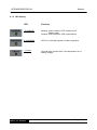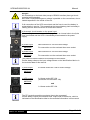
1
UPS Uninterruptible Power Supply MKD 2000 / 3000 XL Manual Item number: ACX11MKS2K0000XL ACX11MKS3K0000XL Version V1.1 May 2010 UPS MKD2000/3000 XL Manual Content 1 Presentation 4 2 2.1 Warranty conditions Limitation of liability 5 6 3 3.1 3.2 3.3 3.4 3.5 3.6 3.7 Safety General safety instruction Transport and storage Placement Connection Operation Handling batteries Maintenance, servicing and faults 7 7 7 7 8 8 9 10 4 Introduction 11 5 System description 12 6 6.1 6.1.1 6.1.2 6.1.3 6.2 6.3 Description of MKD series Handling elements on the front side LCD display Buttons LED display Elements on the back side Acoustic alert signs of the UPS 13 13 14 15 16 17 20 7 7.1 7.2 Storage and unpacking Storage of the UPS Unpacking the equipment 21 21 21 8 8.1 8.2 8.3 8.4 Installation and connecting of the UPS Connecting the UPS Communicational interface of the UPS Connection between UPS and battery pack Connection sequence 22 23 24 24 25 9 9.1 9.1.1 9.1.2 9.2 9.2.1 9.2.2 9.2.3 9.2.4 9.2.5 Operating and controlling the equipment Operating of the UPS Operating modes and signals Measured value display Instruction manual of the UPS Switching-on and starting the UPS Switching-off and power down the UPS Changing the basic setting Starting the testing mode Communication 26 26 26 29 30 30 31 31 33 33 10 Setting-up of the UPS 34 11 Troubleshooting 35 MKD XL Series Page 2 of 45 UPS MKD2000/3000 XL Manual 12 Software 37 13 13.1 13.2 13.3 13.4 13.5 Maintenance and service Measuring and autonomy time Replacing the batteries Service- log Service - hotline: Maintenance and service contracts 38 38 38 39 40 40 14 14.1 14.2 14.3 Technical data Specifications Scope of delivery / optional accessory List of wearing parts 41 41 42 43 15 Requirements for the declaration of conformity 44 MKD XL Series Page 3 of 45 UPS MKD2000/3000 XL Manual 1 Presentation In this instruction manual, the abbreviation UPS stands for Uninterruptible Power Supply. The following pictograms are used in this instruction manual: Denotes information which, if disregarded, poses a risk to health, functionality or safety. Warning about the handling of batteries. Warning about dangerous electrical voltage. Denotes additional information and tips. Recycling symbol. Denotes components that are governed by the electronic scrap ordinance. Denotes components or parts that must be disposed of in a specific manner. Never throw these components into the regular refuse. Copyright © 2004 All rights reserved. This instruction manual is protected by copyright law. The copyright owner is EFFEKTA Regeltechnik GmbH. Trademarks: All trademarks used are the property of their respective owners. EFFEKTA® is a registered trademark of EFFEKTA Regeltechnik GmbH. We reserve the right to make technical and visual changes, and we are not liable for typographical errors (E&OE). MKD XL Series Page 4 of 45 UPS MKD2000/3000 XL Manual 2 Warranty conditions The delivery receipt is considered to be the initial proof of purchase and should be stored carefully. It is required for all warranty claims. If the product is transferred to another user, then the latter is entitled to claim under the warranty for the remainder of the warranty period. The purchase receipt and this declaration should be transferred to the possession of the new owner. We guarantee that this equipment is in a functional state and corresponds in technical terms to the descriptions in the enclosed documentation. The warranty period for special equipment corresponds to the minimum period prescribed by legislation. This warranty is not valid for the following cases: Defects due to: damage during transportation, accidents, natural disasters, misuse, vandalism, inappropriate use, maintenance errors or incorrect repairs by third parties. Modifications, unauthorized tampering, incorrect operation, another device or accessory, incorrect installation, or any modification not approved by us. Disregard for the instructions in the supplied documentation. Incompatibility of the product as a result of technical innovations or regulations that may come into effect after the purchase. Incompatibility or malfunction caused by product components not used by us. Appearances associated with normal ageing of the product (wearing parts). Defects caused by external appliances. The warranty period for parts replaced and/or repaired within the scope of this warranty expires with the original warranty for the product. Equipment sent in without accessories will be replaced without accessories. Equipment returned will only be accepted if it is returned in the original packaging. Incidental transportation costs are generally excluded from the provisions of the warranty. MKD XL Series Page 5 of 45 UPS MKD2000/3000 XL Manual EFFEKTA GmbH does not give any express or implied warranties in relation to this equipment and its quality, performance, merchantability or suitability for a specific purpose. In some countries, the exclusion of implied warranties is not permitted by law. In this case, the validity of all express and implied warranties is restricted to the warranty period. When this period expires, all warranties cease to be valid. In some countries, a limitation of the validity period of implied warranties is not permitted by law, in which case the above restriction is not effective. 2.1 Limitation of liability Compensation claims are excluded unless they are based on deliberate acts or gross negligence of EFFEKTA GmbH or its employees. Liability under the Product Liability Act remains unaffected. Under no circumstances will we be held liable for: Claims for losses or damage made by third parties against you. Loss of or damage to your records or data or the cost of their recovery. Financial consequential damage (including loss of earnings or savings) or incidental damage, even in the event that we were informed of the possibility of such damage. Under no circumstances whatsoever will EFFEKTA GmbH be held responsible for any coincidental, indirect, special, consequential or other damage of any kind (including, without limitation, damage relating to loss of profit, discontinuation of business, loss of business information or any other loss) arising from use of the equipment or in any connection with the equipment, whether based on a contract, compensation, negligence, strict liability, or other claims, even if EFFEKTA GmbH was informed in advance about the possibility of such damage. This exclusion also applies for any liability arising from claims of third parties against the initial purchaser. In some countries, the exclusion or limitation of coincidental or consequential damage is not legally permitted, in which case the above declaration is not effective. MKD XL Series Page 6 of 45 UPS MKD2000/3000 XL Manual 3 Safety 3.1 General safety instruction Read and observe the user manual and safety instructions in this chapter before taking any further action (transportation, storage, connection, start-up etc.). Since the UPS equipment uses mains voltage and has a suitable energy accumulator (high-capacity batteries) installed either inside or outside the device, the instructions in this chapter are very important for all users and personnel. For this reason, appropriate safety instructions on the topic of batteries and battery packs are also dealt with here. When using external battery packs, you must also follow the safety instructions in the accompanying instruction manual. Work on the UPS equipment may only be performed by authorized technical personnel. 3.2 Transport and storage When storing equipment, make sure that it is also securely positioned. The equipment must not be transported or stored upside down. Position the equipment securely during transportation taking its centre of gravity into account. Due to its weight, UPS equipment with integrated batteries may drop suddenly if its position shifts slightly. When storing equipment, make sure that it is also securely positioned. 3.3 Placement The UPS is intended for use in ventilated rooms. During setup or installation, the installation location prescribed by the manufacturer must be observed. There is a risk of condensation where the UPS is exposed to extreme and rapid temperature changes. Before taking any further steps, the equipment should be allowed to acclimatize for at least 2 hours. Never set up or operate the equipment in a damp environment. Keep fluids away from the equipment. The UPS must not be set up near heat sources. Ensure that the vents of the equipment are not blocked and that the circulation of air is not impeded. MKD XL Series Page 7 of 45 UPS MKD2000/3000 XL Manual 3.4 Connection Only connect the UPS to an earthed shock-proof socket or, where a terminal clamp is used, be sure to connect the protective earth conductor. Under no circumstances should the equipment be operated without a protective earth conductor. The house installation socket must be easily accessible and located in the vicinity of the UPS. In the case of a fixed connection, ensure that the shortest possible cable lengths are used. In case of generator mode, there hast o be a polarized connection of the UPS. Only use VDE-tested and CE-labeled electrical cables to connect the consumer load to the UPS. In the case of a fixed connection to the consumer load, a suitable cable must be used. The fuse protection for the consumer load must always be installed directly in front of it, and never centrally in front of the UPS. Do not operate any household appliances and power tools, e.g. fan heaters, vacuum cleaners, drills, hairdryers, toasters etc., via the UPS. Do not connect any consumer loads to the UPS which could overload the equipment (e.g. laser printers). The sum of the earth fault currents of all consumer loads connected to the UPS must not exceed 3.5mA. Keep the connecting cables as short as possible and always lay these correctly. Avoid the dangers of laying connecting cables in locations where they may be tripped over, crushed or torn open etc. 3.5 Operation The mains power cable must never be disconnected during the operation of the UPS, otherwise the protective earthing of the UPS and the connected consumer loads will be lost. Before connecting consumer at the output, the basic configuration (9.2.3) has to be made. The output voltage with regard to the consumer and the output frequency during battery service are very important. The UPS equipment contains an energy accumulator (batteries). This means that the output of the UPS may be live even if it is not connected on the line side. To switch off the UPS completely, first press the switch on the front of the equipment (OFF position), wait until the UPS has switched off then disconnect the power supply (switch off the mains input externally or disconnect the UPS from the mains, e.g. by unplugging it). Make sure that no fluids or foreign bodies enter the UPS. MKD XL Series Page 8 of 45 UPS MKD2000/3000 XL Manual To protect the UPS, avoid constant load of the output over 80% (especially during battery service). The display of the output load is just supposed to be a reference value. Separate measurements are necessary to ascertain the exact output load. 3.6 Handling batteries Warning – danger of electric shocks and burns. Batteries can cause electric shocks and are capable of producing high shortcircuit currents which can also inflict burns. Unauthorized persons must be kept away from batteries. Do not place batteries against heat sources and do not throw them into a fire as they might explode! Do not open or destroy batteries. The electrolyte thereby released is extremely dangerous to persons and to the environment (danger of chemical burns to skin and eyes, toxic). Defective batteries must be disposed of in an environmentally-friendly manner Never throw batteries into the regular refuse. The local waste disposal regulations must be observed. MKD XL Series Page 9 of 45 UPS MKD2000/3000 XL Manual 3.7 Maintenance, servicing and faults Warning – danger of electric shocks. The UPS remains connected to the battery circuit even after it has been disconnected from the mains power supply and has a dangerous voltage potential. Therefore always disconnect the battery circuit before carrying out servicing or maintenance work and make sure that the equipment is isolated from the supply Work on batteries may only be performed and monitored by personnel with appropriate technical knowledge about the required precautions. Unauthorized persons must be kept away from batteries. When working on the UPS, the following precautions must be taken: Remove wristwatches, rings and other metallic objects Only use electrically-insulated tools The UPS must not be deconstructed. MKD XL Series Page 10 of 45 UPS MKD2000/3000 XL Manual 4 Introduction This manual is intended to provide basic information about single-phase offline UPS equipment, namely the functional principle, use of the various functions and the procedure to follow in the event of faults. In addition, this manual contains information on transportation and storage as well as handling and installation of the UPS equipment. The planning guidelines in this manual relate only to the specific requirements for UPS equipment. The national and local regulations for electrical installations must be followed without fail during installation. The contents of the description for this equipment may change as a result of technological developments. Though we have endeavoured to make these contents as accurate and clear as possible, we would be grateful for information on any errors which are noted. We accept no liability for errors in this description or their consequences. The purpose of UPS equipment (Uninterruptible Power Supply) is to protect sensitive electrical devices such as computers, workstations, electronic points of sale, mission-critical instruments, telecommunications equipment, process controls etc. from faults which may arise as a result of poor power supply quality or even power failures. Sensitive devices such as these require comprehensive protection against electrical faults. These may be external faults (e.g. bad weather, operating faults) or faults caused by adjacent devices (e.g. motors, air conditioning units, processing machines, welding equipment etc.). The power supply faults may be summarized as follows: o Fast and slow line-voltage spikes and fluctuations; o Mains power failure; o Fast and slow frequency spikes and fluctuations; o Mains heterodyning or transient voltages. The UPS equipment monitors the power supply parameters described above using suitable countermeasures to protect the connected users (e.g. changeover to support operation in the event of temporary over- or undervoltage to protect the end devices). MKD XL Series Page 11 of 45 UPS MKD2000/3000 XL Manual 5 System description The UPS is built following the principle of double conversion. The UPS supplies an uninterrupted, single-phase voltage to users with mission-critical applications. In addition to supplying consumer loads, the equipment also keeps its internal batteries in a fully charged state. In the event of a power failure or power fault (e.g. voltage fluctuation), the UPS continues, without interruption, to deliver a clean voltage supply to the UPS output. In support mode, the energy is drawn from the battery pack. Fig. 1: block diagram MKD series The block circuit diagram shows the individual modules of the equipment and provides a general impression of how they interact. If the mains power failure exceeds the autonomy time of the UPS, it shuts down to prevent deep discharging of the batteries. When the mains power supply is restored, the UPS restarts automatically, supplies the consumer loads and controls the charging of the battery pack. Outstanding performance characteristics oft he MHD Online UPS are: MKD XL Series o No interruptions or signal changes in case of primary mains failure. o Perfect sinus voltage on the output oft he UPS. The quality of the output voltage is much better than the mains voltage of the in-house network. o Processor controlled bypassing mode (bypass); o Power Factor correction on the input (>0,95); o High efficiency degree of the inverter >90% DC / AC; o High-performance communications interface (RS232 interface); o LCD displays status and operation mode Page 12 of 45 UPS MKD2000/3000 XL Manual 6 Description of MKD series In this chapter you will be confronted with the corresponding machine elements, get instructions for the handling and get information concerning the connectings of the UPS. 6.1 Handling elements on the front side Fig.. 2: display MKD series 6 5 1 7 4 3 2 All handling and display elements, which are necessary for normal service, are on the front side. MKD XL Series Page 13 of 45 UPS MKD2000/3000 XL Manual 6.1.1 LCD display Display 1) LCD display Function The LCD display indicates the service mode and several status figures. Following displays can be indicated by pushing the up and down button: o Actual status o INPUT VOLTAGE o OUTPUT VOLTAGE o INPUT FREQUENCY o OUTPUT FREQUENCY o BATTERY VOLTAGE o BATTERY CAPACITY o OUTPUT POWER (display of the load on the UPS output) o INSIDE TEMP. o NEW REC. o OLD REC. o Basic installations o model When the display light is off, it will be activated by pushing the first button. MKD XL Series Page 14 of 45 UPS MKD2000/3000 XL Manual 6.1.2 Buttons Buttons 2) Menu option Function The UPS will be started by pushing this button at the same time as the menu-down button (3) for about 3sec. The UPS switches over to testing operation by pushing this button at the same time as the menu-up button (4) for about 3sec. The acoustic alert can be stopped by pushing this button at the same time as the menu-up button (4) during battery backup mode (mains failure) 3) Menu-down (cursor key) The UPS will be started by pushing this button at the same time as the menu-option button (2) for about 3sec. The UPS will be switched-off by pushing this button at the same time as the menu-up button (4) for about 3sec. The menu (display) can be scrolled by pushing this button separately. 4) Menu-up (cursor key) The UPS will be switched-off by pushing this button at the same theme as the menu-up button (4) for about 3sec. The UPS switches over to testing operation by pushing this button at the same time as the menu-option button (2) for about 3sec. The menu (display) can be scrolled by pushing this button separately. Attention: if the „ON/OFF“ button is not pushed long enough, the UPS will not be switched-on /-off completely. If there is power supply over the fuse (assembly on the back side oft he UPS) the loading unit will still be active after the switch-off oft he UPS. MKD XL Series Page 15 of 45 UPS MKD2000/3000 XL Manual 6.1.3 LED display LED Function 5) NORMAL flashing: mains existent, UPS is switched-off (battery load) duration: mains existent, UPS is switched-on 6) WARNING UPS is in overload, bypass or battery operation. 7) FAULT General fault: inverter fault, over temperature or no battery voltage. MKD XL Series Page 16 of 45 UPS MKD2000/3000 XL Manual 6.2 Elements on the back side Fig. 3: back side view MKD2000 Fig. 4: back side view MKD3000 MKD XL Series Page 17 of 45 UPS MKD2000/3000 XL Manual Danger! All connectings on the back side (except of RS232-interface) have got circuit potential when attached. Also when uncoupled dangerous voltage is possible on the connections, due to loaded capacities in the inside oft he unit. If all connections of the UPS are existent and the fuse is used, the battery is automatically in service. This means that the internal battery pack is already in loading service without that the UPS has been started. a) Automatic circuit breaker on the power input: In case of high overcurrents or a fault (e.g. due to an internal short-circuit) the fuse is activated and the UPS is immediately disconnected to the power supply. b) Power input MKD2000 b) Power input MKD3000 Nema socket IEC 10A for mains voltage For connection use the enclosed three-core socket. Nema socket IEC 16A for mains voltage For connection use the enclosed three-core socket. The protective earth conductor must always be connected! Please always observe the input voltage shown on the identification label or in the technical data of this manual. c) UPS output 6 x Nema socket IEC 10A for mains voltage MKD2000 c) UPS output MKD3000 3 x Nema socket IEC 10A (Automatic circuit breaker 10A) and 1 x Nema socket IEC 16A The PE (protective earthing conductor) has to be connected ! Please always respect the indicated max. output load of the device, which is indicated on the identification-label or the technical information in this manual. MKD XL Series Page 18 of 45 UPS MKD2000/3000 XL Manual d) Communication (fuse D-Sub 9-jack) Via the serial interface (RS232), all of the relevant UPS data are transmitted to an appropriate primary control unit (e.g. PC). In addition, a defined shutdown signal can be sent to the UPS. Suitable software packages are available for this (see Software chapter). e) Socket for battery extension This socket interlinks the UPS with an optional available external battery pack, which increases the autonomy time. The confectioning has to be made with the supplied cord and during the UPS is switched-off. Get more information from the manual oft he external battery pack. As a precaution always compare before connectioning, the quoted voltage on the UPS as well as on the battery pack. Those values have to comply with each other. f) Slot for additional interfaces After removing the back panel, several extension possibilities can be used. e.g. optocoupler card; relay card; SNMP adapter or additional RS232 interfaces. g) RJ45 Overload protection for telephone, fax or modem h) Circuit Breaker The 3 x Nema socket IEC 10A from the UPS-Output is secured about a Fuse of 10A. only MKD3000 Identification MKD XL Series The identifications label contains information about: # Manufacturer # Equipment model and output class # Equipment input values # Equipment output values # Item number # Serial number # CE and barcode designation Page 19 of 45 UPS MKD2000/3000 XL Manual 6.3 Acoustic alert signs of the UPS Support mode and high battery capacity: The acoustic alert sounds in the following sequence (A) [beep -> long pause (4 s) -> beep-> ..., repeating]. Support mode and low battery capacity Normal operation and low battery capacity (battery LOW) Overload 100% - 125%: The acoustic alert sounds in the following sequence (B) [beep -> short pause (1 sec) -> beep -> ..., repeating]. Normal operation and overload 125% - 150%: The acoustic alert sounds in the following sequence (C) [beep -> short pause (0,5 sec.) -> beep -> ..., repeating]. Operating fault or overload >150%: The acoustic alert sounds in the following continuous tone, sequence (D) [beeeeeeeeeeeee....p]. Loading mode: mains is existent but the UPS is switched-off The acoustic alert sounds in the following sequence (E) [beep -> long pause (2 min.) -> beep -> ..., repeating]. MKD XL Series Page 20 of 45 UPS MKD2000/3000 XL Manual 7 Storage and unpacking 7.1 Storage of the UPS If the equipment is not installed immediately, the following should be observed: The equipment and accessories must always be left in the original packaging and stored. The recommended ambient storage temperatures are: +5°C...+30°C. Protect the equipment and its packaging from moisture. If the anticipated storage period is longer than 4 months, the UPS and external battery pack (optional) must be operated for a period of approx. 8 hours to prevent deep discharging of the batteries. 7.2 Unpacking the equipment Remove the shipping cartons and packaging material. Always store the equipment horizontally and never upside down. Check the shipping note to make sure that the delivery is complete. If the delivery is incomplete or incorrect, inform the supplier immediately. You should also check the delivery for transit damage. Any claims for transit damage must be made immediately: Retain the all shipping cartons and packaging material for verification purposes. Immediately inform the manufacturer or your supplier. Immediately inform the shipping company. MKD XL Series Page 21 of 45 UPS MKD2000/3000 XL Manual 8 Installation and connecting of the UPS All requirements in the technical data regarding environmental and operating conditions must be observed to ensure trouble-free functioning of the UPS. The following must be observed when setting up / installing the UPS equipment: Avoid extremes of temperature and atmospheric humidity. A maximum service life, particularly in relation to the batteries, is achieved at an ambient temperature of 15-25°C. Always ensure that sufficient space is available behind the UPS to make the necessary connections and, as the UPS is heavy, use suitable guide rails during installation. The load-bearing capacity of the support must be sufficient. Observe the specified installation location and only mount the equipment using the screw-in positions. Make sure that ventilation of the equipment is possible at all times. As this UPS is ventilated in a crosswise and lengthwise direction, a minimum clearance of at least 50mm between the UPS and the cabinet in which it is installed must be maintained at the sides as well as at the front and back. Ensure an appropriate flow channel. Make sure the equipment is arranged correctly. When installed in parent systems (e.g. machine, control cabinet), it must be ensured that the UPS operates within the specified temperature range. A sufficient level of forced ventilation must exist to remove excess heat that builds up in the space where the UPS is installed. MKD XL Series Page 22 of 45 UPS MKD2000/3000 XL Manual 8.1 Connecting the UPS The models of the MHD series are equipped with plug-type connections. The connection diagram (Fig. ) and the following information have to be observed: Fig. 5: connecting the UPS MKD S: 16A 1: 1.5 mm² Warning! The UPS equipment contains components with high voltage and amperage. Incorrect handling may therefore result in electrical accidents which may have fatal consequences or cause material damage. The protective earth conductor must always be connected! If not, the consumer loads will also not be earthed. In generator mode, the connection of the UPS hast o be polarized. Warning! The connection diagram shown in Fig. 5 only applies if: o the loop resistance is complied with up to the last consumer load; o the earthing of the consumer loads is ensured; o or that the consumer loads are separately protected against overcurrents and leakage currents, and are also earthed. Please note that if the UPS equipment is in an emergency OFF circuit and this is activated, power will still be supplied to the UPS output. The consumer loads will be supplied continuously for the duration of the support time. MKD XL Series Page 23 of 45 UPS MKD2000/3000 XL Manual 8.2 Communicational interface of the UPS A convenient communications interface is available that facilitates data exchange with the UPS. The connection should only be made using the cables specified in the “Accessories” chapter. When using the SNMP adapter, the communicational interface is switched-off. Fig. 6: Communicational interface of the UPS Assignment: Pin: 2 RS232 Receive data Rx or shut down SD 3 RS232 Transmit data Tx 5 RS232 GND The communicational interface is completely galvanically isolated. The UPS can also be forced to shut down immediately during support mode via the RS232 serial interface. This is triggered via a permanent +12V signal on receive data (Rx) (shutdown function). 8.3 Connection between UPS and battery pack Prior to the coupling of the UPS with the battery bank is to ensure that both units are switched off. Use only the accessories listed in the article. These include the compatible battery bank and a connection cable. Make sure that the output voltage of the battery bank is identical to the DC input voltage of your UPS. If this is not the case, the units are connected to each other under any circumstances. MKD XL Series Page 24 of 45 UPS MKD2000/3000 XL Manual Fig. 7 Rear view MKD1000 with Battery pack 8.4 Connection sequence Connect the UPS to the mains making sure that the mains and UPS are safely switched-off beforehand. Before connecting the consumer with the output, the basic configuration (9.2.3) has to be made. Connect the consumer load(s) to the UPS. Ensure that all consumer loads are switched off. MKD XL Series Page 25 of 45 UPS MKD2000/3000 XL Manual 9 Operating and controlling the equipment 9.1 Operating of the UPS There are different operating modes and operating messages of this UPS. 9.1.1 Operating modes and signals The most important modes of the UPS can be described as follows: Charging mode: If the mains power is available and the input fuse is switched on, the UPS is in charging mode. -> The batteries are already charged, but the UPS has not yet been switchedon. Depending on the basic setting there is no output voltage or the UPS is in bypass mode and there is output voltage. Display/alarm signals: The green LED (NORMAL) is flashing and the acoustic alert sounds in the following sequence (E) (beep -> long pause (2 min.) -> beep -> .., repeating). Without output voltage: With output voltage: Start-up mode: If the mains power is available, the start-up procedure is initiated when the two ON-buttons are pushed. Then the UPS switches for about 10 sec over to the bypassing mode. Afterwards the on-line mode is automatically activated. If no mains power is available during the start-up procedure, the UPS switches directly to bypass mode directly after the start-up procedure. Display/alarm signal: The yellow LED (WARNING) lights up during bypass mode, the acoustic alert resounds 2 times shortly. Bypass mode: MKD XL Series Page 26 of 45 UPS MKD2000/3000 XL On-line mode: Manual If mains power is available and the UPS has completed the start-up procedure, on-line mode is automatically activated. -> If necessary, the battery pack is also charged in this operating mode. Display/alarm signal: Just the green LED (NORMAL) is flashing continuously, no acoustic signal. On-line mode: Battery backup mode: If the mains power fails, the UPS switches immediately over to support mode. Display/alarm signal: The yellow LED (WARNING) lights up. The acoustic alert sounds in the following sequence (A); (beep -> long pause (4 sec.) -> beep -> ..., repeating). In case of excess of the battery low limit, the acoustic alert sounds in the following sequence (B); (beep -> short pause (1 sec.) -> beep -> ..., repeating). battery mode: MKD XL Series Page 27 of 45 UPS MKD2000/3000 XL Testing service: Manual If the UPS is connected with the mains, testing service can be conducted by pushing at the same time for about 3sec button (2) “Menu option” and button (4) “Menu-up”. During this process, after a LED-text, the UPS switches for about 10sec over to battery service. Display/alarm signal: Red LED (FAULT) yellow LED (WARNING) green LED (NORMAL). Display „BAT INVERTER“ and yellow LED (WARNING) for about. 10sec. No acoustic alert. Overloadin g service: If there is overload at the UPS output, depending on overload the UPS switches over to bypassing service, after max. 30sec. With the button 3 “Menu-down” (push it 8 times), you can switch over to overloading display. (block figure, see fault mode) Display/alarm signal, before switching over:: Green LED (NORMAL) and the yellow LED (WARNING) are glowing; Acoustic alert sounds in the following sequence (A); (beep -> long pause (4 sec.) -> beep -> ..., repeating). Display/alarm signal, after switching over to bypassing mode: only the yellow LED (WARNING) is glowing; acoustic alert sounds in a continuous tone, sequence (D). e.g. output load of 55% (reference value) Fault mode: If there is a fault, the UPS switches immediately over to bypassing mode. Fault mode can be released by overload, short circuit on the UPS output, overheating, inverter-fault or DC/BUS-fault. Display/alarm signal in bypassing mode: In case of overload, the yellow LED (WARNING is glowing; In case of overheating, inverter- or DC/BUS- fault, the red LED (FAULT) is glowing; the acoustic alert sounds in a continuous tone, sequenceing mode (D). MKD XL Series Page 28 of 45 UPS MKD2000/3000 XL Manual Bypassing mode: 9.1.2 Measured value display Display: By pushing the buttons (3) „Menu-down“ and (4) „Menu-up“ you can switch over to the following displays: INPUT VOLTAGE OUTPUT VOLTAGE INPUT FREQUENCY OUTPUT FREQUENCY BATTERY VOLTAGE BATTERY CAPACITY OUTPUT POWER INSIDE TEMP NEW REC. OLD REC. MKD XL Series Page 29 of 45 UPS MKD2000/3000 XL Manual Basic setting Type After about 2 min. it is automatically switching over to the status display. 9.2 Instruction manual of the UPS The user of the UPS always has to respect the instructions of this manual. The user is only allowed to do the following instructions very carefully: o Using of the handling elements: switch-on, start and switch-off the UPS. o Reading the display elements and interpreting the acoustic alerts. o Starting the testing service. o Using of the communicating interfaces, whereas in case of UPS installation with permanent connection, the connection to PC or other systems has to exist. Due to extensive protection functions which the UPS ensures to its connected machines, the UPS is working completely automatically. Just the switching-on and the starting or the switching-off has to be activated manually. Furthermore there can be made a data exchange by using the communicating interface or the SNMP-adapter which is not forceful necessary for the general operation of the UPS. 9.2.1 Switching-on and starting the UPS To switch the UPS on, connect it to the power supply by plugging-in the line cord. Ensure that the mains fuse (back side of the unit) is activated. Before starting the UPS for the first time, the basic setting (9.2.3) has to be checked. The UPS will be started by pushing at the same time the buttons (2) “Menuoption” and (3) “Menu-down” for about 3sec. After the starting procedure, the UPS switches-over to the corresponding operation mode. MKD XL Series Page 30 of 45 UPS MKD2000/3000 XL Manual 9.2.2 Switching-off and power down the UPS To switch the UPS off, the buttons (3) “Menu-down” and (4) “Menu-up” have to be pushed for about 3sec at the same time. At the same time the UPS will be in loading-service to keep the accumulators loaded and ready for service. To achieve a completely disconnection of the UPS, the line cord of the unit has to be plugged-out. 9.2.3 Changing the basic setting Before changing basic settings, you should observe the following points: Basic settings: o False settings can damage the UPS or the consumer loads. o Be informed about the technical data of the connected consumer loads. o All consumer must be disconnected to the charge output. o Ensure that the UPS is switched-off. o The new settings will first be adopted after a complete new start of the UPS (switching-off, disconnect the line cord and then connect it again). Following parameter can be changed in te basic settings: Switching threshold for the bypassing mode (lower switching threshold 176V +/-20V; upper switching threshold 253 +/-20V). Output voltage (210V; 220V; 230V; 240V AC). Output frequency (50Hz; 60Hz) in battery service; input frequency has to be adapted. Active or inactive bypass in switched-off condition (inactive = xxHz; active = xxHz P). In switched-off condition, scroll with the button (3) “Menu-down” over to the display BYPASS LIMIT SET. Now the curser can be set to LO or HI by pushing the button (2) “Menu option”. Voltage threshold for the bypass can be changed by pushing the button (3) „Menu-down“. MKD XL Series Page 31 of 45 UPS MKD2000/3000 XL Manual BYPASS LIMIT SET (input voltag) Scroll in switched-off condition, with the button (3) “Menu-down” to the display OUTPUT V&F. The cursor can be set to Vac (output voltage) or Hz (output frequency) by using the button (2) “Menu-option”. In switched-off condition, output voltage or output frequency can be changed by using the buttons (3) “Menu-down” and (4) “Menu-up”. OUTPUT (e.g. 230VAC; 50Hz inactive bypass) Output frequency can have the following settings: 50Hz output frequency 50Hz; inactive bypass 60Hz output frequency 50Hz; inactive bypass 50Hz P output frequency 50Hz; active bypass 60Hz P output frequency 50Hz; active bypass Confirm your choice with button (2) „Menu-option“. By using the cursor buttons (3+4) the wanted storage can be chosen in case of a savety query. Confirm with the button (2) “Menu-option”. Safety query Choice with cursor MKD XL Series Page 32 of 45 UPS MKD2000/3000 XL Manual 9.2.4 Starting the testing mode Before activating the testing service, you should consider following information: o Inform involved users about your action. o As a precaution save all data of the connected machines. o Let all connected machines switched-on, so that the loading conduct can remain. o Ensure that the UPS is in power supply mode. Push for about 3sec the buttons (2) “Menu-option” and (4) “Menu-up” to switch over into testing service. This operation mode is just a function test of the UPS. In this moment the display of the accumulator capacity is just a measurement of the loading condition of the battery pack. It is not the indication of the total battery backup capacity. 9.2.5 Communication Corresponding software packages are necessary for data exchange between the UPS and the superior system. The product range you can see in chapter „Software“. MKD XL Series Page 33 of 45 UPS MKD2000/3000 XL Manual 10 Setting-up of the UPS To guarantee a perfect setting-up, please follow the instructions: 1. Connect the UPS with the mains, by using the enclosed cord. 2. Wait until the system test is finished. 3. Switch the UPS on by using the buttons as already described. 4. Wait until the UPS is in power supply mode. 5. Now start to connect the consumer loads successively and observe the load display. If all steps have been made, the UPS has to be now in the power supply mode and the load display should indicate less than 100 %. 6. Switch the UPS off (button combination OFF). 7. Wait some seconds („refresh“). 8. Start the UPS again (button combination ON). After 10 seconds the UPS should be in the power supply mode. This test ensures that the system also starts with connected total load. Now the UPS can remain ready in this condition. MKD XL Series Page 34 of 45 UPS MKD2000/3000 XL Manual 11 Troubleshooting Just authorized persons are allowed to do troubleshooting at the UPS. If failures occur during UPS service, try to solve the problem by following the below mentioned schedule: Problem Possible reason solution No function, The UPS has got no power supply or is not switched-on. Assure that all connections are correct and confirm this by corresponding voltage measurements. Switch the fuse of the UPS on. The UPS cannot be started, no warning message. The ON buttons have not been pushed long enough. Push the ON buttons for about 23sec. The UPS is in bypass mode. The “fault” LED is glowing, the display shows “Overload fault”, acoustic alert sounds The UPS is overloaded with regard to the connected machines Disconnect the connected machines or a part of it from the UPS until the load display indicates <= 100 %. The UPS is in bypass mode. The fault LED is glowing; the display shows “Temp. fault”, acoustic alert sounds The internal temperature of the UPS is too high Switch off the UPS, disconnect the connected machines and call the customer service The UPS is in bypass mode. The fault LED is glowing; the display shows “Inverter fault”, acoustic alert sounds The inverter of the UPS is not operational Switch off the UPS, disconnect the connected machines and call the customer service The UPS is in bypass mode. The fault LED is glowing; the display shows “DC_BUS fault”, acoustic alert sounds The DC bus of the UPS is not operational Switch off the UPS, disconnect the connected machines and call the customer service no display, no warning message. MKD XL Series Page 35 of 45 UPS MKD2000/3000 XL Manual Autonomy time is lower than nominal. The accumulators are not completely loaded or particular accumulators are defective. Load the accumulators longer than 8 hours and continue the test. If the problem remains, the accumulators have to be exchanged. The UPS is ok but the connected machine does not work. The connection between UPS and the machine is defective. Check the connection and confirm it by voltage measurement. If your failure notice of the UPS is not mentioned in this schedule, please contact our service department and keep this information ready: 1. model number, item number; 2. date of the day, when the problem occurred; 3. detailed description of the problem; MKD XL Series Page 36 of 45 UPS MKD2000/3000 XL Manual 12 Software By an adequate software package, installations and service conditions of the UPS can be detected and handled by using the communication interfaces. The software packages are available over the producer / supplier or over the mentioned service-hotline (chapter „Service“). There you get necessary information about adequate software packages with regard to your application and UPS. Also see our website: http://www.effekta.com/ The following basic functions are supported by all software packages: o Capture and display of the mains condition of the UPS; o Display of the UPS output condition; o Capture and display of the loading condition of the battery pack; o Closing of opened applications in case of power failures; o Shut down of the operating system; o Issue of protocol data; o General control of the UPS-data and conditions (diagnosis-function); o More information about the several software packages like installation, handling and performance you get from the software instruction. In chapter “Accessories” you can find an adequate and tested software package.. MKD XL Series Page 37 of 45 UPS MKD2000/3000 XL Manual 13 Maintenance and service You can expect a long service life and trouble-free operation from your UPS equipment as long as you ensure that the necessary minimum level of maintenance is carried out. However, the reliability of the UPS is also significantly affected by environmental conditions. The temperature and atmospheric humidity of the surroundings must be kept within the limits. In addition, the area around the UPS must be kept as clean and free of dust as possible. At the ideal ambient temperature of 22°C, the typical service life of the batteries is approx. 4 years, but this service life can be substantially increased (to approx. 8-10 years) by using special batteries. You should check at regular intervals (every 6-12 months) to ensure that the remaining bridging time is sufficient for your intended purposes. If this is not the case, then it is time to replace the batteries. 13.1 Measuring and autonomy time Before starting this procedure, it is absolutely necessary to save all open data. Also inform all employees concerned. There are essentially two methods of measuring the autonomy time. Method a) is suitable for measuring the actual autonomy time, whereby the consumer loads will inevitably have zero current at the end of the bridging time. Method b) enables the residual capacity to be determined after a specific autonomy time, whereby consumer loads will not generally be left with zero current. To apply one of the named methods, force the UPS into support mode by switching off the mains power supply. After performing the measurement, switch the mains power supply back on and start the UPS as normally using the buttons “ON”. Bear in mind that after the measurement the batteries will be discharged, i.e. the on-line/charging mode must have been active in the UPS equipment for several hours (min. 5 hours) before they are approx. 80% operational again. If the support time is not measured due to local conditions or directives, we recommend replacing the batteries every two years as a preventive measure to avoid the risk of inadequate support time due to battery deterioration. 13.2 Replacing the batteries Before you proceed, take the safety information provided into consideration. Carry out the work in the specified sequence. Always use safety tools. Before you start work, make sure that the UPS is switched off and is disconnected from the mains power supply. MKD XL Series Page 38 of 45 UPS MKD2000/3000 XL Manual Work on the battery pack may only be carried out by technical personnel who have received specific training in the handling of batteries Note that high voltages remain in the equipment even when it is switched off. This includes the voltage in the battery pack and the charging voltages in mains capacitors, for example. Appropriate safety measures must be taken to prevent electric shock. Owing to the dangers described above, no further details are provided in this manual on the replacement of batteries. On demand technical personnel can receive a separate description. 13.3 Service- log Please always inscribe hereunder every maintenance or service work on the UPS. Date: MKD XL Series Work carried out: Carried out by: Page 39 of 45 UPS MKD2000/3000 XL Manual 13.4 Service - hotline: In the unfortunate event that problems occur with the UPS or if you require safety-relevant information, please contact our service hotline on the following phone or fax numbers: Tel. no.: 0049 / (0) 741–17451-0 Fax no.: 0049 / (0) 741–17451-29 If it is not possible for you to get in touch by telephone, we have set up an email contact address for you: [email protected] In addition, you can contact the department or subsidiary you need directly via the following Internet address: http://www.effekta.com/html/kontakt.html 13.5 Maintenance and service contracts EFFEKTA Regeltechnik GmbH offers you tailored maintenance and customer services that ensure the highest possible reliability and availability of your UPS equipment. In addition, as part of a maintenance contract, our expert technical personnel can provide you with support in the following areas: o Regular checking of the equipment, especially the batteries, as well as timely replacement and disposal of batteries; o Checking of the UPS installation; o Disposal of defective or deteriorated components; o Eco-friendly disposal of batteries. Our entire range of service is presented at: http://www.effekta.com/html/service.html Or alternatively, you can contact us directly at the above mentioned addresses. MKD XL Series Page 40 of 45 UPS MKD2000/3000 XL Manual 14 Technical data 14.1 Specifications Model: Power: Mains inpu: Phases MKD2000 XL MKD3000 XL 2000 VA / 1400 W 3000 VA / 2100 W 1 external conductor + neutral conductor Voltage window 160 – 300 V AC Bypassing area 176 – 253 +/-20V AC Nominal frequency 50 / 60 Hz Power factor UPS output: Nominal voltage Power output max. Voltage regulation Frequency tolerance > 95 % 230 V AC (sinus) 8.7 A +/- 2 % (statically) +/- 0.5 % (battery service) Overload 105 ... 150 % für 30 s, > 150 % für 200ms Autonomy time ca. 7 min (normal conditions) Efficiency factor: DC -> AC DC-input Input voltage Interface: RS232 Environment: Allowed temperature 96 V DC (nominal) 0 ... + 40 °C +15 ...+ 25 °C 0 ... +40 °C 20 ... 90 % (non condensing) Standards: EN 50091-2 Technology non-stop service, double-converter with autom. bypass switch. Cooling Fan cooling Acoustic level Weight Inspections Dimensions: MKD XL Series 96 V DC (nominal) D-SUB socket 9-pol (galvanically separated) Storage temp. Rel. air humidity ca. 6 min (normal conditions) > 90 % Suggested temp. Generally: 13 A h x w x d [mm] < 50 dB 34.0 kg 35.0 kg CE 352 x 200 x 450 mm 352 x 200 x 450 mm Page 41 of 45 UPS MKD2000/3000 XL Manual 14.2 Scope of delivery / optional accessory Below is a list of components that have been specifically tested and approved for this UPS by EFFEKTA Regeltechnik GmbH (Please examine the completeness of the scope of delivery after receipt of the product immediately): Accessory: 1x function / view: Item number: UPS-electronics incl. internal batteries *** X Rear view 2000 VA rear view 3000 VA 1x Manual Printed manual English 1x Software bundle „PowerShut Plus“ CD-ROM with Network compatible UPS management and monitoring software X LAN-PowerShut X M2505 (1:1) X 1 License Windows/Novell 1 License UNIX, LINUX, MAC 1 License RCCMD (Network Remote Client) 1x LAN/RS232- Interface connection cable connection 1x Connection cable X 2000VA with 10A IEC (straight, 140mm) 2000VA with 10A IEC (straight, 170mm) 1x MKD XL Series Output cable 10A IEC (straight, 140mm) X Page 42 of 45 UPS MKD2000/3000 XL *** Manual USB slot Extension card for USB interface Z0P/USB O Relays slot Extension card for relays outputs Z0P/AS400 O Opto-coupler Extension card for opto-coupler output Z0P/DB9 O SNMP-Mini-Slot Extension card for network interface GE/32CS121MINI O X = scope of delivery / O = can be ordered separately as an option 14.3 List of wearing parts The following components are subject to normal wear and tear and are therefore not covered by the warranty for this UPS: Wearing part: Function: Item number: XXXX XX XX ** Energy storage Depending on equipment, see accessories or on demand battery 12 V xx Ah ________ ** For wearing parts designation, see fitted batteries. This can also be obtained on request. MKD XL Series Page 43 of 45 UPS MKD2000/3000 XL Manual 15 Requirements for the declaration of conformity CE-labeled UPS equipment complies with the following harmonized standards and EC guidelines: EU-guideline: 73/23/EEC (for devices operating within a restricted voltage range)) 93/&(EEC as a supplement to guideline 73/23/EEC 89/336/EEC as a supplement to guideline on electromagnetic compatibility 92/31/EEC as a supplement to guideline EMV 89/336/EEC Standards: EN 50091-2 EN 61000-3-2 EN 61000-3-2 EN 62040-1-1 An EU declaration of conformity for CE-labeled products can be requested from the following address: EFFEKTA Regeltechnik GmbH Rheinwaldstr. 34 78628 Rottweil GERMANY Tel.-no.: 0049 / (0) 741–17451-0 HB_EN_ABX11MKS2K03K000000_081111.doc MKD XL Series Page 44 of 45 UPS MKD2000/3000 XL MKD XL Series Manual Page 45 of 45