1
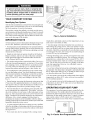
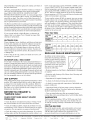
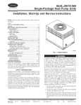
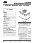
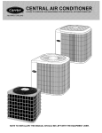
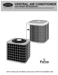
HEATING
&COOLING
50JS, JX
Heat Pump
Single-Packaged
Visit www. carrier, co i1"1
A GuideTo Operating and MaintainingYour
Single-Package
WELCOME TO EFFICIENT
YEAR-ROUND COMFORT
Understand the signal words DANGER, WARNING, and
CAUTION. These words are used with the safety-alert symbol.
DANGER identifies the lnost serious hazards whichwill result
in severe personal inju W or death. WARNING signifies hazards
which could result in personal injury or death. CAUTION is
used to identify unsafe practices whichwould result in lninor
personal iNury or product and property damage. NOTE is used
to highlight suggestions which will result in enhanced installation,
reliability, or operation.
Congratulations on your excellent choice and sound investment in year-round home COlnfort!
Your new heat pump represents both the latest in engineering
developlnent and the culmination of ma W years of experience
fFolri one of the most reputable lnanufacturers of comfort
systems.
Your new unit is alnong the most energy-et_cient and reliable
heat pump products available today. To assure its dependability, spend just a few lninutes with this booklet now. Learn abom
the operation of your heat pump, and the small amount of maintenance it takes to keep it operating at its peak ei_ciency.
Improper installation, adjustment, alteration, service, maintenance, or use can cause explosion,
fire, electrical shock, or other conditions which
may cause serious injury, death or property damage. Consult a qualified installer, service agency,
or your distributor or branch for information or assistance. The qualified installer or agency must
use factory-authorized
kits or accessories when
modifying this product.
With minimal care, your new heat pump will provide you
with year-round
home or oi_ce comfort_oth
now and for
years to come.
SAFETY CONSIDERATIONS
Recognize safety information. This is the safety-alert symbol
z_. When you see this symbol on the unit and in instructions
or manuals, be alert to the potential for personal injury.
NOTE TO INSTALLER:
THIS MANUAL
SHOULD
Fig. 1--50JS/JX
Maeufacturer
Book 1 1
Tab
lb 5a
reserves
PC 101
the right
to discontinue,
Catalog No. 535-00084
or change
Heat Pump Unit
THE EQUIPMENT
USER.
Unit
at any time, specifications
Printed in USA.
BE LEFTWITH
1/03
or designs
Form
without
OM50-34
notice
and without
Pg 1
incurrieg
Replaces:
obligations.
OM50-26
To prevent serious injury, death, or property damage, read and follow all instructions and warnings,
including labels shipped with or attached to unit
before operating your new heat pump.
YOUR COMFORT
Identifying
SYSTEM
Your System
Take the time to thmiliarize yourself with your packaged heat
pump system. This knowledge will be of use in understauding
the basic operation of your new heat pump.
The unit has a rating plate affixed to it which provides necessary inforlnation for specific identification of a unit. You should
familiarize yourself with the product, model, and serial numbers listed on each rating plate. Record theln for fimtre reference on the last page of this booklet.
IMPORTANT
FACTS
To better protect your investlnent and to eliminate unnecessary
service calls, familiarize yourself with the following facts:
• Your heat pump system should never be operated without a
clean air filter properly installed. Plau to inspect the filter periodically. A clogged air filter will increase operating costs aud
shorten the life of the unit.
• Supply-air and return-air registers should not be blocked.
Drapes, filrnimre, aud toys are some of the items colnlnonly
found obstructing registers. Restricted airflow lessens the
unit's efficiency aud life spau.
• The outdoor unit must have unrestricted airflow. Do not cover the unit, lean anything against it, or stand on it. Do not allow
grass clippings, leaves, or other debris m accumulate around
or on top of the unit. Maintain a 12-in. lninilnum clearance
between the outdoor unit and tall grass, vines, shrubs, etc.
• Your lmdtipurpose indoor thermostat is the control center
for your heat pump system. You should t:amiliarize yourself
with its proper operation. Attempting to control the system by
other means
for instauce, switching the electrical supply
power ON aM OFF may cause damage to the unit. (See
Fig. 3.)
• During heating, increasing the therlnostat setting more than
2° may cause the supplelnental heaters to be turned on for a
short period of time to satisfy the therlnostat. Needless use of
the supplelnentary heat reduces potential energy savings.
• You may find that you can lnaintain greater personal coinfort by running the fan continuously. "Air pockets" can forln
due to the structure of your home or office, placelnent of registers, etc. These air pockets may be too cool or warm for your
liking. Continuous thn operation minimizes any telnperature
differences. Also, systems equipped with electronic or
lnechanical air cleaners aud/or humidifiers offer the added
benefits of having the air continuously cleaued year-round aud
humidified during the winter season.
Fig. 2mTypical
Installation
which allows individtml control over the telnperatures of separate areas of your home or office.
• Your heat pulnp will relnove hulnidity from your home or
office during the cooling season. After a few lniumes of operation, you should be able m see water triclde froln the condensate drain. Check this occasionally to be sure the drain system
is not clogged. Of course, don't expect to see much drainage if
you live in a very dry enviromnent.
• During the heating cycle, air from your registers may seem
cooler thau you might first expect. This is because your heat
pump delivers a constaut flow of air at around 90°F to 105°F
instead of sudden bursts of hot air as with a conventional fitrnace. This air lnay feel cool because it is slightly cooler thau
your skin telnperature. However, it is sufficiently warm to
keep you COlnfortable.
• Ice or ti_ostwill tend to forln on the coil during the wiuter heating operation. Your heat pump is designed to atttomatically melt
the ice. When in this defrost cycle, it is norlnal for steam or fog to
rise froln the outdoor unit. Do not be alarmed!
• Do not operate your unit in the cooling mode when omdoor
telnperatures
are below 40°F unless your unit was modified
for low-alnbient
operation.
• Do not operate your unit in the heating mode when outdoor
telnperatures
are above 66°F unless you set your therlnostat
to emergency heat lnode.
OPERATING YOUR HEAT PUMP
The operation of your heat pump system is controlled by the
indoor therlnostat. You simply adjust the therlnostat and it
maintains the indoor telnperature at the level you select. Most
therlnostats for heat pump systems have 3 controls: a temperature control selector, a FAN control, and a SYSTEM or
MODE control. Refer to your T-stat owner's lnauual for more
inforlnation.
• A system equipped with a heat or energy recovery ventilator
offers the advantage of exhausting stale air [}o111your home or
office and allowing fresh air in from the outdoors while minimizing heat loss.
• Your system may also be equipped with a zoning system
Fig. 3mCarrier
Non-Programmable
T-stat
COOLING
MODE
When operating in cooling mode, your heat pump will run in
cooling lnode until the indoor telnperature is lowered to the
level you have selected. Chaextremely hot days, your heat
pump will run for longer periods at a time and have shorter
"ofF' periods than on moderate days.
The following are typical conditions that add extra heat and/or
humidity to your holne or office. Your heat pump will work
longer to keep your home or office COlnfortable under these
conditions:
EMERGENCY
HEAT MODE
This allows your supplelnental heating source to keep your
home or office warm until your heat pump can be serviced. Also,
if the electricity to your heat pump has been off for lnore than
30 lninutes, switch your therlnostat to EHEAT lnode before
restarting your heat pump. Leave the system in EHEAT lnode
for an alnount of time equal to the power outage. It is not necessary to exceed 12 hrs. (If your camaot deterlnine how long the
power has been oft', leave the system in EHEAT mode for 8 hrs.)
• Entrance doors are frequently opened and closed
• Laundry appliances are being operated
MAIN
• A shower is running
ON
• More than the ustml number of people are present in the holne or
Office
• More than the normal nulnber of electric lights are in use
• Drapes are open on the SUlmy side of the home or office
HEATING
MODE
OFF
With the SYSTEM or MODE control of your indoor therlnostar set to HEAT, your heat pulnp will run in heating lnode until
room telnperature is raised to the level you have selected. Of
course, your heat pulnp will have to operate for longer periods
to lnaintain a COlnfortable environlnent on cooler days and
nights than on moderate ones.
Fig. 4_Main
SUPPLEMENTAL
Your heat pump is your primary heating source. Your system
may also be equipped with a supplelnental heating source such
as electric heat. On cold days and nights, your system will automatically turn on the supplelnental heat in order to lnaintain
the level of COlnfort you have selected.
When your heat pulnp needs additional heat to keep you coinfortable, your Carrier electronic therlnostat will turn on the
supplelnental heat (if equipped) and will display the 'AUX
HT" message.
DEFROST
Electrical
Disconnect
HEAT
PERFORMING ROUTINE
MAINTENANCE
With the proper lnaintenance and care, your heat pump will
operate economically and dependably. Maintenance can be
accomplished easily by referring to the following directions.
However, before perforlning lnaintenance, consider these
ilnportant safety precautions:
MODE
When your heat pump is providing heat to your holne or office and
the outdoor temperature drops below 45°F, lnoisture lnay begin to
freeze on the surthce of the coil. If allowed m build up, this ice would
impede airflow across the cN1 and reduce the amount of heat
absorbed from the outside air. So, to maintaha eneigy-efficient
operation, your heat pump has an autolnatic defrost lntxte.
The defrost lnode starts at a preset time intelwal of 90 lninutes,
although, it may be reset to either 30 or 50 lninutes. Defrost
will start at the preset time only if the ice is sufficient to interfere with norlnal heating operation.
After the ice is melted from the coil, or after a maxinaum of 10
lninutes in defrost mode, the unit amomatically switches back
to normal heating operation.
Disconnect all electrical power to the indoor air handler or furnace before removing access panels to perform any maintenance. Disconnect power to the unit.
Note: There may be more than 1 electrical disconnect
switch. Electrical shock could cause severe injury or
death.
Although special care has been taken to minimize
sharp edges in the construction of your unit, be extremely careful when handling parts or reaching into
the unit.
Do not be alarmed if steam or fog appears at the outdoor unit
during defrost mode. Water vapor froln the melting ice may
condense into a mist in the cold omside air.
CHECKTHE
During certain weather conditions such as heavy snow and
freezing rain it is not uncolnmon for ice to build up on the unit
grille. This is normal for these weather conditions. Do not
attempt to relnove the ice from the unit grille. This condition
will not affect the proper function of the unit and will clear
within a few days.
A dirty air filter will cause excessive strain on the COlnpressor
and blower motor. This can cause the COlnponents to over-heat
and autolnatically shut down. In the worst case, the components will tail and need to be replaced. To avoid inefficient or
failed operation of your unit, CHECK THE FILTER(S)
EVERY 3 TO 4 WEEKS. Replace filter(s) when necessary, or
clean the filter(s) if you have the reusable type.
AIR FILTER
Disposable
filtersshould
bereplaced
bysimilar,newfiltersof
below room telnperamre and the SYSTEM or MODE control
thesamedimensions.
is set to COOL or AUTO. If you require warlnth, lnake sure
that the temperature control selector is set above room temperReusable,
perlnanent
filtersshould
bewashed
in asolution
of
ature and the SYSTEM or MODE control is set to HEAT or
coldwaterandmilddetergent,
thenrinsedandthoroughly
AUTO. The FAN control should be set to ON for continuous
dried.THEFILTERMUSTBECOMPLETELY
DRY
BEFORE
BEINGREINSTALLED.
Toavoidprolonged
shut- blower operation or AUTO if you wish blower to function only
downofyourunitwhileafilterisdrying,youshould
havean while your heat pulnp is operating.
extrafilteronhand.Thisallowsyoutorotatebetween
the2
If your COlnfort system still tails to operate, turn your system
withlninilnaldowntilne
foryourCOlnfort
system.
Extrafilters off and contact your servicing dealer for troubleshooting and
maybepurchased
frolnyourdealer.
repairs. Specify your apparent problem, and state the lnodel
Thefilters(s)
andfilterrackforapackaged
system
aresupplied and serial number of your equiplnent. (You should have theln
andinstalled
bythecontractor
ordealer.
Typically,
thefilter(s)
and recorded on the last page of this booldet.) With this inforlnarackarelocated
inthereturn-air
ductattheoutdoor
unitorbehind tion, your dealer may be able to offer helpful suggestions over
phone or save vahmble time tl_ough knowledgeable prepthereturn-air
grille(s).
Have
yourdealer
show
youthelocation
of the
aration for the service call.
yourfilter(s)andtheprocedures
forrelnoval
andreplacement.
Filter Size Table
If yoursystem
includes
ahighefficiency
or electronic
air
cleaner,
refertoaircleaner
User'sManualforproperfilter
UNIT SIZE
50JX
024
030
036
042
048
060
cleaning
orreplacelnent.
OUTDOOR
RETURN-AIR
FILTERS (in.)
COIL
It"grass clippings, leaves, shrubbery, and debris are kept away
from the unit, lninilnal care should be sufficient to keep the
system functioning properly. However, if the outdoor coil
becomes dirty, use a vacuum cleaner or shop vac with soft
brush attachlnent to clean the exterior surface. X_Sacuumcoil
surface using an up and down motion. Be carefid not to bend
or damage fins.
If dirt is deep in the coil, contact your dealer for service. Do
not attempt this yourself.
OUTDOOR
20x20
20x20
20x24
24x30
24x30
COILmSEA
COAST
It"your unit is located near the ocean, special lnaintenance is
required. Ocean mist/breeze carries salt, which is corrosive to
most metals. Although your new unit is made out of galvanized
metal and is protected by top-grade paint, you should take the
precaution of additional lnaintenance which consists of periodically washing the unit. By washing all exposed surfaces and
coil, you will be adding additional life to your unit. Please consult your installing contractor for proper intervals/procedures
for your geographic area or service contact.
UNIT SIZE
50JS
RETURN-AIR
FILTERS (in.)
Throwaway
018
024
030
036
042
20x20
20x20
20x20
20x24
24x30
REGULAR
048
DEALER MAINTENANCE
In addition to the routine lnaintenance that you perforln, your home
comfort system should be inspected regularly by a properly trained
service technician. The inspection
(preferably twice each year, but at
least once every year) should
include the following:
• Routine inspection of air filter(s). Re _lacement or cleaning
as required.
• Inspection and cleaning of the blower wheel, housing, and
motor as required.
UNIT SUPPORT
• Inspection and, if required, cleanh_g of coils.
• A check of all electrical wiring and connections.
BEFOREYOU REQUEST
"SERVICE CALL"
CHECK FORTHESE
PROBLEMS:
A
EASILY SOLVED
• Check the settings on your indoor therlnostat. If you desire
cooling, make sure that the telnperature control selector is set
reserves
the right to discontinue,
Catalog No. 535-00084
• Operational check of the heat pulnp system to determine
actual working condition. Necessary repair and/or adjustment
should be perforlned at this time.
WARRANTIES
• Check for sufficiem airflow. Check the air filter(s) for aW
accumulations of dirt. Check for blocked return-air or supplyair registers. Be sure registers are open and unobstructed.
PC 101
• A check for secure physical connections of individual coinponents within unit.
• Your servicing dealer may offer an econolnical service
contract that covers seasonal inspections. Ask for fimher details.
• Check the indoor and omdoor disconnect switches. Verify
that circuit breakers are ON or that filses have not blown.
Manufacturer
060
24x3024x30
Your packaged heat pulnp unit should be maintained at a level
position. If its support should shift or settle so that the unit is
no longer level, you should correct the condition. Relevel it
promptly m assure water drains out of the unit. If you notice
that water or ice collects beneath the unit, arrange for it to be
drained away froln the unit.
Book 1 1
Tab
lb 5a
24x30
Throwaway
or change
You have purchased either a 50JS or 50JX series unit. Each
has a separate warranty at the back of this booklet. Be sure
to read the warranty carefidly to determine the coverage for
your unit.
FORTHE
at any time, specifications
Printed in USA
RECORD
Record the lnodel, product, and serial nulnbers of your new
equiplnent in the spaces provided. This inforlnation, along
with the other ready-reference facts requested will be
necessary should you ever require inforlnation or service.
1/03
or designs
Form
without
OM50-34
notice
Pg 4
and without
incurring
Replaces:
oNigations=
OM50-26