1
DATA U3
®
CITY
MULTITM
CITY MULTI
CONTROLLER
CONTROLLER
System
.......................................................................................................................................... 44
4. 3-14.
AI component
Controller [PAC-YG63MCA]...................................................................................................................CNTR-48
4-1.Outdoor unit (Heat source unit) input/output connector............................................................................. 47
4. System component......................................................................................................................................CNTR-53
4-2.Indoor unit "-E" type input/output connector .............................................................................................. 49
4-1. Outdoor unit/Water-source unit input/output connector..............................................................................CNTR-56
4-2. Indoor unit “-E” type input/output connector...............................................................................................CNTR-58
CONTROLLER CONTROLLER
CNTR-
Cntr- 1
CONTROLLER
1. MITSUBISHI ELECTRIC’s Air-conditioner Network System (MELANS)..............................................CNTR-2
1-1. Function table of controllers.........................................................................................................................CNTR-3
1. MITSUBISHI ELECTRIC's Air-conditioner Network System. (MELANS) ........................................................ 2
2. Local
remote
.........................................................................................................................CNTR-4
1-1.Function
tablecontroller.
of controllers ......................................................................................................................
3
2-1.Deluxe
MA
remote
controller
[PAR-21MAA].................................................................................................CNTR-4
2. Local remote controller ....................................................................................................................................
4
2-2.
ME
remote
controller[PAR-21MAA]..........................................................................................................
[PAR-F27MEA-US]....................................................................................................CNTR-5
2-1.MA
remote
controller
4
2-3.
Simple
MA
remote
controller
[PAC-YT51CRB].
............................................................................................CNTR-6
2-2.ME remote controller [PAR-F27MEA-US]
.................................................................................................
5
2-4.Wireless
/ PAR-FA32MA].
.........................................................................CNTR-7
2-3.Simple MA remote
remotecontroller
controller[PAR-FL32MA
[PAC-YT51CRA]
.........................................................................................
6
2-5.
LOSSNAY
M-NET
remote[PAR-FL32MA
controller [PZ-52SF].
..........................................................................................CNTR-8
2-4.Wireless
remote
controller
/ PAR-FA32MA]
...................................................................... 7
2-5.LOSSNAY remote controller [PZ-52SF] .................................................................................................... 8
3. System controller.......................................................................................................................................CNTR-9
2-6.LOSSNAY remote controller [PZ-41SLB] .................................................................................................. 9
3-1. System group controller [PAC-SF44SRA]....................................................................................................CNTR-9
3. 3-2.
System
remote timer
controller.................................................................................................................................
10
Schedule
[PAC-YT34STA].................................................................................................................CNTR-11
3-1.System
remote
controller
[PAC-SF44SRA]
...............................................................................................
10
3-3. ON/OFF controller [PAC-YT40ANRA]........................................................................................................CNTR-13
3-2.Schedule timer [PAC-YT34STA] ............................................................................................................... 12
3-4. Central controller [G-50A]..........................................................................................................................CNTR-15
3-3.ON/OFF remote controller [PAC-YT40ANRA]........................................................................................... 14
3-5. Central controller [GB-50A]........................................................................................................................CNTR-22
3-4.Central controller [G-50A].......................................................................................................................... 16
3-6. Power supply unit [PAC-SC50KUA]............................................................................................................CNTR-29
3-5.Central controller [GB-50A] ....................................................................................................................... 23
3-7.
Integrated
software [TG-2000A].
....................................................................................................CNTR-32
3-6.Power
supplysystem
unit [PAC-SC50KUA]
..........................................................................................................
30
3-8.
Electric
amount
count
software
[PAC-YG11CDA]......................................................................................CNTR-36
3-7.Integrated centralized control software [TG-2000A] .................................................................................. 33
3-9.
PLC software
general
equipment
[PAC-YG21CDA]..............................................................................CNTR-37
3-8.Electric
amount for
count
software
[PAC-YG11CDA]
..................................................................................... 37
®
3-10.
BACnet
interface
[PAC-YG31CDA]...........................................................................................................CNTR-38
3-9.PLC
software
for general
equipment [PAC-YG21CDA]............................................................................. 38
3-10.BACnet™
interface
[PAC-YG31CDA]
..................................................................................................... 39
3-11.
PLC software
for demand
input [PAC-YG41CDA]......................................................................................CNTR-39
3-11.PLC
software
for demand
input [PAC-YG41CDA]................................................................................... 40
3-12.
LonW
orks® interface
[LMAP03U]...............................................................................................................CNTR-41
3-12.Air
conditioner
interface
[LMAP03U] ....................................................................................................... 42
3-13.
DIDO
Controller
[PAC-YG66DCA]..............................................................................................................CNTR-43
1. MITSUBISHI ELECTRIC's Air-conditioner Network System. (MELANS)
DATA U3
CONTROLLER
1. MITSUBISHI ELECTRIC's Air-conditioner Network System. (MELANS)
I.
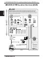
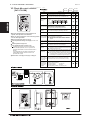
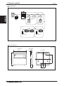
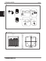
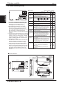
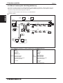
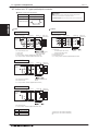
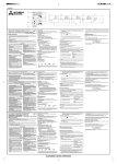
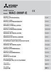
MELANS has a large line-up, including local remote controllers, timers, group controllers, central controllers,
integrated system software, PLC and its software, as well as BMS interface hardware and software. The
combination of the MELANS products can fulfill the requirements of small-scaled control system, middlescaled control system up to 2,000 indoor units, and/or large-scaled open systems affiliated with a BMS system.
Moreover, with central controller G-50A/GB-50A, PC browser and remote access (monitoring and operating) via
communication network is possible and easy.
All of the local remote controllers
feature liquid crystal LED displays
and are easy to operate.
ON/OFF
Controller
PAC-YT51CRB
®
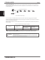
PEFY-P-NMLU-E
PEFY-P-NMHU-E
PDFY-P-NMU-E
PMFY-P-NBMU-E
PLFY-P-NCMU-E
PLFY-P-NBMU-E
PCFY-P-NGMU-E
PKFY-P-NAMU-E
PKFY-P-NGMU-E
PKFY-P-NFMU-E
PFFY-P-NEMU-E
PFFY-P-NRMU-E
(SW-BACnet)
This is a middle-scaled air
conditioning management
system, in which up to 2,000
indoor units can be centrally
controlled
MITSUBISHI ELECTRIC’s CITY MULTI® can be
easily connected to the building management
system through BACnet®.
CONTROLLER CONTROLLER
CNTR-
Cntr- 2
1. MITSUBISHI ELECTRIC's Air-conditioner Network System. (MELANS)
DATA U3
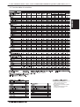
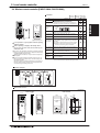
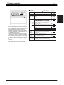
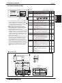
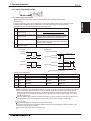
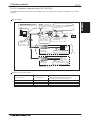
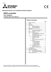
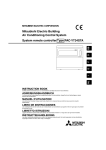
1-1. Function table of controllers
CONTROLLER
Timer Operation
®
LMAP03U: LonWorks® Interface
Controls up to 50 Groups/ 50 Indoor,
Details refer to its description.
PAC-YG31CDA: BACnet® Interface Software
(SW-BACnet)
Controls up to 500 Groups/ 500 Indoor,
For details, see its description.
CONTROLLER
CNTR-
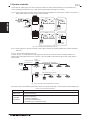
2. Local remote controller
DATA U3
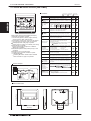
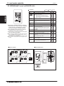
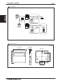
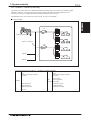
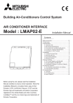
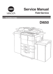
2-1. Deluxe MA remote controller [PAR-21MAA]
Functions
AFTER
ERROR CODE
WEEKLY
SIMPLE
AUTO OFF
ONLY1Hr.
CONTROLLER
TEMP.
MENU
PAR-21MAA
MONITOR/SET
ON/OFF
FILTER
CLOCK
Switches between Cool / Dry / Auto / Fan / Heat.
Operation modes vary depending on the air conditioner unit.
Auto mode is only for the CITY MULTI® R2- and WR2-Series.
Temperature
setting
Sets the temperature for a single group
Range of temperature setting
Cool/Dry :
:
Heat
Auto
:
Fan speed
setting
Models with 4 air flow speed settings: Hi/Mid-2/Mid-1/Low
Models with 3 air flow speed settings: Hi/Mid/Low
Models with 2 air flow speed settings: Hi/Low
Air flow
direction
setting
Air flow direction angles 100% - 80% - 60% - 40%, Swing,
Louver ON/OFF
Air flow direction settings vary depending on the model.
CHECK TEST
OPERATION
( ) For PDFY/PEFY/PFFY by setting Dip SW 7-1 to ON and limits to HIGH fan speed only.
CLEAR
High-quality white color body and light-green display.
Dot liquid-crystal display is applied.
Choose from Japanese, Chinese, English, Germany,
Spanish, Russian, Italian, French displays.
Connectable to all CITY MULTI® indoor unit, and automatically adjust its function with the indoor unit connected.
Limiting temperature setting range is possible.
Help to avoid over-cooling or over-heating. Save energy.
Auto-stop timer is available.
Help to avoid forgetting to stop the air conditioner.
Weekly timer is available.
ON/OFF/Temperature setting 8 times per day, 1 week
scheduling.
Grouping via cross-over wire directly.
Usable as the local remote controller for system
controller (MELANS)
Combining ME remote controller and/or LOSSNAY
remote controller in a group is not possible.
Weekly
Timer
ON/OFF/Temperature setting can be done up to 8 times one
day in the week.
The time can be set by the minute.
Permit / Prohibit
local operation
Individually prohibit operation of each local remote control
function (Start/Stop, Change operation mode, Set
temperature, Reset filter).
1: When the local remote controller inactivation command
is received from the master system controller,
" " is displayed.
Prohibition/permission
of specified mode
(Cooling prohibited
/heating prohibited
/cooling-heating prohibited)
By the setting from System Controller, the operation for the
following modes is prohibited.
At cooling prohibited
: Cool, Dry, Auto,
At heating prohibited
: Heat, Auto,
At cooling-heating prohibited : Cool, Heat, Dry, Auto
Indoor unit intake
temperature
Measures the intake temperature of the indoor unit when
the indoor unit is operating.
Error
When an error is currently occurring on an air conditioner
unit, the afflicted unit and the error code are displayed.
Test run
This operates air conditioner units in test run mode.
Ventilation
equipment
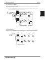
System example
Non-polarized
2-wire
Non-polarized
2-wire
MA
remote
controller
Operations Display
Operation mode
switching
ON/OFF
DAY
:Not available
Run and stop operation for a single group
TEMP.
BACK
:Each block
:Collective
ON/OFF
AFTER OFF
FUNCTION
FILTER
:Each group
:Each floor
Description
Item
TIME SUN MON TUE WED THU FRI SAT
TIMER
Hr
ON
:Each unit
1
Up to 16 indoor units can be connected to an interlocked
system that has one LOSSNAY. LOSSNAY items that can
be set are "Hi" "Low" "Stop". Ventilation mode switching is
not available.
Function to limit
the setting range
of room
temperature
(Set temperature
range limit)
The range of room temperature setting can be limited by the
initial setting.The lowest limit temperature can be made higher
ying, while the upper
limit temperature lo
Easy-to-operate
simplified locking
function
(Auto lock function)
Setting/releasing of simplified locking for remote control
switch can be performed.
· Locking of all switches
· Locking of all switches except Start/Stop switch
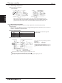
MA
remote
controller
External dimension
(Side view)
(Rear view)
19
[ 3/4 ]
46 [1-13/16]
Unit:mm[in.]
120 [4- 23 /32 ]
83.5 [3- 9 /32 ]
(Front view)
130 [5-1/8 ]
CONTROLLER
CNTR-
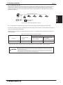
2. Local remote controller
DATA U3
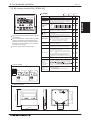
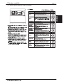
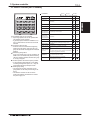
2-2. ME remote controller [PAR-F27MEA-US]
Functions
PAR-F27MEA-US
FAN SPEED
AIR DIRECTION
LOUVER
VENTILATION
Operation mode
switching
Switches between Cool / Dry / Auto / Fan / Heat.
Operation modes vary depending on the air conditioner unit.
Auto mode is only for the CITY MULTI® R2- and WR2-Series.
FILTER
Temperature
setting
Three timer modes are available with its enhanced
timer function.
The room temperature can be limited by the initial
setting. By setting the room temperature range
narrower than usual setting, cooling/heating operation with excessive temperature can be prevented and thus save energy.
Allows for simple “button locking” function.
Sets the temperature for a single group
Range of temperature setting
Cool/Dry :
:
Heat
Auto
:
( ) For PDFY/PEFY/PFFY by setting Dip SW 7-1 to ON and limits to HIGH fan speed only.
CHECK TEST
TIMER SET
Operations Display
Run and stop operation for a single group
ON/OFF
CLOCK ON OFF
:Not available
CONTROLLER
TIMER
:Each block
:Collective
ON/OFF
SET TEMP.
MODE
:Each group
:Each floor
Description
Item
SET TEMP.
:Each unit
Fan speed
setting
Models with 4 air flow speed settings: Hi/Mid-2/Mid-1/Low
Models with 3 air flow speed settings: Hi/Mid/Low
Models with 2 air flow speed settings: Hi/Low
Air flow
direction
setting
Air flow direction angles 100% - 80% - 60% - 40%, Swing,
Louver ON/OFF
Air flow direction settings vary depending on the model.
Permit / Prohibit
local operation
Individually prohibit operation of each local remote control
function (Start/Stop, Change operation mode, Set
temperature, Reset filter).
1: When the local remote controller inactivation command
is received from the master system controller, "CENTRALLY CONTROLLED -" is displayed.
Indoor unit intake
temperature
Measures the intake temperature of the indoor unit when
the indoor unit is operating.
Error
When an error is currently occurring on an air conditioner
unit, the afflicted unit and the error code are displayed.
Timer operation
1
Thanks to the three timer modes equipped, a proper mode
can be selected to meet the usage.
One day timer : ON/OFF setting of one time on one day can be applied.
Daily timer
: ON/OFF setting by the One day timer can be repeated for
everyday.
Auto OFF timer : OFF timer can be set in a range from 30 minutes to 4 hours.
Setting of Auto OFF timer automatically activates OFF timer at the next operation.
This function can be utilized to prevent the negligence of OFF setting.
Weekly schedule in only one patterns can be employed by connecting Program timer. 2
System example
ME
remote
controller
Test run
This operates air conditioner units in test run mode.
Function to limit
the setting range
of room
temperature
(Set temperature
range limit)
The range of room temperature setting can be limited by the
initial setting.The lowest limit temperature can be made higher
ying, while the upper
limit temperature lo
Easy-to-operate
simplified locking
function
(Auto lock function)
Setting/releasing of simplified locking for remote control
switch can be performed.
· Locking of all switches
· Locking of all switches except Start/Stop switch
When making the function to limit room temperature setting range
effective, the operation mode cannot be set to the auto mode.
ME
remote
controller
External dimension
(Side view)
(Rear view)
130 [5-1/8 ]
19
[ 3/4 ]
46 [1-13/16]
Unit:mm[in.]
120 [4- 23 /32 ]
83.5 [3- 9 /32 ]
(Front view)
CONTROLLER CONTROLLER
CNTR-
Cntr- 5
2. Local remote controller
DATA U3
2-2.
remote
[PAR-F27MEA-US]
2-3. ME
Simple
MA controller
remote controller
[PAC-YT51CRB]
Functions
CONTROLLER
Operation mode
switching
Item
SET TEMP.
MODE
TIMER
PAR-F27MEA-US
ON/OFF
CLOCK ON OFF
FAN SPEED
AIR DIRECTION
LOUVER
VENTILATION
FILTER
CHECK TEST
TIMER SET
Control: START/STOP, room temperature, fan
speed, and operation mode selection
Three
timer
modes
are available
with its
enhanced
The
only
wiring
required
is cross-over
wiring
based
timer
function.
on
two-wire
signal lines.
The room
temperature
canisbe
limited
Room
temperature
sensor
built
in by the initial
setting.
By settingsetting
the room
range
LCD
temperature
andtemperature
display in 1°C
/1°F
narrower than usual setting, cooling/heating operunit.
ation
with excessive
temperature
can be preventSet
temperature
range
limit
ed and
thus save
energy.
Can
operate
all types
of indoor units
Allows
for simple
“button
locking”
function.
If additional
features are
needed
beyond Simple
MA
PAC-YT51CRB capabilities, use it in conjunction with
Deluxe MA PAR-21MAA or Central Controllers G-50A or
GB-50A.
Using Simple MA PAC-YT51CRB in combination with
PAR-F27MEA-US M-NET Remote Controller is not
permitted inside a group.
Dimensions: 2-3/4 (W) x 4-3/4 (H) x 1-5/8 (D) in.
System example
ME
remote
controller
:Each group
:Each block
:Each floor
:Collective
:Not available
Operations Display
Description
Item
ON/OFF
:Each unit
Run and stop operation for a single group
:Each unit
:Each group
:Each block
Switches between Cool / Dry / Auto / Fan / Heat.
:Each floor unit.
:Collective
:Not available
Operation modes vary depending on the air conditioner
® R2- and WR2-Series only.
Auto mode is the CITY MULTIDescription
Operations Display
Sets Run
the temperature
for a single
ON/OFF
and stop operation
for agroup
single group
Range of temperature setting
Switches
between Cool / Dry / Auto / Fan / Heat.
Temperature
Cool/Dry
:
modes vary depending on the air conditioner unit.
:
Operation modeHeat Operation
setting
®
Auto Auto: mode is only for the CITY MULTI R2- and WR2-Series.
switching
( ) ForSets
PDFY/PEFY/PFFY
by setting
SW 7-1
to ON and limits to
the temperature
for aDip
single
group
HIGH Range
fan speed
ofonly.
temperature setting
SET TEMP. Temperature
ModelsCool/Dry
with 4 air: flow speed settings: Hi/Mid-2/Mid-1/Low
setting
Heat
Models with 3 air: flow speed settings: Hi/Mid/Low
Fan speed setting
ModelsAuto
with 2 air: flow speed settings: Hi/Low
( ) For PDFY/PEFY/PFFY by setting Dip SW 7-1 to ON and limits to HIGH fan speed only.
Fan speed setting varies depending on the model.
Models with 4 air flow speed settings: Hi/Mid-2/Mid-1/Low
speed Air flow direction angles (4-angle, Swing) Louver ON/OFF
Air flow Fan
direction
Models with 3 air flow speed settings: Hi/Mid/Low
Air flow
direction
depending
the model.
setting setting
Models
with settings
2 air flowvary
speed
settings:on
Hi/Low
Air flow
Timer operation
direction
setting
Air flow direction angles 100% - 80% - 60% - 40%, Swing,
Not available
Louver ON/OFF
Air flow direction settings vary depending on the model.
Individually prohibit operation of each local remote control
Individually
prohibit
of each local remote control
function
(Start/Stop,
Set operation
temperature).
Permit / Prohibit
function
Change
operation
mode,command
Set
1: When
the(Start/Stop,
local remote
controller
inactivation
is
local operation
temperature,
filter).system controller, "CENTRAL" is
received
from Reset
the master
Permit / Prohibit
1: When the local remote controller inactivation command
displayed.
local operation
is received from the master system controller, "CONTROLLED
is displayed.
Indoor unit intake Measures CENTRALLY
the intake temperature
of the -"
indoor
unit only when
temperature
the indoor unit is operating.
Indoor unit intake
Measures the intake temperature of the indoor unit when
Whenthe
anindoor
error isunit
currently
occurring on an air conditioner unit,
temperature
is operating.
Error
the afflicted unit and the error code are displayed.
When an error is currently occurring on an air conditioner
Error
unit, the afflicted
unit andunits
the error
are displayed.
This operates
air conditioner
in testcode
run mode.
Test run
2: The display for test run mode will be the same as for normal
Thanks
to
the
three
timer
modes
equipped,
a proper mode
start/stop (no display "test run").
can be selected to meet the usage.
Up to 16 indoor units can be connected to an interlocked system
Ventilation
Oneone
day timer
: ON/OFF setting of one time on one day can be applied.
that has
LOSSNAY.
equipment
Daily
timer
: ON/OFF
setting will
by the
day timerwhen
can bethe
repeated
for
3: The
interlocked
LOSSNAY
beOne
enabled
indoor
Timer operation
everyday.
unit(s) are enabled.
LOSSNAY ON/OFF status is displayed
Auto
OFF
timer
:
OFF
timer
can
be
set
in
a
range
from
30
minutes
to
4
hours.
on the Simple MA PAC-YT51CRB. Fan speed and ventilation
1
1
2
3
3
Setting of Auto OFF timer automatically activates OFF timer at the next operation.
mode
not
available
through
thesetting.
Simple MA.
This switching
function can beare
utilized
to prevent
the negligence
of OFF
Weekly
scheduletemperature
in only one patterns
can be employed
connecting
The range
of room
setting
can bebylimited
byProgram
the timer. 2
Function to limit
initial setting.The lowest limit temperature can be made higher
the setting range
temp.
of room
Test run
This
operates
air
conditioner
units
in
test
run
mode.
than the usual (67°F/19°C) at cooling/drying, while the upper
(Set temperature limit temperature lower than the usual (83°F/28°C) at heating.
Function
range
limit) to limit
The range of room temperature setting can be limited by the
the setting range
initial setting.The lowest limit temperature can be made higher
Prohibition/permission
By the setting from System Controller, the operation
forthe
theupper
of room
ying, while
of specified
mode
following
is prohibited.
temperature
limit modes
temperature
lo
/heating
(Setprohibited
temperature At cooling
When
making the function
to limitDry,
room
temperature setting range
prohibited
: Cool,
Auto,
/cooling-heating
effective,
the operation mode
cannot
be set to the auto mode.
range limit)
At heating
prohibited
: Heat,
Auto,
prohibited)
At cooling-heating prohibited : Cool, Heat, Dry, Auto
Setting/releasing of simplified locking for remote control
Easy-to-operate
switch can be performed.
simplified locking
· Locking of all switches
function
· Locking of all switches except Start/Stop switch
(Auto lock function)
ME
remote
controller
External dimension
(Side view)
(Rear view)
130 [5-1/8 ]
19
[ 3/4 ]
46 [1-13/16]
Unit:mm[in.]
120 [4- 23 /32 ]
83.5 [3- 9 /32 ]
(Front view)
CONTROLLER CONTROLLER
CNTR-
Cntr- 5
2. Local remote controller
DATA U3
2-4. Wireless remote controller [PAR-FL32MA / PAR-FA32MA]
Functions
PAR-FL32MA
It can operate in a group system without requiring
address settings.
When operating, it displays LED lamps. When
errors occur, the error code can be shown by the
LED flash count.
If an indoor unit with different functionality is operating inside the
same group, please note there may be cases when functionality
is partially disabled for batch control.
Wireless remote controllers can only be used for a single refrigerant system.
If you use a system controller to centrally control a group, you
will need cross-wiring between indoor units when using a wireless remote controller.
Also ensure there is no difference between the group setting of
the main system controller and the cross wiring across indoor
units when wiring and setting cross wires.
:Not available
Operations Display
ON/OFF
Run and stop operation for a single group
Operation mode
switching
Switches
Cool // Dry
Dry // Fan
Fan // Heat
Heat // Auto
Auto..
Switches between
between Cool
Operation
vary depending
depending on
on the
the air
air conditioner
conditioner unit.
unit.
Operation modes
modes vary
®
Auto
Multi
R2 and
WR2
series
R2andonly.
WR2-Series.
Auto mode
mode is
is the
onlyCity
for the
CITY
MULTI
Temperature
setting
Sets the temperature for a single group
Range of temperature setting
Cool/Dry :
Heat :
Auto :
Fan speed setting
Models with 4 air flow speed settings: Hi/Mid-2/Mid-1/Low
Models with 2 air flow speed settings: Hi/Low
Air flow direction
setting
Air flow direction angles 100% - 80% - 60% - 40%, Swing.
Air flow direction settings vary depending on the model.
Timer operation
One ON/OFF setting can be set for one day.
COOL
PAR-FA32MA
(Signal receiving unit)
:Each block
:Collective
Permit / Prohibit
local operation
CONTROLLER
HEAT
:Each group
:Each floor
Description
Item
ON/OFF
:Each unit
Individually prohibit operation of each local remote control
function (Start/Stop, Change operation mode, Set temperature,
Reset filter).
� If operation is performed when the local remote controller
inactivation command is received from the main system
controller, a buzzer will ring and an LED will flash.
1
Indoor unit intake
temperature
Measures the intake temperature of the indoor unit when the
indoor unit is operating.
Error
When an error occurs on the air conditioner unit, the operation
lamp on the signal receiving unit will flash.
Test run
This operates air conditioner units in test run mode.
Ventilation
equipment
Up to 16 indoor units can be connected to an interlocked system
that has one LOSSNAY.
Some models will have different display for the air flowdirection and fan speed.
Set the air flow direction and fan speed when performing initial setting.
System example
Non-polarized
2-wire
Signal
receiving
unit
Signal
receiving
unit
Wireless
remote
controller
Wireless
remote
controller
Nonpolarized
2-wire
Signal
receiving
unit
Nonpolarized
2-wire
Wireless
remote
controller
External dimension
PAR-FL32MA
58[2-9/32]
19[3/4]
22.5[7/8]
70[2-3/4]
CHECK TEST RUN
MODEL SELECT
Unit:mm[in.]
PAR-FA32MA
9.9[3/8]
4.8[3/16]
�C
AMPM
COOL
4.6
[3/16]
HEAT
120[4-23/32]
ON/OFF
159[6-1/4]
TEMP
35.2[1-3/8]
83.5[3-9/32]
19[3/4]
AMPM
NOT AVAILABLE
ON/OFF
CONTROLLER CONTROLLER
9.2[3/8]
CNTR-
Cntr- 7
2. Local remote controller
DATA U3
2-5.
remoteremote
controller
[PZ-52SF]
2-5. LOSSNAY
LOSSNAY M-NET
controller
[PZ-52SF]
Functions
ON/OFF
HEAT EX.
BY-PASS
AUTO
CONTROLLER
CHECK
NOT AVAILABLE FILTER
Operation mode
switching
ON/OFF
FILTER
Stand-alone LOSSNAY
LOSSNAY operation
operation is
is possible
possible by
by
Stand-alone
commands
commands from
from aa central
central controller
controller or
or LOSSNAY
LOSSNAY
remote
is acontroller
central
remote controller.
controller. (G-50A/GB-50A
(G-50A is a central
controller
that LOSSNAY
supports LOSSNAY
that supports
operation.)operation.)
The LOSSNAY remote controller is capable of
changing the air flow and vent modes.
All the wiring is cross-wiring that uses non-polar
two wire system signal cables.
: When setting up a LOSSNAY stand-alone system or when setting up a LOSSNAY and central controller system, connect a
power supply unit for the signal cables.
: It is impossible to use a LOSSNAY remote controller for LOSSNAY unit that is interlocked other indoor unit (except for some
models).
:Each group
:Each block
:Each floor
:Collective
:Not available
Operations Display
Description
Item
CENTRAL INTERLOCKED
:Each unit
Run and stop operation for a LOSSNAY unit
Switches between automatic ventilation/ vent - heat
interchange/ normal ventilation
Note: Operation modes vary depending on the model.
When connecting to only models without a damper,
these models cannot be used.("NOT AVAILABLE" will
appear in the display.)
Temperature
setting
Not available
Fan speed setting
Models with 2 air flow speed settings: Hi/Low
When only connected to single notch models, this function is
disabled.
Air flow direction
setting
Not available
Timer operation
Not available
Permit / Prohibit
local operation
Individually prohibit operation of each local remote control
function (Start/Stop, Reset filter).
1: When the local remote controller inactivation command is
received from a master system controller, " CENTRAL " is
displayed.
Indoor unit intake
temperature
Not available
Error
When an error occurs on the air conditioner unit, the operation
lamp on the signal receiving unit will flash.
Test run
1
There is no test run switch for LOSSNAY remote controllers.
Set test run on a LOSSNAY by using the test run switch on the
LOSSNAY unit.
2: Cancel by operating the start/stop switch after switching off
the LOSSNAY unit test run switch.
2
Ventilation
equipment
Up to 16 indoor units can be connected to an interlocked system
that has one LOSSNAY.
Interlocked
operation
This is displayed to indicate it is being operated by an operation
control unit's external control terminal for an interlocked system
that contains LOSSNAY units and indoor units.
External dimension
System example
Unit:mm[in.]
ABS
LOSSNAY
unit
LOSSNAY remote
controller
REMOTE CONTROLLER
MODEL
ON/OFF
UP
LOSSNAY
unit
LOSSNAY remote
controller
LOSSNAY
unit
LOSSNAY
unit
LOSSNAY remote
controller
LOSSNAY
unit
78[3-1/16]
LOSSNAY remote
controller
LOSSNAY
unit
PZ-52S F-E
INPUT VOLTAGE
WEIGHT
SERIAL No.
MADE IN JAPAN
DC30V
0.02A
0.15kg
KT79C117H01
83.5[3-9/32 ]
LOSSNAY
unit
120[ 4-23/32]
LOSSNAY
unit
FILTER
Power supply unit
70[ 2-3/4 ]
8
[5/16] 33[1-5/16 ]
(41[1- 5/8])
48[1-7/8 ]
CONTROLLER CONTROLLER
CNTR-
Cntr- 8
3. System controller
3-1. System group controller [PAC-SF44SRA]
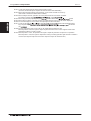
Auto only supported for the CITY MULTI® R2- and WR2-Series.
CONTROLLER
( ) For PDFY/PEFY/PFFY by setting Dip SW 7-1 to ON and limits to HIGH fan speed only.
CONTROLLER
CNTR-
3.
controller
3. System
System remote
controller
DATA U3
System
remote
controller
UP
Power
supply
unit
MA remote
controller
LOSSNAY
MA remote
controller
LOSSNAY
LOSSNAY
remote controller
LOSSNAY
LOSSNAY
remote controller
External dimension
Unit:mm[in.]
130[5-1/8 ]
(Side view)
18.5
2[3/32 ] [23/32 ]
(Rear view)
83.5[ 3-9/32 ]
(Front view)
120[ 4-23/32 ]
CONTROLLER
System example
19
[ 3/4 ]
46[1-13/16]
CONTROLLER
CONTROLLER
CNTR-10
Cntr- 11
3.
3. System
System controller
remote controller
DATA U3
3-2. Schedule timer [PAC-YT34STA]
Functions
MONITOR
PATTERN Sun Mon Tue Wed Thu Fri Sat
WEEKLY SET
COLLECTIVE
GROUP
OPERATION
ON
ON
CHECK
OFF
TIMER OFF
SET TEMP.
PROH.
: Each group
: Each floor
: Group or collective
Details
Item
ON/OFF
: Each unit
Unit control
50 units/50 groups (Maximum 16 units connected in one group)
Schedule control
One week
: Each block
: Not available
Operations Display
PERMIT
ON/OFF
MODE
TEMP.
ON/OFF
Timer reset
Setting
details
Schedule
function
Number of
settings
The weekly schedule of up to 50 groups/50 units
can be controlled with one schedule timer.
The weekly schedule of up to ten patterns (no setting + nine patterns) is available for setting.
"ON/OFF", "Operation Prohibit", "COOL /HEAT"
and "Set Temperature" can be scheduled with up
to 16 settings in one pattern.
It can be connected to the central control transmission line or to the indoor/outdoor transmission
line without the power supply unit. It is non-polar
2-wire.
It can be interlocked with a building management
system using the external input/output managing
function.
An error unit address and error code appear on
the display in case of malfunction happening.
Time setting unit
ON/OFF operations can be carried out collectively or for each
group.
CONTROLLER
Operation
The timer setting details can be disabled collectively
ON/OFF
COOL/HEAT
Operation prohibit (ON/OFF, operation mode, setting temperature)
Number of setting patterns: Ten (no setting + nine patterns)
(Operation for a week can be set by selecting one of ten
patterns for each day.)
Number of operations: Up to 16 operations can be set in one pattern
The item can be set in five-minute units
Current time and day
Display
Error state
Unit operation state
External input
(Timer connection,
emergency stop
input, etc.)
The following can be input with the level signals or pulse signals.
Level signal: "Emergency stop input" or "Collective ON/OFF"
Pulse signal: "Collective ON/OFF" or "Local remote controller
prohibit/permit"
One input can be selected from those above.
External output
(Error output,
operation output)
"ON/OFF" and "error/normal" are output with the level signal.
The optional output cable is required.
Connection position
Indoor/outdoor transmission line: Connectable
Central system transmission line: Connectable (Optional power
supply unit (PAC-SC50KUA) is needed.)
CONTROLLER
CONTROLLER
CNTR-11
Cntr- 12
3.
3. System
System controller
remote controller
DATA U3
CONTROLLER
System example
System
System
group
remote
controller
controller
UP
Power supply
unit for
transmission
line
LOSSNAY
PAR-F27MEA-US
Schedule timer
PAR-21MAA
PAC-YT51CRB
PAC-YT51CRA
External dimension
Unit:mm[in.]
18.5
2[3/32 ] [23/32 ]
(Rear view)
120[ 4-23/32 ]
130[5-1/8 ]
(Side view)
83.5[ 3-9/32 ]
(Front view)
19
[ 3/4 ]
CONTROLLER
46[1-13/16]
CONTROLLER
CNTR-12
Cntr- 13
3. System
System controller
remote controller
3.
DATA U3
3-3. ON/OFF
ON/OFF controller
remote controller
[PAC-YT40ANRA]
3-3.
[PAC-YT40ANRA]
Functions
CENTRALIZED
ON/OFF
Operation mode
switching
.
.
.
.
●.
: Each block
: Group or collective
: Not available
Operations Display
Run and stop operation for the air conditioner units
Not available
Temperature setting
Not available
Fan speed setting
Not available
Air flow direction setting
Not available
Manual operation
prohibit/permit
(ON/OFF, operation mode,
setting temperature, filter reset)
Compatible only with external input.
Specific mode
operation prohibit
(Cooling prohibit, heating
prohibit, cooling/heating prohibit)
Not available
Room temperature display
Not available
Error display
LED flashes during failure.
(The error code can be confirmed by removing the cover.)
Schedule operation
Not available
Ventilation operation
(independent)
Group operation of only LOSSNAY units possible.
Only ON/OFF of group.
Ventilation operation
(interlocked)
The LOSSNAY will run in interlock with the operation of indoor
unit.
The fan rate and mode cannot be changed. The LED will turn
ON only during operation after interlocking.
External output
(Error output,
operation output)
"ON/OFF" and "error/normal" are output with the level signal.
The optional output cable is required.
Connection position
Indoor/outdoor transmission line: Connectable
Central system transmission line: Connectable (Power supply
unit (PAC-SC50KUA) is needed.)
CONTROLLER
16 groups/50 units can be controlled.
Up to 16 groups/50 units can be operated with
one ON/OFF remote controller.
A general-purpose interface is available for control, so general devices can also be turned ON
and OFF.
Just press a switch to start.
All of the units can be started and stopped by
pressing the main switch, and each unit in the
group can be started and stopped with individual
switches.
LED flashing during failure.
If any error should occur in the air conditioner, its
details can be confirmed easily with the flashing
LED. The LED also indicates whether each group
is running or stopped.
operation with
with external
external system
system possible.
possible.
IInterlock
nterlock operation
It
can
be
flexibly
interlocked
with
a
card
▪ It can be flexibly interlocked with a card reader,
reader,
fire
alarm system
or building
management
or building
management
system,
etc., usingsysthe
tem,
etc., using
the incorporated
incorporated
external
input/outputexternal
function.
input/output
Flexible
groupfunction.
setting.
Flexible
groupcan
setting.
▪ The groups
be easily configured, so the
The
groups
can
bebe
easily
so the
group pattern can
freelyconfigured,
set according
to the
group pattern can be freely set according to the
layout.
layout.
▪ The ON/OFF controller can be connected
The ON/OFF remote controller can be connected
at the indoor/outdoor transmission line without
at the indoor/outdoor transmission line without
the power supply unit.
the power supply unit.
: Each group
: Each floor
Description
Item
ON/OFF
: Each unit
●
.
.
CONTROLLER CONTROLLER
Cntr- 14
CNTR-13
3.
3. System
System controller
remote controller
DATA U3
ON/OFF
remote
controller
UP
LOSSNAY
Power
supply
unit
PZ-52SF
PAR-F27MEA-US
PAC-YT51CRB
PAR-21MAA
External dimension
(Front view)
18.1
[ 23/32 ]
130[ 5-1/8 ]
(Rear view)
ON/OFF
83.5 [3-9/32 ]
CENTRALIZED
Unit:mm[in.]
(Side view)
120[4-23/32]
CONTROLLER
System example
19
[ 3/4 ]
CONTROLLER CONTROLLER
46[1-13/16 ]
CNTR-14
Cntr- 15
3.
3. System
System controller
remote controller
DATA U3
3-4. Central controller [G-50A]
Functions
ON/OFF
TEST RUN
ON/OFF
73 ºF
2
4
5
TEMP.
7
3
CLOCK/
PATTERN
VENTILATION
TIMER
MODE
RESET
0
BACK
SCREEN
6
9
ENTER
:Each block
:Collective
:Not available
Operations
Run and stop operation for the air conditioner units
Operation mode
switching
Switches between Cool / Dry / Auto / Fan / Heat.
(Group of LOSSNAY unit : automatic ventilation/ vent - heat
interchange/ normal ventilation)
Operation modes vary depending on the air conditioner unit.
®
Auto
Multi
R2 and
WR2
series
only. series.
Auto mode
mode is
is the
onlyCity
for the
CITY
MULTI
R2
and WR2
Display
CONTROLLER
ON/OFF
INS.
DEL.
:Each group
:Each floor
Description
Item
GROUP
SELECT
AIR
DIRECTION
8
REMOTE
PROHIBITION
CENTRAL CONTROLLER
G-50A
FAN SPEED
MODE
1
:Each unit
Range of temperature setting
Cool/Dry :
:
Heat
Auto
:
Temperature
setting
in case
case of
of PDFY/PEFY/PFFY-E
using middle-temperature
indoor
(( )) in
indoor
unit. unit.
Range of temperature settings vary depending on model.
A. The central controller of G-50A combines Web
function (optional), which enable the air conditioner
system management on a PC browser screen.
The management even carried out at a long distance place via public telephone line.
Microsoft® Internet explorer Ver. 5 or later by
Microsoft Corporation is needed. Microsoft is a
registered trade mark of Microsoft Corporation in
the United States and other countries.
B. Together with integrated centralized control software
TG-2000A, and/or PLC, many optional functions like
"Charging", "Peak-cut", "Energy saving", "General
equipment management", "Scheduling" etc, can be
carried out. Details, please refer to sections of TG2000A and PLC software.
C. One G-50A can control maximum 50 Indoor units
(including Lossnay). The TG-2000A can manage
maximum 40 G-50As, therefore can manage
maximum 2000 Indoor units (including Lossnay).
D. Taking advantage of G-50A's Web functions, alarming E-mail containing address and error code can
be sent to appointed E-mail address upon any fault
happen at the air conditioner system. This could
release standby personnel and save operation
cost.
Fan speed setting
Models with 4 air flow speed settings: Hi/Mid-2/Mid-1/Low
Models with 3 air flow speed settings: Hi/Mid/Low
Models with 2 air flow speed settings: Hi/Low
Air flow direction
setting
Air flow direction angles 100% - 80% - 60% - 40%, Swing,
1: Louver cannot be set.
Air flow direction settings vary depending on the model.
Timer operation
For one day, you can set start/stop three times and you can set
enable/disable three times.
For a week's schedule, you can store three start/stop patterns
and one enable/disable pattern.
2: When the timer is set, "Timer enabled" is shown on the
operation setting screen of the LCD.
Permit / Prohibit
local operation
Indoor unit intake
temperature
2
Individually prohibit operation of each local remote control
function (Start/Stop, Change operation mode, Set temperature,
Reset filter).
3: When the local remote controller inactivation command is
received from the master system controller, disabled mark
appears in inverted display on the operation screen.
3
Measures the intake temperature of the indoor unit only when
the indoor unit is operating.
When an error is currently occurring on an air conditioner unit,
the afflicted unit and the error code are displayed.
4: When an error occurs, the LED flashes. The operation
monitor screen shows the abnormal unit by flashing it. The
error monitor screen shows the abnormal unit address,
error code and source of detection. The error log monitor
screen shows the time and date, the abnormal unit
address, error code and source of detection.
Error
4
This operates air conditioner units in test run mode.
Test run
The interlocked system settings can be performed by the master
system controller.
When setting the interlocked system, you can use the ventilation
switch to switch the free plan LOSSNAY settings between "Hi",
"Low" and "Stop".
When setting a group of only free plan LOSSNAY units, you can
switch between "Normal ventilation", "Interchange ventilation"
and "Automatic ventilation".
Ventilation
equipment
By using accessory cables you can set and monitor the
following.
Input
By level signal: "Batch start/stop", "Batch emergency stop"
By pulse signal: "Batch start/stop", "Enable/disable local
remote controller"
Output
"Start/stop", "Error/Normal"
5: Requires the external I/O cable (PAC-YG10HA-E) sold
separately.
External
input/output
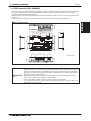
External dimension
5
5
Unit:mm[in.]
25
[31/32]
300[11-13/16 ]
70[2-3/4 ]
ON/OFF
120[ 4-3/4]
1
CENTRAL CONTROLLER
G-50A
3[1/8]
57[2-1/4 ]
19[3/4]
34
[1-5/16]
288[11-11/32]
138[5-7/16]
47[1-27/32 ]
83.6[3- 9 / 32]
13 [1/2]
83.5[3-9/32]
B
S
12VDC GND
RS232C
1 CN1 5
1
CN2
POWER
9
28
[1-1/8]
A
M-NET
91[ 3-19/32]
Installation plate
106[4-3/16 ]
220 [8-21/32]
280[11 ]
Ethernet
21
[13/16]
46
[1-13/16 ]
47[1-27/32 ]
CONTROLLER CONTROLLER
CNTR-15
Cntr- 16
3. System remote controller
DATA U3
Powercontroller
supply to G-50A
3.3-4-1.
System
G-50A needs DC power supply of 24~30V and 12V; the former is for central control transmission use and the latter is for
G-50A's operating and LAN function use. G-50A can have power-supply at following 1,2,3 methods.
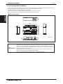
3-4-1-1. Power supply unit PAC-SC50KUA is the recommended power supplier for G-50A. The basic scheme is as follows. For
details, please refer to 3-6 Power supply unit PAC-SC50KUA.
CONTROLLER
LAN
M-NET
M-MET
12V DC
Central controller
G-50A
UP
POWER SUPPLY UNIT
PAC-SC50KUA
MODE
L
POWER TING
RA
2.11kg
WEIGHT
SERIA
L No.
MITSUBIS
HI ELECT
RIC CORP
ORATION
Power supply unit
PAC-SC50KUA
ME remote
controller
ME remote
controller
M-NET
LOSSNAY unit
LOSSNAY M-NET
remote controller
ME remote
controller
Fig. 3-4-1 G-50A and PAC-SC50KUA basic scheme.
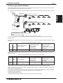
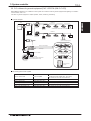
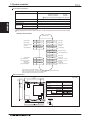
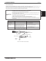
3-4-1-2. Power supply of DC 30V from connector of TB7 or TB3 of Outdoor unit and field supplied DC12V, which specified at
Table 3-4-1.
3-4-1-2-1. TB7 and field supplied DC 12V, 0.2A.
As shown at Fig. 3-4-2, G-50A receives power supply of DC 30V from the connector of TB7 at the R410A Outdoor unit
together with a field supplied DC12V, 0.2A. In the case, one of the Outdoor units should change its power supply switch of
CN41 to CN40.
Centralized control
transmission line
R410A
Outdoor unit
Indoor/outdoor transmission line
CN41
CN40
Field supplied power
(DC12V 0.2A)
Indoor/outdoor transmission line
CN41
Fig. 3-4-2 G-50A, TB7 and field supplied DC12V scheme.
DC12V Power source should follow the specifications at Table 3-4-1, and the power cable to G-50A should not exceed 10m 32-3/4ft .
Table 3-4-1 DC12V power specifications
Source power
DC12V 0.2A (Maximum loading)
Ripple noise
Lower than 150mVp-p
Compatible
specification
Authorized or CE marked products.
Subject to regulations:
IEC60950 (or EN60950)
CISPR22/24 (or EN55022/24)
IEC61000-3-2/3-3 (or EN61000-3-2/3/3)
CONTROLLER
Cntr- 17
CONTROLLER
CNTR-16
3. System remote controller
3. System controller
DATA U3
3-4-1-2-2. TB3 and DC 12V, 0.2A
G-50A can also receive power supply from TB3 connector of the R410A or R407C, R22 Outdoor unit. Yet, Outdoor unit down
will lead down to G-50A too. The kind of connection is possible but not recommended air conditioner system of multiple
Outdoor units. The DC 12V 0.2A can be supplied at TB3 connector of PAC-SC50KUA, or a field supplier power complying
specification at Table 3-4-1.
Indoor/outdoor transmission line
TB3
CONTROLLER
CN41
Field supplied power
(DC12V 0.2A)
Fig.3-4-3 G-50A, TB3 and field supplied DC 12V scheme.
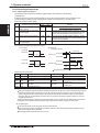
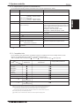
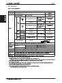
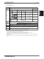
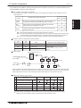
3-4-1-2-3. The effect on connectable quantity of Indoor unit when TB7 or TB3 is used to supply power to the G-50A.
As Indoor unit controller and system controllers share the power supply from the Outdoor unit, the total power consumption of
control use needs following considerations.
Taking the power consumption of the control board of Indoor unit as 1, the equivalent power consumption of the system controller is as follows.
Table 3-4-2 The equivalent power consumption of controllers.
Other system controllers
Indoor unit
1
Central controller
(G-50A)
ON/OFF remote controller
(PAC-YT40ANRA)
System remote controller
(PAC-SF44SRA)
Schedule timer (PAC-YT34STA)
1
0.5
0.5
*In order to ensure the transmission quality in start-up of outdoor unit (or during communication traffic), the number of
system controllers which connected to indoor/outdoor transmission line in the same system, should not exceed3.
CAUTION
Any trouble caused by the failure of the field supplied DC12V power source is not responsible by Mitsubishi Electric Corporation.
When applying Charge and/or Peak-cut function on G-50A, Power Supply Unit (PAC-SC50KUA) is recommended to use. G-50A is possible to
receive power from the one of the Outdoor units, but there is a risk that the failure of power supply from the Outdoor unit will cause G-50A's
function-down on the whole system.
At the air conditioner system of multiple Outdoor units, the connector of CN41 is changed to CN40 at only one of the Outdoor units when TB7 is
used to supply power. When the Outdoor unit failed, the connector at another unit can be changed from CN41 to CN40 to recover the power
supply, but remember to change the CN40 back to CN41 at the failed Outdoor unit.
CONTROLLER
CONTROLLER
Cntr- 18
CNTR-17
3. System
System controller
remote controller
3.
DATA U3
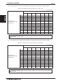
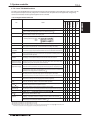
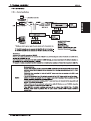
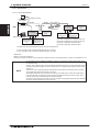
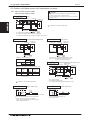
3-4-2. External input/output usage
3-4-2-1. External signal input function
External signal input requires the external I/O adapter (Model: PAC-YG10HA-E) sold separately.
(1) External input
Emergency stop/normal, run/stop and prohibit/enable of local remote controller operation can be controlled for all air
conditioners being controlled by using a voltage (DC12V or DC24V) contact signal from an external source.
(Select with the function select setting)
External signal input function
CONTROLLER
No
Function
No.6
No.7
Do not use external input signal
(factory setting)
Execute emergency stop/normal
with level signal
OFF
OFF
OFF
ON
3
Perform ON/OFF with level signal
ON
OFF
4
Perform ON/OFF, prohibit/enable
with pulse signals.
ON
ON
1
2
Remarks
The local remote controller ON/OFF operations, and the
controller ON/OFF operation and prohibit/enable change
operations will be prohibited during emergency stop.
The local remote controller ON/OFF operations, and the
controller ON/OFF operations and prohibit/enable change
operations will be prohibited.
Set the pulse width while the contact is ON to 0.5 to 1 sec.
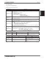
(2) Level signal and pulse signal (DC12V or DC24V)
(A) Level signal
(B) Pulse signal
(Example) for ON/OFF
Contact ON
0.5 to 1 sec
Contact OFF
Stop
Run
Stop
Signal 1 (run)
Contact ON
Contact OFF
0.5 to 1 sec
Contact ON
Contact OFF
Normal Emergency stop Normal
Contact ON
Signal 2 (stop)
Contact OFF
OFF
ON
OFF
The prohibit/enable input is the same.
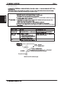
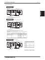
(3)External input specifications
CN2
No.5
No.6
Lead wire
Orange
Yellow
Emergency stop/normal level signal
Emergency stop/normal input
Not used
ON/OFF, level signal
ON/OFF input
Not used
No.7
Blue
Not used
Not used
No.8
Gray
Not used
Not used
No.9
Red
External DC source
ON/OFF, prohibit/enable pulse signal
ON input
OFF input
Local remote controller operation
prohibit input
Local remote controller operation
enable input
(A) For level signal
When the emergency stop/normal signal is selected, the status will change from normal to emergency stop when the
external input signal contact changes from OFF to ON, and will change from emergency stop to normal when the
contact changes from ON to OFF. Emergency stop signal will bring the air conditioners to stop, and canceling the
emergency stop will not automatically reset these units. To go back to the previous operation status, they must be
manually turned back on.
When the ON/OFF signal is selected, the status will change from OFF to ON when the external input signal contact
changes from OFF to ON, and will change from ON to OFF when the contact changes from ON to OFF.
(B) For pulse signal
Even if the ON signal is input during ON, the status will remain ON.
If the local remote controller is prohibited, the ON/OFF operation mode and temperature setting operations by the
local remote controller will be prohibited.
Set the pulse width (contact ON time) to 0.5 to 1 sec.
CONTROLLER
CONTROLLER
Cntr- 19
CNTR-18
3. System
System controller
remote controller
3.
DATA U3
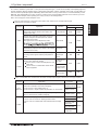
(4)Recommended circuit example
(A) For level signal
CN2
This unit
Red
Orange X1
CN2
X1
Run/stop or
Emergency stop
Orange
Yellow
Blue
Purple
Power supply( 1)
(DC12V or DC24V)
Max.10m
32-3/4ft
This unit
Power supply( 1)
(DC12V or DC24V)
Red
Max.10m
32-3/4ft
X1
X2
Y1
Y2
X1
Y1
Run
Stop
Prohibit
Enable
X2
Y2
CONTROLLER
The contact relay, DC power source, extension cable, etc., must be prepared separately at the site.
The connection cable can be e
10m 32-3/4ft (Use a 0.3mm2 [AWG22] or larger wire.)
Strip the extra cable near the connector, and securely insulate the exposed section with tape, etc.
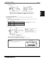
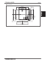
3-4-2-2. External signal output function
External signal output requires the external I/o adapter (Model: PAC-YG10HA-E) sold separately.
(1) External output
When one or more air conditioners are running, the "ON" signal will be output and if a malfunction occurs in one or more air
conditioners, the "Malfunction" signal will be shown.
(2)External output specifications
CN 2
No.1
Lead wire
Green
Details of each terminal
Common (External ground)
No.2
No.3
Black
Brown
ON/OFF
Malfunction/normal
"ON" signal and " Malfunction" signal will
both be output.
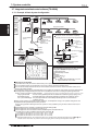
(3)Recommended circuit example
CN2
Diode( 2)
Use Z1 and Z2 relays having the following specifications.
Operation coil
Rated voltage
:DC12V,DC24V
Power Consumption
: 0.9W or less
( 1)Prepare a power supply separately according to the
relay being used. (DC12V or DC24V)
( 2)Always insert a diode on both ends of the relay coil.
Z1
Black
Brown
Z2
Green
Max.10m
32-3/4ft
Power ( 1)
Supply
L1:Run display lamp
L2:Malfunction display lamp
Each element will turn on while ON operation or a malfunction occurs.
The connection cable can be e
10m 32-3/4ft
The relays, lamps, diodes and extension cables, etc, must be prepared separately at the site.
CAUTION
Peel off the label
When connecting the external input/output cables to connector CN2 on the controller, peel off the label on the controller connector section.
Ethernet
M-NET
A
CONTROLLER
CONTROLLER
B
POWER
S
12VDC GND
RS232C
1 CN1 5
1
CN2
9
Cntr- 20
CNTR-19
3. System
System controller
remote controller
3.
DATA U3
3-4-3. LAN connection function
When using the LAN connection function, connect the LAN cable to the Ethernet connector of this device.
Procure the LAN cable at the site, and use an enhanced category 5 UTP cable.
For a description of the IP address setting method, refer to Installation Manual.
LAN is 10 BASE-T Specification.
Ethernet
A
CONTROLLER
POWER
M-NET
B
S
12VDC GND
RS232C
1 CN1 5
1
CN2
9
NOTE
Perform the LAN wiring before installation, and wire up to the body by the same method as wiring the MNET transmission line.
When a LAN is already connected, decide the IP address by consultation with the system administrator and
connect to the LAN body after changing the IP address.
When connecting an LAN connector, space for the connector and wiring is required. Provide this space at
this unit and the rear of the electric box. Refer to Installation Manual.
When the G-50A cover is opened, the LAN status lamp and LAN changeover switch are accessed. For detailed information, refer to Instruction Book.
CONTROLLER
CONTROLLER
Cntr- 21
CNTR-20
3. System controller
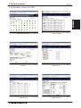
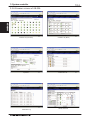
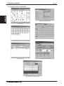
3-4-4. Browser screens of G-50A
81 °F
81 °F
79 °F
81 °F
82 °F
81 °F
81 °F
81 °F
82 °F
81 °F
79 °F
81 °F
81 °F
-- °F
-- °F
Condition List (Block)
Condition List (Overview)
81
CONTROLLER
81 °F
°F
Operation
Malfunction List
79 ˚F
79 ˚F
82 ˚F
Weekly Schedule
Malfunction Log
CONTROLLER
CNTR-21
3.
3. System
System controller
remote controller
DATA U3
3-5. Central controller [GB-50A]
Functions
N623
CENTRAL CONTROLLER
MODEL
WEIGHT
SERIAL No.
DC30/24V;0.13/0.15A
1.1kg / 2
1
/
2
lb
:Not available
Run and stop operation for the air conditioner units
Operation mode
switching
Switches between Cool / Dry / Auto / Fan / Heat.
(Group of LOSSNAY unit : automatic ventilation/ vent - heat
interchange/ normal ventilation)
Operation modes vary depending on the air conditioner unit.
®
Auto mode
mode is
is only
the City
Multi
R2 and
WR2
series
only. series.
Auto
for the
CITY
MULTI
R2
and WR2
Operations
Display
Range of temperature setting
Cool/Dry :
:
Heat
Auto
:
Temperature
setting
in case
case of
of PDFY/PEFY/PFFY-E
using middle-temperature
indoor
(( )) in
indoor
unit. unit.
Range of temperature settings vary depending on model.
A.
A.The
Thecentral
centralcontroller
controllerof
ofGB-50A
GB-50Acombines
combinesWeb
Web
function,
function,which
which enable
enablethe
theair
airconditioner
conditionersystem
system
management
managementon
onaaPC
PCbrowser
browserscreen.
screen.*1.
The
Themanagement
managementeven
evencarried
carriedout
outremotely.
at a long dis*1 Microsoft®
explorer
Ver. 5line.
or later by
tance placeInternet
via public
telephone
Microsoft
Corporation
is needed.
executing
Microsoft®
Internet explorer
Ver.Java
5 or later
by
environment
is needed.(Microsoft
VM Ver.5.0
or
executing
Microsoft Corporation
is needed. Java
later,
or SUN Microsystems’
Java plug-in
Ver.1.4.2
environment
is needed.(Microsoft
VM Ver.5.0
or or
later)
Microsoft
is a registered
trade
markVer.1.4.2
of
later, or
SUN Microsystems'
Java
plug-in
or
Microsoft
Corporation
in the United
States
later). Microsoft
is a registered
trade
markand
of other
countries.
Microsoft Corporation in the United States and other
countries.with integrated centralized control software
B. Together
B.TG-2000A,
Together with
integrated
centralized
control
software
and/or
PLC, many
optional
functions
like
TG-2000A,“Peak-cut”,
and/or PLC,“Energy
many optional
“Charging”,
saving”,functions
“General like
"Charging",management”,
"Peak-cut", "Energy
saving",
"General
equipment
“Scheduling”
etc,
can be
equipment
management",
etc,ofcan
carried
out. Details,
please "Scheduling"
refer to sections
TG-be
carriedand
out.PLC
Details,
please refer to sections of TG2000A
software.
2000A
and PLC
C. One
GB-50A
cansoftware.
control maximum 50 Indoor units
C.(including
One GB-50A
can control
maximumcan
50 Indoor
units
Lossnay).
The TG-2000A
manage
(including 40
Lossnay).
The
TG-2000A
manage
maximum
GB-50As,
therefore
cancan
manage
maximum 2,000
40 GB-50As,
therefore
can manage
maximum
Indoor units
(including
Lossnay).
Lossnay).
maximum
2000 Indoor
units (including
D. Taking
advantage
of GB-50A’s
Web functions,
D.alarming
Taking advantage
of GB-50A's
Web
functions,
E-mail containing
address
and
error code
can
be sent
to appointed
E-mail
address
any
alarming
E-mail
containing
address
and upon
error code
fault
air conditioner
system.upon
This any
can happen
be sent at
to the
appointed
E-mail address
could
release at
standby
and
save operafault happen
the airpersonnel
conditioner
system.
This
tion
cost.
could
release standby personnel and save operation cost.
Fan speed setting
Air flow direction
setting
Permit / Prohibit
local operation
Indoor unit intake
temperature
Models with 4 air flow speed settings: Hi/Mid-2/Mid-1/Low
Models with 3 air flow speed settings: Hi/Mid/Low
Models with 2 air flow speed settings: Hi/Low
Air flow direction angles 100% - 80% - 60% - 40%, Swing,
1: Louver cannot be set.
Air flow direction settings vary depending on the model.
1
Individually prohibit operation of each local remote control
function (Start/Stop, Change operation mode, Set temperature,
Reset filter).
3: When the local remote controller inactivation command is
received from the master system controller, disabled mark
appears in inverted display on the operation screen.
3
Measures the intake temperature of the indoor unit only when
the indoor unit is operating.
When an error is currently occurring on an air conditioner unit,
the afflicted unit and the error code are displayed.
4: When an error occurs, the LED flashes. The operation
monitor screen shows the abnormal unit by flashing it. The
error monitor screen shows the abnormal unit address,
error code and source of detection. The error log monitor
screen shows the time and date, the abnormal unit
address, error code and source of detection.
Error
4
The interlocked system settings can be performed by the master
system controller.
When setting the interlocked system, you can use the ventilation
switch to switch the free plan LOSSNAY settings between "Hi",
"Low" and "Stop".
When setting a group of only free plan LOSSNAY units, you can
switch between "Normal ventilation", "Interchange ventilation"
and "Automatic ventilation".
Ventilation
equipment
By using accessory cables you can set and monitor the
following.
Input
By level signal: "Batch start/stop", "Batch emergency stop"
By pulse signal: "Batch start/stop", "Enable/disable local
remote controller"
Output
"Start/stop", "Error/Normal"
5: Requires the external I/O cable (PAC-YG10HA-E) sold
separately.
External
input/output
5
5
GB-50A needs a PC(field supplied) connected together to monitor and operate the air conditioner system.
External dimension
Unit:mm[in.]
20[25/32]
L-shape metal
(included)
20[25/32] 10
[13/32]
38[1-1/2]
N623
20[25/32]
250[9-7/8 ]
250[9-7/8]
20[25/32]
20[25/32]
CENTRAL CONTROLLER
MODEL
SERVICE REF. GB-50A-E
DC30/24V;0.13/0.15A
1.1kg / 2
1
/
2
lb
MADE IN JAPAN
This device complies with Part15 of the FCCRules.Operation is
subject to the following two conditions:(1)this device may not cause
harmful interference,and(2)this device must accept any interference
received,including interference that may cause undesired operation.
Mounting with L-shape metal
290[11-13/32]
310[12-7/32 ]
INPUT VOLTAGE
(M-NET)
WEIGHT
SERIAL No.
130[5-1/ 8]
CONTROLLER
:Each block
:Collective
ON/OFF
MADE IN JAPAN
This device complies with Part15 of the FCCRules.Operation is
subject to the following two conditions:(1)this device may not cause
harmful interference,and(2)this device must accept any interference
received,including interference that may cause undesired operation.
:Each group
:Each floor
Description
Item
SERVICE REF. GB-50A-E
INPUT VOLTAGE
(M-NET)
:Each unit
35[1-3/8"] DIN Rail
Attachment for DIN Rail (included)
Mounting with DIN Rail
20[25/32]
CONTROLLER
CONTROLLER
CNTR-22
Cntr- 23
3.
3. System
System controller
remote controller
DATA U3
3-5-1. Power supply to GB-50A
GB-50A needs DC power supply of 24~30V for central control transmission use, operating and LAN function use. GB-50A can
have power supply at following 1,2,3 methods.
3-5-1-1. Power supply unit PAC-SC50KUA is the recommended power supplier for GB-50A. The basic scheme is as follows.
For details, please refer to 3-6 Power supply unit PAC-SC50KUA.
M-NET
M-MET
Central controller
GB-50A
CONTROLLER
LAN
UP
POWER SUPPLY UNIT
PAC-SC50KUA
MODEL
POWER R ATIN G
2. 11k g
WEIGHT
SERIAL No.
MITSUBIS
HI ELECT
RIC CORP
ORATION
Power supply unit
PAC-SC50KUA
ME remote
controller
ME remote
controller
M-NET
LOSSNAY unit
ME remote
controller
LOSSNAY remote
controller
Fig. 3-5-1 GB-50A and PAC-SC50KUA basic scheme.
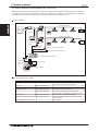
3-5-1-2. Power supply of DC 30V from connector of TB7 or TB3 of Outdoor unit.
3-5-1-2-1. TB7 of Outdoor unit.
As shown at Fig. 3-5-2, GB-50A receives power supply of DC 30V from the connector of TB7 at the R410A Outdoor unit.
In the case, one of the Outdoor units should change its power supply switch of CN41 to CN40.
Central control
R410A
Outdoor unit
transmission line
Indoor/outdoor transmission line
CN41
CN40
Indoor/outdoor transmission line
CN41
Fig. 3-5-2 GB-50A, TB7 power supply
CONTROLLER CONTROLLER
CNTR-23
Cntr- 24
3. System
System controller
remote controller
3.
DATA U3
3-5-1-2-2. TB3 of Outdoor unit.
GB-50A can also receive power supply from TB3 connector of the R410A or R407C, R22 Outdoor unit. Yet, the Outdoor unit
down will lead down to GB-50A too. The kind of connection is possible but is not recommended for an air conditioner system
of multiple Outdoor units.
Indoor/outdoor transmission line
TB3
CONTROLLER
CN41
Fig.3-5-3 GB-50A, TB3 power supply
3-5-1-2-3. The effect on connectable quantity of Indoor unit when TB7 or TB3 is used to supply power to the GB-50A.
As Indoor unit controller and system controllers share the power supply from the Outdoor unit, the total power consumption of
control use needs following considerations.
Taking the power consumption of the control board of Indoor unit as 1, the equivalent power consumption of the system controller is as follows.
Table 3-5-1 The equivalent power consumption of controllers.
Other system controllers
Indoor unit
1
Central controller
(GB-50A)
3
ON/OFF remote controller
(PAC-YT40ANRA)
System remote controller
(PAC-SF44SRA)
Schedule timer (PAC-YT34STA)
1
0.5
t-up of outdoor unit (or during communication traffic), the number of
system controllers which connected to indoor/outdoor transmission line in the same system, should not exceed3.
CAUTION
When applying Charge and/or Peak-cut function on GB-50A, Power Supply Unit (PAC-SC50KUA) is recommended to use. GB-50A is possible to
receive power from the one of the Outdoor units, but there is a risk that the failure of power supply from the Outdoor unit will cause GB-50A's
function-down on the whole system.
At the air conditioner system of multiple Outdoor units, the connector of CN41 is changed to CN40 at only one of the Outdoor units when TB7 is
used to supply power. When the Outdoor unit failed, the connector at another unit can be changed from CN41 to CN40 to recover the power
supply, but remember to change the CN40 back to CN41 at the failed Outdoor unit.
CONTROLLER CONTROLLER
Cntr- 25
CNTR-24
3.
3. System
System controller
remote controller
DATA U3
3-5-2. External input/output usage
CN2
3-5-2-1. External signal input function
External signal input requires the external I/O adapter (Model: PAC-YG10HA-E) sold separately.
(1) External input
External signal input function
No
Do not use external input signal
(factory setting)
Execute emergency stop/normal
with level signal
1
2
3
Perform ON/OFF with level signal
4
Perform ON/OFF, prohibit/enable
with pulse signals.
CONTROLLER
Emergency stop/normal, run/stop and prohibit/enable of local remote controller operation can be controlled for all air
conditioners being controlled by using a voltage (DC12V or DC24V) contact signal from an external source.
(Select the function on the Initial Setting Web or the Initial Setting Tool)
Remarks
The local remote controller ON/OFF operations, and the
controller ON/OFF operation and prohibit/enable change
operations will be prohibited during emergency stop.
The local remote controller ON/OFF operations, and the
controller ON/OFF operations and prohibit/enable change
operations will be prohibited.
Set the pulse width while the contact is ON to 0.5 to 1 sec.
(2) Level signal and pulse signal (DC12V or DC24V)
(A) Level signal
(B) Pulse signal
(Example) for ON/OFF
Contact ON
0.5 to 1 sec
Contact OFF
Stop
Run
Stop
Signal 1 (run)
Contact ON
Contact OFF
0.5 to 1 sec
Contact ON
Contact OFF
Normal Emergency stop Normal
Contact ON
Signal 2 (stop)
Contact OFF
OFF
ON
OFF
The prohibit/enable input is the same.
(3)External input specifications
CN2
No.5
No.6
Lead wire
Orange
Yellow
Emergency stop/normal level signal
Emergency stop/normal input
Not used
ON/OFF, level signal
ON/OFF input
Not used
No.7
Blue
Not used
Not used
No.8
Gray
Not used
Not used
No.9
Red
External DC source
ON/OFF, prohibit/enable pulse signal
ON input
OFF input
Local remote controller operation
prohibit input
Local remote controller operation
enable input
(A) For level signal
When the emergency stop/normal signal is selected, the status will change from normal to emergency stop when the
external input signal contact changes from OFF to ON, and will change from emergency stop to normal when the
contact changes from ON to OFF. Emergency stop signal will bring the air conditioners to stop, and canceling the
emergency stop will not automatically reset these units. To go back to the previous operation status, they must be
manually turned back on.
When the ON/OFF signal is selected, the status will change from OFF to ON when the external input signal contact
changes from OFF to ON, and will change from ON to OFF when the contact changes from ON to OFF.
(B) For pulse signal
Even if the ON signal is input during ON, the status will remain ON.
If the local remote controller is prohibited, the ON/OFF operation mode and temperature setting operations by the
local remote controller will be prohibited.
Set the pulse width (contact ON time) to 0.5 to 1 sec.
CONTROLLER CONTROLLER
CNTR-25
Cntr- 26
3.
3. System
System controller
remote controller
DATA U3
3-5-2-1. External signal input function
(4)Recommended circuit example
(A) For level signal
CN2
CONTROLLER
5
6
7
8
This unit
CN2
Red
9
Orange X1
X1
Run/stop or
Emergency stop
Power supply( 1)
(DC12V or DC24V)
Max.10m
32-3/4ft
9
Red
5
6
7
8
Orange
Yellow
Blue
Purple
This unit
Power supply( 1)
(DC12V or DC24V)
X1
X2
Y1
Y2
Max.10m
32-3/4ft
X1
Y1
X2
Y2
Run
Stop
Prohibit
Enable
The contact relay, DC power source, extension cable, etc., must be prepared separately at the site.
The connection cable can be extended up to 10m 32-3/4ft . (Use a 0.3mm2 [AWG22] or thicker wire.)
Strip the extra cable near the connector, and securely insulate the exposed section with tape, etc.
3-5-2-2. External signal output function
External signal output requires the external I/o adapter (Model: PAC-YG10HA-E) sold separately.
(1) External output
When one or more air conditioners are running, the “ON” signal will be output and if a malfunction occurs in one or more air
conditioners, the “Malfunction” signal will be shown.
(2)External output specifications
CN 2
No.1
Lead wire
Green
Details of each terminal
Common (External ground)
No.2
No.3
Black
Brown
ON/OFF
Malfunction/normal
" ON" signal and " Malfunction" signal will
both be output.
(3)Recommended circuit example
CN2
Diode( 2)
Use Z1 and Z2 relays having the following specifications.
Operation coil
Rated voltage
:DC12V,DC24V
Power Consumption
: 0.9W or less
( 1)Prepare a power supply separately according to the
relay being used. (DC12V or DC24V)
( 2)Always insert a diode on both ends of the relay coil.
Z1
Black
Brown
Z2
Green
Max.10m
32-3/4ft
Power ( 1)
Supply
L1:Run display lamp
L2:Malfunction display lamp
Each element will turn on while ON operation or a malfunction occurs.
The connection cable can be extended up to 10m 32-3/4ft
The relays, lamps, diodes and extension cables, etc, must be prepared separately at the site.
CONTROLLER CONTROLLER
CNTR-26
Cntr- 27
3. System
System controller
remote controller
3.
DATA U3
3-5-3. LAN connection function
Connect the LAN cable to the LAN connector of this device.
Procure the LAN cable at the site, and use an enhanced category 5 UTP cable.
For a description of the IP address setting method, refer to Installation Manual.
LAN is 10 BASE-T Specification.
The maximum wiring length from HUB to GB-50A is 100m [328ft].
GB-50A is connected to the monitoring PC via HUB.
Perform the LAN wiring before installation, and wire up to the body by the same method as wiring the MNET transmission line.
When a LAN is already connected, decide the IP address by consultation with the system administrator and
connect to the LAN body after changing the IP address.
Space for the connector and wiring is required. Refer to Installation Manual.
CONTROLLER CONTROLLER
Cntr- 28
CNTR-27
CONTROLLER
NOTE
3. System controller
CONTROLLER
3-5-4. Browser screens of GB-50A
81 °F
81 °F
81 °F
79 °F
81 °F
82 °F
81 °F
81 °F
81 °F
82 °F
81 °F
79 °F
81 °F
81 °F
-- °F
-- °F
Condition List (Block)
Condition List (Overview)
81
°F
Operation
Malfunction List
79 ˚F
79 ˚F
82 ˚F
Weekly Schedule
Malfunction Log
CONTROLLER
CNTR-28
3.
3. System
System controller
remote controller
DATA U3
3-6. Power supply unit [PAC-SC50KUA]
PAC-SC50KUA supplies DC powers of 24V and 12V at TB2 and TB3 respectively; the former is for central control transmission
use and the latter is for G-50A operation and LAN function use.
3-6-1. When using PAC-SC50KUA as the power supplier for system controller, the capacity for system controller is considered
as follows.
Central control
transmission line
Main SC
Indoor/outdoor transmission line
CONTROLLER
TB7
Add : 000
CN41
(DC12V)
TB3
TB2
(DC24V)
Power supply unit
PAC-SC50KUA
Indoor/outdoor transmission line
TB7
Sub SC
CN41
Add : 201
SC : System Controller
Lossnay
Lossnay can have its own Lossnay remote
controller, but the total quantity of the controllers
is limited.
Fig. 3-6-1 Equivalent power consumption of controllers
In this case, pay attention to leave the power supply switch connector on CN41 of the Outdoor unit as the factory setting
before shipment.
Taking the power consumption of the control board of Indoor unit as 1, the power consumption of various controllers is rated at
Table 3-6-1.
Table 3-6-1 Equivalent power consumption of controllers
Other system controllers
Central controller
G-50A
GB-50A
0.5
3
ON/OFF remote controller
(PAC-YT40ANRA)
1
System remote controller
(PAC-SF44SRA)
Schedule timer
(PAC-YT34STA)
Remote controllers
ME remote controller
(PAR-F27MEA)
LOSSNAY remote controller
(PZ-52SF)
0.25
0.5
PAC-SC50KUA is capable to supply equivalent power up to 6, therefore the maximum connectable number of system controllers is as follows.
Table 3-6-2 Max. connectable quantity of controller when using PAC-SC50KUA
Other system controllers
Central controller
G-50A
2 units
(Note 1)
GB-50A
2 units
ON/OFF remote controller
(PAC-YT40ANRA)
6 units
System remote controller
(PAC-SF44SRA)
Schedule timer
(PAC-YT34STA)
12 units
Remote controllers
ME remote controller
(PAR-F27MEA)
LOSSNAY remote controller
(PZ-52SF)
24 units
(Note 1) Due to its current limit of DC12V supplying, the PAC-SC50KUA can supply power for maximum 2 G-50As.
As the air conditioner control system may combine all kinds of system controllers, the total power consumption of system controllers need to count with Table 3-6-1.
For example, the controller system contain 1 G-50A, 2 ON/OFF remote controllers (PAC-YT40ANRA), 1 schedule timer (PACYT34STA), 6 Lossnay remote controllers connected at centralized control communication line.
then the total power consumption is
1x0.5+2x1+1x0.5 +6x0.25 = 4.5 6.
One PAC-SC50KUA is therefore enough. The total power consumption should not exceed 6.
CONTROLLER CONTROLLER
CNTR-29
Cntr- 30
3.
3. System
System controller
remote controller
DATA U3
3-6-2. When supply power to 1 G-50A, the PAC-SC50KUA can supply power to other system controllers as follows.
Table 13-2-3 Connectable number of system controller when 1 G-50A is used.
V : Connectable
CONTROLLER
Total number of ON/OFF remote controller (AN)
Total number of
System remote controller
Schedule timer
0
1
2
3
4
5
0
-
V
V
V
V
V
1
V
V
V
V
V
V
2
V
V
V
V
V
3
V
V
V
V
V
4
V
V
V
V
5
V
V
V
V
6
V
V
V
7
V
V
V
8
V
V
9
V
V
10
V
11
V
6
12
CAUTION
When applying Charge and/or Peak-cut function on G-50A, Power Supply Unit (PAC-SC50KUA) is recommended to use. G-50A is possible to
receive power from one of the Outdoor units, but there is a risk that the failure of power supply from the Outdoor unit will cause G-50A's functiondown on the whole system.
3-6-3. When supply power to 1 GB-50A, the PAC-SC50KUA can supply power to other system controllers as follows.
Table 13-2-4 Connectable number of system controller when 1 GB-50A is used.
V : Connectable
Total number of ON/OFF remote controller (AN)
0
Total number of
System remote controller
Schedule timer
1
2
3
V
V
V
V
V
0
-
1
V
2
V
V
V
3
V
V
4
V
V
5
V
6
V
4
5
6
7
8
9
10
11
12
CAUTION
When applying Charge and/or Peak-cut function on GB-50A, Power Supply Unit (PAC-SC50KUA) is recommended to use. GB-50A is possible to
receive power from one of the Outdoor units, but there is a risk that the failure of power supply from the Outdoor unit will cause GB-50A's functiondown on the whole system.
CONTROLLER CONTROLLER
CNTR-30
Cntr- 31
3. System
System controller
remote controller
3.
DATA U3
External dimension
Unit:mm[in.]
265[10-7/16 ]
150[ 5-29/32]
59.2[ 2-11/32 ]
240 [9-7/16]
CONTROLLER
225 [8-27/32 ]
UP
TB3
POWER SUPPLY UNIT
MODEL
TB2
PAC-SC50KUA
POWER RATING
WEIGHT
SERIAL No.
2.11kg
MITSUBISHI ELECTRIC CORPORATION
Cable fixture
TB1
Cable fixture
CONTROLLER CONTROLLER
Cntr- 32
CNTR-31
3.
3. System
System controller
remote controller
DATA U3
3-7. Integrated centralized control software [TG-2000A]
3-7-1. Example of Basic System Configuration.
Single-phase 208/230V
M-NET
CONTROLLER
Charge
license
Input
G-50A
Web
monitor
license
12VDC
Single-phase 208/230V
UP
POWER SUPPLY UNIT
MODEL
PAC-SC50KUA
POWER R ATIN G
2. 11k g
WEIGHT
SERIAL No.
MITSUBISHI
Schedule
license
ELECTRIC
CORPORATIO
N
Power supply unit
PAC-SC50KUA
3-phase 208/230V
(3-wire)
Indoor unit system
watt-hour meter
Compatible with TG-2000A Ver. 4.10 and higher
The electric amount count software or separately
procured parts must be used with the designated PLC.
Indoor unit
watt-hour meter
power source
Outdoor unit system
watt-hour meter
RS-232C
Indoor unit
watt-hour meter
Outdoor unit system
watt-hour meter
RS-485
Converter
Uninterruptive
power supply (UPS)
Central controller
personal computer
TG-2000A
Indoor unit system
watt-hour meter
PLC (with electric amount count
software)
Uninterruptible
power supply (UPS)
Integrated
centralized control
software installation
Central control
personal computer
TG-2000A
Integrated centralized control
software installation
The TG-2000A can realize the following functions
using the G-50A/GB-50A option (license).
Main features of TG-2000A
Operation/monitor
Annual/weekly schedule
Charge
Energy saving 1
Peak cut 1
1: Compatible with TG-2000A Ver. 4.10 and
higher, G-50A Ver. 2.51 or later.
1 Up to 2000 indoor units (40 G-50A or GB-50A units) can be operated and monitored simultaneously.
2 The air-conditioner layout can be displayed on the screen, making control and operation easier.
3 The annual and weekly schedules can be set. Two schedules, such as the summer master and winter master, can be
saved in the weekly schedule.
4 Air-conditioning charges can be calculated based on the multiple air-conditioner usage results. The power apportionment
5
6
7
8
percentage data and apportioned power rate can be calculated for each indoor unit using the power apportionment
Power apportionment charging is not possible with the old model, A control or K control.
function, and can be output as a CSV format file.
Charging without WHM
: The user manually inputs the power rate to calculate the air-conditioning charges. (Using a tool)
RS-485 WHM charging
: The RS-485 WHM value is automatically tabulated to calculate the air-conditioning charges.
PLC + pulse WHM charging : The pulse output WHM value is automatically tabulated by the PLC to calculate the airconditioning charges.
Energy saving operation is possible using the "ON/OFF", "set temperature change", "fan operation changeover" and
"performance save operation (60% to 90%)" functions.
Energy saving operation matching the amount of power in use is possible by using the PLC's electric amount count
software.
Night Set-Back function operation is possible with schedule settings. 1,4
General equipment can be operated and monitored. 2
General equipment can be schedule-controlled when using PAC-YG21CDA with PLC.
For details of PLC refer to Installation Manual of PAC-YG21CDA. 3
1: Compatible with TG-2000A Ver. 4.10 or later, G-50A Ver. 2.51 or later.
2: Compatible with TG-2000A Ver. 4.30 or later, G-50A Ver. 2.51 or later.
3: Compatible with TG-2000A Ver. 4.60 or later, G-50A Ver. 2.70 or later.
4: With Night Set-Back function, the CITY MULTI system can run at heating mode with target temperature set to 54
12
schedule control. This function can protect the room from dropping down to extremely low temperature at mid-night.
CONTROLLER CONTROLLER
under
CNTR-32
Cntr- 33
3. System
System controller
remote controller
3.
DATA U3
3-7-2. List of TG-2000A functions
The data for each G-50A/GB-50A can be grouped and used to control the operation of up to 2000 units in floor or block units, etc.,
from the personal computer screen. By using a PLC or a watt-hour meter, the power rate can be apportioned, energy saving
control can be executed, and other general equipment can be controlled.
List of integral software functions
G-50A/GB-50A license
The operation mode can be switched between COOL, DRY, FAN, AUTO and
HEAT for all floors or in block, floor or group units.
V
Temperature setting
The room temperature can be set for all floors or in block, floor or group units.
Set temperature range COOL / DR
HEAT
AUTO
Depend on unit type
V
Fan speed
The fan speed can be set to four stages for all floors or in block, floor or group units.
V
Air direction
The air direction can be set in four vertical directions or to swing for all floors or in block,
floor or group units.(The selectab le air direction differs according to the model.)
V
Interlocked unit ON/OFF
(LOSSNAY)
If there is an interlocked unit (LOSSNAY), the unit can be turned ON (strong/weak) or OFF for all floors
or in block, floor or group units. (Note that the ventilation mode cannot be selected for interlocked units.)
V
Local operation
prohibit
The items for which operation with the local remote controller are to be prohibited can be selected for
all floors or in block, floor or group units. (The items that can be prohibited are ON/OFF, operation mode,
set temperature and filter sign reset.)
V
Annual / weekly
schedule
The annual/weekly schedule function can be used by registering the license.
Two settings, such as seasonal settings for summer and winter, can be saved.
V
Power rate
apportionment charging
(power rate manual input)
By registering the G-50A unit license number, the power rate apportionment percentage data for
each indoor unit can be output in CSV format. The power rate for each tenant can be easily
calculated by having each user input the power rate manually.
V
V
Power rate
apportionment charging
An RS-485 watt-hour meter is connected to calculate the air-conditioning charges based on the
amount each tenant's air-conditioner has operated. Two charging rates can be applied per day.
V
V
By using a PLC (with electric amount count software) and a watt-hour meter with pulse transmitter,
the air-conditioning charges can be calculated based on the amount each tenant's air-conditioner has
operated.Up to five charging rates can be applied per day. 1
History
Up to 3000 items for the error history and up to 10000 items for operation history can be saved.
Each history file can be output as a daily report or monthly report in CSV format.
The operation history consists only of the operations carried out with the TG-2000A, and is limited to some limited operation items.
V
Operation time monitor
The cumulative operation time of each indoor unit can be viewed or output as a CSV format file.
(This function is valid only when the charging function license is registered.)
V
Filter sign display
mask
Automatic display of the filter sign can be disabled. (System batch.)
In this case, the filter sign state is confirmed with manual operations .
V
Energy saving
control 1
Energy saving operation is possible using the "ON/OFF", "set temperature change", "fan operation
changeover" and "performance save operation" functions.
V
Energy saving
(peak cut) 1
Energy saving operation matching the amount of power in use is possible.
(PLC (with electric amount count software) and watt-hour meter with pulse transmitter are required.)
V
Night Set-Back function 1,4
V
Set temperature
limit 1
The set temperature lower limit can be set for cooling and the upper limit for heating.
(Valid only when PAR-F27MEA is used.)
V
Control other general
equipment
It is possible to control other general equipment on ON/OFF operation / monitoring / Alarm /
scheduling, if TG-2000A combines PLC installed with PLC software PAC-YG21CDA. 2
V
Setting inter-lock with CITYMULTI indoor units is possible.
(Table setting tool for input/output definition is needed.) 3
V
1: Compatible with TG-2000A Ver. 4.10 or later, G-50A Ver. 2.51 or later.
2: Compatible with TG-2000A Ver. 4.30 or later, G-50A Ver. 2.51 or later.
3: Compatible with TG-2000A Ver. 4.60 or later, G-50A Ver. 2.70 or later.
4: With Night Set-Back function, the CITY MULTI system can run at heating mode with target temperature set to 54
This function can protect the room from dropping down to extremely low temperature at mid-night.
12
V
V
V
V
V
V
under schedule control.
CONTROLLER CONTROLLER
Cntr- 34
CNTR-33
CONTROLLER
Operation modes
PLC for
general equipment
V
Energy saving
(peak cut)
V
The general equipment can be turned ON and OFF.
( A PLC and the general equipment control PLC software required.) 2
Energy saving
The units can be turned ON and OFF for all floors or in block, floor or group units.
Schedule
Details
Charge
ON/OFF
Web monitor
Item
3.
3. System
System controller
remote controller
DATA U3
CONTROLLER
3-7-3. Browser screens of TG-2000A
Weekly schedule screen
Floor screen
Annual schedule screen
Block screen
All floor screen
Operation setting screen
Air-conditioning charge screen
CONTROLLER
CONTROLLER
CNTR-34
Cntr- 35
3. System remote controller
3. System controller
DATA U3
3-7-4. Requirements (system recommendations)
We recommend the following software and hardware when using this application (TG-2000A).
Item
Requirement
Recommended
PC
PC/AT interchangeable machine
Operation check completed, using IBM, and DELL
CPU
Within 1000 indoor units :
Pentium 4 1.8GHz or faster
1001 indoor units or over :
Pentium 4 1.8GHz or faster
(Case of temp, trend use : 2.8GHz or faster.)
Pentium 4
Memory
128MB or more (In Windows XP : 256MB or more)
512MB or more
HDD
6GB or more (2GB or more of C drive free
space necessary)
4GB or more of C drive free space necessary
When using the trend function, the drive used for automatic output must have the following free space according to the number of groups.
200 groups = 2GB, 500 groups = 5GB,
1000 groups = 10GB, 2000 groups = 20GB
Storage device
FDD, CD-ROM drive
Devices other than those shown at the left may also
be installed.
Resolution
Serial port
1024 768 or higher, 65536 colors or more
1 port or more
LAN
OS
Internal LAN (10/100 Mbps)
Windows XP Professional
Windows 2000 Professional
Service Pack 2 and above
Other
Computer must be dedicated for this use
(TG-2000A).
2.8GHz or faster
1
English version only
Personal computer must support each OS.
1 Purchase the option, or use the equipment recommended for the personal computer when purchasing the personal computer.
3-7-5. Compatible Units
The TG-2000A has two main functions: centralized control of air conditioners and cost accounting. However, not all
functions are available with all air conditioners. (TG-2000A Ver.4.80 or later)
Table: Compatible units and function list ( : supported, : Certain restrictions apply, : Not supported)
Function
Model
Control/
Maintenance
Charging (Billing)
without WHM
Charging (Billing) with WHM
Y-Series
1
R2-Series
1
WR2-Series
1
WY-Series
1
S-Series
1
Indoor unit
2
LOSSNAY
4
OA processing unit
"A" control type 3
1
"K" control type
3
1
(Adapter required)
1
(Converter required)
1 : Can be calculated for each charging block. May not be available with some older models.
2 : Indoor unit models before Free Plan models do not support a charge apportioning billing method based on
the “capacity save”. The existence of even a single unit of those types in the system requires that the
method of charge apportioning billing be set to either “Thermo on time” or “Fan operation time”.
3 : Not all of the A-control and K-control units support these functions. The calculation of the charge for the
auxiliary heater may not be handled by these units.
4 : LOSSNAY groups to which the remote controller is connected support the charging system.
CONTROLLER
CONTROLLER
Cntr- 36
CNTR-35
CONTROLLER
Required when using RS-485 communication WHM
3.
controller
3. System
System remote
controller
DATA U3
3-8. Electric amount count software [PAC-YG11CDA]
MITSUBISHI ELECTRIC offers charging function for the air conditioner system. Detailed output of every indoor on electricity
consumption of air-conditioning is available. The electricity consumption of air-conditioner is counted based on the refrigerant
consumption of every indoor unit, which makes the proportion of electricity consumption precise.
CONTROLLER
System example
Single-phase 208/230V
Charge
license
Input
G-50A
DC12V
Single-phase 208/230V
Power supply unit
3-phase 208/230V
(3-wire)
Outdoor unit system
watt-hour meter
Indoor unit system watt-hour meter
Indoor unit system watt-hour meter
PLC (Pulse counting software installed)
Uninterrupted
power source (UPS)
PC for TG-2000A
Install TG-2000A software
Necessary parts for the system
Name (Model name)
PC for central control
Manufacturer
PC/AT convertible unit
TG-2000A
Charge license
Web monitor license
PLC
MITSUBISHI ELECTRIC
MITSUBISHI ELECTRIC
MITSUBISHI ELECTRIC
MITSUBISHI ELECTRIC
PAC-YG11CDA
Watt-hour meter with pulse oscillator
MITSUBISHI ELECTRIC
MITSUBISHI ELECTRIC
Uninterrupted power source (UPS)
Remarks
Confirmed operation of IBM, DELL, Hp Compaq.
For details, refer to G-50A Technical Manual.
Requires for each G-50A/GB-50A.
Requires for each G-50A/GB-50A.
PLC for pulse counting connects maximum 5 sets.
For details, refer to Installation Manual of PAC-YG11CDA.
For details, refer to G-50A Technical Manual.
For the specification of the watt-hour meter, refer to G-50A
Technical Manual.
Field supplied.
CONTROLLER CONTROLLER
Cntr- 37
CNTR-36
3.
3. System
System controller
remote controller
DATA U3
3-9. PLC software for general equipment [PAC-YG21CDA (SW-PLC-GE)]
MITSUBISHI ELECTRIC's Air Conditioner control system can combine control of general equipment like lighting, air conditioners from others, and so on.
Functions on general equipment : On/Off operation, alarm, monitoring, scheduling.
System example
license
Input
CONTROLLER
M-NET *1
LAN
G-50A
*1.MITSUBISHI ELECTRIC Air Conditioner network.
M-NET *1
UP
PAC-SC50KUA
Power supply unit
Free contact
(input and output signal)
G-50A
Pulse or Level output
PLC
Lighting
Level input
PC for TG-2000A
Other manufacturer's packaged
air-conditioning units
TG-2000A installed.
PLC software for general equipment
PAC-YG21CDA [SW-PLC-GE]
Other manufacturer's fan coil units
Chiller/heat source
machine
Necessary parts for the system
Materials (model names)
PC for central control
Maker
PC/AT compatible
TG-2000A
Web monitor license
PLC for general equipments license
PLC
PAC-YG21CDA [SW-PLC-GE]
MITSUBISHI ELECTRIC
MITSUBISHI ELECTRIC
MITSUBISHI ELECTRIC
MITSUBISHI ELECTRIC
MITSUBISHI ELECTRIC
Remarks
Confirmed operation of IBM, DELL, Hp Compaq.
For details, refer to G-50A Technical Manual.
Use Ver.4.60 or later (Use G-50A's Ver. 2.70 or later)
Requires for each G-50A/GB-50A.
Table-setting of input/output is necessary.
Make sure DI board and DO board are mounted.
For details, refer to G-50A Technical Manual.
CONTROLLER CONTROLLER
Cntr- 38
CNTR-37
3.
3. System
System controller
remote controller
DATA U3
3-10. BACnet® interface [PAC-YG31CDA] [SW-BACnet]
CITY MULTI® can easily combine into a Building Management System (BMS) via the BACnet® interface software and a PC.
BACnet® is an opened transmission protocol widely used at BMS, and related equipment control. CITY MULTI® is therefore
compatible with large-scaled BMS management via BACnet®.
One BACnet® interface software and PC serves up to 10 G-50As/GB-50As.
CONTROLLER
System example
Central
monitor
BACnet
BMS
®
M-NET
LAN
WHM
WHM
G-50A
BACnet interface software
PAC-YG31CDA (SW-BACnet)
®
UP
M-NET
PAC-SC50KUA
Power supply unit
G-50A
Web
Browser
(Optional)
TG-2000A
(Optional)
Communication items at BACnet® Interface Software PAC-YG31CDA (SW-BACnet)
On/Off
Mode
Fan speed
Air direction
Set temp.
Filter sign reset
Operation Prohibit local On/Off
Prohibit local Mode
Prohibit local Filter sign reset
Prohibit local Set temp.
On/Off
Mode
Fan speed
Air direction
Set temp.
Filter sign
Indoor temperature
State
Prohibit local On/Off
Monitoring
Prohibit local Mode
Prohibit local Filter sign reset
Prohibit local Set temp.
Forced Off
Use a dedicated PC with the BACnet® interface software (PAC-YG31CDA).
Alarm signal
Error code
Communication state
CONTROLLER CONTROLLER
CNTR-38
Cntr- 39
3. System
System remote
controller
3.
controller
DATA U3
3-11. PLC software for demand input [PAC-YG41CDA]
MITSUBISHI ELECTRIC's CITY MULTI® has its intelligent way to carry out peak-cut control while maximizing the air conditioning effect.
System example
The registration of
License energy saving control
or peak cut control is
necessary.
CONTROLLER
- Energy saving setting
- Monitoring of current energy saving
state
.
- Set temperature control (
- Fan (thermostat OFF) control
- Stopping control
G-50A
PC for TG-2000A
Collects daily
power
consumption
Collects current
daily consumption
(every per minute)
- Capacity saving control
(60/70/80/90%)
Watt-hour
meter
PLC PAC-YG11CDA
(Pulse counting
software installed)
Counts for electric power pulse
or
Requires to execute the peak cut control.
Either method should be used.These methods cannot be used together.
Demand
controller
PLC
(PLC software
for demand input)
Contact input (4 levels max.)
If the quantity of G-50A exceeds 11 sets, one set of PLC is required
for each 10 sets of PLC.
Necessary parts for the system
Name (Model name)
PC for central control
Maker
PC/AT convertible unit
TG-2000A
G-50A/GB-50A
Energy saving control (peak cut) license
Web monitor license
MITSUBISHI ELECTRIC
MITSUBISHI ELECTRIC
MITSUBISHI ELECTRIC
MITSUBISHI ELECTRIC
Remarks
Confirmed operation of IBM, DELL, Hp Compaq.
For details, refer to G-50A Technical Manual.
Use Ver.4.6 or later.
Use Ver.2.6 or later.
Requires for each G-50A/GB-50A.
Requires for each G-50A/GB-50A.
CONTROLLER
CONTROLLER
CNTR-39
Cntr- 40
3.System
Systemcontroller
remote controller
3.
DATA U3
Applying the energy saving setting from the integrated centralized control software TG-2000A or Initial setting Web allows
conducting the energy saving control by the indoor/outdoor units or peak-cut control by using PLC.
Energy saving
control
Item
Indoor unit control
Content
The TG-2000A or Initial setting Web sets the f ollowing energy saving items and energy saving
time to G-50A/GB-50A per operation block. G-50A/GB-50A conducts energy saving operation to
the indoor units with the set detail.
Temperature control (
Fan control (Thermostat ON)
Stopping control
For the block with temperature difference between set and inlet temperature exceeding the set,
the energy saving control set at level 0 is not applied.
The TG-2000A or Initial setting Web sets the following energy saving items and energy saving
time to G-50A/GB-50A per outdoor unit and the set G-50A/GB-50A conducts the energy saving
operation for the outdoor unit.
CONTROLLER
.
Outdoor unit
control 2
Peak cut control Power consumption
monitoring method
Demand controller
method
Monitoring of
energy saving
control
status/history1
Control status
Daily report
Monthly report
Connecting the watt-hour meter (PLC) allows conducting energy saving operation meeting the
power consumption. The control object and detail are same as that of the energy saving rotated
control. One set of the watt-hour meter can be set for each G-50A/GB-50A.
Energy-saving control that is appropriate to the current demand level is performed by receiving
the demand level contact signal from the demand controller using the PLC.
An installation of demand input PLC software is necessary to use the PLC.
Control targets and control content of this method are the same as those of the energy-saving control.
Each PLC unit can control up to ten G-50A units to be on the energy-saving control.
During the energy saving control, the energy saving mark is displayed on the air conditioner
group icon of Web, integrated software.
Daily power consumption and control level can be monitored by the integrated software. G-50A/GB-50A
can hold the data for 3 days max. including that of today, yesterday and the day before yesterday.
Monthly power consumption can be monitored by the integrated software (for 62 days max.).
The integrated software monitors from PLC for display and storing.
1; Daily Report and Monthly Report are functions that are enabled only when registering the "Energy-saving peak cut control license."TG2000A must always be kept in operation to gather data on energy-saving control status and the operation history. The auto-output CSV
files in the Daily Report and Monthly Report can be saved for two years in the appropriate folders.
2; For Mr. Slim units, apply Outdoor Unit Control function only to Inverter type units.
CONTROLLERCONTROLLER
Cntr- 41
CNTR-40
3.
controller
3. System
System remote
controller
DATA U3
3-12. LonWorks® interface [LMAP03U]
CITY MULTI® can easily combine into a Building Management System (BMS) via the LONWORKS and M-NET adapter
LMAP03U. LONWORKS is an opened transmission protocol widely used at BMS and related equipment control.
CITY MULTI® is therefore compatible with large-scaled BMS management via LONWORKS .
®
®
®
One LMAP03U serves up to 50 indoor units. (CITY MULTI , Mr. Slim , and LOSSNAY .)
®
®
®
System example
CONTROLLER
LMAP
Building management system
Protocol : LONWORKS
®
LMAP
Lighting
Elevator
Communication items at LONWORKS
®
and M-NET Adapter LMAP03U
On/Off
Mode
Set point from network (Set temp.)
Fan speed
On/Off
Mode
Set point from network (Set temp.)
Fan speed
Thermo On/Off
State
Indoor temperature
Monitoring Alarm signal
Operation
Prohibit local On/Off
Prohibit local Mode
Prohibit local Set temp.
Prohibit local On/Off
Prohibit local Mode
Prohibit local Set temp.
Batch Off
CONTROLLER CONTROLLER
Cntr- 42
CNTR-41
3. System
System controller
remote controller
3.
DATA U3
Environment specification
Item
Description
Connected Equipment
MITSUBISHI ELECTRIC
Multiple split-type air conditioners
Split-type air conditioners
Heat recovery ventilators
CITY MULTI ®
Mr.SLIM ®
LOSSNAY®
Number of Units
LMAP can control 50 indoor units (Including
(including LOSSNAY
LOSSNAY)®)
Neuron CHIP
TMPN3150 (10MHz)
Network Transceiver
Performance
FTT-10A (Free Topology 78kbps)
Average communication capacity
2.5 inputs/second
Peak communication capacity
50 inputs/second (for one second)
The proper communication is not obtainable when communication intervals exceed its performance, assure sufficient intervals.
ACK Service is recommended for the network service.
Detailed specifications for the LONWORKS network can be found in " FTT-10A Free Topology Transceiver User's Guide " by Echelon Corporation.
<LMAP03U Network Variables>
Network Variables
Request On/Off
nv1n nviOnOff_n
nv2n
nvoOnOff_n
On/Off state
Request Mode
nv3n nviMode_n
nv4n
nvoMode_n
Mode state
Setpoint from network
(set temp.)
nv5n nviSetPoint_n
nv6n
nvoSetPoint_n
Setpoint state
(set temp.)
Request Fanspeed
nv7n nviFanSpeed_n
nv8n
nvoFanSpeed_n
FanSpeed state
Request prohibit
(note3,4) local On/Off
Request prohibit
(note3,4) local Mode
Request prohibit
(note3,4) local Setpoint
nv19n nviProOnOff_n
nv21n nviProMode_n
nv23n nviProSetPoint_n
nv10n nvoThermo_n
Thermo On/Off state
nv12n nvoSpaceTemp_n
Indoor Temperature state
nv16n nvoAlarm_n
Alarm signal
nv20n nvoProOnOff_n
Prohibit local
On/Off state
(note3, 4)
nv22n nviProMode_n
Prohibit local
Mode state
(note3, 4)
nv24n nviProSetPoint_n
Prohibit local
Setpoint state (note3, 4)
(note1) The case of CITY MULTI®TM is indicated.
(note2) There is a case which cannot be used with the system configuration of the air conditioners units.
(note3) "n" of the network variable shows indoor unit address (M-NET).
(note4) It is possible to use when the "MA" remote controller.
External dimension
Unit:mm[in.]
360[14-3/16 ]
60[2-3/8 ]
Item
Description
340 (H) x 360 (W) x 59.6 (D)
Dimensions
[13- 7/16(H) x 14-3/16 (W) x 2-3/8 (D)]
3.4 kg (7-1/2 lb)
Net Weight
Power Source
~ 208 - 230V (60 Hz)
Current Consumption
Operating Range
Temperature
Operation
Storage Range
Environment
Humidity
Installation Environment
50 mA (Maximum)
30 to 95 RH (No condensation)
In the control box
Detail of A section
4.5[ 3/16]
R
7.5[ 5/16 ]
240[9-1/2 ]
340[13-7/16 ]
A
325[12-13/16 ]
59.6[ 2- 3/8]
9.6[3/8]
10[13/32]
CONTROLLER
( For details of the connectable models,please contact the dealer.)
10
[13
/32 ]
CONTROLLER CONTROLLER
Cntr- 43
CNTR-42
3. System controller
DATA U
3-13. DIDO controller [PAC-YG66DCA]
The DIDO controller is used in combination with a G(B)-0A to operate general-purpose equipment, as well as to monitor operating and
error status. It is equipped with two sets of standard terminals (Channels and ), and four sets of expansion connectors for the
input/output terminals. Expansion cable is optional.
Other devices can only be controlled from G(B)-0A Web browser and TG-000A. Operation cannot be monitored or performed from the
G-0A LCD.
In addition, this device includes a function that interlocks M-NET devices such as indoor units, general equipment, etc.
External Dimensions
(/)
CONTROLLER
(/)
(/)
00 (/)
0 (/)
. (/)
(/)
(/)
.
(/)
DIDO controller
PAC-YGDCA
[ Junction Terminal ]
[ OUTPUT ] Non-voltage Contact Output
Ch
Ch
ON/OFF,(ON)
(OFF) ON/OFF,(ON)
(OFF)
[ OUTPUT ] Transistor Output VDC
Ch
Ch
ON/OFF,(ON)
(OFF) ON/OFF,(ON)
(OFF)
N
DIDO controller
PAC-YGDCA
MODEL
SERVICE REF. PAC-YGMCA-J
INPUT VOLTAGE
This device complies with Part of the FCC Rules.Operation is
subject to the following two conditions: ()this device may not cause
harmful interference, and ()this device must accept any interference
received, including interference that may cause undesired operation.
[ Expansion I/O ]
Ch,Ch Ch,Ch
(/)
WEIGHT
Ch
. (/)
ON/OFF
IN
JAPAN
[ VDC Power Supply]
Ch
Error
0. kg / / lb
SERIAL No.
MADE
[ INPUT ]
ON/OFF
DCV;0.A
0 (/)
0 (/)
0. (/)
[ Output LEDs ]
Ch
Ch
ON/OFF (OFF) ON/OFF (OFF)
(ON)
(ON)
Error
(/)
CAUTION
(/)
(/)
Unit: mm (in)
Usage Restrictions
• Mitsubishi Electric does not take financial responsibility for damages caused by issues beyond our control or
special circumstances (predicable or unpredictable); and secondary or accidental damages, and damages to
other objects. We also do not take financial responsibility for opportunities lost as a result of device failure, or
electrical power failure at the end-user site.
Mitsubishi Electric does not take financial responsibility caused by end-users' requests including, but not
limited to, device testing, startup, readjustment, and replacement.
• Do not use this device in disaster prevention, security, or "critical to life" applications.
• It is recommended to provide an external switch for general-purpose equipment in case of a failure of the
DIDO controller or a peripheral part.
CONTROLLER CONTROLLER
CNTR-43
Cntr - CONTROLLER
CONTROLLER
CNTR-44
CONTROLLER
CONTROLLER
CNTR-45
3. System controller
DATA U
3-13-1. Specifications
---. Parts Purchased Separately
Prepare the following parts to install this device.
CONTROLLER
Required Part
Specification
Unit fixing screws
M screw
Power supply for this
device
Commercially available power source: VDC 0% 0. A (Minimum loading), SELV circuit, power line with
grounding terminal
Ripple noise: Lower than 00 mVp-p
Compatible specification
Authorized or CE marked products
Subject to regulations: - IEC00 (or EN00)
- CISPR/ (or EN0/)
- IEC000--/- (or EN000--/-)
When using transistor output (including extension output) for the VDC output of this device, increase
the capacity to match the number used.
• set used: 0. ADC (Minimum) • sets used: 0. ADC (Minimum) • sets used: 0. ADC (Minimum)
• sets used: 0. ADC (Minimum) • sets used: 0. ADC (Minimum) • sets used: 0. ADC (Minimum)
* The increase of the power supply capacity is 0. ADC for every set.
Power line
Use a sheathed vinyl cord or cable. At least 0. mm (AWG)
M-NET transmission
line
(*M: ISO metric screw thread)
Type of the cable: Sheathed vinyl cords or cable which comply with the following specifications or
equivalent.
• CPEV . mm to . mm • CVVS . mm to mm (AWG to )
* CPEV: PE insulated PVC jacketed shielded communication cable
* CVVS: PVC insulated PVC jacketed shielded control cable
PE: Polyethylene PVC: Polyvinyl choloride
Power needs to be supplied to the M-NET circuitry of this device. Use an outdoor unit or a separately
purchased power supply unit for the transmission line.
Signal lines
Use electric wire of an appropriate size for the terminal block of this device.
Electric wire size ···· () Solid wire: 0. mm (AWG) - . mm (AWG)
() Stranded wire: 0. mm (AWG) - . mm (AWG)
Single strand: At least 0. mm
To use an expansion input/output, use a separa tely purchased external input/output adapter.
[Parts to be Purchased Separately]
Name
Model
Application
Remark
Power supply unit
PAC-SC0KUA
This is not required when power is to be
Power supply to the M-NET transmission line
supplied from an outdoor unit.
External I/O adapter
PAC-YG0HA
Connection adapter for using an expansion
input/output
This is required when an expansion input/
output is used.
[Commercially available parts]
Name
Application
Remark
External VDC
power source
Supplies power when to use the DIDO controller or
transistor output.
Relay device
Requires commercially available relay device
depending on the electric specifications with an
external device.
CONTROLLER
Refer to "Power supply for this device" in "Required
Part" above for the power supply capacity.
CONTROLLER
Cntr - CNTR-46
3. System controller
DATA U
3-13-2. Interlock control
The DIDO controller (PAC-YGDCA) has an interlock control function, which enables operation or set temperature change on the
M-NET devices such as indoor units and also enables signal output to the contacts on the DIDO controller.
Interlock control covers the units connected to the DIDO controller with M-NET system. G-0A must be connected to use the function.
Ask your dealer for interlock control setting. The setting requires special tool support.
Item
Number of events
Determinant condition for
interlock control
Interlock control contents
(to be output)
Other
Content
events
At input contact change
action for condition
• ON/OFF operation of indoor units
• Operation mode change of indoor units
• Temperature setting of indoor units
• Contact output to DIDO controller (*)
Interlock control prohibition function is
enabled at emergency stop from G(B)-0A
Remarks
event interlock with unit
• Operation input ON/OFF
• Error input Error/Normal
Interlock control covers the units connected to
DIDO controllers with M-NET system.
(*) DIDO controller itself or other DIDO controllers
in the same M-NET system.
Indoor unit
Operation ON/OFF
G(B)-0A
Outdoor unit
Interlock with M-NET devices
DIDO Controller
Interlock with contact output
Lights
ON/OFF
Card key
ON/OFF
Interlock control of DIDO controller (example)
CONTROLLER
CONTROLLER
CNTR-47
Cntr - 0
CONTROLLER
CAUTION
Before using the interlock control, you must agree to the following.
.This feature must not be used for disaster prevention or security purpose.
(Not designed to be used in situations that are life-threatening)
.No functions must be added that allow the malfunctioning unit to run by defeating the safety features, such as
an external ON/OFF switch or a short-circuit.
.Those settings for the function that are not supported by the interlocked units must not be made. All the
settings must be made within the specified range.
(Failure to observe these precautions may result in malfunctions and failures.)
.Perform a test run for interlock control, and confirm the correct settings and normal operation.
.The system must be configured in the way that integrates the operation of the interlocked fire and emergency
control systems.
3. System controller
DATA U
3-14. AI controller [PAC-YG63MCA]
The AI controller measures temperature and humidity; it also has an alarm capability if the measurement data exceeds defined setpoints.
Historical measurement data can be displayed via only the G(B)-0A Web browser and TG-000A.
Temperature and humidity cannot be displayed on the G-0A LCD.
Furthermore, an alarm can be output if measurement data exceeds a preset upper or lower limit.
The AI controller also features a function that interlocks M-NET devices for indoor units, etc.
(/)
CONTROLLER
External Dimensions
(/)
(/)
(/)
00 (/)
0 (/)
.
(/)
Al controller
PAC-YGMCA
[ OUTPUT ] Non-voltage Contact Output
Ch
Ch
Alarm
Alarm
N
Al controller
PAC-YGMCA
MODEL
SERVICE REF. PAC-YG0MCA-J
This device complies with Part of the FCC Rules.Operation is
subject to the following two conditions: ()this device may not cause
harmful interference, and ()this device must accept any interference
received, including interference that may cause undesired operation.
[ INPUT ]
Ch
Ch
DCV;0.A
0. kg / / lb
SERIAL No.
IN
JAPAN
[ VDC Power Supply]
to 0 mA / to V / 0 to 0 V
. (/)
(/)
CAUTION
(/)
(/)
to 0 mA / to V / 0 to 0 V
WEIGHT
(/)
Pt00
INPUT VOLTAGE
MADE
0 (/)
0 (/)
[ Output LEDs ]
Ch
Ch
Alarm
Alarm
Unit: mm (in)
Usage Restrictions
• Mitsubishi Electric does not take financial responsibility for damages caused by issues beyond our control or
special circumstances (predicable or unpredictable); and secondary or accidental damages, and damages to
other objects. We also do not take financial responsibility for opportunities lost as a result of device failure, or
electrical power failure at the end-user site.
Mitsubishi Electric does not take financial responsibility caused by end-users' requests including, but not
limited to, device testing, startup, readjustment and replacement.
• Do not use this device in disaster prevention security or "critical to life" applications.
CONTROLLER CONTROLLER
Cntr
- CNTR-48
3. System controller
DATA U
3-14-1. Specifications
---. Device Specifications
Item
Power
Supply
Description
VDC 0%: W
M-NET communication
Measurement
target
Measurement
range
Pt00
(-wire system)
Temperature
-0 to 0
[- to 0
to VDC
0 to 0 VDC
to 0 mADC
Temperature/
humidity
(Set by system
controller)
Ch
Output
(*)
to VDC
0 to 0 VDC
Temperature/
humidity
(Set by system
controller)
Interlock
Function
Environment
Conditions
Dimensions
Weight
Time Backup
During Power
Failure
Installation
Environment
Analog
Analog
Input
Interface
0.%FS
]
to 0 mADC
Upper/lower limit
alarm interlock output
(non-voltage contact)
Measurement error
0.
(0. )
(*)
[at ( )]
0.%FS 0. (0. )
(*)
0.%FS 0.%RH
[at ( )]
0.%FS 0. (0. )
(*)
0.%FS 0.%RH
[at ( )]
Applied load
MAX: VDC, W
MIN: VDC, mW
* AC loads cannot be connected.
Screwless terminal
block ( poles)
Screwless terminal
block ( poles)
Screwless terminal
block ( poles)
Screw terminal
block (M.) (*)
Interlock M-NET devices according to measurement data values. (*)
Operating temperature range
0 to 0 [ to 0 ]
Storage temperature range
-0 to 0 [- to 0 ]
Humidity
0 to 0%RH (no condensation)
00 (W) × 0 (H) × (D) mm / / (W) × / (H) × / (D) in
0. kg / / lb
Temperature
In the event of power failure or shut-off, the internal capacitor will continue to track time for approximately one week.
(The internal capacitor takes about hours to fully charge; a replacement battery is not necessary.)
Inside a control panel (indoors)
* Use this product in a hotel, a business office environment or similar environment.
*: Supply electric power from a power supply unit for the transmission line or an outdoor unit. Furthermore, the power consumption
factor of the MNET circuitry of this unit is "/" (equivalent to one ME Remote Controller).
*: Configure the dip switch settings for the analog input method to use.
*: The measurement error for the system includes the measurement error for this unit, sensor, and wiring.
a%FS (full scale) = a% × ([measurement range's upper limit value] - [lower limit value])
*: Settings for the interlock function are performed from the Maintenance Tool. For details, refer to the operation manual for the
Maintenance Tool.
*: M and M. are sizes of the screw on the terminal block (ISO metric screw thread). The number indicates the screw diameter
(mm).
CONTROLLER CONTROLLER
Cntr
- CNTR-49
CONTROLLER
Sensor
Ch
Ch
to 0 VDC (*)
Screw terminal
block (M) (*)
Screw terminal
block (M) (*)
External
connection method
3. System controller
DATA U
3-14-1. Specifications
---. Device Specifications
Centralized control line
Power supply unit
PAC-SC0KUA
CONTROLLER
M-NET
M-NET
TB
G-0A or GB-0A *
Indoor control line
TB
AI controller
LAN
VDC Power
Supply
CITY MULTI
() ()
AI controller
G(B)-0A Web or TG-000A * () ()
VDC Power
Supply
() ()
() ()
Temperature sensor,
humidity sensor,
etc.
Upper/lower limit
alarm interlock
devices, etc.
() Channel temperature or humidity sensor input
() Channel temperature or humidity sensor input
() Channel upper/lower limit alarm output
() Channel upper/lower limit alarm output
* This figure omits the power supply line and only shows the transmission line.
Temperature sensor,
humidity sensor,
etc.
Upper/lower limit
alarm interlock
devices, etc.
*: The AI controller can be connected to G(B)-0A with Ver..0 or later.
*: The AI controller can be connected to TG-000A with Ver..0 or later.
<Restrictions>
Maximum of 0 units per G(B)-0A
However, the number of units that can be connected to a G(B)-0A is up to 0 including this device, an indoor unit, LOSSNAY uni t, etc.
NOTE
• For the shield ground of the M-NET centralized control line, use single-point grounding at the power unit for
the transmission line.
However, when supplying electric power to the M-NET centralized control line from the R0A series outdoor
unit without using a power supply unit for the transmission line, use single-point grounding at the TB of that
outdoor unit.
Furthermore, when connecting the M-NET transmission line of this device to the M-NET indoor control line,
use grounding at the TB for each outdoor unit system.
• If the M-NET transmission line of this device is connected to an M-NET indoor control line and the outdoor
unit is down because, for example, the power supply is interrupted for servicing or there is a failure, the AI
controller cannot be set and monitored from the system controller.
• The sensor connected to the AI controller can only be monitored from G(B)-0A Web browser and TG-000A.
The sensor cannot be monitored from the G-0A LCD.
CONTROLLER CONTROLLER
CNTR-50
Cntr - 3. System controller
DATA U
3-14-1. Specifications
---. Parts Purchased Separately
Prepare the following parts to install this device.
Required Part
Specification
M screw
(* M: ISO metric screw thread)
Power supply for this
device
Commercially available power source: VDC 0% 0. A (Minimum loading), SELV circuit, power line with
grounding terminal
Ripple noise: Lower than 00 mVp-p
Compatible specification
Authorized or CE marked products.
Subject to regulations: - IEC00 (or EN00)
- CISPR/ (or EN0/)
- IEC000--/- (or EN000--/-)
Power supply for
sensors
A separate power supply for sensors may be required.
In the case of VDC voltage, the capacity of the power supply for this unit can be increased so that the
power supply can be shared.
Power line
Use a sheathed vinyl cord or cable.
At least 0. mm (AWG)
Type of the cable: Sheathed vinyl cords or cable which comply with the following specifications or
equivalent.
• CPEV . mm to . mm • CVVS . mm to mm (AWG to )
M-NET transmission
line
* CPEV: PE insulated PVC jacketed shielded communication cable
* CVVS: PVC insulated PVC jacketed shielded control cable
PE: Polyethylene PVC: Polyvinyl chloride
Power needs to be supplied to the M-NET circuitry of this device. Use an outdoor unit or a separately
purchased power supply unit for the transmission line.
Signal lines
(Sensor input lines)
Shows the size of the electric wire (copper wire) that is adapted to the terminal block of this device. Refer
to the usage and cautionary items of the sensor when performing settings. However, use a line with shielded
line.
Electric wire size ···· ()Solid wire: 0. mm (AWG) - . mm (AWG)
()Stranded wire: 0. mm (AWG) - . mm (AWG)
Single strand: At least 0. mm
[Parts to be Purchased Separately]
Name
Power supply unit
Model
Application
Remark
PAC-SC0KUA
Power supply to the M-NET transmission line
This is not required when power is to be
supplied from an outdoor unit.
[Commercially available parts]
Part
Use
Remark
External VDC
power source
Supplies power to the AI controller.
Refer to "Power supply for this device" and "Power
supply for sensors" in "Required Part" above for the
capacity of the power supply.
Sensor
Measures temperature and humidity.
Temperature sensor (PAC-SE0TSA) cannot be
connected.
CONTROLLER CONTROLLER
Cntr
- CNTR-51
CONTROLLER
Unit fixing screws
CONTROLLER
3.14-2. Interlock control
82°F (
CONTROLLER
)
77°F (25°C)
CNTR-52
4. System component
DATA U3
In a multi air conditioner system that is a free plan direct-expansion type, a connector for inputting and outputting signals to/
from the outside is fitted as standard on the control board of the indoor, outdoor, and water-source units. Use this when you
want each unit to input/output signals individually. (Note: When ther are many control units, it is recommended that you use
MELANS. This would enable you to save on labor.) In order to have an input output signal from each connector, you must
have a dedicated adapter (sold separately) and a relay circuit (on-site arrangements).
Note : See next page for actual examples of use.
Types of control that uses connectors for the outdoor unit / water-source unit input output signal
(connection for each type of option).
Application
Connector
Function
Method of disabling cool and heat operation (thermo
Comp ON/OFF
off) by input from the outside to the outdoor unit
(water-source unit).
Input
The low noise operation of the indoor unit can be
commenced by the external input to the outdoor
unit (water-source unit).
(The night mode can be adapted only under
less f
Output
Y, WY
R2, WR2
CN3S
CN3D
Night mode
CN3D
CN3D
or heating)
You can switch the operation mode between cooling
and heating by input from the outside to the outdoor
unit (water-source unit).
System
changeover
Forces the heat source unit to stop operation by
receiving contact signals from the pump interlock
circuit
Pump Interlock
signal input
(level)
Method of receiving a signal from the outdoor unit
(water-source unit) to the outside.
Can be used as a device that displays the operation state.
Can be used as an interlocked control with external equipment.
Compressor is
run state
Error state or
frost prevention
output (note 8)
Operation ON
signal (note 9)
TB8
TB8
CN51
CN51
TB8
TB8
Types of control that uses connectors for the indoor unit input output signal (connection for each type of option)
Category
Input
(Note 2,3)
Application
Method of ON/OFF control by turning on and off switches or contacts from an outside to each indoor unit group.
Can be used as a timer adapter (Note 1)
Can be used as a "forget to switch off prevention" or "forced stop".
Method of ON/OFF control by inverting start/stop using external
pulse (a-contact) for each indoor unit group.
Output
Method of sending signals to outside for each indoor unit group.
It can be used as a device to display operation states.
It can be used as an interlocked control with the external equipment.
CONTROLLER CONTROLLER
Function
Distant/local
switching (note 1)
Connector
CN32
ON/OFF (level)
ON/OFF (pulse)
Operation state
Error state
Operation mode
(heat) state
Operation mode
(cool, dry) state
Thermo ON
(fan) state
CN51
CN51
CN52
CNTR-53
Cntr- 44
CONTROLLER
Category
CONTROLLER
4. System component
DATA U3
Note 1: Connect the signal input only to the principal unit in a group.
(However, the demand input is required to enter into indoor units individually.)
Note 2: When using star t/stop input at group operation, Local remote controller is necessary.
(MA remote controller or M-NET remote controller)
Note 3: When setting to Remote, operation can not be performed from Local remote controller.
The remote controller displa
Y CONTR
Note 4: When using start/stop input at group oper
utomatic address star
ormed.
Note 5: When CN51 or CN52 is commonly used as an output signal, be sure to use the remote display kit.
Note 6: The remote display kit can be used for the input signal of CN51 and CN52.
Note 7: Connect to the pr
ation mode (Heating/CoolingDry) of signal output.
mostat ON
(or f
Note 8: The error state of the water-source unit can be output when Dip SW3-3 is OFF
.
When Dip SW3-3 is ON, the signal is output only when the water-source unit is stopped and the water
temperature (TH6) is 5°C[41°F] or lower.
Note 9: When Dip SW2-7 is OFF, the operation ON signal is output only when the compressor is in operation.
When Dip SW2-7 is ON, the signal is output when cooling or heating operation signal from the controller is
received. (The signal is kept active even if the compressor stops due to thermo OFF.)
CONTROLLER CONTROLLER
CNTR-54
Cntr- 45
4. System component
DATA U3
It is possible to have ON/OFF control by turning the indoor unit power on and off. You can select functions by setting the DipSW1-9 and 1-10 on the indoor unit.
Types of ON/OFF control (indoor unit settings)
It is possible to have ON/OFF control for each indoor unit (or group) by dip switches 9 and 10 (SW1-9, SW1-10)
of the indoor unit.
Setting SW 2 (note 1)
Operation when indoor unit recovers
Function
9
10
All indoor units will always restart regardless of the state that was before the power was turned off (POWER OFF) (after 5 minutes).
OFF
ON
Auto
recovery
Indoor units which are operated before the power was turned off
(POWER OFF) will restart (after 5 minutes).
ON
OFF
All OFF
Operation stays stopped regardless of the state that was before the
power was turned off.
OFF
OFF
CONTROLLER
All auto
restart
Note 1. The dip switch setting for all units in the indoor unit group is required.
Note 2. Do not cut-off the power to the outdoor/water-source unit. If you do, it will disconnect the power to the
crankcase heater of the outdoor/water-source unit and that could cause damage. to the compressor
Note 3. This cannot be applied to the power ON/OFF of the drain pump and humidifier equipment.
Description of when using distant/local switching (CN32)
SW1
Local switching
SW2
ON/OFF
OFF
OFF
Local / Permit
ON
OFF
Distant / Stop
ON
ON
Distant / Operate
System example
State
Remote controller display/operation
The operation permit
It displays "CENTRALLY CONTROLLED", while
the state is distant.
It prohibits ON/OFF operation of remote
controller.
Outdoor/Water-source unit
Outdoor/Water-source unit
power supply
Indoor unit
Indoor unit
power supply
Local
remote
controller
Switch
When the power to the outdoor/water-source unit is cut-off for a long time, the compressor crankcase heater also stops.
If the compressor is started soon after the power is restored, there is a chance that a f ault will occur in the compressor
.
When using the above function, make sure the power to the outdoor/water-source units will not be cut-off.
Limitations to combining system controls
Control combining
Pulse ON/OFF Power ON/OFF
distant/local
Description
1
Control combining distant/local
CN32
2
Pulse ON/OFF
CN51
3
HA ON/OFF (JEMA)
CN51
4
Power ON/OFF
-
5
Automatic recover
-
1
1
Automatic recover
1
1: Pulse ON/OFF, Power ON/OFF and automatic recover can only be used when the distant/local setting
(CN32) is set to local. Therefore, always avoid this function when combining control.
CONTROLLER CONTROLLER
Cntr- 46
CNTR-55
4. System component
DATA U3
4-1. Outdoor unit (Water-source unit) input/output connector
4-1-1. PUHY-P-TGMU, PQHY-P-TGMU
PURY-P-TGMU, PQRY-P-TGMU
CN51
State
Lamp power source
Distant control
board
Relay circuit
X
Y
L1
L2
Adapter 1
X
Y
Outdoor unit
control board
5
4
3
CN51
1. Optional part : PAC-725AD or field supply.
Preparations
in the field
Maximum cable
10m
L1 : Outdoor unit error display lamp
L2 : Compressor operation lamp (compressor running state)
X, Y : Relay (Coil with fixed DC12V, a power consumption of 0.9W or less)
CN3D
CN3S
Step demand and Night mode
Outdoor unit
control board
Adapter 2
X
1
2
Y
3
Snow sensor
Snow sensor
CN3D
3
Preparations
in the field
Maximum cable
10m
Maximum cable
10m
X : Relay (Contact : minimum applied load DC12V 1mA)
Snow sensor : The outdoor fun runs when X is closed
in stop mode or thermostat mode.
DipSW4-7 : ON (Step demand)
X
OPEN
OPEN
SHORT
100%
75%
CN3N
0%
50%
Distant control
board
Relay circuit
X
SHORT
They are rough values.
DipSW4-7 : OFF (Compressor ON/OFF and Night mode)
Y
Compressor
ON/OFF
X
Night mode
OPEN
ON
OPEN
OFF
SHORT
OFF
SHORT
ON
SW2
Y
circuited
wire
TB8
63PW
In case the pump interlock circuit is connected
When connecting the pump interlock circuit to terminals
3 and 4 on TB8, remove the short-circuited wire.
63PW : Flow or differential pressure switch (Contact:
Minimum applied load 5mA)
1
2
3
Y
CN3N
Maximum cable
10m
SW1 : Cooling / Heating
SW2 : Validity / Invalidity of SW1
X, Y : Relay (Contact : minimum applied load DC12V 1mA)
(PQHY, PQRY only)
Water-source unit
TB8
Short3
External output
adapter 2
Outdoor unit
control board
X
Preparations
in the field
2. Optional part : PAC-SC36NA or field supply.
TB8
System changeover (PUHY, PQHY only)
SW1
X, Y : Relay (Coil with fixed DC12V, a power consumption
of 0.9W or less)
4
CN3S
1
2
X
Preparations
in the field
Y
Outdoor unit
control board
Adapter 2
Lamp power
CONTROLLER
Caution:
1.Wiring should be covered by insulation tube with supplementary insulation.
2.Use relays or switches with IEC or equivalent standard.
3.The electric strength between accessible parts and control circuit should have
have 2750V or more.
Water-source unit
TB8
1
X
2
(PQHY, PQRY only)
52P
X : Relay (Contact rating AC200V 1A)
52P : Pump contactor
CONTROLLER
CONTROLLER
CNTR-56
Cntr- 47
4. System component
DATA U3
4-1-2. PUMY-P-NHMU
CN51
State
Relay circuit
X
L1
X
Y
Y
L2
External output
adapter *1
Outdoor unit
control board
CN51
5
4
3
CONTROLLER
Lamp power
Distant control
board
Preparations
Maximum cable
in the field
length is 10m[32ft.]
L1 : Error display lamp
L2 : Compressor operation lamp
X, Y : Relay (Coil standard of 0.9W or less for DC 12V)
CN3D
Distant control
board
Relay circuit
Lamp power
Silent Mode / Demand Control
X
SW1
SW2
Y
X
Y
Preparations
in the field
X, Y : Relay (DC1mA)
External output
adapter *2
Outdoor unit
control board
1
CN3D
2
3
Maximum cable
length is 10m[32ft.]
The silent mode and the demand control are selected by switching
the Dip switch 8-1 on outdoor controller board.
It is possible to set it to the following power sonsumption (compared with ratings) by
setting SW1,2
Outdoor controller board DIP SW8-1 SW1 SW2
Silent mode
Demand control
OFF
ON
CN3N
ON
OFF
ON
ON
OFF
Relay circuit
Lamp power
System Changeover
Distant control
board
X
SW1
Function
Silent mode operation
—
100% (Normal)
OFF
75%
OFF
50%
ON
0% (Stop)
ON
SW2
Y
X
Y
Preparations
in the field
X, Y : Relay (DC1mA)
External output
adapter *1
Outdoor unit
control board
1
CN3N
SW1
ON
OFF
Heating
Cooling
2
3
SW2 Validity of SW1 Invalidity of SW1
Maximum cable
length is 10m[32ft.]
*1 Optional part: PAC-725AD or field supply.
*2 Optional part: PAC-SC36NA or field supply.
CONTROLLER CONTROLLER
CNTR-57
Cntr- 48
4. System component
DATA U3
4-2. Indoor unit "-E" type input/output connector
ON/OFF (Pulse) input specification
Caution:
Description
Item
Input signal
1.Wiring should be covered by insulation tube with supplementary insulation.
2.Use relays or switches with IEC or equivalent standard.
3.The electric strength between accessible parts and control circuit should have
have 2750V or more.
Pulse sign (a connect)
CONTROLLER
Standard of pulse
200msec or more
Input
Output
CN52
CN51
Distant control board
Relay circuit
SW
Adapter 1
1
Power supply
of relay
X
X
Indoor unit
control board
CN51
2
3
L1
L2
Y
Y
Z
Z
Distant control board
Power supply
of relay
L1
L3
5
Adapter 1
1
L2
4
Relay circuit
X
Y
Z
X
Y
Z
Indoor unit
control board
CN52
2
3
4
Maximum cable
Maximum cable
10m
Every time the SW is pushed
(the pulse is inputted), it
reacts against ON/OFF.
SW : Distant ON/OFF switch
L1 : Status lamp
L2 : Error lamp
X : Relay (Contact : minimum applied load DC12V 1mA)
Y, Z : Relay (Contact : minimum applied load DC12V 1mA)
10m
L1 : Status lamp
Fan motor output (SW1-5 OFF)
Thermostat ON (SW1-5 ON)
L2 : Cooling/Dry status lamp
L3 : Heating status lamp
X, Y, Z : Relay (Contact : minimum applied load DC12V 1mA)
CN32
Distant control board
Relay circuit
Adapter 2
1
Power supply
of relay
SW2
X
2
Y
3
X
SW1
Y
Indoor unit
control board
CN32
Maximum cable
10m
SW2 is available when SW1
is ON.
SW1 : Distant/Local switching
SW2 : ON/OFF switch
X, Y : Relay (Contact : minimum applied load DC5V 1mA)
CN52
Distant control board
Relay circuit
Adapter 1
1
Power supply
of relay
SW1
X
X
Indoor unit
control board
CN52
5
Maximum cable
10m
SW1 : Demand switch
X : Relay (Contact : minimum applied load DC12V 1mA)
SW1
Indoor unit
ON
Forced thermo-OFF
OFF
Normal running
1 Optional part : PAC-725AD or field supply
2 Optional part : PAC-715AD or field supply
CONTROLLER
CNTR-58