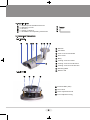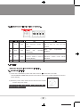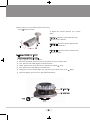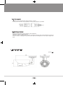
1
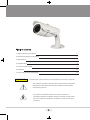
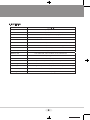
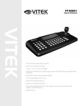
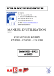
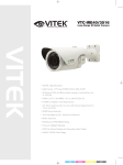
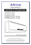
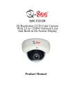
VTC-IRV30/2810
Day/Night IR Bullet Camera w/100’ Range
VITEK
• 1/3” Sony Super HAD II High Resolution Color CCD
• 550 TV Lines of Resolution
• 2.8~10mmm / F1.2 Varifocal Auto Iris Lens
• 30 - 850nm IR LEDs with 100’ Range
• 0 Lux Operation (IR LEDs On)
• IP-66 Rated Water Resistance
• Heavy Duty Mount with Cable Feed Through
• 12VDC/24VAC Dual Voltage Operation
black
Table of contents
1. Safety instructions and Notes
3
2. General Descriptions and Features
4
3. Specifications
5
4. Supplied Items
6
5. Control and Part names
6
6. Installation
7-9
7. Power and Dimensional Drawings
10
WARNING
To prevent fire or shock hazard, do not expose the unit to rain or moisture.
The symbol is intended to alert the user to the presence of important
operating and maintenance(servicing) instructions in the literature
accompanying the unit.
The symbol is intended to alert the user to the presence of
uninsulated "dangerous voltage" within the product's enclosure that
may be of sufficient magnitude to constitute a risk of electric shock
to persons.
2
Caution
To prevent electric shocks
and risk of fire hazards, do
NOT use other than specific
power source.
Warning(NTSC version) -- This equipment has been tested and found to comply with the limits for a Class A
digital device, pursuant to part 15 of the FCC Rules. These limits are designed to provide reasonable
protection against harmful interference when the equipment is operated in a commercial environment. This
equipment generates, uses and can radiate radio frequency energy and if not installed and used in
accordance with the instruction manual, may cause harmful interference to radio communications. Operation
of this equipment in a residential area may cause harmful interference in which case the user will be
required to correct the interference at his/her own expense.
Caution -- Any changes or modifications in construction of this device which are not expressly approved by
the party responsible for compliance could void the user's authority to operate the equipment.
1. Safety instructions, cleaning and Notes
• Please read these safety and operating instructions before placing the camera into operation.
• Keep the manual in a safe place for later reference.
• Pay attention to safety when laying the connection cable and observe that the cable is not
subjected to heavy loads, kinks or damage and that no moisture can penetrate.
• The unit may only be opened by authorized personnel.
• Never open the device and expose boards or lens. If repairs are undertaken by unauthorized
persons the Warranty will be void. If maintenance or repair is required, please call an authorized
service center.
• Use only a mild detergent to clean the housing.
• Keep the window surface clean from the dirt or dust, which may reflect the infrared light into the
lens at night.
3
black
2. General Descriptions and Features
2-1. General Descriptions
This equipment is a weatherproof Day/Night color bullet camera with Sony Super HAD Ⅱ Color
CCD image sensor.
Including 30pcs LED,
- Possible to observe where no illumination is available at night.
- Up to 35Meters (100+’) for outdoor night observation distance.
Aluminum housing,
- Vandal Resistant Camera can be protected from a harsh environment.
Sunshield
- Camera can be protected from overheating in strong sun light.
With Hidden cable-through function
- Cable can be protected from vandalism
- Ease of installation
Dual Voltage 24VAC/12VDC power design,
- Offers flexibility of installation
- Ensures reliability
- Polarity free connection for power is allowed limiting the risk of short
2-2. Features
• 1/3” Super HAD Ⅱ Color
CCD
• Resolution of 550TVL (day-time), 600TVL (night-time)
• Outdoor bullet style camera with Sunshield
• Enhanced sharpness compensation
• 0.05Lux light sensitivity
• Built-in Vari-focal Auto iris lens(2.8~10mm)
• Waterproof (IP66)
• Simple Focus adjustment
• Supply voltage: 24Vac or 12Vdc
• Hidden cable-through function
4
3. Specifications
Description
Image Device
Effective Pixels
1/3” Sony SuperHAD II Color CCD
768 x 494 (NTSC) / 752 x 582 (PAL)
Resolution
550TVL (Day) / 600TVL (Night)
Sensitivity
0.05Lux(F1.2@40IRE), 0Lux with built-in 30 Infrared LEDs
S/N ratio
More than 50dB with AGC off at 50IRE
Electronic Iris
1/60 – 1/100,000sec (NTSC) 1/50 – 1/100,000sec (PAL)
White Balance
3,000°K – 8,000°K Automatic tracking
BLC
Built-in, Factory set to ON
Video Output
VBS 1.0Vpp +/-10%, 75ohm
Built-in Lens
1/3" Vari-Focal, f=2.8-10.0mm, F1.2, DC Auto Iris
Infrared LEDs
IR Distance
Operation Power
Cable length
30pcs @ 850nm
35M (110’)
24Vac(20~28.8Vac) or 12Vdc (11.5~30Vdc), 5Watts max
5’ (1.5M)
Operating Conditions
14 – 122 degrees F (-10°C - +50°C), 85% RH Max. (non-condensing)
Dimensions (Dia. x H)
2.68” x 8.66” (68mm x 220mm)
Net Weight
1.21 lbs (550g)
5
black
4. Supplied Items
①
②
③
④
⑤
1 x Weatherproof D/N Bullet Camera
3 x Mounting screws
3 x anchors
1 x 2.5mm L-Wrench
1 x Installation and Operating Instructions
②
③
④
5. Control and Part names
5-1. External
ⓐ
ⓑ
ⓒⓓ
ⓔ
ⓕ ⓖ ⓗ ⓘ
ⓐ Window
ⓑ Sunshield
ⓒ Lock screw for Sunshield
ⓓ Front cover
ⓔ Body
ⓕ Locking screw for radius
ⓖ Locking screw for Tilt-direction
ⓙ
ⓗ Locking screw for Pan-direction
ⓘ Mounting Base
ⓙ Rubber seal
5-2. Internal
ⓚ
ⓛ
ⓜ
ⓝ
ⓚ Infrared LEDs (X30)
ⓛ Lens Hood
ⓜ Zoom adjustment knob
ⓝ Focus adjustment ring
6
5-3. Iris adjustment and Function switches on the Board.
Iris Low
S/W
Function
Iris High
Default
ON
OFF
ELC mode.
1
ELC
OFF
ALC Mode.
Linear electronic shutter is Set to OFF for auto iris lens
operating.
function.
Back light compensation is
2
BLC
OFF
enabled
and
operating
automatically.
Flickerless mode ON.
3
FL
OFF
4
N/A
OFF
Back
light
compensation
is
disabled.
Flickerless mode OFF.
Electronic shutter is fixed to Electronic shutter mode follows
1/100sec (NTSC).
ELC/ALC.
N/A
N/A
6. Installation
• Make sure the power is removed before installation.
6-1. Procedure of installation
1) Locate at the installation position and drill 3 holes for ⓘMount base on the wall.
Use MOUNTING TEMPLATE printed on the bottom of the inner packing material as shown in
below drawing.
2) Route the power/ video cable from the camera to the monitor
location and power outlet.
Care should be taken not to damage, kink or expose the cable
to a hazardous environment.
7
black
3) Place camera on a pre-drilled position and fix it by
using ②Mounting screws.
4) Adjust the camera direction as in below
steps.
Direction I: Adjust the camera direction with
ⓗscrew for Pan-direction.
Ⅱ
ⓗ
Direction II: Adjust the camera direction with
ⓖ
Ⅲ
Ⅰ
ⓖscrew for Tilt-direction.
ⓕ
Direction III: Adjust the camera direction with
ⓕscrew for radius.
6-2. Setup of ZOOM and FOCUS
• Adjust zoom and focus in order.
1) Open ⓓFront cover for adjustment.
2) Place the separated ⓓFront cover in a safe place away from water & dust.
3) Turn ⓜZoom knob CCW slightly to unlock the knob.
4) Adjust ⓜZoom knob to set the zoom or field of view. (Wide
Tele)
5) Turn ⓜZoom knob CW slightly to lock the knob.
6) Using your thumb and index finger, turn ⓝFocus ring to set the focus. (Far
7) Close and tighten ⓓFront cover. (See CAUTION below)
ⓜ Focus Ring
ⓛ Zoom Knob
3) & 5)
4) & 6)
8
Near)
* IMPORTANT TIP for proper focus adjustment
Step 1. Turn Iris Level adjustment VR clockwise to max position.
Step 2. Set ELC switch to ON at DIP switches.
Step 3. Adjust zoom knob and focus ring of lens.
Step 4. Set ELC switch to OFF at DIP switches.
CAUTION
ⓓFront cover
When assembling ⓓFront cover, be sure
that ⓙRubber sealing is not protrusive.
If ⓓFront cover is tightened excessively,
sealing may not be ensured.
6-3. Sunshield
Camera can be protected from the heat of strong sun light by its Sun shield.
Sunshield must be tightened to the body to avoid detaching by wind.
When the sunshield is properly installed on the
Camera body the ⓒLock screw for Sunshield
should be located in the center of the screw
hole.
The sunshield may be adjusted back or forth
according to the wide or telephoto position of
the lens.
If shades by the sunshield are seen on the
image you may reverse the sunshield direction
backside to front.
9
black
6-4. Power connector
Camera can be operated with either 24VAC or 12VDC.
Polarity free connection is acceptable, but follow the indication if possible.
6-5. Powering sequence
Make sure the power is removed before the installation.
Follow the order for applying power.
Connect the low voltage section (12VDC or 24VAC) first then plug the AC adapter into the AC
outlet to avoid an improper reset from power jitter and damage from the surge voltage after
load.
7. Dimensional Drawings
(Units in mm)
10
11
black
LIMITED LIABILITY WARRANTY
Your new Camera is guaranteed to be free from defects in materials
and workmanship for a period of three years from the date of
purchase.
The product must have been used only for its intended purpose,
and not been subjected to damage by misuse, willful or accidental
damage, caused by excessive voltage or lightning.
The product must not have been tampered with in any way then the
guarantee will be considered null and void.
This guarantee does not affect your statutory rights.
Contact an Authorized VITEK reseller for all servicing needs.
28492 Constellation Road Valencia, ca 91355
WWW.VITEKCCTV.COM