1
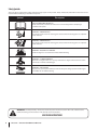
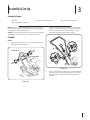
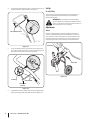
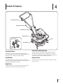
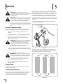
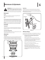
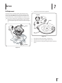
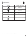
Safe Operation Practices • Set-Up • Operation • Maintenance • Service • Troubleshooting • Warranty Operator’s Manual World Tiller — Series 240 WARNING READ AND FOLLOW ALL SAFETY RULES AND INSTRUCTIONS IN THIS MANUAL BEFORE ATTEMPTING TO OPERATE THIS MACHINE. FAILURE TO COMPLY WITH THESE INSTRUCTIONS MAY RESULT IN PERSONAL INJURY. MTD LLC, P.O. BOX 361131 CLEVELAND, OHIO 44136-0019 Printed In USA Form No. 769-08392 (September 5, 2012) 1 To The Owner Thank You Thank you for purchasing an MTD Garden Tiller. It was carefully engineered to provide excellent performance when properly operated and maintained. If applicable, the power testing information used to establish the power rating of the engine equipped on this machine can be found at www.opei.org or the engine manufacturer’s web site. Please read this entire manual prior to operating the equipment. It instructs you how to safely and easily set up, operate and maintain your machine. Please be sure that you, and any other persons who will operate the machine, carefully follow the recommended safety practices at all times. Failure to do so could result in personal injury or property damage. If you have any problems or questions concerning the machine, phone your local authorized MTD service dealer or contact us directly. MTD’s Customer Support telephone numbers, website address and mailing address can be found on this page. We want to ensure your complete satisfaction at all times. All information in this manual is relative to the most recent product information available at the time of printing. Review this manual frequently to familiarize yourself with the machine, its features and operation. Please be aware that this Operator’s Manual may cover a range of product specifications for various models. Characteristics and features discussed and/or illustrated in this manual may not be applicable to all models. We reserve the right to change product specifications, designs and equipment without notice and without incurring obligation. Throughout this manual, all references to right and left side of the machine are observed from the operating position Table of Contents Safe Operation Practices......................................... 3 Assembly & Set-Up................................................... 7 Controls..................................................................... 9 Operation.................................................................10 Maintenance & Adjustment..................................12 Service......................................................................13 Troubleshooting......................................................14 Replacement Parts..................................................15 Warranty..................................................................16 Record Product Information Model Number Before setting up and operating your new equipment, please locate the model plate on the equipment and record the information in the provided area to the right. You can locate the model plate by standing at the operator’s position and looking down at the rear of the tine shield near the handle. This information will be necessary, should you seek technical support via our web site, Customer Support Department, or with a local authorized service dealer. Serial Number Customer Support Please do NOT return the machine to the retailer or dealer without first contacting the Customer Support Department. If you have difficulty assembling this product or have any questions regarding the controls, operation, or maintenance of this machine, you can seek help from the experts. Choose from the options below: ◊ Visit us on the web at www.mtdproducts..com See How-to Maintenance and Parts Installation Videos at www.mtdparts.com/KnowledgeCenter 2 ◊ Call a Customer Support Representative at 1300 951 594 ◊ Write to MTD Products Australia Pty Ltd. • P.O. Box 376 • Dandenong. Vic. • 3175 2 Important Safe Operation Practices WARNING! This symbol points out important safety instructions which, if not followed, could endanger the personal safety and/or property of yourself and others. Read and follow all instructions in this manual before attempting to operate this machine. Failure to comply with these instructions may result in personal injury. When you see this symbol. HEED ITS WARNING! CALIFORNIA PROPOSITION 65 WARNING! Engine Exhaust, some of its constituents, and certain vehicle components contain or emit chemicals known to State of California to cause cancer and birth defects or other reproductive harm. WARNING! Battery posts, terminals, and related accessories contain lead and lead compounds, chemicals known to the State of California to cause cancer and reproductive harm. Wash hands after handling DANGER! This machine was built to be operated according to the safe operation practices in this manual. As with any type of power equipment, carelessness or error on the part of the operator can result in serious injury. This machine is capable of amputating fingers, hands, toes and feet. Failure to observe the following safety instructions could result in serious injury or death. Training 1. 2. 3. Read, understand, and follow all instructions on the machine and in the manual(s) before attempting to assemble and operate. Keep this manual in a safe place for future and regular reference and for ordering replacement parts. Be familiar with all controls and their proper operation. Know how to stop the machine and disengage them quickly. Never allow children under 14 years of age to operate this machine. Children 14 and over should read and understand the instructions and safe operation practices in this manual and on the machine and be trained and supervised by an adult. 4. Never allow adults to operate this machine without proper instruction. 5. Keep the area of operation clear of all persons, particularly small children and pets. Stop machine if anyone enters the area. Preparation 1. Thoroughly inspect the area where the equipment is to be used. Remove all stones, sticks, wire, and other foreign objects which could be tripped over and cause personal injury. 2. Wear sturdy, rough-soled work shoes and close fitting slacks and shirt. Loose fitting clothes or jewelry can be caught in moving parts. Never operate this machine in bare feet or sandals. 3. Disengage clutch levers and shift (if provided) into neutral (“N”) before starting the engine. 4. Never leave this machine unattended with the engine running. 5. Never attempt to make any adjustments while engine is running, except where specifically recommended in the operator’s manual. Safe Handling of Gasoline: To avoid personal injury or property damage use extreme care in handling gasoline. Gasoline is extremely flammable and the vapors are explosive. Serious personal injury can occur when gasoline is spilled on yourself or your clothes which can ignite. Wash your skin and change clothes immediately. a. Use only an approved gasoline container. b. Never fill containers inside a vehicle or on a truck or trailer bed with a plastic liner. Always place containers on the ground away from your vehicle before filling. 3 c. When practical, remove gas-powered equipment from the truck or trailer and refuel it on the ground. If this is not possible, then refuel such equipment on a trailer with a portable container, rather than from a gasoline dispenser nozzle. d. Keep the nozzle in contact with the rim of the fuel tank or container opening at all times until fueling is complete. Do not use a nozzle lock-open device. e. Extinguish all cigarettes, cigars, pipes and other sources of ignition. f. Never fuel machine indoors. g. Never remove gas cap or add fuel while the engine is hot or running. Allow engine to cool at least two minutes before refueling. h. Never over fill fuel tank. Fill tank to no more than ½ inch below bottom of filler neck to allow space for fuel expansion. i. After striking a foreign object, stop the engine, disconnect the spark plug wire and ground against the engine. Thoroughly inspect the machine for any damage. Repair the damage before starting and operating. 12. Disengage all clutch levers (if fitted) and stop engine before you leave the operating position (behind the handles). Wait until the tines come to a complete stop before unclogging the tines, making any adjustments, or inspections. 13. Never run an engine indoors or in a poorly ventilated area. Engine exhaust contains carbon monoxide, an odorless and deadly gas. 14. Muffler and engine become hot and can cause a burn. Do not touch. 15. Use caution when tilling near fences, buildings and underground utilities. Rotating tines can cause property damage or personal injury. Replace gasoline cap and tighten securely. 16. j. If gasoline is spilled, wipe it off the engine and equipment. Move unit to another area. Wait 5 minutes before starting the engine. Do not overload machine capacity by attempting to till soil too deep at too fast of a rate. 17. k. To reduce fire hazards, keep machine free of grass, leaves, or other debris build-up. Clean up oil or fuel spillage and remove any fuel soaked debris. If the machine should start making an unusual noise or vibration, stop the engine, disconnect the spark plug wire and ground it against the engine. Inspect thoroughly for damage. Repair any damage before starting and operating. l. Never store the machine or fuel container inside where there is an open flame, spark or pilot light as on a water heater, space heater, furnace, clothes dryer or other gas appliances. Operation 4 11. 1. Do not put hands or feet near rotating parts. Contact with the rotating parts can amputate hands and feet. 2. Do not operate machine while under the influence of alcohol or drugs. 3. Never operate this machine without good visibility or light. Always be sure of your footing and keep a firm hold on the handles. 4. 18. Keep all shields, guards, and safety devices in place and operating properly. 19. Never pick up or carry machine while the engine is running. 20. Use only attachments and accessories approved by the manufacturer. Failure to do so can result in personal injury. 21. If situations occur which are not covered in this manual, use care and good judgement. Contact Customer Support for assistance and the name of you nearest servicing dealer.. Maintenance & Storage 1. Keep machine, attachments and accessories in safe working order. 2. Keep bystanders away from the machine while it is in operation. Stop the machine if anyone enters the area. Allow a machine to cool at least five minutes before storing. Never tamper with safety devices. Check their proper operation regularly. 3. 5. Be careful when tilling in hard ground. The tines may catch in the ground and propel the tiller forward. If this occurs, let go of the handle bars and do not restrain the machine. Check bolts and screws for proper tightness at frequent intervals to keep the machine in safe working condition. Also, visually inspect machine for any damage. 4. 6. Exercise extreme caution when operating on or crossing gravel surfaces. Stay alert for hidden hazards or traffic. Do not carry passengers. Before cleaning, repairing, or inspecting, stop the engine and make certain the tines and all moving parts have stopped. Disconnect the spark plug wire and ground it against the engine to prevent unintended starting. 7. Never operate the machine at high transport speeds on hard or slippery surfaces. 5. 8. Exercise caution to avoid slipping or falling. Do not change the engine governor settings or over-speed the engine. The governor controls the maximum safe operating speed of engine. 9. Look down and behind and use care when in reverse or pulling machine towards you. 6. Maintain or replace safety and instruction labels, as necessary. 10. Start the engine according to the instructions found in this manual and keep feet well away from the tines at all times. 7. Follow this manual for safe loading, unloading, transporting, and storage of this machine. 8. Always refer to the operator’s manual for important details if the machine is to be stored for an extended period. Section 2 — Important Safe Operation Practices 9. If the fuel tank has to be drained, do this outdoors. 10. Observe proper disposal laws and regulations for gas, oil, etc. to protect the environment. 11. According to the Consumer Products Safety Commission (CPSC) and the U.S. Environmental Protection Agency (EPA), this product has an Average Useful Life of seven (7) years, or 130 hours of operation. At the end of the Average Useful Life have the machine inspected annually by an authorized service dealer to ensure that all mechanical and safety systems are working properly and not worn excessively. Failure to do so can result in accidents, injuries or death. Notice Regarding Emissions Engines which are certified to comply with California and federal EPA emission regulations for SORE (Small Off Road Equipment) are certified to operate on regular unleaded gasoline, and may include the following emission control systems: Engine Modification (EM), Oxidizing Catalyst (OC), Secondary Air Injection (SAI) and Three Way Catalyst (TWC) if so equipped. Spark Arrestor WARNING! This machine is equipped with an internal combustion engine and should not be used on or near any unimproved forest-covered, brushcovered or grass-covered land unless the engine’s exhaust system is equipped with a spark arrestor meeting applicable local or state laws (if any). If a spark arrestor is used, it should be maintained in effective working order by the operator. In the State of California the above is required by law (Section 4442 of the California Public Resources Code). Other states may have similar laws. Federal laws apply on federal lands. A spark arrestor for the muffler is available through your nearest engine authorized service dealer or contact the service department, P.O. Box 361131 Cleveland, Ohio 44136-0019. Section 2 — Important Safe Operation Practices 5 Safety Symbols This page depicts and describes safety symbols that may appear on this product. Read, understand, and follow all instructions on the machine before attempting to assemble and operate. Symbol Description READ THE OPERATOR’S MANUAL(S) Read, understand, and follow all instructions in the manual(s) before attempting to assemble and operate WARNING— ROTATING TINES Do not put hands or feet near rotating parts. Contact with the rotating parts can amputate hands and feet. WARNING— ROTATING TINES Do not put hands or feet near rotating parts. Contact with the rotating parts can amputate hands and feet. WARNING—GASOLINE IS FLAMMABLE Allow the engine to cool at least two minutes before refueling. WARNING— CARBON MONOXIDE Never run an engine indoors or in a poorly ventilated area. Engine exhaust contains carbon monoxide, an odorless and deadly gas. WARNING— HOT SURFACE Engine parts, especially the muffler, become extremely hot during operation. Allow engine and muffler to cool before touching. WARNING! Your Responsibility—Restrict the use of this power machine to persons who read, understand and follow the warnings and instructions in this manual and on the machine. SAVE THESE INSTRUCTIONS! 6 Section 2 — Important Safe Operation Practices 3 Assembly & Set-Up Contents of Carton • One Tiller • • One Engine Operator’s Manual One 20 oz. bottle SAE 30W oil NOTE: The tiller is shipped without gasoline or oil in the engine. Fill up gasoline and oil as instructed in the accompanying engine manual before operating your machine. 2. NOTE: This operator’s manual may cover various models of tillers. The machines illustrated may vary slightly from your tiller. • One Tiller Operator’s Manual Position the upper handle onto the lower handle, Step A in Figure 4-2. Align the holes on the lower handle with the holes on the upper handle. Choose the upper or lower holes depending on the desired handle height. Assembly Handle 1. Remove the star handle knobs and the carriage bolts from the lower handle. See Figure 4-1. A B Handle Knobs Carriage Bolts B Figure 4-2 3. Insert carriage bolts through the holes and secure with the star knobs, Step B in Figure 4-2. Make certain the carriage bolts are seated securely into one of the two positions provided. Figure 4-1 7 4. Insert the left end of the tine clutch control into the hole on the left side of the upper handle. See Figure 4-3. Set-Up Gas & Oil Fill-Up Service the engine with gasoline and oil as instructed in the separate engine manual packed with your tiller. Read the instructions carefully. WARNING! Use extreme care when handling gasoline. Gasoline is extremely flammable and the vapors are explosive. Never fuel machine indoors or while the engine is hot or running. Adjustments Wheels Tine Clutch Control The tiller is shipped with the wheels adjusted such that the unit sits level. Before tilling, the wheels must be raised. To do this, remove the clevis and cotter pins, raise the wheels to the desired position, then reattach pins to secure, Figure 4-5. For transporting the tiller, reverse the steps to lower the wheels. Figure 4-3 5. Cotter Pin Insert the Z-fitting on the clutch cable into the hole on the tine clutch control. Hook the “Z” end into the opening from the inside to the outside as shown in Figure 4-4. Clevis Pin Figure 4-5 Z-fitting Clutch Cable Tine Clutch Control Figure 4-4 6. 8 Squeeze the tine clutch control inward. Insert the right end into the hole on the right side of the upper handle. See Figure 4-3. Section 3— Assembly & Set-Up 4 Controls & Features Tine Clutch Control Clutch Cable Handle Knobs Depth Stake Tines Back of Tiller Rear Wheels Rear Wheels Depth Stake Tine Clutch Control Rear Wheels with Depth Stake The clutch control lever is located on the upper handle. Squeezing the lever against the handle engages the tine drive. Release the lever to stop the tines from turning. The rear wheels can be raised and lowered for transport and storage. Refer to the Maintenance & Adjustments Section for instructions on depth stake adjustment and the Assembly & SetUp Section for instructions on wheel adjustment. Handle Knobs Engine Controls The handle height may be adjusted. Loosen the knobs and remove the carriage bolts to change the position. Reinstall and tighten the hardware when complete. Refer to the engine manual for information and function of the engine controls. Depth Stake The depth stake acts as a brake for the tiller and controls the depth and speed at which the machine will operate. 9 5 Operation WARNING! Read, understand, and follow all instructions and warnings posted on the machine, in this manual and in the separate engine manual before operating. WARNING! Be sure no one other than the operator is standing near the tiller while starting the engine or operating the unit. Never run the engine indoors or in enclosed, poorly ventilated areas. Engine exhaust contains carbon monoxide, an odorless and deadly gas. Keep hands, feet, hair and loose clothing away from any moving parts on the engine and the tiller. The working depth of the machine may be predetermined by setting the depth stake so that the wheels are about four inches from the ground when the tines and depth stake are resting on the ground. This setting will permit a working depth of about four inches. When presetting the working depth, the handles should be adjusted so the hand grips are a little above the waist. The tiller will be lower when the tines and depth stake penetrate the ground. For tilling, the depth stake must be lowered and the wheels must be raised. See Figure 6-1. Starting & Stopping the Engine With the spark plug wire disconnected from the spark plug, perform the following checks and services before each use: 1. Check unit for loose or missing hardware. Service as required. 2. Check engine oil level. See the Engine Operator’s Manual. 3. Check that all safety guards and covers are in place. 4. Check air cleaner and engine cooling system. See the Engine Operator’s Manual. WARNING! GASOLINE IS HIGHLY FLAMMABLE AND ITS VAPORS ARE EXPLOSIVE. Follow the gasoline safety rules in the Important Safe Operations Practices section of this manual. Failure to follow gasoline safety instructions can result in serious personal injury and property damage. 5. 6. Fill the fuel tank with gasoline according to the directions in the Engine Operator’s Manual. Follow all instructions and safety rules carefully. Attach the spark plug wire to the spark plug. Figure 6-1 When tilling, leave approximately eight inches of untilled soil between the first and second tilling paths, then make the third path between the first and second. See Figure 6-2. WARNING! Never run the engine indoors or in an enclosed, poorly ventilated area. Engine exhaust contains carbon monoxide, an odorless and deadly gas. Avoid the engine muffler and nearby areas. Temperatures in these areas may exceed 150° F. 7. Release all of the controls on the tiller. 8. Start and stop the engine as instructed in the Engine Operator’s Manual Using Your Tiller 4 5 2 Your tiller is designed for seed bed preparation, cultivating, furrowing, and mulching. Controlling Tilling and Depth Speed By increasing the depth of the depth stake, the forward speed of the machine is reduced and the working depth is increased. When the depth stake is raised, the working depth of the machine is reduced and the forward speed is increased. Figure 6-2 10 3 1 In some soils, the desired depth is obtained the first time over the garden. In other soils, the desired depth is obtained by going over the garden two or three times. Passes should be made across the length and width of the garden alternately. Rocks which are turned up should be removed from the garden area. substantially increase the fertility of your garden. Handle Pressure Transporting and Storing the Tiller Further control of tilling depth and travel speed can be obtained by variation of pressure on the handles. A downward pressure on the handles will reduce the working depth and increase the forward speed. An upward pressure on the handles will increase the working depth and reduce the forward speed. The type of soil and working conditions will determine the actual setting of the depth stake and the handle pressure required. For proper decaying action, fertilizer should be applied and worked in with the mulch materials. Breaking up leaves and straw and mixing it with several inches of soil allows proper aeration of the plant root system and retards the growth of weeds. To transport the tiller, lower the wheels and move the depth stake to the highest position. See Figure 6-4. Cultivating For cultivating, a two to three inch depth is desirable. With the outer tines installed (Series 240), the working width of the machine is 22 or 24 inches. The working width of Series 220 machines is fixed at 16 inches For cultivation, the tine width can be reduced to 13 inches (Series 240), by removing the outer tines, refer to the Adjustment Section. When laying out plant rows, be sure to allow enough width to permit cultivation between the rows. In growing corn or similar crops, check-row planting will permit cross cultivation and practically eliminate hand hoeing, Figure 6-3. Figure 6-4 To store the tiller, lower the wheels and orient the depth stake so both are touching the ground. See Figure 6-5. Figure 6-3 The tiller has many uses other than tilling and cultivating a garden. One of these is the preparation of lawn area for seeding. The tiller will prepare a deep seed bed which will be free of hard untilled spots, allowing a better stand of grass to grow. The tiller is very useful for loosening hard soil for excavation with a shovel; No tedious handwork will be necessary. Your tiller may be used for mixing compost in the pile or for mixing it with the soil in your garden. This should be done after the soil has been broken to the full working depth. The compost should be worked in to a depth of six to seven inches. This may be done by working the length of the garden and then by making separate passes across its width. The addition of decayed organic matter will Figure 6-5 Section 5 — Operation 11 6 Maintenance & Adjustments WARNING! Before inspecting, cleaning or servicing the tiller, shut off the engine and wait for all moving parts to come to a complete stop. Disconnect the spark plug. Failure to follow these instructions properly can result in serious personal injury or property damage. Maintenance Depth Stake The depth stake acts as a brake for the tiller and controls the depth and speed at which the machine will operate, Figure 7-2. Remove the clevis and cotter pins, raise or lower the depth stake, then reattach pins to secure. Engine Refer to the Engine Operator’s Manual packaged with your machine for all engine maintenance. Cotter Pin Tines Clean the underside of the tine shield after each use. The dirt washes off the tines easier if rinsed off immediately instead of after it dries. Always towel dry the tiller afterwards and apply a light coat of oil or silicone to prevent rusting or water damage. NOTE: Never use a pressure washer to clean the tiller. Water can penetrate tight areas of the tiller and cause serious damage. Clevis Pin Lubrication Transmission The transmission is pre-lubricated and sealed at the factory. It requires no maintenance. See an authorized service dealer for any service issues. Figure 7-2 Tine Shaft and Wheel Shaft Remove tine assemblies and wheel and lubricate the tine shaft and wheel shaft at least once a season. Adjustments Tine Width The tilling width 22” but can increase to 24 inches by removing the clevis and cotter pins, sliding each outer tine out 1”, and securing in this position with the pins. Reduce the tine width to 13 inches by removing the outer tines completely. See Figure 7-2. Cotter Pin Clevis Pin 24-inch 22-inch 13-inch 12 Figure 7-1 Off-Season Storage If the tiller will not be used for a period longer than 30 days, the following steps should be taken to prepare the tiller for storage. • Clean the exterior of the engine and the entire tiller thoroughly. Lubricate the tiller as described in the Lubrication instructions. • The use of pressure washers to clean your tiller is not recommended. It may cause damage to pulleys, bearings, or the engine. The use of pressure washers will result in shortened life and reduce serviceability. • Refer to the engine manual for engine storage instructions. • Wipe tines with oiled rag to prevent rust. • Store tiller in a clean, dry area. Do not store next to corrosive materials, such as fertilizer. • When storing any type of power equipment in an unventilated or metal storage shed, care should be taken to rustproof the equipment. Using a light oil or silicone, coat the equipment and especially any springs, bearings, and cables. 7 Service Belt Replacement 2. Loosen the lock nut shown in Figure 8-2. Your tiller has been engineered with a belt made of special material for longer life and better performance. Replace with a factory-approved OEM belt. See the retailer from which you purchased your tiller, an authorized MTD Service Dealer, or call 1-800-800-7310 for information regarding price and availability. 1. Lock Nut Remove the engine by removing the six screws and lock nuts holding the engine and cover to the shield. See Figure 8-1. Pulley Screw Belt Figure 8-2 3. Unloop the belt from the pulleys. See Figure 8-2. 4. Reassemble the new belt and tighten the lock nut. 5. Reattach belt cover and engine using the hardware removed earlier. Lock Nut Figure 8-1 13 8 Troubleshooting Problem Tines do not engage 14 Cause Remedy 1. Foreign object lodged in tines 1. Stop tiller completely, check and discard foreign object 2. Tine clevis pin(s) missing 2. Replace tine clevis pin(s) 3. Belt worn and/or stretched 3. Replace belt 4. Pulley and idler not in correct adjustment 4. Take unit to authorized service 9 Replacement Parts Component Part Number and Description 642-0002 642-0003 Inner Right Hand Tine Inner Left Hand Tine 642-0005 642-0004 Outer Left Hand Tine Outer Right Hand Tine 714-04043 911-0415 Bow-tie Pin Clevis Pin 946-04626 Clutch Cable 734-0973 Wheel, 5.0 x 1.38 Phone (800) 800-7310 to order replacement parts or a complete Parts Manual (have your full model number and serial number ready). Parts Manual downloads are also available free of charge at www.mtdproducts.com. 15 Warranty Conditions — Australia (Not applicable to other Regions) The benefits given to you under this warranty are in addition to other rights and remedies that you have under Australian law in relation to the goods. MTD Products Australia Pty Ltd warrants that this machine is free from defects in material and workmanship. This warranty is limited to repairing or replacing any part which appears upon inspection by MTD Products Australia Pty Ltd or its agent to be defective in material or workmanship. A separate warranty is provided in respect of the engine for this machine. Refer to the engine warranty statement in the Engine Owner’s Manual which has been included with this machine. For domestic use, this warranty will apply for a period of 2 years from date of purchase. Warranty for commercial or industrial use is 90days from the date of purchase. In the event of dispute, MTD Products Australia Pty Ltd will determine whether the machine was used for domestic, or commercial or industrial use. All costs associated with claiming under this warranty must be borne by you, including transport costs incurred in the repair or replacement of any defective part. This warranty excludes fair wear and tear and any damage caused by misuse or abuse. Parts such as Blades, Bump Knobs, Outer Spools, Cutting Line, Inner Reels, Starter Pulley, Starter Ropes, Drive Belts, Saw Blades, Guide Bars, Cultivator Tines, Spark Plugs, Carburettor Adjustments and Filters which can be subjected to use beyond their normal intended working capacity are also excluded. This warranty is void if alterations are made to the machine without MTD Products Australia Pty Ltd prior written authority. Our goods come with guarantees that cannot be excluded under the Australian Consumer Law. You are entitled to a replacement or refund for a major failure and for compensation for any other reasonably foreseeable loss or damage. You are also entitled to have the goods repaired or replaced if the goods fail to be of acceptable quality and the failure does not amount to a major failure. IN ORDER TO MAKE A CLAIM UNDER THIS WARRANTY YOU WILL NEED TO TAKE YOUR PRODUCT AND YOUR PROOF OF PURCHASE TO AN AUTHORISED MTD DEALER. YOUR NEAREST MTD DEALER CAN BE FOUND at www. mtd.com.au. All SERVICING AND REPAIRS MUST USE GENUINE SPARE PARTS OR YOUR WARRANTY WILL BE VOID. For your Record: Retailers Name:.........................................................................Address: ....................................................................................... Phone No: ................................................................................... Model No: ................................................................................... Serial No: ..................................................................................... Date of Purchase: ..................................................................... MTD Products Australia Pty Ltd. Postal Address: PO. Box 376 Dandenong. Vic. 3175 Business Address: 6 Zenith Road, Dandenong. Vic. 3175 and 97 Trade Street. Lytton. Qld. 4178 Email Address: [email protected] A.B.N. 96 004 873 572 Customer Service Phone: 1300 951 594 © Copyright 2012 04016921 Revision 10.1. 2012