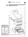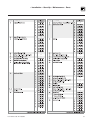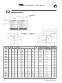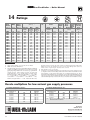
1
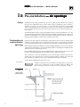
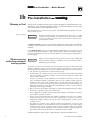
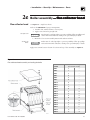
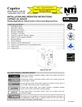
LGB Gas–Fired Boiler Boiler Manual • Installation • Maintenance • Start-up • Parts Refer to Control Supplement for additional information Read all instructions before installing Installer Owner Leave all instructions with boiler for future reference. Any claims for damage or shortage in shipment must be filed immediately against the transportation company by the consignee. Installation and service should be performed by qualified contractor. Part No. 550-141-186/0703 LGB Gas-Fired Boiler — Boiler Manual Read this page first Hazard definitions The following defined terms are used throughout this manual to bring attention to the presence of hazards of various risk levels, or to important information concerning the life of the product. Indicates presence of hazards that will cause severe personal injury, death or substantial property damage. Indicates presence of hazards that can cause severe personal injury, death or substantial property damage. Indicates presence of hazards that will or can cause minor personal injury or property damage. Indicates special instructions on installation, operation or maintenance that are important but not related to personal injury or property damage. The boiler contains ceramic fiber and fiberglass materials. Use care when handling these materials per instructions on page 28 of this manual. Failure to comply could result in severe personal injury. When calling or writing about the boiler— Please have the boiler model number from the boiler rating label and the CP number from the boiler jacket. You may list the CP number in the space provided on the Installation and service certificate found on page 27. Read all instructions before installing. Failure to follow all instructions in proper order can cause severe personal injury, death or substantial property damage. Do not use petroleum-based cleaning or sealing compounds in boiler system. Severe damage to system components can result, causing substantial property damage. 2 Part Number 550-141-186/0703 • Installation • Start-Up • Maintenance • Parts Contents 1 2 3 4 5 6 7 8 9 10 11 12 13 14 Part Number 550-141-186/0703 Pre-installation Codes .......................................................................................... 4 Air openings ............................................................................... 4 Venting ........................................................................................ 6 Foundation .................................................................................. 8 Boiler assembly Base.............................................................................................9 Sections ....................................................................................10 Hydrostatic pressure test .........................................................12 Cleanout plates .........................................................................14 Flue collector hood...................................................................15 Piping Water boilers ............................................................................16 Steam boilers ............................................................................18 Multiple steam boilers ..............................................................20 Jacket ...............................................................................................21 Draft hood ........................................................................................21 Install boiler controls .....................................................................22 Final adjustment Water boilers ............................................................................24 Steam boilers ............................................................................25 Placing boiler in operation ............................................................26 Check-out procedure ......................................................................27 Maintenance ....................................................................................28 Replacement parts ..........................................................................32 Dimensions ......................................................................................34 Equipment — standard and optional ...........................................35 Ratings .............................................................................................36 Gas piping ............................................... (See Control Supplement) Wiring ...................................................... (See Control Supplement) 3 LGB Gas-Fired Boiler — Boiler Manual 1a Codes Pre-installation — air openings Installations must comply with all local codes, laws, regulations and ordinances, also National Fuel Gas Code ANSI Z223.1–latest edition. When required, installations must conform to Standard for Controls and Safety Devices for Automatically Fired Boilers, ANSI/ASME CSD-1. Safe lighting and other performance criteria were met with the gas manifold and control assembly provided on boiler when boiler underwent tests specified in ANSI Z21.13– latest edition. Canadian installations must comply with CAN/CSA B149.1 or B149.2 Installation Code. The equipment shall be installed in accordance with those installation regulations in force in the local area where the installation is to be made. These shall be carefully followed in all cases. Authorities having jurisdiction shall be consulted before installations are made. Combustion air and ventilation openings Combustion air and ventilation openings must comply with Section 5.3, Air for Combustion and Ventilation, of National Fuel Gas Code ANSI Z233.1–latest edition, or applicable local building codes. Canadian installations must comply with CAN/CSA B149.1 or B149.2 Installation Code. Boiler installation must assure sufficient openings in building and boiler room to provide adequate combustion air and ventilation. Consider construction tightness of building when deciding whether additional outside openings may be needed. Older buildings with single-pane window, minimal weather-stripping and no vapor barrier often provide enough natural infiltration and ventilation without dedicated openings. New construction or remodeled buildings are most often built tighter. Windows and doors are weather-stripped, vapor barriers are used and openings in walls are caulked. As a result, such tight construction is unlikely to allow proper natural air infiltration and ventilation. Air from inside building (boiler in interior room): Air openings Adequate combustion air and ventilation openings must be provided to assure proper combustion, prevent possibility of flue gas spillage and carbon monoxide emissions, causing severe personal injury or death. Figure 1 Boiler room below grade 4 Part Number 550-141-186/0703 • Installation • Start-Up • Maintenance • Parts Combustion air and ventilation openings (continued) • • Tightly constructed buildings must be provided with openings to outside for combustion and ventilation air. These openings must be sized to handle all fuel-burning appliances, exhaust and ventilation fans and fireplaces. When openings to boiler room are taken to interior spaces, provide two permanent openings: a combustion air opening within 12 inches of floor and a ventilation opening within 12 inches of ceiling. Each opening must provide a minimum free area of one square inch per 1,000 Btuh input of all appliances in room plus requirements for any exhaust fans in room. The interior space supplying combustion and ventilation air must have adequate infiltration from outside. Air directly from outside to boiler room: • Tightly constructed buildings must be provided with combustion air and ventilation openings to boiler room which are adequate to handle the boiler needs plus the needs of all other fuel-burning appliances, fireplaces and exhaust or ventilation fans. • Combustion and ventilation openings connecting directly or by ducting to outside, or to attic or crawl spaces that freely connect with outside, must be sized as follows: 1. Outside wall or vertical ducting — one square inch per 4.000 Btuh input of all appliances in room plus requirements for any exhaust fans or other appliances in room. 2. Horizontal ducting — one square inch per 2,000 Btuh of all appliances in room plus requirements for any exhaust fans or other appliances in room. 3. All ducting must be same size as permanent openings. Minimum area dimensions of ducting must be no less than 9 square inches. 4. Other size ducting must comply with local codes. Compensate for louver blockage when calculating combustion air and ventilation openings. See Figures 1 and 2. Refer to manufacturer's instructions for sizing. Adjustable louvers must be locked open and combustion air damper must interlock with boiler controls to open automatically before boiler operation. Figure 2 Boiler room partially or completely above grade Part Number 550-141-186/0703 5 LGB Gas-Fired Boiler — Boiler Manual 1b Chimney or Vent Pre-installation — venting Venting must be installed according to Part 7, Venting of Equipment, of National Fuel Gas Code, ANSI Z223.1–latest edition and applicable building codes. Canadian installations must comply with CAN/CSA B149.1 or B149.2 Installation Code. Breeching must not be connected to any portion of mechanical draft system that can operate under positive pressure. Flue gas spillage Long horizontal breechings, excessive numbers of elbows or tees, or other obstructions restricting flow of combustion gases can result in possibility of flue gas spillage and carbon monoxide emissions, causing severe personal injury or death. See Figures 3, 4 and 5 on page 7 for typical venting configurations. Ensure that your installation complies with the requirements given in these illustrations and with all local codes and standards. See the Ratings table on page 36, for minimum breeching diameter. Use heavy gauge steel breeching (Type B vent material or single wall metal pipe). Where horizontal breeching is used, slope upward at least ¼" per foot toward chimney or vent and support with hangers to prevent sagging. When removing boiler from common venting system Failure to follow all instructions listed below can cause flue spillage and carbon monoxide emissions, resulting in severe personal injury, death or substantial property damage. At the time of removal of an existing boiler, the following steps shall be followed with each appliance remaining connected to the common venting system placed in operation, while the other appliances remaining connected to the common venting system are not in operation. a. Seal any unused openings in the common venting system. b. Visually inspect the venting system for proper size and horizontal pitch and determine there is no blockage or restriction, leakage, corrosion and other deficiencies which could cause an unsafe condition. c. Insofar as is practical, close all building doors and windows and all doors between the space in which the appliances remaining connected to the common venting system are located and other spaces of the building. Turn on clothes dryers and any appliance not connected to the common venting system. Turn on any exhaust fans, such as range hoods and bathroom exhausts, so they will operate at maximum speed. Do not operate a summer exhaust fan. Close fireplace dampers. d. Place in operation the appliance being inspected. Follow the lighting instructions. Adjust thermostat so appliance will operate continuously. e. Test for spillage at the draft hood relief opening after 5 minutes of main burner operation. Use the flame of a match or candle. f. After it has been determined that each appliance remaining connected to the common venting system properly vents when tested as outlined above, return doors, windows, exhaust fans, fireplace dampers, and any other gas-burning appliance to their previous conditions of use. g. Any improper operation of the common venting system should be corrected so the installation conforms to the National Fuel Gas Code, ANSI Z223.1–latest edition. When resizing any portion of the common venting system, the common venting system should be resized to approach the minimum size as determined using the appropriate tables in Appendix G in the National Fuel Gas Code ANSI Z223.1–latest edition. Canadian installations must comply to CAN/CSA B149.1 or B149.2 Installation Codes. 6 Part Number 550-141-186/0703 • Installation • Start-Up • Maintenance • Parts Figure 3 Figure 4 Individual stub vents Combined vents Figure 5 Offset vents Notes Part Number 550-141-186/0703 1 Minimum vent height using full size connector. 2 Minimum 2 feet above any structure within 10 feet. 3 Vent and combined vent materials, length and diameter must be determined using the combined venting tables of the National Fuel Gas Code, ANSI Z223.1–latest edition, or other accepted engineering design method. Use a connector rise as high as possible to improve vent connector capacity. 4 Vent and vent connector material and design must be determined using the individual venting tables of the National Fuel Gas Code, ANSI Z223.1–latest edition, or other accepted engineering design method. Use a connector rise as high as possible to improve vent connector capacity. 7 LGB Gas-Fired Boiler — Boiler Manual 1c Select the boiler location Flammable materials Installation clearances Pre-installation — foundation Consider all connections to the boiler before selecting a location. Boiler must be installed so gas control system components are protected from dripping or spraying water or rain during operation or service. To avoid personal injury, death or property damage, keep the boiler area clear and free from combustible materials, gasoline and other flammable vapors and liquids. Suggested minimum clearances for servicing: • 24 inches for access to controls and components front and sides. • 6 inches from draft hood to wall, for cleaning flueways. Required clearances in confined spaces: • Vent pipe must be at least 6 inches from combustible material. • Minimum 24" between jacket and combustible walls and ceiling. For LGB-6 through LGB-23 IRI and LGB-21 through LGB-23 FM/CSD-1, the gas train is located outside the boiler. Provide additional clearance. Install in a space large in comparison to size of boiler. Boiler foundation Fire hazard. Never install boiler on combustible flooring or carpeting, even if a concrete or aerated foundation is used. Severe personal injury, death or substantial property damage can result. Do not route wiring, telephone cables or piping in the floor below the boiler. Overheating could occur, resulting in severe personal injury, death or substantial property damage. Level concrete or brick foundation, minimum 2" thick, (Figure 6) is required if: • There is a possibility of the floor becoming flooded. • Non-level conditions exist. Use foundation with airways when concrete floor is “green”. Figure 6 Foundation 8 Boiler Model Number “W” Inches Boiler Model Number “W” Inches LGB-4 21 LGB-14 71 LGB-5 26 LGB-15 76 LGB-6 31 LGB-16 81 LGB-7 36 LGB-17 86 LGB-8 41 LGB-18 91 LGB-9 46 LGB-19 96 LGB-10 51 LGB-20 101 LGB-11 56 LGB-21 106 LGB-12 61 LGB-22 111 LGB-13 66 LGB-23 116 Part Number 550-141-186/0703 • Installation • Start-Up • Maintenance • Parts 2a Base assembly Boiler assembly — base The boiler contains ceramic fiber and fiberglass materials. Use care when handling these materials per instructions on page 28 of this manual. Failure to comply could result in severe personal injury. Check for proper orifice size: • Natural gas – 3.95 mm • Propane gas – 2.40 mm Proper orifices must be used. Failure to do so will cause severe personal injury, death or substantial property damage. Orifices Assembly order Before assembling base, relocate access shield from lower shipping holes to upper mounting holes. See Figure 7. • Base sizes 4, 5, A, B and C — one mounting hole. • Base sizes D, E, F and G — two mounting holes. Base assembly must be located in order shown in Base ArrangementTable, below, so flue collector/ draft hoods, jackets, and gas controls are installed in correct position. Assemble base(s) as shown in Figure 8, in the order shown in the table below. Dual base shown. Level and straighten burners to avoid misfiring. Burner seating Burners must be properly seated in their locating slots with openings facing up. Front of burners must rest fully over main burner orifices. Gas orifices must inject down center of burners. Failure to properly level and seat burners will result in severe personal injury, death or substantial property damage. Base Arrangement Table (Note 1) Figure 7 Access shield (sizes D, E, F and G shown) Boiler Model Number Base Size Boiler Model Number Base Size LGB-4 4 -- LGB-14 C B LGB-5 5 -- LGB-15 C C LGB-6 A -- LGB-16 D C LGB-7 B -- LGB-17 D D LGB-8 C -- LGB-18 E D LGB-9 D -- LGB-19 E E LGB-10 E -- LGB-20 F E LGB-11 F -- LGB-21 F F LGB-12 G -- LGB-22 G F LGB-13 B B LGB-23 G G Note 1: From boiler left side (front view). Side panels shipped in separate carton. Figure 8 Base assembly Part Number 550-141-186/0703 9 LGB Gas-Fired Boiler — Boiler Manual 2b Section assembly Boiler assembly — sections Assembly may start at either end section. For easier assembly start with right end section. 1. Position right end section flush with right end of base. See Figure 13 on page 15. Sections are top-heavy Sections are top heavy and will not stand individually without support. Severe personal injury, death or substantial property damage can result. 2. With caulking gun, apply 1/8" continuous bead of sealing rope adhesive in sealing grooves. See Figure 9. 3. Place ½" rope in groove. Around curves, grasp at 1" intervals and push together. Do not stretch. Cut rope as each section is completed. See Figure 9. Do not precut rope Do not precut rope. Gas tight seal must be maintained to prevent possibility of flue gas spillage and carbon monoxide emissions, causing personal injury or death. 4. Remove any grit from port opening sealing surfaces with clean rag. Note Warning below. No petroleumbased chemicals Do not use any cleaner containing petroleum-based distillate (oil). Elastomer seal failure will occur, causing substantial property damage. Clean port sealing surfaces Remove all grit or rust from port opening sealing surfaces. Failure to do so may cause a seal failure, resulting in severe personal injury, death or substantial property damage. 5. Place sealing rings in port openings. See Figure 9. 6. Prepare intermediate section: a. Remove grit or rust from port opening sealing surfaces. Note Warning above. b. Position intermediate sections so alignment lugs fit into sockets of next section. Refer to Figure 10, page 11. Figure 9 Sealing rope and seals 10 Part Number 550-141-186/0703 • Installation • Start-Up • Maintenance • Parts Section assembly 7. Discard 3/8" diameter shipping tie rods. Do not use to draw sections together. (continued) 8. Draw sections together until metal-to-metal contact is made around machined port opening. See Figure 10. a. Oil threads on three draw rods. Install washer and nut on end to be tightened. Use nut only on other end. b. Uniformly draw sections together, starting at washer/nut end. c. Draw rods should be torqued to a range of 100-120 ft/lbs. Do not back off draw rods. d. Metal-to-metal contact will be achieved around port opening. See Figure 10. If a gap does exist, it should be no greater than .032". Check with feeler gauge. Verify metal to metal contact at ports If for any reason gap around port opening exceeds .032", check for rope extending from rope grooves, dirt on port openings or sockets, or misaligned lugs. If corrections are made and gap still exists, contact your Weil-McLain distributor or sales office before continuing installation. Failure to correct this situation could cause seal failure, resulting in severe personal injury, death or substantial property damage. End section must be plumb End section must be plumb. After erecting 1st intermediate section, check both sections for plumb. Failure to plumb sections may cause misaligned piping and breeching, resulting in minor property damage. 9. Follow steps 2 through 8 for remaining intermediates and left end section. Check sealing rope Check sealing rope of each section before proceeding to next section. Boiler must be sealed gas-tight to prevent possibility of flue gas spillage and carbon monoxide emissions, causing severe personal injury or death. Figure 10 Sealing ring installation and port alignment Part Number 550-141-186/0703 11 LGB Gas-Fired Boiler — Boiler Manual 2c Boiler assembly — pressure test Hydrostatic pressure test Pressure test before connecting gas piping and electrical supply. 1. Refer to Figures 11a and 11b for control tapping locations. Install: a. Boiler drain (not supplied). b. Water pressure gauge — for test only. Be sure gauge can handle test pressures. See Step 3. 2. Plug remaining tappings. No controls installed DO NOT pressure test with any controls installed. Damage to control can occur. 3. Fill boiler. Vent all air. For more than 10 minutes, pressure-test: a. Steam boilers between 45 - 55 psig. b. Water boilers 1 ½ times maximum working pressure stated on castings and boiler nameplate. Do not leave boiler unattended Do not leave boiler unattended. Cold water fill could expand and cause excess pressure, resulting in severe personal injury, death or substantial property damage. Figure 11a Tapping Size Steam Boilers Inches C1 D1 & D2 Water Boilers 11/4 Boiler drain Boiler drain / Gauge glass -- 12 Left end section tappings (note 4) (note 3) E1 & E2 1 Low water cutoff (note 3) E1 1 Optional low water cutoff Pressure operating & limit controls and pressure gauge Limit control To expansion tank or automatic air vent (note 2) F1 1 -- G1 34 / -- H1 & H2 38 / Tri-cock -- J1 2 Steam relief valve & skim tapping Water relief valve & skim tapping K1 12 / -- Combination pressure & temperature gauge M1 & M2 1 Optional low water Optional low water cutoff (note 3) cutoff M1 1 Firing rate control (note 2) Operating control (note 2) (note 1) (note 2) (when used) Firing rate control (when used) or Probe low water cutoff Notes: 1. Available on special request only. 2. Must be on same side as supply to system. 3. Must be on same side as steam equalizer piping. 4. Additional controls for water boilers may be placed in supply piping. 12 Part Number 550-141-186/0703 • Installation • Start-Up • Maintenance • Parts Hydrostatic pressure test 4. Check for maintained gauge pressure and leaks. Repair if found. 5. Drain boiler and remove plugs from tappings used for controls and accessories. (continued) Repair leaks at once Leaks must be repaired at once. Failure to do so can damage boiler, resulting in substantial property damage. No petroleumbased chemicals Do not use petroleum-based cleaning or sealing compounds in boiler system. Severe damage to boiler will result, causing substantial property damage. Figure 11b Right end section tappings Tapping Size Steam Boilers Inches C2 D3 & D4 Water Boilers (note 4) 11/4 Boiler drain Boiler drain / Gauge glass -- 12 (note 3) E3 & E4 1 Low water cutoff (note 3) E3 1 Optional low water cutoff Pressure operating & limit controls and pressure gauge Limit control To expansion tank or automatic air vent (note 2) F2 1 -- G2 34 / -- H3 & H4 38 / Tri-cock -- J2 2 Steam relief valve & skim tapping Water relief valve & skim tapping K2 12 / -- Combination pressure & temperature gauge M3 & M4 1 Optional low water Optional low water cutoff (note 3) cutoff M3 1 Firing rate control (note 2) Operating control (note 2) (note 1) (note 2) (when used) Firing rate control (when used) or Probe low water cutoff Notes: 1. Available on special request only. 2. Must be on same side as supply to system. 3. Must be on same side as steam equalizer piping. 4. Additional controls for water boilers may be placed in supply piping. Part Number 550-141-186/0703 13 LGB Gas-Fired Boiler — Boiler Manual 2d Boiler assembly — cleanout plates The boiler contains ceramic fiber and fiberglass materials. Use care when handling these materials per instructions on page 28 of this manual. Failure to comply could result in severe personal injury. Cleanout plates Gas-tight seal Assemble cleanout plates to section assembly as shown in Figure 12. Cleanout plates must be sealed gas-tight to prevent possibility of flue gas spillage and carbon monoxide emissions, causing severe personal injury or death. Figure 12 Cleanout plate assembly 14 Part Number 550-141-186/0703 • Installation • Start-Up • Maintenance • Parts 2e Flue collector hood Boiler assembly — flue collector hood See Figure 13 — single base shown. Refer to the table below, for proper arrangement. 1. Assemble bolt, washer and nut to section joint. 2. Apply retort cement for gas-tight seal. Gas-tight seal Hood must be sealed gas-tight to prevent possibility of flue gas spillage and carbon monoxide emissions, causing severe personal injury or death. 3. Mount hood on section assembly. Fasten with washers and nuts. Sealing the boiler Boiler must be sealed gas-tight to prevent possibility of flue gas spillage and carbon monoxide emissions, causing severe personal injury or death. Apply retort cement between bottom of sections and top of base assembly. See Figure 13. Figure 13 Flue collector hood assembly and sealing the boiler Boiler Model Number Part Number 550-141-186/0703 Flue Collector Hood(s) (from left side of boiler) LGB-4 4 -- LGB-5 5 -- LGB-6 A -- LGB-7 B -- LGB-8 C -- LGB-9 D -- LGB-10 E -- LGB-11 F -- LGB-12 G -- LGB-13 B B LGB-14 C B LGB-15 C C LGB-16 D C LGB-17 D D LGB-18 E D LGB-19 E E LGB-20 F E LGB-21 F F LGB-22 G F LGB-23 G G 15 LGB Gas-Fired Boiler — Boiler Manual 3a Piping — water boilers Improper piping systems and/or undersized piping can contribute to erratic boiler operation and possible boiler damage. Install piping as shown below. LGB-4 through LGB-12 only — supply and return piping can be on same end. Install piping 1. Install system supply and return piping before erecting jacket or installing controls. 2. Do not pipe in through supply and out through return. This creates reverse water flow that must not be used. 3. Expansion tank — a. Closed type expansion tank - connect to 1" tapping “F” (refer to Tapping tables, pages 12 and 13). Use 1" N.P.T. piping. Any horizontal piping must pitch upward toward tank at least 1 inch for each 5 feet of piping. See Figure 14. b. Diaphragm type expansion tank — locate between supply and inlet to circulator. Install automatic air vent in tapping “F”. 4. Connect supply and return piping: a. Size according to tables on this page. b. Install circulator in supply piping, with the expansion tank located on the suction side of the circulator. c. Install system drain valve, sized per ASME Code: Figure 14 Water boiler piping Models LGB-4 – LGB-12 — use 1" drain valve. Models LGB-13 – LGB-23 — use 1¼" drain valve. 5. When three-way valves are used for temperature modulation, install slow-opening valves and boiler mixing pump to minimize potential of boiler thermal shock. See Weil-McLain Bulletin AE-8402. 6. Multiple boilers — see Figure 15, page 17. 7. Piping should be sized for a 20°F rise through the boiler. See Table 1, below. For higher flow rates (when specified), use pipe sizes no smaller than those given in Table 2, below. Notes Recommended minimum pipe sizes 16 1 Models LGB-4 through LGB-12 only — alternate supply tapping for supply and return on same end. 2 Models LGB-4 through LGB-12 only — alternate return tapping for supply and return on same end. 3 Location for closed type expansion tanks only. Locate diaphragm type expansion tanks between boiler supply connection and circulator suction connection. Intermittent flow at higher velocities than shown for pipe size in Table 2, below, can damage boiler causing substantial property damage. Table 1 Table 2 20°F rise through boiler For specified flow rates Part Number 550-141-186/0703 • Installation • Start-Up • Maintenance • Parts Primary/secondary piping (systems above 140°F) Weil-McLain recommends piping as shown in Figure 15. For single boilers, pipe as shown for one unit. 1 Size secondary boiler pump GPM for 20°F to 40°F temperature rise through boiler. Secondary boiler pump head will be very low. Calculate only secondary piping circuit resistance. Boiler resistance will not exceed 6" w.c. 2 Primary pump GPM and head calculation should not include secondary boiler circuits. Primary pump can operate continuously during heating season. 3 Distance 12" or less. 4 Flow/check valve. 5 Hand valve. 6 Expansion tank(s), relief valves and other accessories are required but not shown. Refrigeration system piping The boiler must be installed so that chilled medium is piped in parallel with the heating boiler with appropriate valves to prevent the chilled medium from entering the boiler. See Figure 16 . Consult I=B=R Installation and Piping Guides. Figure 15 Figure 16 If boiler is connected to heating coils located in air handling units where they can be exposed to refrigerated air, gravity circulation during cooling cycle must be prevented with flow control valves or other automatic means. Part Number 550-141-186/0703 17 LGB Gas-Fired Boiler — Boiler Manual 3b Install piping Piping — steam boilers Improper piping systems and/or undersized piping can contribute to erratic boiler operation and possible boiler damage. The piping must be installed as illustrated, using the recommended minimum pipe sizes. Pipe the header at least 24 inches above the boiler water line. Weil-McLain recommends using a boiler feed system, with the pump operated by a level controller on the boiler. Weil-McLain does not recommend using a condensate return system on which the pump is operated by a receiver-mounted float switch. Level controls (Section 6) must be mounted on same side of boiler as the return piping and equalizer. Install a blowdown valve in tapping C1 or C2 (see Figures 11a and 11b, pages 12 and 13), sized per ASME Code: Models LGB-4 through LGB-12 — use 1" blowdown valve. Models LGB-13 through LGB-23 — use 1¼" blowdown valve. See Figure 20, Page 20, for multiple steam boiler piping. Figure 17 Steam boiler piping for LGB-4 through LGB-12 (single riser) Minimum Recommended Pipe Sizes Boiler Model Number Riser Header Equalizer A H J LGB-4 — LGB-8 4" 4" 2" LGB-9 — LGB-11 5" 5" 21/2" LGB-12 6" 6" 21/2" Figure 18 Steam boiler piping for LGB-13 through LGB-23 (riser each end) Minimum Recommended Pipe Sizes Boiler Model Number Risers Header Equalizer A B H J LGB-13 — LGB-15 4" 4" 6" 4" LGB-16 — LGB-19 5" 5" 6" 4" LGB-20 — LGB-23 6" 6" 8" 4" 18 Part Number 550-141-186/0703 • Installation • Start-Up • Maintenance • Parts Condensate receiver and boiler feed pump Satisfactory operation of any steam heating system depends upon adequate return of condensate to maintain steady water level. Avoid adding excessive amount of raw makeup water. Where condensate return is not adequate, a low water cutoff and pump control, condensate receiver, and condensate boiler feed pump should be installed. Refer to Figure 19 for piping and condensate receiver capacity table for sizing. Figure 19 Boiler feed pump and condensate receiver piping Table 3 Condensate receiver capacity (minimum) Part Number 550-141-186/0703 Boiler Model Number Gross Output Condensate (gallons) Select minimum receiver capacity based on time (minutes), required for condensate to return to the receiver. Steam lbs/hour Minimum Condensate Receiver Capacity gallons/hour 15 min 30 min 45 min 60 min Recommended Feed Pump Capacity GPM @ 15 PSI LGB-4 324.0 39 12 23 35 47 1.3 LGB-5 421.2 51 15 30 46 61 1.7 LGB-6 526.5 63 19 38 58 77 2.1 LGB-7 631.8 76 23 46 68 91 2.5 LGB-8 737.1 88 26 52 78 104 2.9 LGB-9 842.4 101 30 60 90 120 3.3 LGB-10 947.7 114 34 68 102 136 3.8 LGB-11 1,053.0 126 38 76 114 152 4.2 LGB-12 1,158.3 139 42 84 126 168 4.6 LGB-13 1,263.6 152 46 92 138 184 5.1 LGB-14 1,368.9 164 49 98 147 196 5.5 LGB-15 1,474.2 177 53 106 159 212 5.9 LGB-16 1,579.5 190 58 116 174 232 6.3 LGB-17 1,684.8 202 61 122 183 244 6.7 LGB-18 1,790.1 215 65 130 195 260 7.1 LGB-19 1,895.4 227 68 136 204 272 7.5 LGB-20 2,000.7 240 72 144 216 288 8.0 LGB-21 2,106.0 253 76 152 228 304 8.4 LGB-22 2,211.3 265 79 158 237 316 8.8 LGB-23 2,316.6 278 83 166 249 332 9.2 19 LGB Gas-Fired Boiler — Boiler Manual 3c Piping — multiple steam boilers Figure 20 Piping multiple steam boilers Notes 20 1 Each boiler has a boiler feed pump controller (not shown). Level controls (Section 6) must be mounted on same side of boiler as return. 2 Mount each boiler feed pump controller with body mark at the level indicated in Table 4, page 22 and Figure 23, page 23. 3 Locate system steam supply takeoff outboard from the boiler connecting piping, as shown, to assure liquid in line will flow to trap. 4 Locate combined header drain as shown. Install strainer and float and thermostatic trap in drain line as shown. Pipe trap outlet to condensate receiver. 5 Size the common header piping per ASHRAE recommendations, and in no case smaller than the individual boiler headers. 6 Pipe the Hartford Loop tee 4" below boiler waterline. 7 Boiler controls and trim (valves, low water cutoffs, pump controllers, burners, etc.) are omitted in order to emphasize steam and return piping. 8 Provide a separate feed pump for each boiler. Alternatively, provide a separate automatic valve with end switch and a single feed pump. When valves are used, activate the valve with the boiler pump controller. Activate the feed pump with the valve end switch. 9 Manual steam valve or slow opening automatic steam valve, sized to boiler output capacity. 10 Boiler steam header for single boiler, see page 18. 11 Install a float and thermostatic trap and strainer off the equalizer of each boiler from 2 to 4 inches above the water line. Connect the trap outlet to the condensate receiver. The trap will prevent an idle boiler from flooding due to condensed steam from the system. Part Number 550-141-186/0703 • Installation • Start-Up • Maintenance • Parts 4 Jacket The boiler contains ceramic fiber and fiberglass materials. Use care when handling these materials per instructions on page 28 of this manual. Failure to comply could result in severe personal injury. Refer to separate instructions 5 Assemble draft hood Refer to separate LGB Jacket erecting instructions packed in Jacket Carton. Boiler must be hydrostatically pressure-tested, plugs for unused tappings installed, and collector hood(s) and cleanout plates in position before attaching jacket. Draft hood Refer to the table below for proper hood arrangement. Assemble as shown in Figure 21. Do not alter draft hood or place any obstruction in breeching or vent system. Flue gas spillage and carbon monoxide emissions will occur causing severe personal injury or death. Figure 21 Draft hood attachment Boiler Model Number Part Number 550-141-186/0703 Draft Hood Boiler Model Number Draft Hoods (from boiler left side — front view) LGB-4 4 LGB-13 B LGB-5 5 LGB-14 C B B LGB-6 A LGB-15 C C LGB-7 B LGB-16 D C LGB-8 C LGB-17 D D LGB-9 D LGB-18 E D LGB-10 E LGB-19 E E LGB-11 F LGB-20 F E LGB-12 G LGB-21 F F LGB-22 G F LGB-23 G G 21 LGB Gas-Fired Boiler — Boiler Manual 6 Install boiler controls Controls Failure to properly install, pipe and wire boiler controls may result in severe damage to the boiler, building and personnel. Relief valve stem vertical only Install relief valve with spindle in vertical position. Relief valve discharge piping must be piped near floor close to floor drain to eliminate potential of severe burns. Do not pipe to any area where freezing could occur. Water boiler controls 1. Install controls in the tappings given in Figures 11a or 11b, pages 12 and 13. 2. Low water cutoff for a water boiler: a. Must be installed on any water boiler if the boiler is located above radiation level. b. May be required on water boilers by certain state, local or territorial codes or insurance companies. 3. If a low water cutoff is used on a water boiler, use a control designed especially for water installation. See control tapping locations in Figures 11a and 11b, pages 12 and 13, for location, or install in piping above boiler. 4. Dual limit control settings: a. Low — set according to design requirements. b. High — 20o higher than low limit, 240oF maximum. 5. Install optional controls per control manufacturer's instructions. Steam boiler controls 1. Install pressure operating and limit controls, water level controls, gauge glass and pressure gauge as in Figures 22 and 23. Install relief valve(s), blowdown valve and other items as given in Figures 11a or 11b, pages 12 and 13. 2. Install water level control(s) as shown in Figures 22 and 23 and Table 4, below. If water level control to be used is not shown in the table, install according to manufacturer’s instructions. Table 4 Location 1 Primary water level control Recommended locations for steam boiler low water cutoffs, water feeders and pump controllers (See Figure 23, page 23) (Note 1) 61,63 A Casting line height (above bottom of gauge glass) Location 2 B First backup water level control (Note 1) Casting line height (above bottom of gauge glass) 1" -- -- 150S-MD, 93 (Notes 2 & 3) 23/8" -- -- 51-2 and 51-S-2 (Note 2) 35/8" -- 61 and 63 11/2" 61 and 63 150S-MD, 93 (Notes 2 & 3) 23/8" 61 and 63 51-2 and 51-S-2 (Note 2) 35/8" 61 and 63 -/" 1/2" 1/2" 12 Notes 22 1 Other manufacturers’ controls providing similar function may be used, if properly located and selected to handle boiler evaporative capacity. Weil-McLain does not recommend using McDonnell & Miller Model 157 or 193. 2 Cannot be used as backup water level controls. 3 When pump control is used with feed water tank, install pump control on boiler and makeup water feeder on tank. Use separate low water cutoff on boiler when backup is needed. Do not install combination low water cutoff and feeder as backup control on boiler. Feeder will operate before pump control operates. Part Number 550-141-186/0703 • Installation • Start-Up • Maintenance • Parts Figure 22 Steam boiler control installation 1 Nipple, 1" x 4", (2) 2 Union, 1", (2) 3 Nipple, 1" x 2½", (2) 4 Cross, 1", (2) 5 Nipple, 1" x 2", (1) 6 Nipple, 1" x 7", (1) (used only with Model 61 lwco; cut to fit for other controls) 7 Plug, 1", (2) 8 Nipple, 1" x 3½", not included 9 Nipple, 1" x cut to fit, not included 10 Bushing, 1" x ¾", (1) 11 Nipple, ¾" x 4½", (1) 12 Cross, ¾", (1) 13 Nipple, ¾" x 2", (4) 14 Tee, ¾", (2) 15 Tee, ¾" x ¼", (3) 16 Nipple, ¼" x 1½", (3) 17 Plug, ¾", (5) 18 Nipple, ¾" x 3½" (1) Primary level control piping components furnished. Piping for backup control by others. Install 1" blowdown valve in bottom of each cross. Level controls must be mounted on same side of boiler as the equalizer and return piping. Figure 23 Steam boiler level control locations (for Table 4) Part Number 550-141-186/0703 23 LGB Gas-Fired Boiler — Boiler Manual 7a Final Adjustments — water boilers Water treatment Do not use petroleum-based cleaning or sealing compounds in boiler system. Severe boiler damage will occur. Continual fresh makeup water will reduce boiler life. Minerals can build up in sections, reducing heat transfer, overheating cast iron, and causing section failure. In hard water areas or low pH conditions (below 7.0), consult local water treatment company. Do not use automotive, ethylene glycol or undiluted antifreeze. Severe personal injury, death or substantial property damage can result. Freeze protection (when used) 1. Use antifreeze especially made for hydronic systems. Inhibited propylene glycol is recommended. 2. 50% solution provides protection to about -30°F. 3. Local codes may require a back-flow preventer or actual disconnect from city water supply. 4. Determine quantity according to system water content. Boiler water content is listed on back cover. Remember to add in expansion tank water content. 5. Follow antifreeze manufacturer's instructions. Filling water boilers 24 1. 2. 3. 4. Close manual air vents, drain cocks, and automatic air vent, if used. Fill to correct system pressure. Correct pressure will vary with each application. Open automatic air vent one turn, if used. Starting on the lowest floor, open air vents one at a time until water squirts out. Close vent. 5. Repeat with remaining vents. 6. Refill to correct pressure. Part Number 550-141-186/0703 • Installation • Start-Up • Maintenance • Parts 7b Final Adjustments — steam boilers Water treatment Do not use petroleum-based cleaning or sealing compounds in boiler system. Severe boiler damage will occur. Continual fresh makeup water will reduce boiler life. Minerals can build up in sections, reducing heat transfer, overheating cast iron, and causing section failure. In hard water areas or low pH conditions (below 7.0), consult local water treatment company. Filling steam boilers 1. 2. 3. 4. Skim steam boilers Do not fill (except for leakage tests) until boiler is ready to be fired. Fill to normal waterline, halfway up gauge glass. Boiler water pH 7.0 to 8.5 is recommended. Follow skimming procedure. Clean all newly installed steam boilers to remove oil and grease. Failure to properly clean can result in violent fluctuations of water level, water passing into steam mains, or high maintenance costs on strainers, traps and vents. Do not use petroleum-based cleaning or sealing compounds in boiler system. Severe boiler damage will occur. Cleaning compounds 1. 2. 3. 4. 5. 6. Provide 2" piping from boiler skim tapping to floor drain. Adjust waterline to midpoint of skim piping. Fire boiler to maintain a temperature below steaming rate during skimming process. Feed in water to maintain water level. Cycle burners to prevent rise in steam pressure. Continue skimming until discharge is clear. This may take several hours. Drain boiler. While boiler is warm but NOT HOT, flush all interior surfaces under full pressure until drain water runs clear. 7. Remove skim piping and plug tapping. 8. Close drain cock. Fill with fresh water to waterline. Start burners and steam for 15 minutes to remove dissolved gases. Stop burners. 9. Check traps and air vents for proper operation. Part Number 550-141-186/0703 25 LGB Gas-Fired Boiler — Boiler Manual 8 Placing boiler in operation To place boiler in operation 1. Turn operating control to OFF position or lowest position on dial. Be sure boiler has been correctly filled with water. 2. Turn OFF electric power. Before lighting pilot Main shutoff gas valve must be closed for at least five (5) minutes before lighting to prevent minor personal injury or property damage. 3. Open manual main gas valve. 4. Adjust operating control to provide call for heat. Propane odorant can fade Your propane supplier mixes an odorant with the propane to make its presence detectable. In some instances, the odorant can fade, and any gas may no longer have on odor. Propane gas can accumulate at floor level. Smell near the floor for the gas odorant or any unusual odor. Call your gas supplier immediately if you suspect a leak. Do not attempt to light the pilot. • Use caution when attempting to light a propane pilot. This should be done by a qualified service technician, particularly if pilot outages are common. • Ask your propane dealer or service technician to periodically check the odorant level of your gas. • Have a qualified service technician inspect your boiler and system at least yearly to make sure all gas piping is leak-tight. Consult your propane supplier regarding installation of a gas leak detector. There are some products on the market intended for this purpose. Your supplier may be able to suggest an appropriate device. 5. Turn ON electric power. 6. If boiler starts, go to Step 8. If boiler fails to start, go to Step 7. 7. If boiler fails to start, check: a. Loose connection or blown fuse? b. Limit setting above boiler water temperature or pressure? c. Gas turned on at meter? d. Gas turned on at boiler? e. Reset system by turning off and on main electrical switch. f. If above fails to eliminate the trouble, refer to Control Supplement. 8. Make sure boiler goes through several normal operating cycles. 9. Turn operating control to desired setting. 26 Part Number 550-141-186/0703 • Installation • Start-Up • Maintenance • Parts 9 Check-out procedure — check off steps as completed 1. 2. 3. 4. 5. 6. System properly filled with water? Automatic air vent, if used, open one turn (water boilers only)? Air purged from system (water boilers only)? Steam boilers properly skimmed? Air purged from gas piping? Piping checked for leaks? Are proper orifices installed? See Control Supplements for orifice sizes. Orifices Proper orifices must be used. Failure to do so will cause severe personal injury, death or substantial property damage. 7. Follow Control Supplement and operating instruction label on boiler for proper start-up. Also refer to Section 8, Placing boiler in operation, page 26. 8. Proper burner flame? Refer to Check Pilot Burner Flames and Check Main Burner Flame, Section 10, page 30. 9. Test limit control — While burners are operating, move the indicator of the limit control below actual boiler water temperature or pressure. Burners should go off. The circulator should continue to operate (water boilers only). Raise the limit control above boiler water temperature or pressure and burners should reignite. 10. Test any additional field-installed controls — If boiler has low water cutoff or additional high limit or other controls, test for operation as outlined by the manufacturer. Burners should be operating and should go off when controls are tested. When controls are reset, burners should reignite. 11. Test ignition shutoff device — Turn off gas at manual main gas valve. Connect 24 VAC leads across PV and MV/PV terminals on pilot proving control module. Establish call for heat. Pilot solenoid valve will close within 15 seconds and remain off for minimum 5 minutes, then retry for ignition. Reset system by turning off and on the main electrical switch. 12. Limit control set to design temperature or pressure requirements of system? 13. For multiple zones, flow adjusted so it is about the same in each zone (water boilers only)? 14. Boiler cycled with operating control? Raise to highest setting. Boiler should go through normal start-up cycle. Lower to lowest setting. Boiler should turn off. 15. Measure gas input (natural gas only): a. Operate boiler 10 minutes. b. Turn off all other appliances. c. At the natural gas meter, measure cubic feet of gas in ten seconds. d. Calculate gas input: • Btuh = 1000 x (3600 x CFH)/10 e. Btuh calculated should approximate input rating on rating plate. 16. Check manifold gas pressure by connecting a manometer to the downstream test tapping on main gas valve. • Manifold gas pressure = 3.5" w.c. for natural gas. • Manifold gas pressure = 10" w.c. for propane gas. 17. Several operating cycles observed for proper operation? 18. Operating control set to the design requirement? 19. Installation and service certificate on this page completed? 20. All instructions shipped with this boiler reviewed with owner or maintenance personnel, returned to envelope and given to the owner or displayed near boiler? Installation and service certificate Boiler model ____________ Installation instructions have been followed. Btuh input ____________ Series ____________ Check-out sequence has been performed. CP number ____________ Information on this form is certified to be correct. Information received and left with owner/maintenance personnel. Date installed ____________ Part Number 550-141-186/0703 Installer ___________________________ Address ___________________________ ___________________________ Phone ___________________________ Signature ___________________________ 27 LGB Gas-Fired Boiler — Boiler Manual 10a Maintenance — read this page first Also refer to additional instructions shipped with boiler for specific control operation and troubleshooting. Have your boiler inspected, cleaned and, if necessary, adjusted once a year by a qualified service agency. To avoid severe personal injury, death or substantial property damage — before servicing: 1. Disconnect electrical supply. 2. Shut off gas supply. 3. Allow boiler to cool. To avoid personal injury, death or property damage, keep boiler area clear and free from combustible materials, gasoline and other flammable vapors and liquids. Do not block flow of air to boiler. Incomplete combustion, flue gas spillage and carbon monoxide emissions can cause severe personal injury, death or substantial property damage. Label all wires prior to disconnection when servicing controls. Wiring errors can cause improper and dangerous operation. This product contains fiberglass jacket insulation and ceramic fiber materials in combustion chamber lining or base panels in gas fired products. Airborne fibers from these materials have been listed by the State of California as a possible cause of cancer through inhalation. The combustion chamber lining or base insulation panels in this product contain ceramic fiber materials. Ceramic fibers can be converted to cristobalite in very high temperature applications. The International Agency for Research on Cancer (IARC) has concluded, "Crystalline silica inhaled in the form of quartz or cristobalite from occupational sources is carcinogenic to humans (Group 1).": Suppliers of fiberglass wool products recommend the following precautions be taken when handling these materials: Precautionary measures • • • • • Avoid breathing fiberglass dust and contact with skin or eyes. • Use NIOSH certified dust respirator (N95). This type of respirator is based on the OSHA requirements for fiberglass wool at the time this document was written. Other types of respirators may be needed depending on the job site conditions. Current NIOSH recommendations can be found on the NIOSH web site at http://www.cdc.gov/niosh/ homepage.html. NIOSH approved respirators, manufacturers, and phone numbers are also listed on this web site. • Wear long-sleeved, loose fitting clothing, gloves, and eye protection. Apply enough water to the combustion chamber lining or base insulation to prevent airborne dust. Remove combustion chamber lining or base insulation from the boiler and place it in a plastic bag for disposal. Operations such as sawing, blowing, tear out and spraying may generate airborne fiber concentration requiring additional protection. bag for disposal. Wash potentially contaminated clothes separately from other clothing. Rinse clothes washer thoroughly. NIOSH stated First Aid. • Eye: Irrigate immediately • Breathing: Fresh air. Verify proper operation after servicing. Failure to do so could result in boiler failure, causing severe personal injury, death or substantial property damage. 28 Part Number 550-141-186/0703 • Installation • Start-Up • Maintenance • Parts 10b Maintenance — minimum schedule Beginning of each heating season 1. Annual service call by a qualified service agency. 2. Check burners and flueways and clean if necessary. Refer to Clean boiler heating surfaces and Clean main burners, Section 10c, page 31. 3. Follow procedure, Section 8, Placing boiler in operation, page 26. 4. Visually inspect pilot and burner flames. Refer to Check pilot burner flames and Check main burner flame, Section 10c, on page 30. 5. Visually inspect venting system for blockage, deterioration or leakage. Refer to Inspect venting system, Section 10c, page 30. 6. Visually inspect base insulation. Refer to Inspect base insulation, Section 10c, page 31. 7. Check operation of low water cutoff, if used, and additional field-installed controls. Refer to control manufacturer's instructions. 8. Check that boiler area is free from combustible materials, gasoline and other flammable vapors and liquids. 9. Check for and remove any obstruction to flow of combustion or ventilation air. 10. Lubricate circulators, if required, per circulator manufacturer’s instructions. Daily during heating season 1. Check that boiler area is free from combustible materials, gasoline and other flammable vapors and liquids. 2. Check for and remove any obstruction to flow of combustion or ventilation air. Periodically during heating season 1. Check relief valve. Refer to relief valve manufacturer's instructions on relief valve tag. 2. Test low water cutoff, if used. Blowdown if low water cutoff is float type. Refer to low water cutoff manufacturer's instructions. Monthly during heating season 1. Check for leaks in boiler and piping. If found, repair at once. 2. Visually inspect pilot and burner flames. Refer to Check pilot burner flames and Check main burner flame, Section 10c, page 30. 3. Visually inspect venting system for blockage, deterioration or leakage. Refer to Inspect venting system, Section 10c, page 31. Repair leaks at once Leaks must be repaired at once. Failure to do so can cause damage to boiler, resulting in substantial property damage. No petroleumbased chemicals Do not use petroleum-based sealing compounds in boiler system. Severe damage to boiler will result. End of each heating season Part Number 550-141-186/0703 Follow Annual shutdown procedure, Section 10c, page 31. 29 LGB Gas-Fired Boiler — Boiler Manual 10c Maintenance — procedures The boiler contains ceramic fiber and fiberglass materials. Use care when handling these materials per instructions on page 28 of this manual. Failure to comply could result in severe personal injury. Inspect base insulation 1. Make sure base insulation is secure against all four base panels. Check pilot burner flame See Figure 24. If base insulation material is damaged or displaced, call service technician immediately. Do not operate boiler. Operating boiler with damaged or displaced base insulation can result in severe personal injury, death or substantial property damage. 1. Proper pilot flame: a. Blue flame. b. Inner cone engulfing sensor. 2. Improper pilot flame: a. Overfired — flames large and lifting or blowing past sensor. b. Underfired — flames small; sensor not engulfed by inner cone. Figure 24 Typical pilot burner flame Check main burner flames See Figure 25. 1. Check main burner flames at least once a month during heating season. 2. Proper burner flame: a. Yellow-orange streaks may appear - caused by dust. 3. Improper flame: a. Overfired — Flames large. b. Underfired — Flames small. c. Lack of primary air — Yellow tipping on flames; sooting will occur. Figure 25 Typical main burner flame 30 Part Number 550-141-186/0703 • Installation • Start-Up • Maintenance • Parts The boiler contains ceramic fiber and fiberglass materials. Use care when handling these materials per instructions on page 28 of this manual. Failure to comply could result in severe personal injury. Inspect venting system 1. Check venting system at least once a month during heating season. With boiler firing, hold candle or match below lower edge of draft hood “skirt”. If flame does not blow out, but burns undisturbed, vent system is functioning properly. If flame blows out or flickers drastically, vent system must be checked for obstructions or other causes of improper venting. 2. Inspect all parts of venting systems for deterioration from corrosion, physical damage, sagging, etc. Correct all conditions found. Clean boiler heating surfaces Excessive sooting indicates improper gas combustion. Check for proper combustion and make any necessary adjustments. 1. Follow shutdown procedure. 2. Remove back jacket panel and cleanout plates. 3. Remove burners from base of boiler. Follow Clean main burners, below, to thoroughly clean burners. Place newspaper in base of boiler to collect soot. 4. With a wire flue brush, clean between sections. 5. Remove paper and soot. Vacuum or brush base and surrounding area. 6. Replace cleanout plates and back jacket panel. 7. Replace main burners. Clean main burners 1. Vacuum or brush burners to remove dust and lint. Seating burners Annual shutdown procedure Part Number 550-141-186/0703 When replacing, burners must be seated in slots in back with openings facing up. Front of burners must rest fully over main burner orifices. Gas orifices must inject down center of burners. Failure to properly level and seat burners will cause severe personal injury, death or substantial property damage. 1. 2. 3. 4. Close main shutoff valve. Disconnect electric power supply. Adjust operating control indicator to low setting. Do not drain system unless exposure to freezing temperatures will occur. If antifreeze is used with system, do not drain. 31 LGB Gas-Fired Boiler — Boiler Manual 11 Replacement parts Base Insulation Table Base Size Base Insulation Size (Note 1) (Note 2) 4 4 5 5 A A B B C C D A and K E B and K F A and J G B and J Notes: 1. See page 9, Base Arrangement Table, to determine base size for your boiler. 2. Contains 1 each front and back. 32 Part Number 550-141-186/0703 • Installation • Start-Up • Maintenance • Parts Part Number 550-141-186/0703 33 LGB Gas-Fired Boiler — Boiler Manual 12 Boiler Model Number Dimensions Supply Tappings Return Tappings Dimensions in Inches No. Size No. Size A B C W No. of Gas Trains LGB-4 2 6" 2 5" 18 9 -- 21 1 LGB-5 2 6" 2 5" 23 11 1/2 -- 26 1 LGB-6 2 6" 2 5" 28 14 -- 31 LGB-7 2 6" 2 5" 33 16 1/2 -- 36 LGB-8 2 6" 2 5" 38 19 -- LGB-9 2 6" 2 5" 43 21 1/2 LGB-10 2 6" 2 5" 48 LGB-11 2 6" 2 5" LGB-12 2 6" 2 LGB-13 2 6" LGB-14 LGB-15 2 2 2 LGB-16 Gas Connection Size Natural and Propane (Note 1) Draft Hood Outlet(s) 5" w.c. Natural No. Size 7" w.c. Natural 11"-13" Propane (1) 1" 1 10" (1) 1" (1) 1" 1 12" 1 (1) 1 / " (1) 1" 1 12" 1 (1) 1 1/4" (1) 1" 1 12" 41 1 (1) 1 1/4" (1) 1" 1 14" -- 46 1 (1) 1 1/4" (1) 1" 1 14" 24 -- 51 1 (1) 1 1/2" (1) 1 1/4" 1 16" 53 26 1/2 -- 56 1 (1) 1 1/2" (1) 1 1/4" 1 16" 5" 58 29 -- 61 1 (1) 1 1/2" (1) 1 1/4" 1 16" 2 5" 63 16 1/2 30 66 2 (2) 1 1/4" (2) 1" 2 12" 6" 6" 6" 2 2 2 5" 5" 5" 68 19 32 1/2 71 2 (2) 1 1/4" (2) 1" 73 19 35 76 2 (2) 1 1/4" (2) 1" 1 1 2 12" 14" 14" 2 6" 2 5" 78 21 1/2 37 1/2 81 2 (2) 1 1/4" (2) 1" 2 14" LGB-17 2 6" 2 5" 83 21 1/2 40 86 2 (2) 1 1/4" (2) 1" 2 14" LGB-18 2 6" 2 5" 88 24 42 1/2 91 2 (1) 1 1/4" (1) 1" 1 14" 2 6" 2 5" (1) 1 1/2" (1) 1 1/4" 1 16" LGB-19 2 6" 2 5" 93 24 45 96 2 (2) 1 1/2" (2) 1 1/4" 2 16" LGB-20 2 6" 2 5" 98 26 1/2 47 1/2 101 2 (2) 1 1/2" (2) 1 1/4" 2 16" LGB-21 2 6" 2 5" 103 26 1/2 50 106 2 (2) 1 1/2" (2) 1 1/4" 2 16" LGB-22 2 6" 2 5" 108 29 52 1/2 111 2 (2) 1 / " (2) 1 1/4" 2 16" LGB-23 2 6" 2 5" 113 29 55 116 (2) 1 1/4" 2 16" (1) 1" 14 12 2 (2) 1 / " Note 1: Gas train sizes shown are gas connection sizes. Gas piping from meter to boiler to be sized according to local utility requirements. 34 12 Part Number 550-141-186/0703 • Installation • Start-Up • Maintenance • Parts 13 Equipment — standard and optional Standard equipment water and steam 1. 2. 3. 4. 5. 6. 7. 8. Water boilers Cast Iron Sections Insulated Steel Jacket Aluminized Steel Collector Hood(s) and Draft Hood(s) Factory Packaged Burner-Base Assembly(ies) • One Piece Aluminized Steel Burners • Gas Distribution Manifold • Aluminized Steel Base Panels • High Temperature Insulation Board Panel(s) Factory Pre-piped Gas Control Assembly(ies) - 24 volt • Manual Main Shutoff Gas Valve (LGB-6 through LGB-23 only) • Safety Gas Valve (LGB-6 through LGB-23 only) • Combination Two-stage Gas Valve and Pressure Regulator (LGB-6 through LGB-23 only) • Combination Gas Valve with Pilot Tapping (LGB-4 and LGB-5 only) • High Gas Pressure Switches (LGB-21 through LGB-23 only) • Control Transformer — 120/24 volt Junction Box WFG Flame Rectification Electronic Control System (LGB-6 through LGB-23 only) (1 per base) • Pre-wired Control Panel with Terminal Block and Pilot and Main Flame Ignition Control Modules with Integral Spark Generators • Intermittent Electronic Ignition Pilot System • Electronically Supervised Pilot Burner • Main Flame Sensor Intermittent Ignition Control System (LGB-4 and LGB-5 only) • Intermittent Ignition Control Module • Electronically Supervised Pilot Burner • Wire Harness 1. Combination Operating and High Limit Temperature Control (LGB-4 through LGB-20 only) 2. Operating Temperature Control (LGB-21 through LGB-23 only) 3. High Limit Temperature Control (LGB-21 through LGB-23 only) 4. Combination Pressure/Temperature Gauge 5. 30 PSI ASME Safety Relief Valve — Side Outlet (50 PSI working pressure) 6. Built-in Air Eliminator 7. Wiring Harness/Junction Box and Pre-wired Flexible Conduit 8. Probe-type Low Water Cutoff (Packaged units only) Steam boilers 1. 2. 3. 4. 5. 6. 7. 8. Operating Pressure Control High Limit Pressure Control Pressure Gauge Siphon Gauge Cocks, Glass and Guards ASME Safety Valve — Side Outlet Float-type Low Water Cutoff Wiring Harness/Junction Box and Pre-wired Flexible Conduit Optional equipment 1. 2. 3. 4. 1 ½" Inspection Tappings with Brass Plugs — one per section Water Level Controls Pilot Pressure Regulator Low-High-Low Firing (LGB-6 through LGB-23 only); Stage Firing (LGB-13 through LGB-23 only) — base 1 on high fire, base 2 on high fire, low/high, low/low Part Number 550-141-186/0703 35 LGB Gas-Fired Boiler — Boiler Manual 14 Ratings Boiler Model Number Input MBH(2) Gross Output MBH (2) Net I=B=R Ratings (Note 3) (Note 1) (Note 2) (Note 2) Square Feet Steam LGB-4 LGB-5 LGB-6 LGB-7 LGB-8 LGB-9 LGB-10 LGB-11 LGB-12 LGB-13 LGB-14 LGB-15 LGB-16 LGB-17 LGB-18 LGB-19 LGB-20 LGB-21 LGB-22 LGB-23 400 520 650 780 910 1040 1170 1300 1430 1560 1690 1820 1950 2080 2210 2340 2470 2600 2730 2860 324.0 421.2 526.5 631.8 737.1 842.4 947.7 1053.0 1158.3 1263.6 1368.9 1474.2 1579.5 1684.8 1790.1 1895.4 2000.7 2106.0 2211.3 2316.6 1013 1317 1646 1975 2304 2633 2965 3292 3621 3954 4313 4679 5046 5408 5775 6125 6471 6813 7155 7496 MBH Steam (Note 2) 243 316 395 474 553 632 711 790 869 949 1035 1123 1211 1298 1386 1470 1553 1635 1717 1799 Boiler H.P. MBH Water (Note 2) 282 366 458 549 641 733 824 916 1007 1099 1190 1282 1373 1465 1557 1648 1740 1831 1923 2014 9.7 12.6 15.7 18.9 22.0 25.2 28.3 31.5 34.6 37.8 40.9 44.0 47.2 50.3 53.5 56.6 59.8 62.9 66.1 69.2 Boiler Water Content Gallons Approx. Shipping Weight Steam (to Waterline) Water lbs. 23.2 28.9 34.6 40.3 46.0 51.9 57.6 63.4 69.1 74.9 80.7 86.4 92.2 98.0 103.6 109.5 115.3 121.0 126.8 132.5 36.5 45.6 54.7 63.9 73.0 82.1 91.2 100.4 109.5 118.6 127.7 136.9 146.0 155.1 164.2 173.4 182.5 191.6 201.2 209.8 1185 1455 1725 2005 2290 2560 2800 3105 3365 3785 4085 4355 4725 4975 5270 5540 5820 6080 6365 6625 Assembled Complete Block Packaged Weight Boiler Weight Models PLGB (Note 4) 975 1200 1425 1650 1900 2125 2375 2600 2850 3100 3330 ---------- 1600 1800 2000 2300 2500 2800 3100 3300 3500 4100 4300 ---------- Chimney Breeching Size (I.D.) Inches (Note 5) 10 12 12 12 14 14 16 16 16 16 16 16 17 17 18 18 19 19 19 20 Notes Add to boiler number "S" for Steam, "W" for Water. MBH = thousands of BTU/hour. Net I=B=R ratings are based on net installed radiation of sufficient quantity for building requirements. Do not add on for normal piping and pickup. Water boilers are rated at 80 psig maximum working pressure. Water ratings are based on piping and pickup allowance of 1.15. Steam ratings are based on the following allowances: LGB-4 through LGB-12 — 1.333, LGB13 — 1.332, LGB-14 — 1.322, LGB-15 — 1.312, LGB-16 — 1.304, LGB-17 — 1.297, LGB-18 — 1.292, LGB-19 — 1.289, LGB-20 through LGB-23 — 1.288. Additional allowance 1 2 3 4 5 should be made for gravity hot water systems or unusual piping and pickup loads. Ratings shown are for elevations up to 2,000 feet. For ratings above 2,000 feet, reduce at rate of 4 percent per 1000 feet above sea level. Sling length is 5 feet; 2 per boiler. A twenty-foot (20') chimney height may be used in most cases, based on using a six-foot (6') length of connector for breeching of the size shown from the nearest draft hood outlet to the chimney or vent with not more than one (1) standard sloping-type 90° elbow. Consult the National Fuel Gas Code, ANSI Z223.1, for actual sizing. If individual vertical vents are to be used, each vent diameter should be the same size as the respective draft hood outlet and the height may be reduced to five feet (5') measured above the draft hood outlet. Derate multipliers for low natural gas supply pressures For Boilers Equipped for 7.0" w.c. Actual Inlet Natural Gas Pressure (Note 1) 6.00" w.c. 5.50" w.c. 5.00" w.c. 4.75" w.c. 4.50" w.c. 4.25" w.c. 4.00" w.c. Derate Multiplier 0.92 0.88 0.84 0.81 0.80 0.77 0.75 For Boilers Equipped for 5.0" w.c. Resulting Manifold Gas Pressure 3.00" w.c. 2.70" w.c. 2.50" w.c. 2.30" w.c. 2.20" w.c. 2.05" w.c. 1.95" w.c. Actual Inlet Natural Gas Pressure (Note 1) 4.75" w.c. 4.50" w.c. 4.25" w.c. 4.00" w.c. Derate Multiplier 0.96 0.94 0.91 0.89 Resulting Manifold Gas Pressure 3.20" w.c. 3.10" w.c. 2.90" w.c. 2.80" w.c. Note 1: Gas pressures based on minimum pressure required to inlet of gas train under full-flow conditions . Weil-McLain 500 Blaine Street Michigan City, IN 46360-2388 http://www.weil-mclain.com 36 Part Number 550-141-186/0703