1
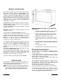
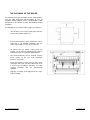
®
GHISS 70, 90, 110, 125, 145, 160, 180,
200 MAX R AE
INSTRUCTIONS FOR USE AND
OPERATING MANUAL
STANDING GAS DEVICE WITH
CAST-IRON SEGMENTED HEATEXCHANGER, SPARK IGNITION,
IONISATION FLAME-CONTROL
AND BI-LEVEL BURNER
1. VERZIÓ HU
CONFORMITY
GHISS …MAX R AE, boilers have been attested
according to the following European standards:
o 90/396/CEE gas directive
o 92/42/CEE efficiency directive
o 89/336/CEE electro-magnetic conformity directive
o 73/23/CEE low current directive
TABLE OF CONTENTS
GENERAL
Conformity......................................................................2
Important things to know.................................................3
Basic safety rules ...........................................................3
General introduction .......................................................4
Identification...................................................................4
Construction...................................................................4
Technical data................................................................6
Hydraulic operation ........................................................7
Pump .............................................................................7
Electric switching diagrams ............................................8
Operating surface...........................................................9
Dear Customer,
Thank you for choosing the gas boiler of Unical. With this,
you have become the owner of an efficient device of high
technical level and safe operation.
Congratulations!
Check the complete and intact condition of the product!
Do not remove and do not damage the signs to be found
on the device!
The present document is the operating – maintenance
manual. The guarantee slip located in the attachment is
to be stamped and filled in legibly on the occasion of the
purchase and commissioning!
We request that – in your own interest – you carefully
read the information described on the following pages,
and keep them because you might need them in the
future.
If you take our advice, our product will serve you reliably
for long years.
HANDLING THE DEVICE
Turning on....................................................................11
Setting the boiler thermostat .........................................13
Temporary shut-down...................................................13
Shutting down for a longer time ....................................14
Cleaning.......................................................................14
Maintenance ................................................................14
INSTALLING THE DEVICE
The documentation of the product ................................14
Sizes and weight ..........................................................14
The boiler room ............................................................16
Connecting the boiler to the existing old heating system16
Hydraulic connection ....................................................16
Electric connections .....................................................17
Gas connection ............................................................18
Channeling combustion products..................................18
Filling up and draining the system.................................19
SERVICE INSTRUCTIONS
Preparations for start-up ...............................................19
First start-up.................................................................19
Checking during operation ............................................21
Shutting down for a longer time ....................................22
Maintenance ................................................................22
Regulation....................................................................23
Switching to other types of gas .....................................24
The cleaning of the boiler .............................................25
The operating manual contains the following symbols:
Warning = the activity requires greater attention!
Ban = this activity must not be carried out!
2
GENERAL
VERSION 1 GB
IMPORTANT THINGS TO KNOW
After you have unwrapped the device, check whether
it is intact and complete.
Upon planning and execution, the valid requirements
of the local gas provider, the construction industrial
and environmental standards, and the prevailing
electric and other standards must be taken into
consideration and must be abided by to the full.
The manufacturer cannot take responsibility for unprofessional operation and other mechanical injuries
that emerge from unprofessional operation.
In case of failure, if you cannot eliminate the failure
on the basis of the instructions of the manual, call
the appointed brand service station.
Check the pressure of the heating system regularly,
and do not let it drop under 1 bar.
If the device repeatedly shuts down blocking, on
several occasions call the brand service; in the
meanwhile, do the following:
o Turn off the main switch of the device
o (cut off the current).
o Shut of the connected gas and water supply.
o In case of frost danger, drain the heating and
HWU water cycles (draining).
In the interest of safe and economic operation, it is
practical to have the control examination
recommended by the manufacturer and the
necessary maintenance jobs carried out on the
device by the appointed professional service station
at least once a year.
BASIC SAFETY RULES
The user is to pay attention to the fact that this device
uses gas, electric energy and water during its operation,
which poses some basic safety rules:
The boiler must not be used by children and
non-authorised persons.
Do not use electric devices, machines, equipment,
do not turn on the light if you can smell gas.
In this case, close the gas tap, air the room and
call the professional service.
Do not touch the boiler with wet hands or if you are in
your bare feet.
Do not clean the boiler while it is on and is operating.
Only the authorised professional service station can
replace safety and other parts in the device, and only
with the original factory-identical parts.
Do not pull or twist the connection cable of the boiler
while it is live.
The operation of the device requires air supplement,
therefore, do not cover or close, and do not narrow
down the vents or windows that can provide the
supplement of air necessary for burning.
Because of the danger of freezing, do not install the
boiler in an open room.
Do not store packaging materials
(cardboard paper, plastic or wood) and combustible
or explosive materials close to the boiler.
This operating manual contains all the important
information for the user in connection with the use of
the device, therefore, it is practical to keep it close to
the boiler. If the device is sold or relocated, this
operating manual is always to accompany it so that
the new owner and/or mechanic can be advised
properly.
3
GENERAL
VERSION 1 GB
GENERAL INTRODUCTION
Basic model, atmospheric furnace chamber hot water gas
boiler with cast-iron segmented heat-exchanger. It is
suitable for the realisation of the pump-system central
heating of residential and public buildings and – together
with the indirectly heated hot water containers that can be
installed next to them – for the realisation of the hot water
supply for use, as well as for any industrial-purpose
application where the 40-80 °C water temperature range
of regulation is suitable.
Its operation provides the following variations of comfort:
Winter operation: heating and/or hot water production
(the latter with preference)
Summer operation: only hot water production (heating
demand switched off)
Execution: with built-in automatic purging valve and
safety blow-off valve.
The operation of the burner system of the device:
The device has a three-point regulation, where the control
regulates the burner system of the device in such a
manner that if the temperature of the boiler is over 6 °C
below the set value, it keeps it at nominal output, if
between 6 °C and the set value, at partial load, if it
exceeds the set value, it switches it off.
Its operation is possible with piped natural gas (“H” or
“S”), (I2H,S). The gas fittings are provided with pressuregage studs of the appropriate formation, which are
suitable for the measuring of the connection (gas
network) pressure and the burner pressure (before the
nozzles).
The nominal, operating parameters of the boiler are to be
found in the “technical data” table.
The regulation of the boiler control is digital. The devices
contain weather-dependent heating control. With room
thermostats of daily and weekly programming, the
possibilities can be extended even further.
Type of the conduct of combustion products: B11BS
IDENTIFICATION
The data plate serving the identification of the boiler can
be found after the removal of the door of the device, on
the inside wall of the left-side housing.
Do not remove the data plate and do not damage it!
This data plate contains the main parameters of the
device and the individual identification information
(type, production number, date of production, etc.).
4
GENERAL
Important safety functions in the operation
of the boiler:
1. The post-circulation of the heating pump until the
temperature of the boiler drops under 38 °C.
2. After the HWU operating mode the pump works
until the water temperature of the boiler and the
temperature of the water are the same.
3. Protection of the boiler: restricting thermostat for
the prevention of the over-heating of the heating
water.
4. Protection of life: flue gas restrictor thermostat for
the prevention of the flow back of the combustion
products.
5. Frost-protection function.
6. Protection against the jamming of the pump axle.
Structural characteristics
The heat-exchanger of the boiler – depending on the
required output – is constituted by 5-6-7-8-9-10-11-12
cast-iron segments.
Its segmentation – with the insertion of special cone rings
– takes place after the segments have been pressed
together, with treaded fastening sides.
Its insulation is textile fibre-reinforced glass-wool quilt
covered with aluminium foil.
The gas fittings are provided with pressure-gage studs of
the appropriate formation, which are suitable for the
measuring of the connection (gas network) pressure and
the burner pressure (before the nozzles).
The housing of the boiler is aesthetic, covered with
electrostatic powder-painting and wear-resistant coating.
The material and construction of the structural elements
is such that during the course of the proper use of the
device – as a result of the mechanical and heat exposure
– no lasting changes of shape can take place.
VERSION 1 GB
CONSTRUCTION
The construction and main parts of GHISS …MAX R AE
type devices are the following:
The construction and main parts of the devices are the
following:
List of parts:
1. Boiler housing
2. Deflector
3. Automatic purger
4. Forward pipe
5. Dip-casing
6. Manometer
7. Pressure remote transmitter
8. Gas pipe
9. Safety valve
10. Return pipe
11. Instrument box
12. Cast heat-exchanger
13. Burner tray
14. Gas valve
15. Nozzle holder collector
16. Lifting eye
17. Support leg
5
GENERAL
VERSION 1 GB
TECHNICAL DATA
GHISS .. MAX R AE
Unit
of
70
measurement
Technical data
Nominal heat load
kW
Nominal heat output
kW
Nominal efficiency (water-side) %
Min-max operating water temperat°C
Water cubic capacity of the boilerdm3
Number of burners / main nozzlesdb
(v)
Number of cast segments
db
Heatable space
lgm3
Maximum operative overpressurebar
Boiler body test overpressure
bar
Pressure loss (80/60 °C)
mbar
Connecting sizes
Forward, return heating water
Inch
Gas connection
Inch
Gas-technical data
Piped natural gas
Connecting gas pressure
mbar
Burner nozzle pressure “H”
mbar
Burner nozzle pressure “S”
mbar
Burner nozzle diameter “H”
Ø/mm
Burner nozzle diameter “S”
Ø/mm
Ignition burner nozzle diameter Ø/mm
Heating material amount “H”
m3/h
Heating material amount “S”
m3/h
Combustion product data
Combustion product channelling Ø
Combustion product temperature °C
Required draft of the chimney mbar
Combustion product cubic capacity
Nm3/h
NOx –class
Electric data
Electric connection
V/Hz
Electric output
W
Electric protection
Shock-proofing class
Ignition flame security
Ignition
Hz/ kV
dB
Noise level
Enveloping sizes
Height
mm
Width
mm
Depth
mm
Boiler volume (without water) kg
6
GENERAL
90
110
125
71/49.7
64.6/45.2
89 / 62.3
81 / 51.7
107 / 74.9
97.4 / 68.2
125 / 87.5 143 /100.1 161 / 112.7 179 / 125.3 196 /137.2
113.8 / 79.7 130.1 / 91.1 146.5 / 102.6,1162.9 / 114 178.9 / 125.2
27
4
5
32
5
6
37
6
7
42
7
8
0.6
0.55
0.5
145
45/85
47
8
9
5 (pressure class 2)
8
0.45
0.4
160
180
52
9
10
57
10
11
62
11
12
0.35
0.3
0.25
2½
1
Classification according to the use of gas: I2H,S
12.8
15
3.5
3.9
12.8
15
3.5
3.9
7.6/5.32
8.84/6.21
9.51/6.66
11.06/7.74
200
136
200
138
1 ½”
20-25
12.9
13
13.1
15.2
15.3
15.4
3.5
3.5
3.5
3.9
3.9
3.9
0.36
11.43/8.0
13.35/9.35 15.27/10.7 117.18/12.0 19.1/13.37
12.29/9.3 15.52/10.87 17.76/12.44 19.98/13.95 22.2/15.55
Classification according to combustion product: B11BS
225
225
225
250
300
139
143
152
155
158
0.06
12.8
15
3.5
3.9
200
12.8
15
3.5
3.9
1 ½”
13.2
15.5
3.5
3.9
20.9/14.63
24.3/17.01
300
160
2. (NOx - concentration < 200 mg /kWh)
230/50
25
IP 20
I.
Ionisation
6/15 electric spark
max.50
15
15
15
25
789
939
939
1164
215
256
296
336
1095
1164
1170
376
25
25
25
1389
1389
1464
416
456
496
VERSION 1 GB
HYDRAULIC OPERATION
The hydraulic switching of GHISS .. MAX R AE type
devices
Several boilers in cascade, separated from the
consumers by means of a hydraulic shift lever
3
Radiator heating system
2
5
10
6
3
5
4
3
3
9
Legend:
1. Boiler
2. Radiator
3. Circulation pump
4. Expansion tank
5. Pressure gage
6. Safety valve
7. Rebound valve
8. Indirect container
9. Hydraulic shift lever
10. Mixing valve
Radiator heating system and indirect container
7
3
2
3
7
8
PUMP
6
No pump has been installed into these devices as the
size of that is to be calibrated primarily for the connecting
heating system. The value of the pressure loss emerging
on the boiler can be found in the technical table.
5
4
Consumers separated by means of a hydraulic shift lever
The pump must not be operated without water!
2
3
Upon the first start-up of the boiler and after a longer
period of shut-down, it is practical to check with a
screwdriver whether the axle of the built-in pump can
be turned.
5
3
4
9
Multiple-boiler cascade connection
2
3
5
6
4
7
GENERAL
VERSION 1 GB
ELECTRIC SWITCHING DIAGRAMS
GHISS .. MAX R AE
Legend:
1.
2.
3.
4.
5.
6.
7.
8.
9.
10.
11.
12.
13.
14.
15.
16.
17.
18.
8
GENERAL
Hot water for use (HWU) pump
Heating pump
Room thermostat 1-2 – switch contact, 3 – neutral wire
230 V supply voltage connection, N- neutral wire, L-phase conductor
Ignition control Nki- neutral wire, Lb-permanent phase, Lk-connected phase
Gas valve – level 2
Error signal in (7/2 – error signal out)
Flue gas restrictor
Temperature restrictor
Water shortage switch
Outside temperature sensor
HWU sensor
Boiler temperature sensor
Anti-legionella disabling / enabling
The error signal of restrictors and sensors
HWU operation disabling / enabling
Weather-dependent regulation disabling / enabling
Control panel connector
VERSION 1 GB
OPERATING SURFACE
GHISS .. MAX R AE
Legend:
1.
2.
3.
4.
5.
6.
7.
8.
Steepness regulator
Boiler regular and parallel displacement regulator
HWU regulator
Mode of operation selector
Supply voltage turned on (error indication)
Nominal output operation
Decreased output operation
Error indicator and release
The operation of the device with automatic weatherdependent regulation
- Winter mode of operation: heating and the
production of hot water for use.
- Summer mode of operation: the production of hot
water for use.
- “0” switched off mode of operation: frost-protection
function and pump periodical coerced start-up
function.
In the case of a connected exterior temperature sensor
and closed JP4 jumper, the forward water temperature
will be set automatically by the electronic system,
according to the prevailing exterior temperature. This
regulation can be influenced with the steepness setting
turn knob (1), and the heating regulator turn knob
(2), which now functions as a parallel shift regulator turn
knob. By setting steepness, we can influence to what
extent the change of the exterior temperatures should
influence the heating forward value. By increasing the
value on the regulating knob, a particular change of the
exterior temperatures is followed by a greater change in
the temperature of the water. By turning the heating
regulator knob, we can modify the whole regulating
range, by increasing or decreasing it, which increases or
decreases the permanent temperature of the heated
rooms.
9
GENERAL
The operative processes take place automatically: the
electronic device produces sparks, the burner lights, and
the gas boiler starts heating up according to the
temperature set.
- The preparation of HWU: set the required temperature
value with the regulating turn knob (3).
- Setting the temperature of the heating water: if the
exterior temperature sensor is not connected and the
JP4 jumper is open, this takes place by setting the
heating temperature regulating turn knob (2) at the
appropriate value.
Shutting down the boiler: turn the mode of operation
switch in “0” position.
In this mode of operation, the device is still under
electricity, thus it is forbidden and dangerous to one’s
life to open the switching cabinet and to undo the
electric cables! The performance of any repair or
maintenance work is possible only if the exterior main
switch or the fuse of the device has been turned off!
Warning! The ignition cable is marked with red
colour, it cannot be switched with the cable of the
flame-guard because then the boiler will become
unable to operate.
VERSION 1 GB
Troubleshooting
If ignition does not take place automatically, the error
indicator lamp press button (8) is lit – the operation of the
burner head can be checked through the peephole.
Upon pressing the error indicator lamp press button, the
error indicator lamp goes out, the automatic ignition
process is repeated.
switches off, and the pump post-circulates for another
120 seconds. In case of a connected indirect container,
the device has an “Antilegionella” function. The function
can be switched on by putting the short-circuit caps on
the JP1-JP2 jumper legs. With the function turned on,
once a week the device heats up the boiler to 65 °C.
If the boiler has not been operative for a long time or has
not been operated ever, it is natural to repeat the
process several times as the gas system filled with air
has to be ventilated.
When it is turned on, the device starts with this function,
and starts the weekly cycles from here. The device is
equipped with a temperature restrictor(s), by which
security (locked) turning off is performed during the
operation of the boiler:
In the event of several unsuccessful attempts, call the
colleagues of Unical Márkaszerviz.
1. In the case of unsuccessful ignition or missing flame,
These types work properly only in the event of
phase-spot electric connection!
The operation of the gas device
The temperature of the heating water can be regulated
between 45-80 °C but according to the heating demand,
the operating temperature of the boiler is to be chosen in
such a manner that the temperature of the return heating
water is not lower than 45 °C. Below this temperature,
the combustion product may get condensed, and the
settling steam may lead to the corrosion and failure of
the boiler body.
During operation, keep the door of the gas boiler
closed!
After lighting, the gas burner operates at low output for
30 seconds, then it switches to nominal output. At 38 °C
of the boiler water, the circulation pump switches on.
When the temperature of the water approaches the set
value by 6 °C, the device switches to decreased output.
Upon reaching the set water temperature, the main
burner switches off. If the forward temperature drops 4
°C below the set value, it switches on again with
decreased output. If the forward water temperature
keeps decreasing, by 7 °C under the set value, it
switches to full output again.
Naturally, the heating process described only takes
place if the room thermostat is turned on. When the
room thermostat is turned off, a heating cycle is finished
and a 300-second long interval is started, within which
the heating pump post-circulates for 120 seconds or until
the heating water drops under 38 °C. The boilers have a
frost-protection function. The temperature of the forward
water drops under 8°C, a 120-second long watercirculation is started, after which, if the temperature of
the water increases above 8 °C, the pump stops, but if
the temperature of the water still remains under 8 °C, the
circulation cycle starts again. When the temperature of
the water drops under 5°C, the decreased output of the
burner starts, then after 30 seconds, it operates with full
output until it reaches 39°C. Above 39°C, it heats with
decreased output until it reaches 45 °C, when the burner
10
GENERAL
2. In case of the intervention of the water temperature
separator 96°C, its display is indicator 5.
3. In case of the intervention of the flue gas temperature
separator thermostat 90°C, its display is indicator 5.
4. In the event the water pressure switch is turned off.
It is strictly FORBIDDEN to eliminate the safety,
intervention fixtures!
Signs of disorder
The LED on the operating surface (5) warns of the
possible failure and locked stoppage of the NTC
sensors and restrictors by blinking.
Attention!
The device is allowed to be restarted only after the
reason leading to its stoppage has been eliminated! For
the re-start, the door of the device is to be opened, and
the locking-release button located on the left side of the
first connecting sheet must be pressed.
Do not miss to use the appointed service station!
Do not endanger your safety and the safety of your
environment by unprofessional interventions!
The flow-back of the combustion product may lead
to death!
The replacement of broken parts can be carried out only
by the appointed professional service station and only
with original factory parts! The replacement of broken
safety separator thermostats can be carried out only
after the operation test of the new part has been
performed!
Attention! Unical Kft. assumes no responsibility for
damage caused by neglecting the above warnings!
VERSION 1 GB
TURNING ON
Automatic mode of operation
These devices do not require the manual handling of the
gas valve as the device works automatically by simply
setting the operating devices placed on the front sheet of
the boiler to the desired value, according to the following.
-
Turn on the exterior mains switch.
-
Open the gas tap and the water-side closing fixtures.
-
In the case of the connection of an exterior
temperature sensor, set the values of steepness and
parallel shifting according to the nature of the
heating system and the building. (1, 2)
-
In case of the manual mode of operation, if there is
no exterior sensor, set the boiler regulator
thermostat (2) according to the desired temperature.
-
Set the mode of operation switch (4) according to the
desired mode of operation:
Winter mode of operation – heating and the production
of hot water for use at the indirect container connected to
the boiler.
Summer mode of operation - the production of hot
water for use at the indirect container connected to the
boiler.
The following processes take place automatically: the
electronic system produces sparks, the burner lights,
and the gas boiler starts heating-up according to the set
temperature value.
The setting of the desired hot water temperature at the
connected indirect container, with the hot water for use
regulator (3).
11
HANDLING THE DEVICE
VERSION 1 GB
After a long pause of operation, it may happen that the
device does not start up. In this case the following is to
be checked and performed:
o
Check whether the taps of the gas and water, as
well as of the heating system are open.
o
Check if the heating system is filled up, there
has to be at least 1 bar pressure.
o
Turn off the exterior separator switch of the
boiler, then back on again.
o
Check the setting of the room thermostat and
turn it off and on.
o
o
In the case of manual mode, if there is no
outside sensor, set the boiler regulator
thermostat (2) at the desired temperature.
Set the mode of operation switch into winter
mode (4).
In the summer mode, the boiler only performs the
production of hot water for use if there is an indirect
container connected. Otherwise the device does not
work in the summer mode setting.
12
HANDLING THE DEVICE
VERSION 1 GB
o
o
o
The operation of the boiler is started and lasts
until the boiler water temperature reaches the
set temperature value, or the room thermostat
switches off.
In the event of an ignition error, the illuminated
reset push button lights up with red light.
The process of re-starting is the following:
- Press the reset push button,
- Wait until the ignition procedure is
repeated, and operation is started.
If the ignition procedure is unsuccessful again, restarting can be repeated after a minute or two. The
number of repeated re-starting can be maximum 3. After
this call the brand service.
SETTING THE BOILER THERMOSTAT
When the outside temperature changes, the heating
temperature is also to be changed. The colder the
outside temperature is, the hotter heating water we
need. With weather-dependent regulation this takes
place automatically.
In the case of manual mode of operation, to increase the
temperature of the heating water, the heating
temperature regulator button is to be turned clockwise;
turning it anti-clockwise decreases the temperature of
the boiler. To avoid condensation, the forward
temperature set must be at least such that the
temperature of the return water is above 40°C.
TEMPORARY SHUT-DOWN
If, because of a holiday, excursion or some other reason,
you want to turn off the boiler, you have to do the
following:
o Turn the mode of operation switch of the boiler to
“0” position, the mains indicator is lit.
o
13
You have nothing else to do: in the stand-by
mode of operation only the protective functions
of the boiler operate, which are frost protection
and the axel movement of the pump.
HANDLING THE DEVICE
VERSION 1 GB
SHUTTING DOWN FOR A LONGER PERIOD
OF TIME
In this case the following is to be done:
o Turn the mode of operation switch of the boiler to
“0” position, the mains indicator is lit.
If there is danger of freezing, drain the water
from the heating and HWU systems.
CLEANING
The outside housing of the boiler can be cleaned with a
soft, wet cloth with some detergent. In case of stubborn
soiling, removal can be executed with a cloth dampened
in the mixture of 50% denaturated alcohol and water.
The cleaning of the boiler body and smoke ducts is
to be carried out by the professional service station,
at regular intervals.
o
Turn off the exterior separator switch of the
boiler.
Do not use rough scouring agents!
Before you start the cleaning of the boiler, turn off
the main switch of the boiler and the exterior
separator switch.
MAINTENANCE
o
The regular maintenance and check-up of gas devices is
specified by EU directives and standards. Professional
and experienced service stations trained for the model
secure the following for your device:
o Greater security;
o Abiding by the legal requirements;
o Decreasing the chances of technical failures.
Close the water tap.
THE DOCUMENTATION OF THE PRODUCT
The manual and list of services belonging to the product is placed on top of the device, in a plastic bag, inside the
packaging.
After the device has been unwrapped, you will find
the documentation; read it carefully and abide by
the advice and instructions written there.
14
HANDLING THE DEVICE
VERSION 1 GB
SIZES
GHISS .. MAX R AE
GHISS MAX
70
90
110
125
140
160
180
200
15
INSTALLING THE DEVICE
A
789
939
939
1164
1164
1389
1389
1464
B
1008
1008
1008
1008
1008
1008
998
998
C
320
386
386
487
487
588
588
649
ØD
200
200
225
225
250
250
300
300
VERSION 1. HU
THE BOILER ROOM
UNICAL GHISS MAX boilers are allowed to be fitted only in rooms where the necessary supply of air (ventilation),
required by the standards, is provided for the device, and which meet the fire safety and other requirements.
CONNECTING THE BOILER TO THE EXISTING OLD HEATING SYSTEM
If we connect the boiler with an old heating system, the following is to be abided by:
o The diameter and height of the chimney is to meet the new requirements, it must be of the sufficient cleanness, and
provide the necessary amount of draught.
Water quality values
o The electric system is to meet the regulation requirements of PH
the boiler.
Electric conductibility
< 200 mV/cm (25°C)
o The pipes and fixtures of natural gas and gas are to secure the
Chloride ion
< 50 ppm
amount and pressure of fuel required for the boiler according to
Sulphuric acid ion
< 50 ppm
the standards.
Sum
total
iron
contents
< 0,3 ppm
o The closed expansion tank of the system is to be of the
Alkaline
metals
< 50 ppm
sufficient size and pre-tension pressure so that it can
Hardness
of
water
35°F
compensate for the changes of pressure of the system due to
Sulphur
ion
none
changes in temperature.
none
o The output of the heating circulation pump, as well as the place Ammonia ion
Silicon ion
< 50 ppm
and direction of installation are to meet the new requirements.
o The hydraulic system is to be free of air and sediment. This can be achieved by means of the thorough cleaning of the
system before connection. Better results can be achieved by means of washing through with chemicals.
o The requirements towards the chemical composition of the water of the system can be found in the table.
HYDRAULIC CONNECTION
The connection place of the heating system and the system of water for use to the boilers is illustrated by the following
figure.
Choosing the type that best fits the heating system of the building is the task of the designer.
If need be, the heating system can also be filled up with anti-freeze liquid.
16
INSTALLING THE DEVICE
VERSION 1. HU
ELECTRIC CONNECTIONS
The devices have the following electric connections.
Mains connection 230 V 50 Hz, room thermostat
connection, heating and hot water for use pump
connection,
exterior sensor connection.
These
connections can be found inside the instrument box, are
of serial connection, and are equipped with proper
labels.
Access is provided in the following way:
o
o
Remove the top of the boiler, which is fastened
by snaps.
Unscrew the screws of the lid of the instrument
box, and you will have access to the connecting
switches.
There is a 230 V 50 Hz present on the
connections of the device, therefore, to avoid
accidents, before you remove the lid of the
instrument box, turn off the exterior separator
switch!
o
o
The connection of the room thermostat may be
on two cables or – if the operation of the
thermostat requires it – of three cables.
The exterior sensor is to be connected with a
double-core cable.
When connecting the pumps, pay attention to
the fact that the connections can be loaded with
maximum 1A! If you have to operate a stronger
or a 3-phase pump, the exit is to be separated
by means of a relay or magnetic switch.
17
SERVICE INSTRUCTIONS
VERSION 1. GB
1.
2.
3.
4.
5.
The following rules are to be abided by at the
electric connections:
Connect the mains cable polarity correct to the
electric network. The length of this can be
maximum 3 m.
Marking at the connection: L – phase conductor, N
– nil conductor.
The recommended cross section of the connecting
2
cables is 1.5 mm , a hose conductor free of
injuries.
Connection is to be carried out according to the
electric connection diagram.
The connection of the protective conductor is
compulsory.
Gas or water pipes must not be used for the
protective cable! The boiler and the pipe-system
must be connected with the shock-protection
system with standard protective conductor.
The manufacturer undertakes no liability for
incorrect installation!
CHANNELING THE COMBUSTION
PRODUCTS
Connect the boiler with the chimney according to the
valid standards and specifications.
Connection is to be executed with stiff pipes, providing
sufficient caulking, also counting on possibly forming
condensation water. The mechanical fastening of the
connecting pipes is to be secured against movement and
slipping out.
The boilers are equipped with flue gas restricting
thermostats, which – if the flue gas flows back –
switches off the operation of the boiler in a locked
manner.
The use of an un-insulated exterior chimney poses
potential dangers.
The connection of GHISS MAX devices to the chimney.
GAS CONNECTION
Only piped natural gas can be connected to the device.
Before you carry out the connection, the following is to
be executed:
o Check the cleanness of the gas pipe and if
necessary, a filter is to be installed before the
boiler.
The gas connection is to provide gas of the
appropriate amount and pressure, and the proper
functioning of the measuring and security systems
is to be checked.
After you have connected the device with the gas
system, check the intact condition of the seal and
whether the standards are abided by.
The air necessary for the operation of the boiler is to be
provided through door and windows on the walls of the
room or ventilation grates!
Providing air, ventilation
-
-
The connecting size of the gas pipeline between 70 and
160 is 1”, and between 180 and 200 is 1 ½”.
18
SERVICE INSTRUCTIONS
-
The replacement of the air of the room where the
device is should be at least five-fold per hour! With
devices with an output of over 140 kW, if the value of
3
the load on the air is over 1100 W/m , lamellar opening surfaces are to be provided on the walls or
the roof. If the nature of the building does not allow
this, it is compulsory to use a gas sensor. Over
3
specific load of 2800 W/m on the air 2 gas sensors
operating independent of each other are to be
installed!
If the air-supply of the room takes place through an
opening provided with a closing fixture (flap, mobile
shutters, etc.) or through a pipe, the gas supply of the
device is to be locked with this.
With artificial ventilation, the gas supply of the device
is to be locked with the ventilation device in such a
manner that in the event of the absence of the
ventilation air the device could not be operated.
Only blow-in (over-pressure) ventilation can be used
for artificial ventilation.
VERSION 1. GB
FILLING UP AND DRAINING THE SYSTEM
No filling-draining tap has been installed into these
devices, therefore, upon the establishment of the heating
system, the installation of this must be provided at the
lowest point of the return pipe.
Before you start to fill up, the following is to be done:
o Turn off the main switch of the boiler.
o Open the filling tap until the pressure of the
system reaches 1.5 bar.
o Close the filling tap.
o Turn on the boiler.
Draining:
o Before you start draining, turn off the boiler.
o Open the draining tap.
PREPARATIONS FOR START-UP
Before you turn on the device, remove the door of the
boiler and check the following:
o The taps of the heating system and the gas
connection are open.
o The type and connection pressure of the gas is
suitable for the device.
o The pressure of the heating system when cold is
over 1 bar, and it has to be free of air.
o The pressure of the expansion tank before the
system is filled up, must be 0,8 ~ 1 bar.
o The connection of the electric system is suitable
for the device.
o The connection of the combustion product
conducting channel (chimney) is suitable.
FIRST START-UP
Do the following for the start-up of the device:
o Turn on the exterior separator switch.
o
Set the room thermostat for the desired value.
o
Set the mode of operation switch in winter
position.
In the summer position, the boiler only produces
hot water for use, if there is an indirect container
connected and the JP3 jumper is short-circuited.
Otherwise the device does not work in summer
position.
o
19
Set steepness and the parallel shifting regulator
at weather-dependent mode of operation, and
the boiler regulator thermostat at manual mode
of operation, for the desired temperature.
SERVICE INSTRUCTIONS
VERSION 1. GB
The ignition procedure of the boiler starts, sparks are
produced automatically, then operates continuously until
the boiler or the room thermostat switches off.
In the event of an ignition fault, the illuminated re-set
push button is lit in red.
The process of re-starting is the following:
- Press the re-set push button,
- Wait until the ignition procedure is
repeated and operation starts.
It may happen that during continuous operation the
boiler stops and the error indicator light flashes (the top
one).
For re-setting, do the following:
o
o
Remove the door of the boiler, fastened by
snaps.
On the first connecting sheet, there are two
hexagonal plastic protective caps. Twist them
off, and under them are two push buttons. The
left-side is the flue-gas restrictor, the right-side is
the temperature restrictor thermostat.
o Push in the buttons as far as they go. At the
thermostat that was turned off, you will hear a
click upon pushing, and the error-indicator light
goes out, and the ignition of the device is restarted.
20
SERVICE INSTRUCTIONS
VERSION 1. GB
CHECKING DURING OPERATION
After start-up, the following is to be checked:
o The mode of operation switch of the boiler off,
then switching to winter mode of operation.
o
o
The operation of the boiler control (parallel
shifting) by turning the boiler temperature button
left, then right.
The operation of the room thermostat by turning
it off and on.
After the room thermostat has been turned off
and on, the boiler restarts only after 5 minutes!
o
The operation of the pump.
o
The operation of the exterior separator switch by
turning it off and on.
o
21
If everything is operating perfectly, then checking
the draught of the chimney and the firingtechnical calibration follows.
SERVICE INSTRUCTIONS
VERSION 1. GB
SHUTTING DOWN FOR A LONGER TIME
In this case, the following is to be done:
o
Turn off the mode of operation switch of the
boiler.
o
Turn off the exterior separator switch of the
boiler.
o
Turn off the gas tap.
If there is danger of freezing, drain the water
from the heating and HWU systems.
MAINTENANCE
On the basis of standards and regulations, the gas
device requires regular maintenance and periodical
check-ups. This increases the operational safety of the
system, and through the maintenance, it is secured that
the device always operate with utmost efficiency, and
thus the consumption of gas is the lowest.
Before you start maintenance:
o Turn off the separator main switch.
o
22
Turn off the tap of gas-connection.
SERVICE INSTRUCTIONS
VERSION 1. GB
REGULATION
In the factory, the boilers are calibrated for piped natural gas (G20), which is indicated on the boilers with a sign! The
value set may diverge from the value given by ±5%. The calibration values can be found in the table below. These are
needed because after a possible repair it is necessary to carry out calibration; calibration is also necessary if the gas type
has to be switched.
The gas-technical calibration of the gas device and switching to another type of gas can only be carried out by the
members of a professional service station!
The method of switching to other types of gas will be introduced below.
GHISS 70
GHISS 90
GHISS 110 GHISS 125 GHISS 145 GHISS 160 GHISS 180 GHISS 200
G20 G25.1 G20 G25.1 G20 G25.1 G20 G25.1 G20 G25.1 G20 G25.1 G20 G25.1 G20 G25.1
“Wobbe index”
45.7 37.4 45.7 37.4 45.7 37.4
[MJ/m3]
Nominal pressure
20-25 20-25 20-25 20-25 20-25 20-25
[mbar]
Minimum pressure
17
17
17
17
17
17
[mbar]
Number of nozzles
4
5
6
[db]
Nozzle size Ø
3.5
3.9
3.5
3.9
3.5
3.9
[mm]
Nozzle pressure
12.8
15
12.8
15
12.8
15
[mbar]
Gas consumption
7.6
8.8
9.5
11.1 11.4 12.3
[m3/h]
45.7
37.4
45.7
37.4
45.7
37.4
45.7
37.4
45.7
37.4
20-25 20-25 20-25 20-25 20-25 20-25 20-25 20-25 20-25 20-25
17
17
174
7
17
17
8
17
17
9
17
17
10
17
11
3.5
3.9
3.5
3.9
3.5
3.9
3.5
3.9
3.5
3.9
12.8
15
12.9
15.2
13
15.3
13.1
15.4
13.2
15.5
13.4
15.5
15.3
17.8
17.2
20
19.1
22.2
20.9
24.3
The data of the table have been provided for 15°C and 1013 mbar air pressure.
The pressure of the nozzle can be checked in two
places. First, on the gas valve control studs, but this can
be used only on devices with one gas valve; the other is
the control stud at the end of the nozzle holder collector.
The connection pressure can be checked at the stud
marked “B” on the gas valve.
o Connect the pressure gage on the measuring
stud.
o Start up the boiler in the manner introduced
above.
The regulation of the gas burner:
Loosening the screw of the measuring stud on the gas
collector.
Connecting the pressure gage or U-pipe manometer.
Turn on the gas device and set the temperature
regulator at maximum.
Remove the closing cap of the gas valve.
1, In the event of one gas valve:
Set the gas pressure to the value given in the table based on 100% output - when the display of the
device indicates operation with normal output. You
can carry out the setting by turning the hexagonal
(outside) screw of the gas valve. If you turn it to the
right (inside), the pressure of gas increases, if to the
left, it decreases.
23
SERVICE INSTRUCTIONS
Pull off one of the connectors of the modulation coil of
the gas valve, and set the pressure value belonging
to the decreased output. You can carry this out by
twisting the medium, grooved-head screw. The value
of this is determined by local features. Recommended
value: between 5 and 8 mbar. Attention, the
connection leg pulled off might be live, so it must not
be touched as it may cause electric shock! After
calibration, place back the connector.
2, In the event of two gas valves:
Open one of the valves to the maximum (turn the
hexagonal screw as far as it goes, then a quarter-turn
back), then set the gas pressure on the second valve
to the value specified - on the basis of 100% output when the display of the device indicates operation
with normal output.
Pull off one of the connectors of the modulation coil of
both gas valves, and set the pressure value
belonging to the decreased output on the second
(ancillary) valve. If, during the calibration, you cannot
decrease the value of gas pressure sufficiently,
calibration is to be completed on the first valve. The
value of this is determined by local features.
Recommended value: between 5 and 8 mbar.
Attention, the connection leg pulled off might be live,
so it must not be touched as it may cause electric
shock! After calibration, place back the connector.
VERSION 1. GB
Twist back the closing screw of the gas valve.
Turn off the gas device, remove the gage and close
down the measuring stud of the gas collector.
Turn on the gas device, after lighting up, check the
compactness of gas along the full gas line.
SWITCHING TO OTHER TYPES OF GAS
During production, the boilers were manufactured and
calibrated for natural gas type G20.
Switching the device to another type of gas and its gastechnical calibration can only be carried out by the
professional service station!
Switching to another type of gas, e.g. G30 (propane)
requires the following steps:
The replacement of nozzles
o Remove the door of the boiler
o Screw out the nozzles from the collector and – in
their place – screw in the nozzles of the sizes in
harmony with the gas type. Use the washers!
Gas-technical regulation
After the replacement of the nozzle, carry out the gas
pressure calibration of the nozzles in the manner
described in the chapter entitled “The calibration of the
gas burner”.
When calibrating the device for another gas type, the
size of the nozzle and the value of gas pressure are to
be the same as the values specified in the table
introduced above!
o
o
24
Check the compactness of the whole pipe
system.
Remove the “Calibrated for G20” sign posted
under the gas connection, and post the label
referring to the current gas type in its place.
SERVICE INSTRUCTIONS
VERSION 1. GB
THE CLEANING OF THE BOILER
The exterior housing of the boiler can be cleaned with a
soft, wet cloth dampened with detergent. In case of
stubborn soiling, removal can be executed with a cloth
dampened in the mixture of 50% denaturated alcohol
and water.
It is forbidden to use paint or other, aggressive thinners!
o
o
o
o
o
o
25
You will have access to the inside parts after the
removal of the door and the lid.
If the instrument box is to be removed, it can be
pulled out in “B” direction (forward) after the
snaps marked with “A” have been released.
To remove the gas burner, release flare nut
number 1, then, after the twisting out of screws 2
of the burner tray, it can be lifted out forward.
The removed burners can be cleaned, and the
inside surface of the cast heat exchanger
becomes accessible.
Check the cleanness of the surfaces of the heatexchanger and if you can find settled soot, clean
it. If the layer of soiling is too thick, use sootremoval chemicals that are commercially
available.
Logically, assembly is the opposite of the steps
of disassembly.
SERVICE INSTRUCTIONS
VERSION 1. GB
26
SERVICE INSTRUCTIONS
VERSION 1. GB