1
Installation and Operating Instructions
ZW 05 DCU
Universal Microprocessor-Driven Charge Control
(0.91 to 1.43 V and -3.60 to -2.85 V DC)
with Timer Function
Microprocessor-driven charge control (DC-universal) for underfloor storage heating and electric storage heaters with DC
charge control (output signal 0.91 to 1.43 V and -3.60 to -2.85 V DC).
Table of Contents
Contents
Unit Description
Technical Information
Operating Instructions for Users
Input Menu for Users
Installation and Operating Instructions for Technicians
Charge Control Set-Up
Activation Examples
Connection Diagrams
Setting the Charge Control
Setting Examples
Input Menu for Technicians
Start-Up
Start-Up Protocol
Correcting Basic Settings
Diagnostic Information
After-Sales Service
2
Page
3
3
4
5
7
8
9
10
13
14
15
20
21
23
23
24
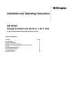
Unit Description
The ZW 05 DCU microprocessor-driven charge control
controls the charging of an underfloor storage heating
and/or the charging of storage heating devices
according to outside temperature, settings and control
signals.
It has the following features:
Charging according to external temperature,
Initial heating program for screed flooring,
Timer function for backward, intermediate and forward
control,
Priority and secondary use of actual service release
periods for low and high tariffs,
Adjustable detection of service release period (charge
release detection)
Direct control via charge control line Z1+/Z2- is possible,
Automatic correction of charging during extreme
temperature fluctuations (daytime and night-time
temperatures) in transition periods, via external
temperature averaging,
Characteristic curve switching via external control
is possible,
Large, back-lit, alphanumeric multi-function display
showing operating status and service information,
All utility company requirements can be met,
Optional connection to NTC or older PTC external
sensors,
Real-time timer to lower charging (weekly programme
and absence of up to 30 days).
Scope of delivery
- The ZW 05 DCU microprocessor-driven central control
unit
- NTC external sensor with 2 m connecting lead
- Installation and operating Instructions
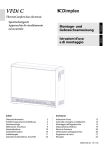
Technical Information
ZW 05 DCU microprocessor-driven charge control
Connection voltage
Power consumption
Reference variable at the Z1+, Z2- terminals:
Reference variable at the I2, I1 terminals:
Number of charge controllers that can be activated
Power reserve
Switching capacity of safety output
Ambient temperature
Protection class
Degree of protection
Standard
Space requirements
Attachment
Connection terminals
Dimensions
Weight
1/N/ 230 V AC ~ 50/60 Hz
Approx. 2 VA
0.91 V to 1.43 V DC, safety overlap to 1.68 / 1.95 V
-2.85 V to -3.60 V DC, safety overlap to -4.35V
100 maximum
Approx. 6 hours (runtime and timer)
6A, 230 V ~
Between 0 °C and 50 °C
II according to installation (see section on “Installation”)
IP 20, according to DIN 40050, according to installation
DIN EN 50350 and DIN 44576 (draft)
6 x DIN 43880 modular spaces
Top hat rail
15, cross section 2.5 mm²
See dimension drawing
Approx. 320g
External sensor
Sensor type
Connecting pipe
Protection class
Degree of protection
Dimensions
See dimension drawing
NTC sensor according to DIN EN 50350 in insulated casing
2 m long (extendable up to a maximum of 30 m)
II according to DIN EN 60730-1
IP54 according to DIN 40050
105
10
S
KV
I1
I2
1
2
3
D im p lex
50 mm
LL
AT M
LF
Abw
LZ
LF Ü
E5
AT W
E2
E4
KU
KV
E3
E 15
E 10
E1
230V
L
4
50 Hz
N
5
LL
LF
LZ
KU
6
7
8
9
83
ZW 05D CU
D C - Z e n t r a ls t e u e r g e r ä t
2 VA
12
MODE
E - N r. : 2 1 /0 3 0 1 ( 0 1 )
6A
SH
KV
Z1
Z2
W2
W1
10
11
12
13
14
15
3
Operating Instructions for Users
For underfloor storage heaters, the controller set point is
determined by the amount of applied control voltage and
position of the intensity actuator E8/KT (daytime) or E7/KN
(night-time) on the charge controller. The actual value of
charging for any heating circuit is displayed on the charge
controller via the residual heat sensor in the insulating
screed. For storage heaters, the controller set point
depends on the applied control voltage and the position of
the charge selection button.
The actual value of charging is determined via the residual
heat sensor by measuring the core temperature. The charge
controller compares the set point with the actual value and,
if necessary, switches on the charging until the required
heat content is reached.
General Information
For installation, operation and maintenance, please observe
these installation and operating instructions. This unit
should only be installed and repaired by an experienced
technician. Poorly carried out repairs can endanger the
safety of the user. In compliance with VDE (association of
German engineers) regulations, the installation and
operating instructions must always be available and should
be given to the technician working on the unit for his/her
information.
Should ownership change, these installation and operating
instructions must be passed on to the new user or owner.
This is how your heating system works
Setting the charge controller of an underfloor heater
The local utility company makes electricity available for
electrical heating purposes during periods in which other
customers require little or no electricity – so-called off-peak
periods.
Utility companies offer electricity at discounted tariffs
primarily during the night-time release period. In certain
service areas, electricity for heating purposes is additionally
available during the daytime – the so-called additional
release period. For release and additional release periods,
the tariff conditions may vary. Information can be obtained
from your authorised electrician or local utility company.
The specified charging periods are generally released via a
control unit (ripple control receiver or timer) by the utility
company. The ZW 05 DCU microprocessor-driven charge
control ensures consumption-based charging of your
storage heater.
To ensure the utility company’s technical connection
requirements are met, your electrician will carry out the
precise setting of all required values on the central control
unit and the charge controllers.
Night-time charging (E7/KN) and daytime charging (E8/KT)
can be corrected for each heating circuit via the charge
controller. Night-time charging affects the room temperature
during the early morning and late morning, whereas the
daytime charging affects the room temperature in the
afternoon. Setting information can be found in the
corresponding operating manual.
Setting the intensity actuator (charge selection button)
on a storage heater
During automatic operation, the intensity actuator is set at
the right-hand stop (factory default), i.e. the storage heater
charges at the value specified by the ZW 05 DCU
microprocessor charge control.
In areas with reduced heating needs, e.g. bedrooms,
charging of the storage heater can be reduced and the
storage heater adjusted by turning the charge selection
button to the left. No charging takes place at the left-hand
stop.
During automatic operation operating errors and
unintentional re-setting can be prevented by removing the
controller button from the storage heater’s intensity actuator
and covering with the closing cap.
Should no charging of the storage heater be necessary in
the summer months (even on cooler summer nights), we
recommend taking the entire heating system out of
operation. For more information consult your authorised
electrician. Please observe the technical connection
requirements of your local utility company.
Central control and charge controller
The ZW 05 DCU microprocessor-driven charge control
measures the weather conditions and the inertia of the
building, via the external sensor located in the brickwork.
This reference variable is connected to the various settings,
runtime and, depending on the signals of the control
terminals, to the central control unit’s output variable (set
charge rate = control voltage to Z1+/Z2- or I1/I2). The
control voltage is transferred to the electronic charge
controller, which functions as the ON/OFF controller.
The heat storage capacity of the entire heating system can be raised or lowered at the charge control.
Weekly
programme
On
Multifunction
display
4
D im p le x
MODE
LL
ATM
LF
Ab
LZ
LFÜ
E5
AT W
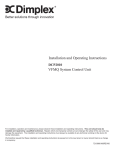
Rotary switch
LED
E2
E4
KU
KV
E3
E15
E1
E 10
D C - Z e n tra ls te u e rg e rä t
Z W 0 5 D CU
E - N r.:2 1 /0 3 0 1 ( 0 1 )
Forward button
Plus button [+]
Backward button
Minus button [-]
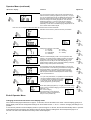
Input Menu for Users
During normal operation, the unit is in operator mode. The “mode” LED does not light up.
Therefore, the menu item shown in the display depends on the position of the rotary switch as well as the setting of the ANZ
(display) menu item. During normal operation, the individual menu items of the operator menu can be accessed with either the
forward button [▼] or the backward button [▲]. Individual menu items can also be directly obtained via the rotary switch.
Adjusting the flashing setting parameters is possible via the "plus" [+] or "minus" [-] buttons.
Changes will be made automatically with this adjustment. If 3 minutes should elapse and no adjustment has taken place, the
control unit automatically changes back to the selected display status and the changes saved.
Menu item / display
Comment
Adjustment
Time and day of the week are displayed in the operating mode
“timer function” UHR = JA (timer = yes) and ANZ (display) = Uhr
(timer) or ANZ (display) = AU (off)
START Operator Menu
Runtime LA
Displays time elapsed since the start of night-time charging
release period (start of the charge release LF)
(Note: during active release synchronisation with timer (FSU) =
JA (yes), runtime adjustment is locked.)
Charge level E5
Changes to the basic charge level of all storage heating systems
connected to the charge control. The set charge can be either
proportionally raised or lowered by 30%, according to need. The
change to the charge level should only be made gradually, since
the effect of these changes will only become apparent after the
unit has been charged.
Charging start E2
Specifies the effective external temperature (ATW) at which
storage heater charging should begin. (The higher the selected
setting, the sooner charging will start and, thus, the higher the
set charge amount is at the same effective external temperature
ATW).
Base charge start E15
Specifies the minimum charging base to which the effective
external temperature may fall when set according to E2.
Recommended setting:
Insufficient charging in the transition period: raise E15 by 5% to
10%.
Excess charging in the transition period: lower E5 by 5%.
Additional charging (daytime charging) E10
Reduction or increase of an available daytime recharging E10 =
0% means no recharging in the afternoon, independent of the
effective external temperature.
Note: In the event that the daytime charging via the TAS
(daytime skip) adjuster (TAS = E1 or TAS = TE; only technician
has access) with higher effective temperatures is fundamentally
disabled, then the E10 adjuster is ineffective above these
temperatures.
Effective external temperature ATW
Displays the effective temperature at external sensor location
Not possible
ATM (external temperature averaging) = 1:
ATW (effective external temperature) refers to the averaged
temperature
ATM (external temperature averaging) = 0:
ATM corresponds to current temperature
5
Operator Menu (continued)
Menu item / display
Comment
Adjustment
Real-time – timer
The microprocessor-driven charge control is equipped with a
real-time function (weekly programme) (Uhr (timer) = JA (yes)).
This can be utilised either strictly as additional information or for
automatic charge lowering during longer periods of absence
and/or according to the weekly programme. This offers the
additional possibility, in connection with the FSU (release
synchronisation with timer) = JA (yes) function, to release or
individually conceal time-controlled charging independent of the
time in areas without release signal.
Note: This can no longer be switched off after the real-time timer has been activated!
Extended runtime function (real-time function) is activated
Setting the time
Setting the current time
Day
Setting the current day of the week:
T1 = Monday
T5 = Friday
T2 = Tuesday
T6 = Saturday
T3 = Wednesday
T7 = Sunday
T4 = Thursday
Display
Selection of desired display mode in normal operation ANZ
(display) = AS (switch position indicator): display according to
the position of the rotary switch ANZ (display) = Uhr (timer):
displays the time and day of the week ANZ (display) = AU
(switch position indicator, timer): automatic switching of display
between rotary switch position and time/day
Days of absence
For the duration of the days selected (between 1 and 30), the
KU (characteristic curve switching) is activated according to the
KUT (characteristic curve switching, temperature) or KUP
(characteristic curve switching, percent) setting parameters.
After the period of absence has elapsed, the normal charge
curve is switched back to.
Weekly programme
For cyclic user preferences, it is possible to choose between
normal and lowered charging via the weekly programme.
The active weekly programme is denoted
in the display by the “Wochenprogramme”
(weekly programme) symbol (WoP).
Day
When WoP (weekly programme) = JA (yes), the desired charge
curve (normal or lowered charging) can be set to any day of the
week (Mo – Su).
Nor: normal charging
KU (characteristic curve switching):
reduced KU charging activated as of
8:00 pm on the previous day
End of Operator Menu
Changing to the technician menu in the display mode.
If the forward button [▼] be held down for approx. 10 seconds, the unit will switch to this mode. The LED display (green) is lit
during display mode and the configuration settings can be accessed via the "" and "" buttons. Changing the settings is not
possible.
If no button be pushed in the active display mode for a period of approx. 3 minutes, the unit will automatically return to operator
mode after this time has elapsed. The display mode can also be ended by holding down the forward) button [▼] for 10
seconds. The menu item selected via the rotary switch will be displayed.
6
Installation and Operating Instructions for Technicians
Installing the central control unit
Installing the external sensor
Installation may only be carried out by a technician
authorised by the respective utility company. The
regulations of the local utility company as well as the
relevant VDE (association of German engineers)
regulations are to be observed.
The unit requires 6 DIN 43880 modular spaces. Protection
against accidental contact according to protection class II is
ensured by:
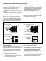
The NTC external sensor should be installed at least 2 m
over the floor in the outer brickwork, preferably within the
zone of main use (for large systems), or in the room of main
use (for single systems). The sensor should not be subject
to direct sunlight. Heat sources (e.g. ventilation shafts or
open windows) must not affect the sensor and, thus, the
ZW 05 DCU microprocessor-driven charge control.
Please observe the following:
Installation in a small distribution board according to DIN
57603/VDE 0603 (e.g. N system distribution board)
Installation in a distribution board according to DIN
57659/VDE 0659.
The charge control unit should be installed in the coolest
location, i.e. the lowest mounting row of the distribution
board. Please ensure a clearance of at least one modular
space on both sides.
The unit comes complete with lead-sealable cover caps,
The external sensor must be embedded in the mortar
The cable feedthrough must be carefully protected with
thermal insulating material.
The NTC external sensor contains a 2-m long connecting
lead, which may be extended to a maximum of 30 m using
an installation lead (1.5 mm² minimum).
which are to be used for installation in the installation
distribution board only. These must be removed before
installation.
Wall with outside insulation
Outside
Wall with or without inside insulation
Inside
Brickwork
Outside
Inside
Brickwork
Concrete
External sensor
External sensor
Max. 1 cm
Max. 1 cm
Plaster
Thermal insulation
Plaster
Thermal insulation
Wall with curtain-type façade
Wall of prefabricated house
Outside
Inside
Concrete, asbestos
cement or facing stone
Air
External sensor
Thermal insulation
Concrete
Electrical connection
The circuitry stipulated by the local utility company may vary
from these connection examples. The appropriate circuitry is
normally listed in the utility company’s technical connection
requirements.
The LF (charge release), LL (runtime) and LZ (additional
charging) terminals are to be wired in compliance with the
utility company’s requirements via floating contacts, e.g. a
ripple control receiver or a tariff timer.
The central control unit permits connection of:
100 charge controllers maximum
Any number of group control units, although the
maximum total number of charge controllers or storage
heaters in the system is limited to 100.
Outside
Inside
Wall section (outside)
Wall section (inside)
External sensor
Max. 1 cm
Thermal insulation
When connecting the ZW 05 DCU microprocessor-driven
charge control, please observe the following:
The connections at the L and N terminals should not
be interchanged
The LL (runtime), LF (charge release), LZ (additional
charging) and KU (characteristic curve switching)
pilot wires must be connected in phase with L
(charging)
Should a phase be connected at a red-marked terminal
due to a mistake in the wiring, the unit will be destroyed.
Control lines must be installed bifilar as per DIN 44573.
According to the VDE (association of German engineers)
directive 0100, these two wires may not be laid in one
cable with network wires.
7
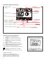
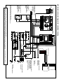
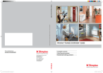
ZW 05 DCU Charge Control Set-Up
Terminals I1, I2
Control signal -2.85...-3.6V
Buttons for special
settings
S
KV
I1
I2
1
2
3
Dim plex
Multi function display
MODE
LL
ATM
LF
Ab
LZ
LFÜ
Terminal KV
Day switching
E5
AT W
E2
E4
Rotary switch
KU
KV
E3
Button
230V
L
50 Hz
N
4
Terminal LL
5
LF
LZ
KU
6A
SH
KV
Z1
Z2
W2
W1
6
7
8
9
10
11
12
13
14
15
power supply
Terminals W1/W2
External sensor
start of clock
Terminal LZ additional charge release
Terminal KU heating curve switching
Explanation of multi-function display items
LL:
LF:
Activated when LL terminal is activated
Activated when LF (charge release) terminal is
activated
LZ:
Activated when LZ (additional charging) terminal is
activated
KU: Activated when KU (characteristic curve switching)
terminal is activated
KV:
Activated in the daytime characteristic curve (KV
output)
ATM: Activated in external temperature averaging operation
(ATM (external temperature averaging) = JA (yes)
Abw: Activated in period of absence (Abw) mode
LFÜ: Activated when runtime detection monitor is activated
:
Weekly programme display “WoP = Ja” (weekly
programme = yes)
“LSU = JA” (charge synchronisation with timer = yes)
LED display operating mode:
If display is not lit – operating mode is active
Green light – technician menu display mode is active
Red light – technician menu setting mode is active
Briefly-lit orange light – software reset has occurred
8
ZW 05D C U
E - N r. :2 1 /0 3 0 1 ( 0 1 )
LL
Terminal LF release period
:
E10
E1
D C - Z e n tra ls te u e rg e rä t
2 VA
Terminals L, N
E15
Terminals Z1+, Z2Control signal 0.91...1.43V
Terminal KV
Day switching
Terminal SH relay output
charge contactor
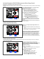
Activation Examples for ZW 05 DCU Microprocessor-Driven Charge Control
Backward or intermediate control with timer function
Standard installation with heating contactor or direct control of electric storage heaters (via charge control line) without heating
contactor.
“LF” (charge release) signal to LL (runtime) and LF
(charge release) terminals
S
KV
I1
I2
1
2
3
D im p lex
MODE
LL
AT M
LF
Abw
LZ
LFÜ
AT W
E5
No voltage at “LF” (charge release) terminal:
E2
E4
KU
KV
E3
E 15
E 10
E1
ZW 05 DC U
D C - Z e n t ra l s t e u e r g e rä t
2 VA
6A
50 HzLL LF LZ KU SH
L N
LL
LF
LZ
KU
SH
L
N
4
4
5
5
6
6
7
7
8
8
E - N r. : 2 1 / 0 3 0 1 ( 0 1 )
KV
Z1
Z2
W2 W1
KV
Z1
Z2
W2 W1
23 0 V
9
10
9
1
0
Voltage at “LF” (charge release) terminal:
Output of the weather-dependent and run-time
dependent control voltage (0.91 to 1.43 V)
Time function element activated (timer is running)
11
12
13
14
15
1
1 1
2 1
3 1
4 1
5
Safety overlap at 1.95 V control voltage
(charge suppression)
Runtime (LA) < locking duration SEH (lock):
Timer element is deactivated (timer stopped)
Runtime (LA) > locking duration SEH (lock):
Timer element activated (timer is running)
*For charge types with daytime charging periods and special LZ
(additional charging) release signals, the “LZ” terminal must be
activated
(Please observe the technical connection requirements of
the utility company).
Forward control without timer function
Standard installation with heating contactor
Remove LL-LF bridge and put bridges between L-LF
and LF-LZ
KV
I1
I2
1
2
3
S
D im p lex
MODE
LL
AT M
LF
Abw
LZ
LFÜ
AT W
E5
E4
E2
Output of the weather-dependent control voltage (0.91 1.43 V)
Time function element is not activated (timer is stopped)
Runtime display = LA (runtime) 0.00 hours
KU
KV
E3
E15
E1
E10
ZW 05DCU
D C - Z e n tra lst e u e r g e rä t
2 VA
50 HzLL LF LZ KU SH
6A
L N
LL
LF
LZ
KU
SH
230V
L
4
4
N
5
5
6
6
7
7
8
8
9
10
9
1
0
E - N r. : 2 1 /0 3 0 1 ( 0 1 )
KV
Z1
Z2
W2 W1
KV
Z1
Z2
W2 W1
11
12
13
14
15
1
1 1
2 1
3 1
4 1
5
When this type of activation is used in connection with an
underfloor storage heater, the runtime detection of the
charge control should be switched off (menu item SHC
(terminal output characteristic) = LF (charge release), LFU
(charge release detection) = UMD (circulation period)).
In the case of a breakdown, an additional temperature
limiter must be used to limit the storage layer temperature.
Forward control with timer function
Standard installation with heating contactor or direct control (via charge control) without heating contactor (only suitable for
systems with storage heaters)
S
KV
I1
I2
1
2
3
D im p le x
Laying LF (charge release) or SH (heating
contactor activation terminal) release signal from
utility company to LF terminal and bridging
between LF and LZ
M O D E
LL
ATM
LF
Abw
LZ
LFÜ
Voltage to “LF” terminal
E5
AT W
E2
E4
KU
KV
E3
E 15
E10
E1
ZW 05 D CU
D C - Z e n t r a ls t e u e r g e r ä t
2
V A
L N LL LFLZ KUSH
23 0V
L
50 H z
N
6A
LL
LF
LZ
KU
SH
4
5
6
7
8
9
1
0
4
5
6
7
8
9
10
E - N r. : 2 1 / 0 3 0 1 ( 0 1 )
KVZ1 Z2 W2W1
KV
Z1
Z2
W 2
W 1
1
1 1
2 1
3 1
4 1
5
11
12
13
14
15
Output of the weather-dependent control voltage (0.91 –
1.43 V)
Timer element activated (timer is running)
No voltage to “LF” terminal:
Safety overlap to 1.95 V control voltage
(charge suppression)
Runtime(LA) < locking duration (SEH):
Timer element deactivated (timer is stopped)
Runtime (LA) > locking duration (SEH):
Time element activated (timer is running)
9
Inside
External sensor
L
N
High tariff
power supply connection
(control circuit)
Example A
enabling signal
LF or LF+Z
(Z = additional release
period)
ATW
S
KV
1
I1
2
E5
I2
3
Z2 W2 W1
13 14 15
MODE
ZW 05DCU
E-Nr.:21/0301(01)
E2
E10
E4
KV Z1
11 12
DC-Zentralsteuergerät
E15
E1
ZW 05 DCU charge control unit
Dimplex
ATM
Abw
LL
LF
KU
KV
LF
E3
6A
LZ KU SH
8
9 10
LFÜ
LF
7
LZ
2 VA 230V 50Hz
LL
L N
4
5
6
LZ
Tariff time switch or
ripple control receiver
LF
Control of terminal LL,LF and LZ varies according to utility company.
Please observe the technical connection requirements of your utility company.
Switching from backward control to forward control
via control of terminals LF and LZ.
Example B
enabling signal
LF and LZ separate
Tariff time switch or
ripple control receiver
characteristic curve switching
Reduction contact to
Outside
KU
50
E-Nr.: 21/0303(01)
L N ZKU
-15
-30
0
E5 / %
30
15
GR05DC
A1A2 Z2 Z1
- +
- N
+ L
DC-Gruppensteuergerät
Dimplex
KUP / %
100
0
L
N
PE
Auxiliary relay
(please observe
instructions of your
utility company!)
L1
L2
L3
N
PE
Storage heaters
To the storage
heaters
To further
storage heaters
A2 A1 A2 A1
LH N N LE ~ ~ - + PE PE L- L- L1 L2 L3 N N N- NR SH
SH R
Room
controller
Charging/ heating
contactor
Low tariff power supply connection
(charging circuit)
High tariff power supply
(discharging circuit, habitation)
TA
(Central temperature reduction)
To
group control
In systems without group
control units, the control
signal (Z1, Z2) is switched
directly from the central
control unit to the storage
heater.
GR 05 DC group control unit
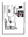
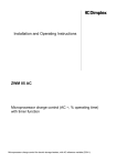
ZW 05 DCU connection diagram for electric storage heaters
10
LF
LL
LFÜ
Abw
ATM
KU
KV
LF
I1 I2
E10
Z1+
Z2-
W2
E2
W1
MODE
E-Nr.:21/0301(01)
ZW 05 D CU
E15
E5
Central control unit
KV
ATW
E4
E1
KV
DC-Zentralsteuergerät
E3
L N LL LF LZ KU SH
LZ
LF
Dimplex
Charge
controller
N
Z
T
I
í
AR 05DCU
LG1
77%
SH SH SH SH
L N F 1 2 3 4
Peripheral zone
heating
Underfloor
storage heating
Residual heat sensor
Mod
SH 4
SH 3
SH 2
SH 1
KV Z1+ Z2- TF TF1 TF2 TF3 TF4
/I2 /I1
ZW 05 DCU connection diagram for underfloor heating
Inside
External sensor
Outside
Reduction contact
(optional) for characteristic
curve switching
to KU terminal
N
L1
Enabling signal
(LF or LZ)
tariff time switch or
ripple control receiver
Example
Enabling signal LF and
LZ separate
tariff time switch or
ripple control receiver
Example B
The SH characteristic “SHC” in the menu of
the ZW 05 DCU central control unit must be set to “LF”.
Heating
circuit
contactor1
í
KV
Z1+/I2
Z2-/I1
TF
TF1
TF2
TF3
TF4
L1
L2
L3
N
PE
L1
Central control unit
with control signal
-2,85 ... -3,6V
KV/KU
Z1
Z2
High tariff
power supply connection
Power supply connection
(heating circuit)
Switching off the heating element
that includes the residual
,
heat
sensor necessitates
switching off all heating
elements of the same heating
circuit
To electric
storage heaters
Transmission of control signal
of any electric
storage heaters
-2,85 ... -3,6V
Main
contactor
AR 05 DCU charge controller
To further
heating circuits
Room temp.
controller
with floor
temperature limiter
N
PE
The ZW 05 DCU microprocessor-driven charge control has 2 separate control signal outputs.
The charge controllers for underfloor storage heating AR 05DCU or storage heaters can be connected to the Z1+, Z2- terminals (0.91 ... 1.43V). Charge controllers for underfloor
storage heaters with control signal -2.85 ... -3.6 V (e.g. Type AR 1741 ... AR 1744, RFV 351 DC ... RFV 354 DC) to terminals I1, I2 .
11
Outside
External sensor
Inside
Reduction contact for
characteristic curve switching
L
N
High tariff
power supply connection
(control circuit)
E4
ATW
S
Z1
12
KV
1
E10
I1
2
I2
3
E2
Z2 W2 W1
13 14 15
MODE
E-Nr.:21/0301(01)
ZW 05 DC U
E15
E5
ZW 05 DCU charge control unit
Dimplex
ATM
E1
KV
11
DC-Zentralsteuergerät
E3
6A
KU SH
9
10
Abw
LZ
8
LFÜ
LF
7
LL
230V 50 Hz
LL
L
N
4
5
6
LF
2 VA
LZ
KU
KV
LF
Tariff time switch or
ripple control receiver
Enabling signal
LF or LF+Z
(Z=additional release period)
L1
Auxiliary relay
(please observe utility
company instructions)
The SH terminal can be used to control a heating contactor or to control a contactor for
groups of heaters. Thus, e.g. electric storage heaters without control signal input
or non-system electric storage heaters can be controlled, dependent of weather
L2
L3
N
PE
Low tariff power supply connection
(charging circuit)
The SH output is switched (L potential) when a release is pending at the central control unit (LF terminal activated),
and when a set charge rate of > 0 % is calculated, dependent upon the outside temperature and the runtime.
The prerequisites for this are:
- Setting the central control unit to backward control (E3);
- The SH characteristic (SHC) in ZW 05 DCU must be set to LA.
- Activation (enabling signal) of the central control unit via the LF and LZ terminals
- For LZ activation see menu from FSU onwards
Charging/heating
contactor
To
storage
heaters
ZW 05 DCU connection diagram: External-temperature-dependent control via SH (heating contactor activation terminal) control
output (with SH characteristic SHC (terminal output characteristic) = LA (runtime))
12
Direct control via charge control line Z1+/Z2The ZW 05 DCU microprocessor-driven charge control can
be used for direct control of storage heaters with electric
charge controller via the charge control line (signal: 0.91 to
1.43 V DC).
For direct control via the charge control line Z1+/Z2-, the
network connection does not lead through the heating
contactor, but directly to the connection terminals of the
storage heater. L1, L2 and L3 terminals have a constant
voltage.
Activation for charge release is switched by the utility
company via the charge control. At the Z1+/Z2- terminals,
the weather-dependent and runtime-dependent control
voltage is only active with activation of “LF” (with LF or SH)
or “LZ” terminals.
For non-activated terminals “LF" or “LZ”, the central control
unit provides a control voltage of 1.95 V, thus locking the
charging of the storage heater.
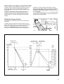
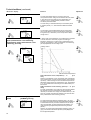
Setting the Charge Control
The charge control should only be set by an experienced
technician.
The ZW 05 DCU microprocessor-driven charge control is
preset as backward control for an 8-hour lower tariff release
period only. If adjustments to the technician menu are
necessary, configuration mode must be activated by
pushing the “Sondereinstellungen” (special settings) button.
Charge curve
Charge curve
Night time curve
Day time curve
Set heating
content in %
Effective
external temperature
13
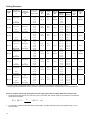
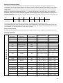
Setting Examples
Charge
type
Duration of
release period
tF
Duration of
External temp.
additional
θa acc. to
release period
DIN EN 12831
tZF
Between 9 p.m.
and 7 a.m.
8+0h
8h
Backwards
Between 9 p.m. Between 1 p.m.
and 7 a.m.
and 4 p.m.
Between 9 p.m.
and 7 a.m.
9+0h
100 %
E.g.
+ 15 °C
E.g.
15 %
7h
Secondary
- 12 °C
- 14 °C
- 16 °C
- 18 °C
- 10 °C
- 12 °C
E.g.
E.g.
-
- 14 °C
+ 15 °C
15 %
4h
Secondary
Between 12
p.m.
and 9 p.m.
2h
Secondary
-
and 6 a.m.
Between 12
p.m.
and 6 p.m.
10 + 6 h
10 h
Backward
- 10 °C
- 16 °C
- 18 °C
- 10 °C
- 12 °C
- 14 °C
- 16 °C
- 18 °C
- 10 °C
- 12 °C
- 14 °C
10 h
Backward
Between 8 p.m.
- 16 °C
- 18 °C
- 10 °C
- 12 °C
- 14 °C
- 16 °C
- 18 °C
- 10°C
- 12 °C
- 14 °C
- 16 °C
- 18 °C
effective
E.g.
15 %
9+2h
10 + 0 h
15 %
E.g.
+ 15 °C
2h
Secondary
9h
Backwards
Between 9 p.m. Between 1 p.m.
and 7 a.m.
and 4 p.m.
9h
Backward
Between 8 p.m.
and 6 a.m.
E.g.
+ 15 °C
100 %
8+7h
8h
Backwards
Between 9 p.m.
and 7 a.m.
E.g.
- 14 °C
E.g.
15 %
8+4h
8h
Spread
- 10 °C
- 12 °C
Characteristic curve adjuster
Full charge E1
Additional
Storage
charging
Underfloor
heating
E10
heating
devices
- 10 °C
Not
- 12 °C
E.g.
+ 15 °C
8+2h
8h
Backward
Charge
start
E2*
Base
charge
start
E15
6h
Secondary
- 14 °C
**
- 16 °C
- 18 °C
- 4 °C
- 6 °C
- 7 °C
- 9 °C
- 10 °C
0 °C
- 1 °C
- 3 °C
- 4 °C
- 5 °C
- 10 °C
- 12 °C
- 14 °C
- 16 °C
- 18 °C
- 10 °C
- 12 °C
- 14 °C
- 16 °C
- 18 °C
effective
Not
25 %
7h
4h
30 %
7h
30 %
- 10 °C
- 12 °C
- 14 °C
- 16 °C
- 18 °C
Not
effective
- 14 °C
**
8h
effective
- 10 °C
- 12 °C
- 14 °C
- 16 °C
- 18 °C
8h
25 %
**
100 %
E.g.
+ 15 °C
E.g.
15 %
100 %
E.g.
E.g.
Not
+ 15 °C
15 %
Effective
- 14 °C
Not
Not
- 16 °C
- 18 °C
- 10 °C
+ 1 °C
- 10 °C
+ 0 °C
- 1 °C
- 2 °C
- 4 °C
- 12 °C
- 14 °C
- 16 °C
- 18 °C
E.g.
15 %
7h
+ 4 °C
- 16 °C
- 18 °C
- 4 °C
- 6 °C
- 8 °C
- 10 °C
- 11 °C
- 10 °C
- 12 °C
E.g.
+ 15 °C
Minimum
base
E4
+ 3 °C
+ 3 °C
+ 1 °C
0 °C
- 10 °C
- 12 °C
- 16 °C
- 18 °C
- 12 °C
- 14 °C
- 16 °C
- 18 °C
Main
charging
period
E3
100 %
9h
Effective
9h
30 %
* Should the base charge start E15 be set to 0%, we recommend correcting the charge start to +20° C.
** Charge type without additional release periods in combination with underfloor storage heating is not recommended.
Notes for systems with storage heating devices and charge types with secondary additional release periods:
Should external temperatures vary from those given in this table, then the full charge E1 characteristic curve adjuster
should be set as follows:
E1
20 C
tF
tF
t ZF
* ( 20 C
e
)
For secondary, additional high-tariff release periods (tZF), activating the daytime skip (TAS (daytime skip) = E1) is
recommended.
14
Input Menu of the Microprocessor-Driven Charge Control for Technicians
If the forward button [▼] be held down for approx. 10 seconds, the unit will switch into the display mode (technician menu). In
the display mode menu for technicians, the LED display (green) is lit during display mode and the configuration settings can
be accessed via the "" und "" buttons. Changing the settings is not possible.
Should no button be pushed in the active display mode for a period of approx. 3 minutes, the unit automatically returns to the
operator mode after this time has elapsed. You can also exit the display mode by holding down the forward button [▼] for 10
seconds. The menu item selected via the rotary switch will be displayed.
Should the setting parameters in the technician menu need to be changed, then the configuration mode is activated by
pushing the “Special Settings” button.
In configuration mode, the LED display is lit (red) and the configuration settings can be accessed via the “” and “” buttons.
The flashing menu item can be changed via the "Plus" [+] and "Minus" [-] buttons. Changes will be made automatically with the
adjustment and saved upon exiting the configuration mode. By pushing the button “Sondereinstellungen” (special settings), or if
3 minutes have elapsed and no change has been made, the control unit returns back to the selected status display. Exception:
if the charge rate service function SEL % is activated, the display remains set on this menu item for 4 hours. The backlighting
of the display goes out after approx. 3 minutes.
Menu item / display
Comment
Adjustment
START Technician Menu
Full charge E1
[-25 ... 15°C]
The full charge E1 indicates the effective external temperature
(ATW) from which full charging on the charge controller is
determined via the charge control. (The setting depends upon
the charge type and the location of the system)
Main charging period E3
[0... 14 hours]
The main charging period E3 determines the runtime hour in
which the night-time characteristic curve reaches the weatherdependent set charge rate. Attention: do not set E3 higher than
the lower tariff release. For backward control:
E3 = tF
(release period) - 1 h
For spread control: E3 = tF (release period) - 0.5 h
For forward control: E3 = 0 h
(e.g. 8-hour lower tariff release and backward control E3 = 7 h)
Minimum base E4
[0 ... 100%]
For charge types with daytime charging periods, the minimum
base E4 determines the amount of residual heat base at the end
of the daytime characteristic curve.
Note: when setting the E4, please observe the tariff
requirements of the utility company. The E4 adjuster does not
function during simultaneously activated “LF” and “LZ” terminals
(forward control).
Daytime skip (TAS)
[E1 / NEIN (no) / -10...10°C]
Adjuster for automatic external temperature-dependent
suppression of daytime charging,
TAS (daytime skip) = E1:
Daytime charging, e.g. with higher
tariff release, suppressed to the full charge temperature set with
E1.
TAS (daytime skip) = NEIN (no):
Daytime skip is switched
off; daytime charging will carry on depending upon the
characteristic curve adjusters E10 and E4.
TAS (daytime skip) = ...°C
Daytime charging, e.g. at higher
tariff release, is suppressed to an adjustable effective external
temperature (-10 to 10°C).
Daytime switching (TU)
[6...14 hours]
Daytime switching (TU) determines the runtime point at which
the microprocessor-driven charge control switches from nighttime to daytime characteristic curve.
15
Technician Menu (continued)
Menu item / display
Lock (SEH)
Comment
Adjustment
[0...8 hours]
The lock (SEH) determines the moment at which the
microprocessor-driven charge control switches into lock status.
In lock status, the timing element runs independent of LL
(runtime) or LL/LF (charge release) activation until the
circulation period has ended.
The lock setting is calculated based upon the release period
tF (release period) - 2 h, and exceed the additional release
period.
Circulation period UMD
The circulation period (UMD) determines the runtime after
which a new daytime cycle can be activated by starting the
timing element (LL activation) of the microprocessor-driven
charge control.
Characteristic curve switching (KU)
[KUT (characteristic curve switching,
temperature) / KUP (characteristic curve
switching, percent)]
In active mode, the characteristic curve switching KU (activation
of the KU terminal or automatic program for lowering) is
followed by switching to one with a KUT (characteristic curve
switching, temperature) or KUP (characteristic curve switching,
percent) adjustable, second charge curve.
Heating content
Effective external temperature
KUT (characteristic curve, temperature) =… °C
[5 to
15°C]
With KUT (characteristic curve, temperature) and characteristic
curve switching (KU) in active mode (lowered or frost-protected
operation), a second charge curve is activated that provides an
adjustable charge start (KUT (characteristic curve, temperature)
in °C) via a parallel shift of the charge curve determined by E1,
E2 and E15.
KUP (characteristic curve switching, percent) = … %: [0 to
100%]
For KUP (characteristic curve switching, percent) and activated
KU terminals, a second characteristic curve (proportional
reduction) is activated. The charge curve determined by E1, E2
and E15 is thereby proportionally reduced to the value set with
KUP (characteristic curve switching, percent).
External temperature averaging
(ATM)
[JA/NEIN (yes/no)]
For active external temperature averaging (ATM = JA (yes)),
the daytime temperature average value (calculated according to
a mathematical formula) is used to determine the set charge
rate. (Compensation for larger temperature fluctuations, low
night-time and high daytime temperatures during transition
periods.)
Attention: for active external temperature averaging (ATM = Ja
(yes)), the effective external temperature (ATW) displayed is
the averaged temperature.
16
Technician Menu (continued)
Menu item / display
Comment
Adjustment
Type of external sensor
The control can be connected to an NTC-DIN sensor or to a
PTC sensor (700 Ohm at 20 °C). The automatically identified
sensor type is displayed. Correction of the external-temperature
measured value is possible [-10 to 10 °C].
Correction of the external sensor should only be carried out if
the location installation of the sensor is known and the
temperature of the sensor or wall (depending on the individual
installation) can be measured! External temperature averaging
must be switched off during measurement (ATM (external
temperature averaging) = NEIN (no)).
(For example: If the ATW (effective external temperature) is 4 °
too low compared to the measured value, then a corrected
value of “4 °C” should be set via the “+” button.)
Set charge rate (LAD)
[Display 0... 100%]
Display of the current set charge rate (LAD) in %, calculated by
the central control unit.
The interrelationship between the set charge rate and the
control voltage is as follows:
Set point charge rate Control voltage (UST)
LAD (charge)
Z1+/Z2I1/I2
Charge start 0%
1.43 V 1)
-3.60 V 2)
10%
1.38 V
-3.53 V
20%
1.33 V
-3.45 V
30%
1.27 V
-3.38 V
40%
1.22 V
-3.30 V
50%
1.17 V
-3.23 V
60%
1.12 V
-3.13 V
70%
1.07 V
-3.08 V
80%
1.01 V
-3.00 V
90%
0.96 V
-2.93 V
Full charge 100%
0.91 V
-2.85 V
Safety overlap for charge suppression (without LF (charge
release) or LZ (additional charging)) to:
1) 1.95 V
2) -4.35 V
Service function (SER)
Not possible
[NEIN/JA (no/yes)]
Switching to SER (service function) = JA (yes) provides the
option of targeted checking of a storage heating system by
selecting the service charge rate (SEL) in %.
- SEL (service charge rate) 0%
Provides a control signal from > 1.43 V or < -3.60 V. System or
units may not access the network.
- SEL (service charge rate) 1% to 100%
Output of a control signal corresponding to the LAD shown in
the table above. System or units can access the network when
set to 100% (Exception: system is fully charged).
The service function switches off automatically after a period of
4 hours or after exiting the menu item.
Control voltage at the terminals (UZ)
[Display]
Displays the calculated control voltage between the Z1+/Z2control terminals.
0.91 – 1.43 V: effective control voltage range during which
charging occurs
1.95 V: Charging is locked in the case of non-activated “LF”
(charge release) or “LZ” (additional charging) terminals
Not possible
17
Technician Menu (continued)
Menu item / display
Comment
Adjustment
Control voltage at the terminals (UI)[Display]
Displays the calculated control voltage between the I1/22
control terminals.
-2.85... -3.6 V: effective control voltage range within which
charging occurs
-4.35 V: Charging is locked in the case of non-activated “LF”
(charge release) or “LZ” (additional charging) terminals.
Not possible
* Release synchronisation with timer (FSU)
[NEIN/JA (no/yes)]
If FSU = JA (yes) is set, the release synchronisation with timer
is active. The runtime (LA) is then coupled with the real-time
timer and can no longer be changed.
Synchronisation takes place automatically at LFS (earliest start
of release). (The terminal functioning of LL (runtime), LF
(charge release) and LZ (additional charging), and the
functioning of the lock remain unchanged.)
If, in normal operation, the runtime (LA) is not LA = 00.00 hours
at the time of LFS (earliest start of release), it will be set to
00.00 hours.
Operating mode FSU (release synchronisation with timer) = JA
(yes) in connection with LSU (charge synchronisation with
timer) = JA (yes) can be used to release time-controlled
charging in periods without release signals or during very long
release periods. During time periods in which charging is not to
occur, a 100% operating time safety overlap will be released.
** Earliest start of release (LFS)
[00:00…23:59]
Earliest point in time at which accumulator charging can take
place when LF or LZ are activated.
(Starting point of runtime (LA) with LSU (charge synchronisation)
= JA (yes))
** Maximum duration of release (LFD)
[00:00 to 23:59 h]
Maximum duration of accumulator charging during the night-time
release period
** Earliest start of additional release (LZS)
[00:00 to 3:59]
Earliest point in time at which additional accumulator charging
can take place when LF or LZ are activated.
** Maximum additional release duration (LZD)
[00:00 to 3:59]
Maximum duration of charging during the additional release
period
** Synchronised charging via timer (LSU)
[NEIN/JA] (no/yes)
To activate synchronised charging secondary to the utility
company control signals via an integrated timer, the parameter
LSU = JA (yes) is to be programmed.
Active synchronised charging is indicated in the display by the
“Uhr” (timer) symbol
*
Only appears in the menu if the real-time timer is set to “JA” (yes) in the operator menu
**
Only appears in the menu if both the real-time timer is set to “JA” (yes) and menu item “FSU (release synchronisation with timer) = JA
(yes)” is set in the operator menu
18
Technician Menu (continued)
Menu item / display
Comment
Adjustment
SH terminal output characteristic (SHC) [LA/LF (runtime / charge release)]
SHC (terminal output characteristic) = LA (runtime): Runtimecontrolled contactor output for activation of a heating contactor or
activation of a contactor for groups of heaters.
SHC (terminal output characteristic) = LF (charge release):
According to DIN 44576, release period detection is additionally
required for underfloor storage heating. Charging is switched off as
soon as the totalled release periods (LF and LZ activation) within a
circulation period exceed the set value found under menu item
“LFU” (charge release detection). This is indicated in the display
with the "LFÜ" symbol. This is automatically reset after the start of
the next daytime cycle.
* Charge release detection (LFU) [6 ... UMD (circulation period)]
Maximum release period within a charging cycle (factory default)
LFU (charge release detection) = 15 hours; setting range 0… UMD
(circulation period)).
Note: The LFU (charge release detection) = UMD (circulation
period) setting switches off runtime detection. In connection with an
underfloor storage heater, the use of an additional, independently
switching ground temperature limiter is required for every heating
circuit.
* Initial underfloor heating cycle (FAZ)
[NEIN/JA (no/yes)]
If the initial underfloor heating cycle FAZ = JA (yes) is activated,
controlled initial heating of the insulating screed occurs over a
period of 168 hours (7 days). Hereby is charging gradually
increased.
Duration Remaining runtime Set charge rate
Day 1
168 to 145 hours 14%
Day 2
144 to 121 hours 29%
Day 3
120 to 97 hours 43%
Day 4
96 to 73 hours
57%
Day 5
72 to 49 hours
71%
Day 6
48 to 25 hours
86%
Day 7
24 to 0 hours
100%
The remaining runtime of the initial heating programme is displayed
in hours. After the 7th daytime cycle has elapsed, the basic
characteristic curve is returned to. After exiting the configuration
mode, the remaining runtime is displayed in place of runtime (LA).
** SH daytime heating contactor activation
output (SHT)
When operating the central control unit as backward control, the SH heating contactor
[NEIN/JA/AN% (no/yes/to%)]
activation terminal can be used to activate a heating contactor or to activate a
contactor for groups of heaters. Thus, for example, weather-dependent control of
storage heaters without control signal input is possible.
SHT (daytime heating contactor activation output) = NEIN (no): If the LF (charge
release) or LZ (additional charging) signal is connected, runtime is LA (runtime) TU
(daytime switching), and the calculated set charge rate is greater than 0%, the SH
terminal switches the L (charge) signal through.
SHT (daytime heating contactor activation output) = JA (yes): If the LF (charge
release) or LZ (additional charging) signal is connected and the calculated set charge
rate is greater than 0%, the SH terminal switches the L (charge) signal through.
SHT (daytime heating contactor activation output) = AN% (to%)
This menu item can only be selected if FSU (release synchronisation with timer)
= JA (yes) and >00:00 hours is set for LZD (additional release duration).
SHT (daytime heating contactor activation output) = AN% (to%) and LA (runtime)
TU (daytime switching)
If the LF (charge release) or LZ (additional charging) signal is connected and the
calculated set charge rate is greater than 0% (with a hysteresis of 4%), The SH
terminal switches the L (charge) signal through.
SHT (daytime heating contactor activation output) = AN and LA (runtime) > TU
(daytime switching)
The SH terminal switches the L (charge) signal through within a release period LZD
(additional release duration) (for the duration LZD x LAD (set charge rate) at the
LZB/100 point in time) if the LF (charge release) or LZ (additional charging) signal is
connected.
*
**
Only appears in the menu if the menu item "SHC (terminal output characteristic) = LF (charge release)" is set
Only appears in the menu if the menu item “SHC (terminal output characteristic) = LA (runtime)” is set
19
Technician Menu (continued)
Menu item / display
Program version T1
Program version T2
Segment test
Comment
Adjustment
[Display]
Program version µP 1
Not possible
Program version µP 2
Not possible
All display segments of the LC display are activated
Not possible
[Display]
[Display]
END of Technician Menu
Software reset
A software reset returns all settings to factory defaults.
1.
2.
3.
Configuration mode is activated by pushing the button “Sondereinstellungen” (special settings) ('“MODE” LED is lit red)
Press the forward button [▼] and backward button [▲] simultaneously for 60 seconds.
A brief change in colour of the LED display from red to orange indicates that the software reset was successful.
Start-Up
External temperature display (ATW – effective external temperature)
When the central control unit is connected to voltage, it takes approx. 1 minute for the external temperature to be correctly
calculated and displayed.
Setting the runtime (LA) when operating the charge control with timer function
The charge control features automatic runtime synchronisation. Upon leaving the factory, the runtime is set to 0.00 h. For
charge types with strictly night-time charging (e.g. 8 + 0 h), this setting need not be changed. The charge control synchronises
itself during the next lower tariff release. For charge types with additional charging periods during the day, the runtime must be
adjusted at start-up.
To do this, proceed as follows:
Subtract the starting point of the night-time (NT) release from 24 and add the current time to this result.
For example:
The start of the lower tariff release is 10 p.m.; the current time is 10:15 a.m.
24:00 h – 22:00 h + 10:15 h = 12:15 h
→ The runtime (LA) must be set to 12:15 p.m. (see operator menu)
Note: The runtime cannot be changed if the real-time timer is activated (Uhr (timer) = JA (yes)) in combination with FSU
(release synchronisation with timer) = JA (yes).
This automatic runtime synchronisation occurs automatically at the earliest start of release (LFS).
20
Start-up for underfloor heating
Initial heating of screed flooring according to the appropriate standards and guidelines, taking special specifications into
consideration, can only occur after the minimum wait time has expired. The simple initial start-up of underfloor storage heating
can be carried out via the automated underfloor initial heating cycle (menu item FAZ (initial underfloor heating cycle)) of the
charge control.
This function can be accessed in the configuration mode of the technician menu via the forward button [▼] or the backward
button [▲], and activated or deactivated using the “+” / “-” buttons. After activation, a set charge rate of 14% is specified,
starting with the first of the following charge release periods. The charge rate values of the following days are to be taken from
the table. If a value of 45 °C is set on the E6/AT (external temperature) adjustor when charge controllers are connected, and
the E8/KT (daytime) or E7/KN (night-time) correction adjuster is brought to the neutral position, then the following maximum set
temperatures will result:
Day
Set charge rate
Temperature
1
2
3
4
5
6
7
14%
23.5 °C
29%
27.1 °C
43%
30.7 °C
57%
34.3 °C
71%
37.9 °C
86%
41.4
100%
45.0 °C
The current characteristic curve is returned to after Day 7. The remaining runtime is displayed in hours.
The maximum permissible switch-off temperature (E6/AT (external temperature)) on the charge controller should be set after
consultation with the screed manufacturer or your screed flooring contractor. This adjustment should be carried out according
to the installation and operating instructions of the charge controller.
Storage heater start-up
For initial start-up of storage heaters, the following must be charged according to your installation and operating instructions.
Operator Menu
Start-Up Protocol
Operator menu
abbreviation
Operator menu
designation
Operator menu
factory default
LA/RES
Runtime
0 h/168 h
E5
Charge level
0%
E2
Charge start
15 °C
E15
Base charge start
15%
E10
Additional charging
85%
ATW
Effective external
temperature
External temperature
display
Uhr
Real-time timer
No
*TAE
Day setting
T1
*Anz
Display
AS
*Abw
Days of absence
0T
*Wop
Weekly programme
No
No □
Yes □
No □
Yes □
**MO Nor/MO KU
Monday
Nor
Nor □
KU □
Nor □
KU □
**DI Nor/DI KU
Tuesday
Nor
Nor □
KU □
Nor □
KU □
**MI Nor/MI KU
Wednesday
Nor
Nor □
KU □
Nor □
KU □
**DO Nor/DO KU
Thursday
Nor
Nor □
KU □
Nor □
KU □
**FR Nor/FR KU
Friday
Nor
Nor □
KU □
Nor □
KU □
**SA Nor/SA KU
Saturday
Nor
Nor □
KU □
Nor □
KU □
**SO Nor/SO KU
Sunday
Nor
Nor □
KU □
Nor □
KU □
Date of value setting:
No □
Yes □
AS □ Time □ AU □
Date of value change:
No □
Yes □
AS □ Time □ AU
□
* Only for setting “Uhr (timer) = JA (yes)”; ** Only for setting “WoP (weekly programme) = JA (yes)”
21
Technician Menu
Technician menu
abbreviation
Technician menu
designation
Technician menu
factory setting
E1
Full charge
- 12 °C
E3
Main charging
duration
7h
E4
Minimum charging
base
25%
TAS
Daytime skip
E1
TU
Daytime switching
10 h
SEH
Lock
6h
UMD
Circulation period
22 h
KUT/KUP
Characteristic curve
switching
(temperature/percent)
7 °C/ 40 %
ATM
External temperature
averaging
Yes
NTC/PTC
Type of external
sensor
NTC 0 °C
LAD
Set charge rate
Charge rate display
SER
Service charge rate
No
UZ
Control voltage at Z1
terminal
Display of control
voltage at terminal Z1
UI
Control voltage at I1
terminal
Display of control
voltage at terminal I1
FSU
Release
synchronisation with
timer
No
*LFS
Earliest start of
release
9:00 p.m.
*LFD
Maximum duration of
release
8h
*LZS
Earliest start of
release
9:00 p.m.
*LZD
Maximum additional
release duration
0h
*LSU
** Synchronised
charging with timer
SHC
Date of value setting:
No □
Yes □
Date of value change:
No □
Yes □
NTC __ °C PTC __ °C NTC __ °C PTC __ °C
No □
Yes □
No □
Yes □
No
No □
Yes □
No □
Yes □
SH terminal output
characteristic
LA
LA □
LF □
LA □
LF □
**LFU
Charge release
detection
15 h
**FAZ
Initial underfloor
heating cycle
No
No □
Yes □
No □
Yes □
**RES
Remaining runtime
(only for “FAZ Ja (yes)“)
Remaining runtime
display
(initial underfloor heating
cycle)
SHT
Daytime heating
contactor activation
output
No
PR1
Program part
version 1
Display
program version µP 1
PR2
Program part
version 2
Display
program version µP 2
See LA/RES
No □ Yes □ ON □
See LA/RES
No □
Yes □
Segment test
* Only for setting "FSU (release synchronisation with timer) Ja (yes)". ** Only for setting "SHC (terminal output characteristic)
LF (charge release)"
22
Correcting Basic Settings
The recommended basic settings are standard values that may have to be changed according to the type and location of the
building, the installation location of the external sensor, the release and additional release periods, the requirements of the
corresponding utility company and individual user preferences.
If changes are made, please note that corrections will only become apparent on the following day after the unit has been
charged. Changes to the charge control affect the entire heating system!
Changing the charge level
The basic charge level of the heating system can be changed via the E5 charge level adjuster (operator menu).
In order to increase charging, the E5 adjuster must be adjusted to the plus range.
Adjustment to the minus range leads to a decrease in charging.
Systems without daytime additional charging period
Fault description
Insufficient charging
Excess charging
External temperature
Adjuster corrections
E1
E2
E15
Colder than 0 °C
+ 3 °C
-
-
Between 0 °C and 10 °C
+ 2 °C
+ 2 °C
+ 5%
Warmer than 0 °C
-
+ 3 °C
+ 5%
Colder than 0 °C
- 2 °C
-
-
Between 0 °C and 10 °C
- 2 °C
- 2 °C
- 5%
Warmer than 0 °C
-
- 2 °C
- 5%
Systems with daytime additional charging period
Adjuster corrections
Fault description
External temperature
Colder than 0 °C
+ 3 °C
-
-
-
-
-
Insufficient charging
Between 0 °C and 10 °C
+ 2 °C
+ 2 °C
+5%
-
-
-
Warmer than 0 °C
-
+ 3 °C
+5%
-
-
-
Colder than 0 °C
- 2 °C
-
-
-
-
-
Between 0 °C and 10 °C
- 2 °C
- 2 °C
-5%
-
Warmer than 0 °C
-
- 2 °C
-5%
Warmer than E1 or TAS °C
(daytime skip °C)
-
-
-
Colder than E1 or TAS °C
(daytime skip °C)
-
-
Warmer than E1 or TAS °C
(daytime skip °C)
-
Colder than E1 or TAS °C
(daytime skip °C)
-
Excess charging
Insufficient or no daytime
charging
Daytime charging is too
high
E1
E2
E15
E4
E10
TAS
TAS °C
-
-
-
-
-
-
No
+ 3 °C
-
+ 10%
+ 10%
-
-
-
-
-
-
E1
- 3 °C
-
-
- 10%
- 10%
-
-
“+” → set value to increase the specified amount; “-” → set value to decrease the specified amount
Diagnostic Information
Thanks to its design and construction, the ZW 05 DCU microprocessor-driven charge control can be used in storage heating
systems with heating contactor, and for storage heating systems with direct control via the charge control line (Z1+/Z2-),
without a heating contactor. Thus, the weather-dependent and runtime-controlled control voltage is applied to the Z1+/Z2terminals of the central control unit only with activation of the LF (charge release) or LZ (additional charging) terminals. With a
non-activated LF or LZ terminal, the central control unit always releases a control voltage of 1.95 V to the Z1+/Z2- terminals (4.35 V to the I1/I2 terminals). Therefore, to check the control voltage signal it is necessary to activate the LF terminal (charge
release) or LZ (additional charging).
23
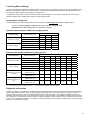
Table of measured values for checking the control voltages
To check the control signal of the central control unit, the following switching and/or settings are necessary:
3. Charge start adjuster E2 = 15 °C
1. Establish LF (charge release) activation
4. Full charge adjuster E1 = -12 °C
2. Set LA (runtime) adjuster to a value between E3 and
5. Base charge start adjuster E15 = 0%
daytime switching (TU) (= end of the nightime
characteristic curve)
Effective external temperature (ATW)
°C
20
16
12
8
5
0
-5
- 10
- 15
- 20
Control voltage to Z1+/Z2-
V
1.68
1.68
1.37
1.30
1.24
1.14
1.05
0.95
0.91
0.91
Control voltage to I1/I2
V
-3.60
-3.60
-3.52
-3.41
-3.32
-3.18
-3.04
-2.91
-2.85
-2.85
After measurements have been made, the original switching and setting of the microprocessor-driven charge control should be
re-established.
Testing the NTC or PTC external sensor
Set the rotary switch to the external temperature display (“ATW”). In the charge control display, the effective external
temperature is indicated that serves as the basis for calculating the control voltage.
In order to carry out a plausibility test (i.e. does the temperature measured via the external sensor correspond with the
displayed temperature ATM?), external temperature averaging (ATM) must be switched off during testing (ATM = Nein (no)). In
the case of active external temperature averaging (ATM = JA (yes)), it is not the current temperature of the external sensor that
is indicated in the display, but the averaged external temperature.
Temperature of external sensor
°C
20
16
12
8
4
0
-4
-8
- 12
- 16
- 20
NTC external sensor (series)
kΩ
2.43
2.85
3.36
3.98
4.73
5.64
6.76
8.14
9.84
11.96
14.62
PTC external sensor (Bauknecht
sensor)
Ω
700
692
684
676
668
660
652
644
636
628
620
Error messages
An error recognized by the central control unit is indicated with the corresponding fault code F… in the display;
the display will flash.
WFU
F001
WFK
F002
F003
:
Weather sensor interruption
Check weather sensor and replace if necessary
Weather sensor short-circuit
Check weather sensor and replace if necessary
Fault code from F003 onwards => unit error
Unit replacement necessary
In case of voltage cutoff
The central control unit has a power reserve of approx. 6 hours.
In the case of a voltage interruption exceeding approx. 6 hours, time of day must be set if the real-time timer is activated.
After-Sales Service
For customer service, please contact the Robert Bosch Hausgeräte GmbH.
To process your order, we require the production number E-no. and the production date (FD) of the unit.
This information can be found on the type plate.
Germany
Order service
Phone: 01801 22 33 55
Fax no. 01801 33 53 07
Spare parts ordering
Phone: 01801 33 53 55
Fax no. 01801 33 53 08
E-mail: [email protected]
Austria
Order service
Phone: 0810 240 260
Fax no. (01) 60575 51212
E-mail: [email protected]
Spare parts ordering
Phone: 0810 240 260
Fax no. (01) 60575 51212
E-mail: [email protected]
The Robert Bosch Hausgeräte GmbH is available for you 7 days a week, 24 hours a day!
Our emergency service team is also available on weekends and bank holidays!
Replacement part descriptions and replacement part orders from Robert Bosch Hausgeräte GmbH on the internet under:
http://www.dimplex.de/quickfinder
459238.66.59gb 03/07/A
Glen Dimplex Deutschland GmbH
Am Goldenen Feld 18
95326 Kulmbach, Germany
www.dimplex.de
24
Subject to technical changes
Phone: +49 (0)9221 709564
Fax:
+49 (0)9221 709589
E-mail: [email protected]