1
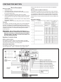
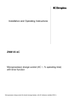
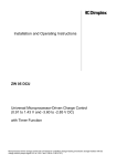
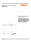
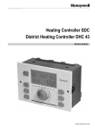
Installation and Operating Instructions DCP2010 VFMQ System Control Unit For installation, operation and maintenance, please observe these installation and operating instructions. This unit should only be installed and repaired by a qualified technician. Repairs which are improperly carried out can endanger the safety of the user and may damage the equipment. The installation and operating instructions must always be available to any technician working on the device for his/her information. We therefore request that these installation and operating instructions be passed on to the new tenant or owner should there be a change in occupancy. 7210900100REV00 Table of Contents HOMEOWNERS SECTION. . . . . . . . . . . . . . . . . . . . . . . . . . . . . . . . . . . . . . . . . . . . . . . . . . . . . . . . . . . 3 Application . . . . . . . . . . . . . . . . . . . . . . . . . . . . . . . . . . . . . . . . . . . . 3 Device Description . . . . . . . . . . . . . . . . . . . . . . . . . . . . . . . . . . . . . . . . 3 Appliance Controller . . . . . . . . . . . . . . . . . . . . . . . . . . . . . . . . . . . . . . . . . . . . . . . . . . . . . . . . . . . . . . . . . . . . 3 Storage Heater Controller . . . . . . . . . . . . . . . . . . . . . . . . . . . . . . . . . . . . . . . . . . . . . . . . . . . . . 4 Storage Heating User Settings. . . . . . . . . . . . . . . . . . . . . . . . . . . . . . . . . . . . . . . . . . . . . . . . . . . . . . . . . . . . 4 Systems using the Mid-Peak Period . . . . . . . . . . . . . . . . . . . . . . . . . . . . . . . . . . . . . . . . . . . . . . . . . . . . . . . 4 Systems NOT using the Mid-Peak Period. . . . . . . . . . . . . . . . . . . . . . . . . . . . . . . . . . . . . . . . . . . . . . . . . . . 4 Input Menu for Users . . . . . . . . . . . . . . . . . . . . . . . . . . . . . . . . . . . . . . . 5 Contractor SECTION . . . . . . . . . . . . . . . . . . . . . . . . . . . . . . . . . . . . . . . . . . . . . . . . . . . . . . . . . . . 7 Device Description . . . . . . . . . . . . . . . . . . . . . . . . . . . . . . . . . . . . . . . . 7 Scope of supply. . . . . . . . . . . . . . . . . . . . . . . . . . . . . . . . . . . . . . . . . . . . . . . . . . . . . . . . . . . . . . . . . . . . . . . . 7 Appliance Controller Setup. . . . . . . . . . . . . . . . . . . . . . . . . . . . . . . . . . . . . . . . . . . . . . . . . . . . . . . . . . . . . . . 7 Installation and Operating Instructions for Technicians . . . . . . . . . . . . . . . . . . . 9 Installing the Central Control Unit. . . . . . . . . . . . . . . . . . . . . . . . . . . . . . . . . . . . . . . . . . . . . . . . . . . . . . . . . 9 Installing the External Sensor . . . . . . . . . . . . . . . . . . . . . . . . . . . . . . . . . . . . . . . . . . . . . . . . . . . . . . . . . . . . 9 Wiring. . . . . . . . . . . . . . . . . . . . . . . . . . . . . . . . . . . . . . . . . . . . . . . . . . . . . . . . . . . . . . . . . . . . . . . . . . . . . . . . 9 Storage Heater Controller Set-Up. . . . . . . . . . . . . . . . . . . . . . . . . . . . . . . . . . . . . . . . . . . . . . . . . . . . . . . . . . 10 Activation Examples for Storage Heater Controller . . . . . . . . . . . . . . . . . . . . . . 11 Backward or spread control with timer function . . . . . . . . . . . . . . . . . . . . . . . . . . . . . . . . . . . . . . . . . . . . . 11 Direct Activation via Charge Control Line Z1/Z2 . . . . . . . . . . . . . . . . . . . . . . . . . . . . . . . . . . . . . . . . . . . . . 11 Setting the Charge Control. . . . . . . . . . . . . . . . . . . . . . . . . . . . . . . . . . . . . . . . . . . . . . . . . . . . . . . . . . . . . . . 11 Input Menu of the Storage Heater Controller for Technicians . . . . . . . . . . . . . . . . . 12 Software Reset . . . . . . . . . . . . . . . . . . . . . . . . . . . . . . . . . . . . . . . . . . 14 Start-Up . . . . . . . . . . . . . . . . . . . . . . . . . . . . . . . . . . . . . . . . . . . . . . 14 External temperature display (ATW – effective external temperature): . . . . . . . . . . . . . . . . . . . . . . . . . . . . . . 14 Setting the runtime (LA) when operating the charge control with timer function. . . . . . . . . . . . . . . . . . . 14 Start-up of storage heaters. . . . . . . . . . . . . . . . . . . . . . . . . . . . . . . . . . . . . . . . . . . . . . . . . . . . . . . . . . . . . . . 14 Start-Up Protocol. . . . . . . . . . . . . . . . . . . . . . . . . . . . . . . . . . . . . . . . . . . . . . . . . . . . . . . . . . . . . . . . . . . . . . . 14 Correcting Basic Settings. . . . . . . . . . . . . . . . . . . . . . . . . . . . . . . . . . . . . . . . . . . . . . . . . . . . . . . . . . . . . . . . 15 Systems NOT using the Mid-Peak Period. . . . . . . . . . . . . . . . . . . . . . . . . . . . . . . . . . . . . . . . . . . . . . . . . . . 15 Systems using the Mid-Peak Period . . . . . . . . . . . . . . . . . . . . . . . . . . . . . . . . . . . . . . . . . . . . . . . . . . . . . . . 15 Diagnostic Information . . . . . . . . . . . . . . . . . . . . . . . . . . . . . . . . . . . . . . 16 Testing the Total Control Resistance. . . . . . . . . . . . . . . . . . . . . . . . . . . . . . . . . . . . . . . . . . . . . . . . . . . . . . . 16 Testing the Triac. . . . . . . . . . . . . . . . . . . . . . . . . . . . . . . . . . . . . . . . . . . . . . . . . . . . . . . . . . . . . . . . . . . . . . . . 16 Testing the External Sensor. . . . . . . . . . . . . . . . . . . . . . . . . . . . . . . . . . . . . . . . . . . . . . . . . . . . . . . . . . . . . . 16 Error Display . . . . . . . . . . . . . . . . . . . . . . . . . . . . . . . . . . . . . . . . . . . . . . . . . . . . . . . . . . . . . . . . . . . . . . . . . . 16 In Case of Voltage Interruption. . . . . . . . . . . . . . . . . . . . . . . . . . . . . . . . . . . . . . . . . . . . . . . . . . . . . . . . . . . . 16 Technician Appendix. . . . . . . . . . . . . . . . . . . . . . . . . . . . . . . . . . . . . . . . . . . . . . . . . . . . . . . . . . . . 17 Setting Examples. . . . . . . . . . . . . . . . . . . . . . . . . . . . . . . . . . . . . . . . . . . . . . . . . . . . . . . . . . . . . . . . . . . . . . . 17 Additional Input Options for Storage Heater Controller . . . . . . . . . . . . . . . . . . . . . . . . . . . . . . . . . . . . . . . 18 Warranty. . . . . . . . . . . . . . . . . . . . . . . . . . . . . . . . . . . . . . . . . . . . . . . . . . . . . . . . . . . . . . . . . . . . . . 20 ! NOTE: Procedures and techniques that are considered important enough to emphasize. 2 CAUTION: Procedures and techniques which, if not carefully followed, will result in damage to the equipment. Warning: Procedures and techniques which, if not carefully followed, will expose the user to the risk of fire, serious injury, or death. www.dimplex.com HOMEOWNERS SECTION W arning: THIS CONTROL PANEL WILL ONLY DEACTIVATE ONE POLE OF A 208/240VAC SUPPLY. DO NOT SERVICE ANY APPLIANCE CONNECTED TO THIS CONTROLLER WITHOUT FIRST DE-ACTIVATING THE CIRCUIT AT YOUR MAIN SERVICE PANEL. FAILURE TO DO SO COULD RESULT IN ELECTRIC SHOCK OR DEATH. Warning: THIS CONTROL PANEL CONTAINS UP TO 5 SEPARATE CIRCUITS. ENSURE THAT ALL CIRCUITS HAVE BEEN DE-ACTIVATED AT THE SOURCE BEFORE OPENING THE ENCLOSURE. FAILURE TO DO SO COULD RESULT IN ELECTRIC SHOCK OR DEATH. The following sections will allow that user to understand the basics of the Dimplex control panel and make basic adjustments. For a full understanding of the product please read the entire manual. change and override some of the initial settings based upon their preferences. Device Description Appliance Controller (Figure 2) This appliance controller will connect and disconnect the power supply to the appliances that the user wishes to use within the time of use billing structure. The installer will connect the appliances and set up time of use clock to meet the local utilities rate structure. The user may then use the following controls to override the preset functions. CAUTION: Any use of the following controls will result in energy being consumed at higher electrical rates set out by your utility. Figure 2 Application Some electrical utility companies offer different electricity tariff rates based upon the time of day that the electricity is consumed; this is called “time of use” billing. Typically the utility will offer electricity at a lower rate when there is less demand. These periods of low demand are often described as Off-Peak times and periods of high demand are On-Peak times. Off-Peak times are usually overnight and On-Peak times are usually during a work day. In addition, some electrical utilities offer a Mid-Peak time during the day that has a rate between the Off-Peak and On-Peak. The actual times and rates of the various periods vary by utility, check with your local provider for rates and applicable times. This Dimplex control panel is designed to allow the user to take advantage of a time of use billing structure to save money on electricity consumption. The control panel consists of two separate controllers; one part of the panel controls household appliances (eg. water heaters, under floor, and other appliances) and the other part of the panel controls Dimplex Storage Heaters to their optimal charge level for the next day’s heating requirements. One Dimplex control panel can control up to 4 appliances (rated up to 240V and 30A each) and up to 30 Dimplex Storage Heaters. Your installation expert will ensure that the control panel will operate correctly for the applicable time of use billing structure. The following sections will allow the user to Figure 1 10.96 Before using these controls, ensure that the billing consequences are fully understood. • CIRCUIT ACTIVE (ON): Indicates that power is available to the appliance connected to this circuit. This light will be illuminated during Off-Peak periods, Mid-Peak periods (if selected) and Override periods. • OVERRIDE 1 HOUR: Indicates that this override option has been selected. This light will be illuminated when the “OVERRIDE” button has been depressed once. This feature allows the user to operate the selected circuit for 1 hour during a On-peak period. Once 1 hour has elapsed the control panel will return to normal operation. • OVERRIDE TO NEXT RATE PERIOD: Indicates that this override option has been selected. This light will be illuminated when the “OVERRIDE” button has been depressed twice. This feature allows the user to operate the selected circuit until the end of the current On-peak period. Once the end of the Onpeak period has arrived the control panel will return to normal operation. • OVERRIDE: This button allows the user to select two override modes for each circuit and return the circuit to automatic control. Starting from automatic control (no override lights illuminated): • Depress “OVERRIDE” once: Activates “OVERRIDE 1 HOUR” Depress “OVERRIDE” twice: Activates “OVERRIDE TO NEXT RATE PERIOD” 2.63 Depress “OVERRIDE” a third time: Returns to automatic control APPLIANCE CONTROLLER • 8.80 USE MID-PEAK RATE TO CHARGE: Indicates that the user has selected to use the pre-programed Mid-Peak schedule to operate this circuit. The control panel will supply power to the connected appliance during every Mid-Peak period. This feature can be selected or de-selected by depressing the “USE MID-PEAK RATE TO CHARGE” button. 3 HOMEOWNERS SECTION CAUTION: Ensure that the utility offers a Mid-Peak rate before using this feature. Storage Heater Controller The Storage Heater Controller functions to charge the connected storage heaters to the appropriate level for the next days’ heating needs. The Storage Heater Control uses advanced algorithms together with the outside temperature, the time of use structure and user settings to predict the amount of charge required. The installation expert will have set the controller to the factory recommended settings for the users’ specific installation. However, there are several user adjustable settings that allow the user to ensure that their personal comfort levels are always met. period. A lower number reduces operating costs but may reduce comfort by running low of heat by days’ end. Default is 85%. E15: During spring and fall, the minimum amount of heat (%) that the system will store. Increase if the system runs out of heat, decrease if the room feels too warm. Default is 15%. After initially setting up the Storage Heater there may be slight adjustments required to ensure that it is running at optimum performance. If the Storage Heater is not running correctly use the following charts to adjust the settings. CAUTION: The user must determine if the storage heater controller was installed to use the Mid-Peak period before any adjustments are made. Figure 3 Systems using the Mid-Peak Period The Storage Heater Control will save all settings in the event of a power failure. The Storage Heater Control also has an internal power source that will retain the time-clock settings for approximately 6 hours in the event of a power failure. If the timeclock is reset please refer to the installation part of this manual to set the time. Adjuster Corrections E2 E15 E10 Between 0 °C and 10 °C + 2° C + 5% Insufficient Charging Warmer than 0 °C + 3° C + 5% Between 0 °C and 10 °C - 2° C - 5% Excess Charging Warmer than 0 °C - 2° C - 5% Insufficient or No Colder than E1 or TAS + 10% Daytime Charging °C (daytime skip °C) Daytime Charging Colder than E1 or TAS - 10% is too High °C (daytime skip °C) “+” → increase set value by the specified amount “-” → decrease set value by the specified amount Fault description CAUTION: Changing any of the following settings will only result in a change to the next days’ heating requirements. Only change any setting in small increments as the effects of the change will only be realized the next day. Systems NOT using the Mid-Peak Period Fault description Storage Heating User Settings Settings Increasing and Decreasing Settings Forward Button (as Shown) or Backward Button to Change Display External temperature Insufficient charging Excess charging External temperature Adjuster Corrections E2 E15 Colder than 0 °C - - Between 0 °C and 10 °C + 2° C + 5% Warmer than 0 °C + 3° C + 5% Colder than 0 °C - - Between 0 °C and 10 °C - 2° C - 5% - 2° C - 5% Warmer than 0 °C “+” → increase set value by the specified amount “-” → decrease set value by the specified amount Ja = Yes Nien=No ATW: Displays the actual or averaged outdoor temperature. Day and 24-hour time display. MO=Monday FR=Friday DI=Tuesday SA=Saturday MI=Wednesday SO=Sunday DO=Thursday E1, E3, E4: These setting should only be adjusted by the installation expert. E2: The average outdoor temperature that the heaters will begin to store heat. Temperature is displayed in degrees Celcius. E5: Increase or decrease the average amount of heat storage to meet personal comfort levels by up to 30%. E10: Defines how much heat is stored (%) during Mid-Peak rate 4 www.dimplex.com HOMEOWNERS SECTION Input Menu for Users During normal operation, the unit is in operator mode. The “Mode” LED does not light up. The menu item shown in the display therefore depends on the position of the rotary selector switch as well as the setting of the ANZ (display) menu item. In operator mode, the individual menu items of the operator menu can be accessed with either the FORWARDS [▼] button or the BACKWARDS button [▲]. Individual menu items can also be directly accessed via the rotary selector switch. Adjusting the flashing setting parameters is possible via the "plus" [+] or "minus" [-] buttons. Changes will be made automatically with this adjustment. If 3 minutes should elapse and no adjustment has taken place, the control device automatically switches back to the selected display status and the changes are saved. Menu item / display Comment Adjustment Display of the week day and the time in “Timer function” mode (TIMER = Ja) and DIS = Timer / DIS = AS (automatic switching). Runtime - LA Display of the time that has elapsed since the start of the night-time charge release (start of charge release/LF) (Note: When release synchronisation is active (FSU (release synchronisation with timer) = Ja), adjustment of the runtime is blocked). Charge Level - E5 Changes to the basic charge level of all storage heating systems connected to the charge control. The set charge can be either proportionally raised or lowered by up to 30%, according to need. The change to the charge level should only be made gradually, since the effect of these changes will only become apparent after the unit has been charged. Charge Start - E2 Specifies the effective external temperature (ATW) at which storage cylinder charging should begin. (The higher the selected setting, the earlier charging will start and the higher the set charge amount at the same effective external temperature / ATW). Base Charge Start - E15 Specifies the minimum charging base which comes into effect when the effective external temperature set via E2 is undershot. Recommended setting: Insufficient charging in the transition period: raise E15 by 5% to 10%. Excess charging in the transition period: lower E15 by 5%. Additional Charging (Daytime Charging) - E10 Reduction or increase of an available daytime charging E10 = 0% means no charging in the afternoon, independent of the effective external temperature. ! NOTE: In the event that the daytime charging via the TAS (daytime skip) adjuster (TAS = E1 or TAS = TE; only accessible to technicians) is generally disabled at higher effective external temperatures, then the E10 adjuster is ineffective above these temperatures. Effective External Temperature (ATW) Display of the effective temperature at the external sensor location (at ATM (external temperature averaging) = 1: ATW (effective external temperature) corresponds to the averaged temperature at ATM (external temperature averaging) = 0: ATW corresponds to current temperature) Real-Time Timer Not Possible The Storage Heater Controller is equipped with a real-time function / weekly programme (TIMER = Ja). This can be utilized either strictly as additional information or for automatic charge lowering during longer periods of absence and/or according to the weekly programme. This offers the additional possibility, in connection with the FSU (release synchronisation with timer) = Ja function, to release or individually conceal charging independent of the time in areas without release signal in a time-controlled way. 5 HOMEOWNERS SECTION Operator Menu (continued) Menu item / display Comment Adjustment Real-Time Timer Continued ! NOTE: This can no longer be switched off after the real-time timer has been activated! Extended runtime function (real-time function) is activated Setting the Time Setting the current time Weekday Setting the current day of the week: T1 = Monday T5 = Friday T2 = Tuesday T6 = Saturday T3 = Wednesday T7 = Sunday T4 = Thursday Display Selection of desired display mode in normal operation DIS = AS (switch position indicator): according to the position of the rotary selector switch DIS = Timer: displays the time and day of the week DIS = AU (switch position indicator, timer): automatic switching of display between rotary selector switch position and time/day Days of Absence For the duration of the days selected (between 1 and 30), the KU (heating curve switching) is activated according to the KUT (heating curve switching, temperature) or KUP (heating curve switching, percent) setting parameters. After the period of absence has elapsed, the normal charging curve is reactivated. Weekly Programme Depending on cyclic user preferences, a mode between normal and lowered charging can be selected via the weekly programme. The active weekly programme is denoted in the display by the “Wochenprogram” (weekly programme) symbol (WeP). Weekday When WeP = Ja, each day of the week (Mo – Su) can be set to the appropriate heating curve (Normal or lowered charging). Nor: Normal charging KU (heating curve switching): from 8:00 pm of the previous day lowered charging (KU) activated. End of Operator Menu Changing to the technicians’ menu in the display mode. When the FORWARD button [▼] is held down for approx. 10 seconds, the device will switch to the display mode (menu for technicians). The LED display (green) lights up in display mode, and the configuration settings can be accessed via the “” and “” buttons. Changing the settings is not possible. Should no button be pushed in the active display mode for a period of approx. 3 minutes, the unit automatically returns to operator mode after this time has elapsed. The display mode can also be ended by holding down the FORWARD button [▼] for 10 seconds. The menu item selected via the rotary selector switch will be displayed. 6 www.dimplex.com Contractor SECTION Scope of supply • • • • • • • Device Description 208/240VAC, 60Hz 4 x terminals rated to a maximum of 240V, 30A 24V terminal and return, to power a dry contact that indicates the current electrical rate. A dipswitch to select/invert the logic of the dry contact. A set of 3 dipswitches to set the number of hours from the start of the peak rate to the start of the midday reduced rate period, 1-8 hours. A set of 3 dipswitches to set the duration of the midday reduced rate period, 1-8 hours. A dipswitch to select the relay delay mode (random or stepped). that the user prefers for the 4 circuits connected to the appliance controller. Mid-Peak Offset and Mid-Peak Duration The Appliance Controller will use its internal timer to allow selected circuits to be activated during the Mid-Peak period defined by switch 1-6. Switches 1-3 define the time, in hours, between the end of the Off-Peak period and the start of the Mid-Peak period. Switches 4-6 define the time, in hours, between the start and end of the Mid-Peak period. DIP Switch Settings Function The appliance controller will supply power the connected appliance during the Off-Peak periods and Mid-Peak periods (if selected by the user). The appliance controller will provide power based on the settings input with the DIP switch selectors located on the appliance controller circuit board. To access these settings the enclosure must be opened. Warning: THIS CONTROL PANEL CONTAINS UP TO 5 SEPARATE CIRCUITS. ENSURE THAT ALL CIRCUITS HAVE BEEN DE-ACTIVATED AT THE SOURCE BEFORE OPENING THE ENCLOSURE. FAILURE TO DO SO COULD RESULT IN ELECTRIC SHOCK OR DEATH Appliance Controller Setup External Switch Indicator The Appliance controller relies on an external switch to indicate the current rate period. Switch 8 selects the logic that the external switch will use to indicate the current rate period. Relay Startup Delay Pattern The Appliance Controller will not allow all of the circuits to become active simultaneously. Switch 7 selects the type of delay pattern Figure 4 7 Contractor SECTION Storage Heater Controller Central Control Unit and Charge Controller Operation The Storage Heater Controller controls the charging of storage heating devices depending on the external temperature, and controller set points and signals. The Storage Heater Controller uses an external sensor, which is installed in the brickwork of the house, to measure the weather conditions and the building inertia. Those values are combined as a reference variable, which is used with the various settings and runtimes, from the signals from the control terminals, to control the central control units output (charge rates = operating time signal to Z1/Z2). Technical Device Information Connection voltage 1/N/ 208/240V AC ~ 50/60 Hz Power consumption Approx. 2 VA Maximum load 300 W Switching capacity of safety output 6A, 230V ~ Device fuse Class G fuse insert F2 according to DIN 41660 (1.6A T) Power reserve Approx. 6 hours (runtime and clock) Ambient temperature Between 0 °C and 50 °C Protection class II according to installation (see section “Installation”) Dimensions See dimension drawing Weight Approx. 320g External sensor Sensor type NTC sensor according to DIN EN 50350 in insulated casing Connection cable 2m long (extendable up to a maximum of 30 m) Protection class II according to DIN EN 60730-1 Degree of protection IP54 according to DIN 40050 Dimensions See dimension drawing (Figure 5) The heat storage capacity of the entire heating system can be raised or lowered on the charge control. Figure 5 The charge controller that is built into the storage heater is an electronic-thermomechanical ON/OFF controller. The controller’s set point is determined by the operating time signal (on device terminals A1~/A2~) and by the intensity actuator (change selector knob on the storage heater). The actual value of charging in all storage heaters is determined via a residual heat sensor that measures the core temperature. The charge controller compares the set point with the actual value and calculates the level of charging required based on the difference between the two values. Power switching in the storage heater is thus controlled by the charge controller. Setting the intensity actuator on the storage heater (Charge Selector Knob) In automatic operation, the intensity actuator on the storage heater is set at the right-hand stop (factory setting), i.e. the storage heater charges at the value specified by the Storage Heater Controller. In areas which always have reduced heating requirements, e.g. bedrooms, charging of the storage heater can be reduced and the storage heater adjusted, by turning the charge selector knob to the left. With the knob at the left hand stop, no charging takes place. During automatic operation, operating errors and unintentional re-setting can be prevented by removing the control button from the storage heaters intensity actuator and covering it with the closing cap. If the storage heater is not necessary in the summer months (or even on the cooler summer nights), we recommend taking the entire heating system out of operation. For more information, consult your authorized electrician and your local utility company’s technical connection requirements. Figure 6 Figure 7 10 12 50 mm Dimensioning of Fuse 8 www.dimplex.com Contractor SECTION Installation and Operating Instructions for Technicians Installing the Central Control Unit Installation must only be carried out by a technician authorized by the respective utility company. The regulations of the local utility company, as well as the relevant electrical standards regulations are to be observed. The DCP2010 unit should be installed as close to the distribution panel as possible. Dimensions of the DCP2010 are 12” wide x 9 1/4” high x 4” deep with a NEMA 1 indoor panel for surface mounting. Installing the External Sensor The external sensor is to be installed at least 2m (6.5 feet) above the floor, preferably in the outer brickwork, see diagram below. The sensor should not be exposed to direct sunlight. Heat sources (e.g. ventilation shafts or tilted windows) must not influence the sensor and thus affect the Storage Heater Controller. Please observe the following: • • The external sensor must be embedded in the mortar The cable feedthrough must be carefully protected with thermal insulation material. The external sensor has a 2m (6.5’) long connection cable, which can be extended to a maximum of 30m (98’) using an installation lead #16/2 wire. Wiring Some terminals in the Charge Control Panel will not be used in a typical installation. Their functions are outlined in the Technical Appendix. The Charge Control Panel requires a minimum 15A 208/240VAC circuit to operate the Appliance Controller and the Storage Heater Controller. Preferably, this is a dedicated circuit as it will draw power during all rate periods (On-peak, Off-peak, and Mid-peak). Properly sized 2-conductor wire should be strain relieved and connected to the terminals marked L1 and L2 to supply the Charge Control Panel. Rate Indication The Appliance Controller determines the current rate period by the “Rate Signal” terminals. One terminal supplies a 24VAC signal, while the other terminal is set to detect a 24VAC signal. An external device is required to either block or pass the 24VAC signal. Dip switch 8, described in the Device Description section determines how the Charge Control Panel interprets the 24VAC signal. Properly sized 2-conductor wire should be strain relieved and connected to the “Rate Signal” terminals. Care should be taken to separate the low voltage wiring from the high voltage wiring as dictated by the relevant electrical code. Appliance Controller The Appliance Controller can operate up to 4 loads. Each load can be any resistive load rated up to 208/240VAC 30A. Each circuit is identified by a letter (circuit A = A1, A2, and A3). Each appliance connected to the Charge Control Panel should be on a dedicated circuit and have proper over current protection at the service panel. Properly sized 2-conductor wire should be strain relieved and connected to the terminals marked 1, 2 and 3. The appliance controller will operate to open one pole of the circuit to de-activate the appliance. The second pole is passed through the terminals at position 3. Storage Heater Controller The Storage Heater Controller has been connected to the Charge Figure 8 9 Contractor SECTION Control Panel to supply the correct voltage and control signals by the manufacturer. The installer must connect the control lines for the VFMQ storage heaters and the outdoor temperature sensor. The outdoor temperature sensor is a low voltage device connected to terminals W1 and W2. Properly sized 2-conductor wire should be strain relieved and connected to the W1, and W2 terminals. Care should be taken to separate the low voltage wiring from the high voltage wiring as dictated by the relevant electrical code. The storage heater control lines are 208/240VAC control lines that must be run separately to the supply lines to the VFMQ storage heaters. Properly sized 2-conductor wire should be strain relieved and connected to the terminals marked Z1 and Z2 to control the charging of the VFMQ storage heaters. The connections at terminals L and N should not be interchanged The LL (runtime), LF (charge release), LZ (additional charging) and KU (heating curve switching) pilot wires must be connected in phase with L (charging) Should a phase be connected to terminal W1, W2, Z1 or Z2 due to a mistake in the wiring, the unit will be destroyed. Calculating the Control Output • • • The maximum control output of the Storage Heater Controller charge control is 300 W. The control output of the heating system depends on the device type and number of devices. It can be calculated by adding the control outputs of all storage heaters. LF: Activated when LF (charge release) terminal is activated LZ: Activated when LZ (runtime) terminal is activated KU: Activated when KU (heating curve switching) terminal is activated ED: Activated when the control signal is output ATM: Activated in external temperature averaging operation (ATM (external temperature averaging) = Ja) Abw: Activated in period of absence (Abw) mode SUT:Activated when the control signal is suppressed in the daytime characteristic curve D: Activated in direct activation mode SUS: Activated when the control signal is suppressed and the effective external temperature (ATW) is higher than the value set for E2 : Weekly programme display “WeP=Ja” :“LSU (charge synchronisation with timer) = Ja LED operating mode display: If display is: Not lit – operator mode is active Green light – technician menu display mode is active Red light – technician menu setting mode is active Orange light (brief) – software has been reset Figure 10 The following table shows the control outputs of selected storage heater types. Device type Control output per device VFMQ 10 Watts Storage Heater Controller Set-Up Explanation of multi-function display items LL: Activated when LL terminal is activated Figure 9 10 www.dimplex.com Activation Examples for Storage Heater Controller Backward or spread control with timer function Standard installation with heating contactor or direct activation (via charge control) without heating contactor Release signal (LF) at terminals LL and LF Figure 11 Voltage at “LF” (charge release) terminal: • Output of the weather-dependent and runtime-dependent operating time control signal • Timer element activated (timer is running) No voltage at “LF” (charge release) terminal: • Runtime (LA) < locking duration (SEH): Timer element deactivated (timer is stopped). • Runtime (LA) > locking duration (SEH): Timer element activated (timer is running). Output of the weather-dependent and runtime-dependent operating time control signal. • When direct activation mode is activated: Safety overlap to 100% operating time (= charge suppression) *For charge types with daytime charging periods and special LZ (additional charging) release signals, the “LZ” terminal must be activated (Please observe the technical connection requirements of the utility company). Direct Activation via Charge Control Line Z1/Z2 Setting the Charge Control The Storage Heater Controller can be used for direct activation of VFDi, VFD, FSD, VNDi, VTDi and VKD storage heaters with electronic charge control via the charge control line. The charge control must only be set by an experienced technician. For direct activation via the Z1/Z2 charge control line, the network connection does not lead through the heating contactor but rather directly to the connection terminals of the storage heater. A constant voltage is connected to terminals L1, L2 and L3. Acivation for charge release is switched by the utility company via the central control unit. At terminals Z1/Z2, the weather-dependent and runtime-dependent control voltage is only active when “LF” or “LZ” is not activated, the central control unit provides 100% operating time signal (constant voltage), thus blocking the charging of the storage heater. For direct activation, the “Digital System” adjuster must be programmed to “D=Ja” The Storage Heater Controller is preset as a backward control for an 8-hour lower tariff-only release period. If adjustments to the technician menu are necessary, configuration mode must be activated by pushing the “Special settings” button. Figure 12 Figure 13 11 Input Menu of the Storage Heater Controller for Technicians When the FORWARD button [▼] is held down for approx. 10 seconds, the device will switch to display mode (menu for technicians). In this display mode, the LED display (green) lights up and the configuration settings can be accessed via the “” and “” buttons. Changing the settings is not possible. Should no button be pushed in the active display mode for a period of approx. 3 minutes, the unit automatically returns to operator mode after this time has elapsed. The display mode can also be ended by holding down the FORWARD button [▼] for 10 seconds and the menu item selected via the rotary selector switch will be displayed. Should the setting parameters in the technician menu need to be changed, then the configuration mode is activated by pushing the “Special settings” button. In configuration mode, the LED display lights up (red) and the configuration settings can be accessed via the “" and "" buttons. The flashing menu items can be changed via the "Plus" [+] and "Minus" [-] buttons. Changes will be made automatically with the adjustment and saved upon exiting the configuration mode. By pushing the “Special settings,” button, again, or if 3 minutes have elapsed and no change has been made, the control unit returns to the selected display status. Exception: if the charge rate service function SEL % is activated, the display remains set on this menu item for 4 hours. The backlighting of the display goes out after approx. 3 minutes. START Technician Menu Menu Item/Display Full charge E1 [-25 ... 15°C] Main charging period E3 [0 ... 14 hours] Minimum base E4 Daytime skip (TAS) [0 ... 100%] [E1/NO/-10..10°C] Daytime switching (TU) [6 ... 14 hours] Lock (SEH) [0 ... 8 hours] Comment Adjustment The full charge (E1) indicates the effective external temperature (ATW), starting at which the charge control specifies full charging by the charge controller. (The setting depends on the charge type and the location of the system) The main charging period (E3) determines the runtime hour in which the night-time characteristic curve reaches the weatherdependent set charge rate. Note: Do not set E3 higher than the lower tariff release. For backward control: E3 = tF - 1 h For spread control: E3 = tF - 0.5 For forward control: E3 = 0 h (e.g. 8-hour lower tariff release and backward control E3 = 7 h) For charge types with daytime charging periods, the minimum base (E4) determines the height of the residual heat base at the end of the daytime characteristic curve. Note: When setting E4, please observe the tariff requirements of the utility company. The E4 adjuster does not function during simultaneously activated “LF” and “LZ” terminals (forward control). Adjuster for automatic external temperature-dependent suppression of daytime charging, • TAS (daytime skip) = E1: Daytime charging, e.g. at higher tariff release, suppressed until the full-charge temperature set with E1 is reached. • TAS (daytime skip) = NO: Daytime skip is switched off; daytime charging will carry on depending on the characteristic curve adjuster. E10 and E4. • TAS (daytime skip) = ..°C Daytime charging, e.g. at higher tariff release, is suppressed until an adjustable effective external temperature (- 10 … 10°C) is reached. Daytime switching (TU) determines the runtime point at which the Storage Heater Controller switches from the night-time to the daytime characteristic curve. The lock (SEH) determines the moment at which the Storage Heater Controller switches into lock status. In lock status, the timing element runs independent of LL (runtime) or LL/LF (charge release) activation until the circulation period has ended. The lock setting is calculated based on the release period tF (release period) - 2 h, and should exceed the additional release period. 12 www.dimplex.com Input Menu of the Storage Heater Controller for Technicians Menu item / display Comment Adjustment Circulation period UMD [8 ... 23 hours] Heating curve switching (KU)[KUT (heating curve switching, temperature) / KUP (heating curve switching, percent)] The circulation period (UMD) determines the runtime after which a new daytime cycle can be activated by starting the timer element (LL activation) of the Storage Heater Controller. In active mode, the heating curve switching KU (activation of the KU terminal or automatic program for lowering) is followed by switching to one with a KUT (heating curve switching, temperature) or KUP (heating curve switching, percent) adjustable, second charge curve. Heat content Effective external temperature KUT (characteristic curve, temperature) =… °C [5 ... to 15°C] With KUT (heating curve switching, temperature) and heating curve switching (KU) in active mode (lower or frost protection operation), a second charge curve is activated which provides an adjustable charge start (KUT (characteristic curve, temperature) in °C) via a parallel shift of the charge curve determined by E1, E2 and E15. KUP (heating curve switching, percent) = … %: [0 ... 100%] For KUP (heating curve switching, percent) and activated KU terminals, a second characteristic curve (proportional reduction) is activated. The charge curve determined by E1, E2 and E15 is thereby proportionally reduced to the value set with KUP (heating curve switching, percent). External temperature averaging (ATM) [Ja/Nein] For active external temperature averaging (ATM = Ja), the daytime temperature average value (calculated according to a mathematical formula) is used to determine the set charge rate. (Compensation for larger temperature fluctuations, low night-time and high daytime temperatures during transition periods.) Note: For active external temperature averaging (ATM = Ja), the effective external temperature (ATW) displayed is the averaged temperature. 13 Input Menu of the Storage Heater Controller for Technicians Software Reset A software reset returns all settings to factory defaults. 1. Configuration mode is activated by pushing the “Special settings” button (“MODE” LED is lit red) 2. Press and hold the FORWARD (▼) and BACKWARD (▲) buttons simultaneously for approx. 60 seconds. 3. A brief change in colour of the LED display from red to orange indicates that the software reset was successful. Start-Up External temperature display (ATW – effective external temperature): When the central control unit is connected to the power supply, it takes approx. 1 minute for the external temperature to be correctly measured and displayed. Setting the runtime (LA) when operating the charge control with timer function The charge control features automatic runtime synchronisation. Upon leaving the factory, the runtime is set to 0.00 h. For charge types with night-time-only charging (e.g. 8 + 0 h), this setting does not need to be changed. The charge control synchronises itself during the next lower-tariff release. For charge types with additional daytime charging periods, the runtime must be set during start-up. The following procedure is recommended: Subtract the starting point of the night-time (NT) release from 24 and add the current time to this result. Example: The start of the lower tariff release is 10 p.m.; the current time is 10:15 a.m. 24:00 h – 22:00 h + 10:15 h = 12:15 h → The runtime (LA) must be set to 12:15 p.m. (see operator menu) Note: The runtime cannot be changed with an active real-time timer (Timer = Ja) in combination with FSU (release synchronisation with timer) = Ja. This automatic runtime synchronisation occurs automatically at the earliest start of release (LFS). Start-up of storage heaters For initial start-up of storage heaters, these must be charged according to your installation and operating instructions. Operator Menu Start-Up Protocol 14 Operator menu abbreviation LA E5 E2 E15 E10 Operator menu Operator menu factory Date of value setting: designation default Runtime 0h Charge level 0% Charge start 15° C Base charge start 15 % Additional charging 85 % Effective external External temperature ATW temperature display Timer Real-time timer Nein Nein □ Ja □ *TAE Day setting T1 *Dis Display AS AS □ Timer □ AU □ *Abw Days of absence 0T *WeP Weekly programme Nein Nein □ Ja □ **MO Nein/MO Ja Monday Nein Nein □ Ja □ **DI Nein/DI Ja Tuesday Nein Nein □ Ja □ **MI Nein/MI Ja Wednesday Nein Nein □ Ja □ **DO Nein/DO Ja Thursday Nein Nein □ Ja □ **FR Nein/FR Ja Friday Nein Nein □ Ja □ **SA Nein/SA Ja Saturday Nein Nein □ Ja □ **SO Nein/SO Ja Sunday Nein Nein □ Ja □ * Only for setting “Timer = Ja”; ** Only for setting “WeP (weekly programme) = Ja” Date of value change: Nein □ Ja □ AS □ Timer □ AU □ Nein □ Nein □ Nein □ Nein □ Nein □ Nein □ Nein □ Nein □ Ja □ Ja □ Ja □ Ja □ Ja □ Ja □ Ja □ Ja □ www.dimplex.com Technician Menu Input Menu of the Storage Heater Controller for Technicians Technician menu abbreviation E1 E3 E4 TAS TU SEH Technician menu designation Full charge Main charging duration Minimum charging base Daytime skip Daytime switching Lock Technician menu factory setting - 12° C 7h 25 % E1 10 h 6h Date of value setting: UMD KUT/KUP Circulation period 22 h Heating curve switching 7 °C/ 40% External temperature ATM Ja averaging * Only for setting “FSU (release synchronisation with timer) = Ja” Date of value change: E1 □ Nein □ °C __ E1 □ Nein □ °C __ KUT __°C KUP __% KUT __°C KUP __% Ja □ Nein □ Ja □ Nein □ Correcting Basic Settings The recommended basic settings are standard values that may have to be changed according to: the type and location of the building, the installation location of the external sensor, the release and additional release periods, the utility company’s technical connection requirements and individual user preferences. If changes are made to the settings, please note that corrections will only become apparent on the following day after the unit has been charged. Changes to the charge control affect the entire heating system! Making Basic Changes to the Charge Level The basic charge level of the heating system can be changed via the E5 charge level adjuster (operator menu) In order to increase charging, the E5 adjuster must be adjusted to the plus range. Adjustment to the minus range leads to a decrease in charging. Systems NOT using the Mid-Peak Period Fault description Insufficient charging Excess charging External temperature Adjuster corrections E1 E2 E15 Colder than 0 °C + 3° C - - Between 0 °C and 10 °C + 2° C + 2° C + 5% Warmer than 0 °C - + 3° C + 5% Colder than 0 °C - 2° C - - Between 0 °C and 10 °C - 2° C - 2° C - 5% Warmer than 0 °C - - 2° C - 5% Systems using the Mid-Peak Period Fault description External temperature Colder than 0 °C Between 0 °C and 10 °C Insufficient charging Warmer than 0 °C Colder than 0 °C Excess charging Between 0 °C and 10 °C Warmer than 0 °C Warmer than E1 or TAS °C (daytime skip °C) Insufficient or No daytime charging Colder than E1 or TAS °C (daytime skip °C) Warmer than E1 or TAS °C (daytime skip °C) Daytime charging is too high Colder than E1 or TAS °C (daytime skip °C) “+” → increase set value by the specified amount “-” → decrease set value by the specified amount Adjuster corrections E15 E4 E10 + 5% + 5% - 5% - 5% - E1 + 3° C + 2° C - 2° C - 2° C - E2 + 2° C + 3° C - 2° C - 2° C TAS - TAS °C - - - - - No + 3° C - - - + 10% + 10% - - - - - - - E1 - 3° C - - - - 10% - 10% - - 15 Input Menu of the Storage Heater Controller for Technicians Diagnostic Information The weather-dependent and runtime-controlled ED (operating time) signal is thus applied to the Z1/Z2 terminals of the central control unit only upon activation of the LF (charge release) or LZ (additional charging) terminals. If terminal LF (charge release) or LZ (additional charging) is not activated, the central control unit always outputs a continuous voltage (100% ED (operating time)). To check the control voltage signal, it is necessary to activate the LF (charge release) or LZ (additional charging) terminal. Testing the Total Control Resistance The maximum output control rating of the ZWM 095 AC central control unit is 300W ( = 176 Ohm load). Before the power supply is switched on, the total resistance of the control resistors connected to control outputs Z1 and Z2 must be measured. The measured resistance must not be lower than 176 Ω. • The connecting leads must not be connected to Z1 and Z2 when measurements are made. Note: In older storage heaters, the control resistors of the electromechanical charge controllers can be temporarily deactivated via a fourth changeover contact in the charge controller. For this reason, wait 10 minutes before measuring the total resistance of all control resistors. • • Testing the Triac The display (operating time) is activated when the triac is connected through. A phase tester at terminal Z1 flashes in time with the ED dot at the bottom left corner. Testing the External Sensor Set the rotary selector switch to the effective external temperature display (“ATW”). In the charge control display, the effective external temperature is indicated which serves as the basis for calculating the operating time (ED) signal. In order to carry out a plausibility test (checking that the temperature measured via the external sensor agrees with the displayed temperature (ATW)), the external temperature mode ATM must be switched off for the testing (ATM = No). When external temperature averaging is activated (ATM = Ja), it is not the current temperature at the external sensor that is indicated in the display, but rather the averaged external temperature. Temperature of external sensor Resistance value, NTC standard external sensor PTC external sensor (Bauknecht sensor) °C 20 16 12 8 4 0 -4 -8 - 12 - 16 - 20 kΩ 2,43 2,85 3,36 3,98 4,73 5,64 6,76 8,14 9.84 11,96 14,62 Ω 700 692 684 676 668 660 652 644 636 628 620 Error Display An error recognized by the central control unit is indicated with the corresponding fault code “F” in the display; the display will flash. WFU F001 Weather sensor interruption Check weather sensor and replace if necessary WFK F002 Weather sensor short-circuit Check weather sensor and replace if necessary F003 : Fault code from F003 onwards => device error Device replacement necessary In Case of Voltage Interruption • The central control unit has a power reserve of approx. 6 hours. • In the case of a voltage interruption exceeding approx. 6 hours, the time of day must be set if the real-time timer is activated. 16 www.dimplex.com Technician Appendix Setting Examples Charge type 8+0h 8+2h 8+4h 8+7h 9+0h 9+2h 10 + 0 h Duration of release period tF Between 9 p.m. and 7 a.m. - 8h Backward Between 9 p.m. and 7 a.m. Between 1 p.m. and 4 p.m. 8h Backward 2h Secondary 8h Spread 4h Secondary Between 9 p.m. Between 12 p.m. and 9 p.m. and 7 a.m. 8h Backward Between 9 p.m. and 7 a.m. 9h Backward Between 9 p.m. and 7 a.m. 9h Backward Between 8 p.m. and 6 a.m. 10 h Backward 7h Secondary Between 1 p.m. and 4 p.m. 2h Secondary - and 6 a.m. Between 12 p.m. and 6 p.m. 10 h Backward 6h Secondary Between 8 p.m. 10 + 6 h Duration of External additional temp. θa acc. Charge start release period to DIN EN E2* tZF 12831 - 10 °C - 12° C - 14° C - 16° C - 18° C - 10° C - 12° C - 14° C - 16° C - 18° C - 10° C - 12° C - 14° C - 16° C - 18° C E.g. + 15° C E.g. + 15° C E.g. + 15° C Characteristic curve adjuster Base Main Full charge E1 Additional Minimum charge Storage Underfloor charging charging base start period heating storage E10 E4 E15 E3 devices heaters - 10 °C - 12° C E.g. Not Not - 14° C ** 7h 15% Effective Effective - 16° C - 18° C - 4° C - 10° C - 6° C - 12° C E.g. 100 % - 7° C - 14° C 7h 25 % 15% - 9° C - 16° C - 10° C - 18° C 0° C - 10° C - 1° C - 12° C E.g. 100 % 7h 30 % - 3° C - 14° C 15% - 4° C - 16° C - 5° C - 18° C - 10° C + 4° C - 10° C - 12° C - 14° C - 16° C - 18° C - 10° C - 12° C - 14° C - 16° C - 18° C - 10° C - 12° C - 14° C - 16° C - 18° C - 10° C - 12° C - 14° C - 16° C - 18° C + 3° C + 3° C + 1° C 0° C - 10° C - 12° C - 14° C - 16° C - 18° C - 4° C - 6° C - 8° C - 10° C - 11° C - 10° C - 12° C - 14° C - 16° C - 18° C - 12° C - 14° C - 16° C - 18° C + 1° C - 10° C + 0° C - 1° C - 2° C - 4° C - 12° C - 14° C - 16° C - 18° C E.g. + 15° C E.g. 15% 100 % E.g. + 15° C E.g. 15% Not Effective E.g. + 15° C E.g. 15% 100 % E.g. + 15° C E.g. 15% Not Effective - 10° C - 12° C - 14° C - 16° C - 18° C E.g. + 15° C E.g. 15% 100 % 7h 30 % ** 8h Not Effective - 10° C - 12° C - 14° C - 16° C - 18° C 8h 25 % ** 9h Not Effective 9h 30 % * Should base charge start E15 be set to 0%, correcting the charge start to + 20° C is recommended. ** Charge type without additional release periods in combination with underfloor storage heating is Not recommended. Notes for systems with storage heaters and charge types with secondary additional release periods: Should external temperatures vary from those given in this table, then the full charge E1 characteristic curve adjuster should be set as follows: E1 = 2 0 °C − tF * (2 0 °C − qe ) tF + tZF For secondary, additional high-tariff release periods (tZF) , activating the daytime skip (TAS (daytime skip) = E1) is recommended. 17 Additional Input Options for Storage Heater Controller Additional Features and Programming Not typically used in North America Menu item / display Adjustment Comment Type of external sensor [NTC/PTC] The control can be connected to an NTC-DIN sensor or to a PTC sensor (700 Ohm at 20°C). The automatically identified sensor type is displayed. Correction of the external-temperature measured value is possible [-10 … 10 °C]. Correction of the external sensor should only be carried out if the installation location of the sensor is known and the temperature of the sensor or wall (depending on the installation conditions) can be measured! External temperature averaging must be switched off during measurement (ATM (external temperature averaging) = Nein). (For example: If the ATW (effective external temperature) is 4 ° too low compared to the measured value, then a corrected value of “4 °C” should be set using the “+” button.) Operating time system (EDS) [37 ... 100%] Operating time systems can be set between 37% and 100%. Required when using the Storage Heater Controller in older systems with storage heaters, e.g. for 37%, 40%, 68% or 72% operating time system. Digital system (D)[Ja/Nein] Direct activation via charge control line Z1/Z2 (see page 12 for explanations) Set charge rate (LAD) [Display 0... 100%] Service function (SER) [Ja/Nein] Supply voltage (NET) 18 Switching to SER (service function) = Ja provides the option of targeted checking of a storage heating system by selecting the service charge rate (SEL) in %. - SEL 0% Output of an operating time control signal of > 80% operating time (at EDS (operating time system 80%). System or devices must not access the network. - SEL (service charge rate) 1%…100% Output of an operating time control signal corresponding to the table above. (At EDS (operating time system) 80%). The system (or units) can access the network when set to 100% (Exception: system is fully charged). The service function switches off automatically after a period of 4 hours or after exiting the menu item. Display of the current supply voltage (V) between terminals L and N. Not possible Display of the calculated operating time control signal in % between control terminals Z1/Z2. Not possible Operating time (ED) control signal Display of the current set charge rate (LAD) in %, calculated by the central Not possible control unit. The correlation between set charge rate (LAD) and operating time control signal (ED) at EDS (operating time system) = 80% is calculated as follows: Charge start Full charge LAD [%]0 10 20 30 40 50 60 70 80 90 100 ED [%] ≥ 80 72 64 57 49 41 33 25 18 10 2 (Safety overlap for charge suppression: 100 % operating time) www.dimplex.com Additional Input Options for Storage Heater Controller Menu item / display Daytime signal suppression (SUT) [Ja/Nein] Summertime signal suppression (SUS) [Ja/Nein] Release synchronisation with timer (FSU) [Ja/Nein] Comment Adjustment If daytime signal suppression is active (SUT = Ja), no operating time control signal is output during the daytime characteristic curve, i.e. between the daytime switching point (TU) and circulation period end (UMD) as long as terminals LF / LZ are not activated. The suppression of the control signal at higher external temperatures (summer operation), in combination with electromechanical charge controllers, serves to reduce control energy consumption. When summer signal suppression mode is activated, an operating time (ED) signal of 0% is output as long as the effective external temperature (ATW) is higher than the value set for E2. The Sh-t relay is not activated in this mode. If FSU = Ja is set, release synchronisation (with timer) is active. The runtime (LA) is then coupled with the real-time timer and can no longer be changed. Synchronisation takes place automatically at LFS (earliest start of release). (The terminal functioning of LL (runtime), LF (charge release) and LZ (additional charging), and the function of the lock remain unchanged.) If, in normal operation, the runtime (LA) is not LA = 00.00 hours at the time of LFS (earliest start of release), it will be set to 00.00 hours. Operating mode FSU (release synchronisation with timer) = Ja in connection with LSU (charge synchronisation with timer) = Ja can be used to release time-controlled charging in periods without release signals or during very long release periods. During time periods in which charging is not to occur, the safety overlap 100% operating time (ED) will be released. ** Earliest start of release (LFS) [00:00 ... 23:59] Point in time from which storage cylinder charging can take place when LF is LZ are activated. (Runtime start (LA) at LSU (charge synchronisation with timer) = Ja) ** Maximum duration of release (LFD) [00:00 ... 23:59 h] Maximum duration of storage cylinder charging during the nighttime release period ** Earliest start of additional release (LZS) [00:00 ... 23:59] Point in time from which additional accumulator charging can take place when LF or LZ is activated. ** Maximum additional release duration (LZD) [00:00 ... 23:59] Maximum duration of charging during the additional release period ** Synchronised charging via timer (LSU) [Ja/Nein] To activate synchronised charging secondary to the utility company control signals via an integrated timer, the parameter LSU (charge synchronisation with timer) = Ja is to be programmed. Active synchronised charging is indicated on the display by the “Timer” symbol 19 Warranty LIMITED WARRANTY Products to which this limited warranty applies This limited warranty applies to your newly purchased Dimplex Storage Heater Controller. This limited warranty applies only to purchases made in any province of Canada except for Yukon Territory, Nunavut, or Northwest Territories or in any of the 50 States of the USA (and the District of Columbia) except for Hawaii and Alaska. What this limited warranty covers and for how long Products covered by this limited warranty have been tested and inspected prior to shipment and, subject to the provisions of this warranty, Dimplex warrants such products to be free from defects in material and workmanship of the Product for a period of 2 years from the date of the first purchase of the Product. This limited warranty period also applies to any implied warranties that may exist under applicable law. Some jurisdictions do not allow limitations on how long an implied warranty lasts, so the above limitation may not apply to the purchaser. What this limited warranty does not cover This limited warranty does not apply to Products that have been repaired (except by Dimplex or its authorized service representatives) or otherwise altered. This limited warranty does further not apply to defects resulting from misuse, abuse, accident, neglect, incorrect installation, improper maintenance or handling, operation with an incorrect power source, fire or other circumstance outside of Dimplex's control including, without limitation, an Act of God. What you must do to get service under this limited warranty Defects must be brought to the attention of Dimplex Technical Service by contacting Dimplex at 1-888-DIMPLEX (1-888-3467539), or 1367 Industrial Road, Cambridge Ontario, Canada N1R 7G8. Please have proof of purchase, catalogue/model and serial numbers available when calling. Limited warranty service requires a proof of purchase of the Product. What Dimplex will do in the event of a defect In the event the Product or part covered by this limited warranty is proven to be defective in material or workmanship during, in the 2 Year Warranty period, as applicable, you have the following rights: • Dimplex will in its sole discretion either repair or replace such defective Product or part without charge. If Dimplex is unable to repair or replace the Product or part, or if repair or replacement is not commercially practicable or cannot be timely made, Dimplex may, in lieu of repair or replacement, choose to refund the purchase price for the Product or part. • Limited warranty service will be performed solely by dealers or service agents of Dimplex authorized to provide limited warranty services. • The purchaser is responsible for removal and transportation of the Product or part (and any repaired or replacement Product or part) to and from the authorized dealer's or service agent's place of business. • This limited warranty does not entitle the purchaser to on-site or in-home services. On-site or in-home services may be performed at the purchaser's specific request and expense at Dimplex’s then-current rates for such services. • Dimplex will not be responsible for, and the limited warranty services shall not include, any expense incurred for installation or removal of the Product or part (or any replacement Product or part) or any labour or transportation costs. Such costs shall be the purchaser’s responsibility. What Dimplex and its dealers and service agents are also not responsible for: IN NO EVENT WILL DIMPLEX, OR ITS DIRECTORS, OFFICERS, OR AGENTS, BE LIABLE TO THE PURCHASER OR ANY THIRD PARTY, WHETHER IN CONTRACT, IN TORT, OR ON ANY OTHER BASIS, FOR ANY INDIRECT, SPECIAL, PUNITIVE, EXEMPLARY, CONSEQUENTIAL, OR INCIDENTAL LOSS, COST, OR DAMAGE ARISING OUT OF OR IN CONNECTION WITH THE SALE, MAINTENANCE, USE, OR INABILITY TO USE THE PRODUCT, EVEN IF DIMPLEX OR ITS DIRECTORS, OFFICERS, OR AGENTS HAVE BEEN ADVISED OF THE POSSIBILITY OF SUCH LOSSES, COSTS OR DAMAGES, OR IF SUCH LOSSES, COSTS, OR DAMAGES ARE FORESEEABLE. IN NO EVENT WILL DIMPLEX, OR ITS OFFICERS, DIRECTORS, OR AGENTS BE LIABLE FOR ANY DIRECT LOSSES, COSTS, OR DAMAGES THAT EXCEED THE PURCHASE PRICE OF THE PRODUCT. SOME JURISDICTIONS DO NOT ALLOW THE EXCLUSION OR LIMITATION OF INCIDENTAL OR CONSEQUENTIAL DAMAGES, SO THE ABOVE LIMITATION OR EXCLUSION MAY NOT APPLY TO THE PURCHASER. How State and Provincial law apply This limited warranty gives you specific legal rights, and you may also have other rights which vary from jurisdiction to jurisdiction. The provisions of the United Nations Convention on Contracts for the Sale of Goods shall not apply to this limited warranty or the sale of Product covered by this limited warranty. Dimplex North America Limited 1367 Industrial Road Cambridge ON Canada N1R 7G8 © 2011 Dimplex North America Limited 20 www.dimplex.com