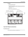
1
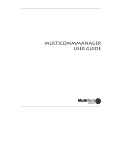
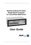
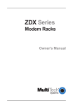
PS9648 Power Supply
User Guide
PS9648 Power Supply User Guide
P/N 82074300, Revision A
Copyright © 1998 by Multi-Tech Systems, Inc.
All rights reserved. This publication may not be reproduced, in whole or in part, without prior expressed
written permission from Multi-Tech Systems, Inc.
Multi-Tech Systems, Inc. makes no representation or warranties with respect to the contents hereof and
specifically disclaims any implied warranties of merchantability or fitness for any particular purpose.
Furthermore, Multi-Tech Systems, Inc. reserves the right to revise this publication and to make changes
from time to time in the content hereof without obligation of Multi-Tech Systems, Inc., to notify any
person or organization of such revisions or changes.
Revision
Date
A
3/25/98
Description
Manual Released
Multi-Tech, CommPlete, and the Multi-Tech logo are trademarks of Multi-Tech Systems, Inc. Other
trademarks and trade names mentioned in this publication belong to their respective owners.
Multi-Tech Systems, Inc.
2205 Woodale Drive
Mounds View, Minnesota 55112
(612) 785-3500 or (800) 328-9717
U.S. Fax (612) 785-9874
Technical Support (800) 972-2439
BBS (612) 785-3702 or (800) 392-2432
Fax Back (612) 717-5888
Internet Address: http://www.multitech.com
Federal Communications Commission Statement
This equipment has been tested and found to comply with the limits for a Class A digital device, pursuant
to Part 15 of the FCC Rules. These limits are designed to provide reasonable protection against harmful
interference when the equipment is operated in a commercial environment. This equipment generates,
uses, and can radiate radio frequency energy, and if not installed and used in accordance with the instruction manual, may cause harmful interference to radio communications. Operation of this equipment
in a residential area is likely to cause harmful interference, in which case the user will be required to
correct the interference at his own expense.
Warning: Changes or modifications to this unit not expressly approved by the party responsible for
compliance could void the user’s authority to operate the equipment.
CommPlete Communications Server
iii
iv
CommPlete Communications Server
Table of Contents
1 Introduction
Introduction ...................................................................................................................................................... 2
Description ........................................................................................................................................................ 2
Features......................................................................................................................................................... 2
Technical Specifications.................................................................................................................................... 3
Manual Organization......................................................................................................................................... 3
2 Installation
Introduction ...................................................................................................................................................... 6
Pre-Installation Notes ....................................................................................................................................... 6
Installation Procedure....................................................................................................................................... 6
3 Operation
Introduction ...................................................................................................................................................... 8
Power Switch ..................................................................................................................................................... 8
Power Indicator ................................................................................................................................................. 8
4 Solving Problems
Introduction .....................................................................................................................................................10
LED Indicators..................................................................................................................................................10
Power Supply LED............................................................................................................................................10
Adjustment of the PS9648 Power Supply.........................................................................................................10
Important Safety Considerations.....................................................................................................................11
Fuse Replacement........................................................................................................................................11
Insertion and Removal of a Power Supply ..................................................................................................12
Safety Disconnect Device.............................................................................................................................12
5 Warranty, Service, and Technical Support
Limited Warranty.............................................................................................................................................14
Service...............................................................................................................................................................14
Technical Support ............................................................................................................................................15
Recording Product Information..................................................................................................................15
The Multi-Tech BBS .........................................................................................................................................16
Logging onto the Multi-Tech BBS ...............................................................................................................16
Downloading a File ......................................................................................................................................16
Reading a Message.......................................................................................................................................17
Leaving a Message........................................................................................................................................17
Bulletins .......................................................................................................................................................17
About CompuServe...........................................................................................................................................17
About the Internet ............................................................................................................................................18
About the Multi-Tech Fax-Back Service ..........................................................................................................18
Index
CommPlete Communications Server
v
vi
CommPlete Communications Server
1
CommPlete Communications Server
Introduction
1
PS9648 Power Supply User Guide
Introduction
This manual describes the field installation of a Multi-Tech PS9648 power supply into a CommPlete
Communications Server CC9648 chassis. Installation and troubleshooting of the PS9648 should be
performed only by qualified service personnel.
Description
The PS9648 is a universal input switching power supply for the CommPlete Communications Server. Two
PS9648 power supplies are installed as standard equipment in each CommPlete CC9648 chassis. The
outputs of the two power supplies are connected in parallel to the CC9648 chassis power bus. If any of the
outputs on either power supply fails or is too low, the other power supply takes over with no switchover
time, and supplies all the power required to run the system. (This assumes that both power supplies are
turned on.)
Features
• Dual redundant, universal input switching supply.
• Front panel on/off switch and power LED indicator.
• Power LED lights only if all outputs are good.
• Outputs paralleled for redundancy.
• No switchover time for redundant supply takeover.
• Short circuit protection on all outputs.
• Over-voltage protection on 5 VDC output
• Logic level output signal for “All voltages OK.”
2
CommPlete Communications Server
1 Introduction
Technical Specifications
Input voltage
40 to 72 VDC
Input current
10 A @ 48 V at full load
Output voltage at
maximum current
5 VDC @ 65 A
21 VDC @ 0.5 A
5 V regulation
± 1% at full load
Indicator
LED for power good indication
Environmental
Temperature range: 0°–40° C (32°–104° F)
Humidity range: 0–95% (noncondensing)
Dimensions
7.3 cm × 17.1 cm × 29.8 cm (H × W × D)
2.88 in.× 6.75 in.× 11.75 in. (H × W × D)
Weight
2.27 kg (4 lb 9 oz.)
Limited Warranty
Two years
Fuses
12 A 250 V fast blow (non-user replaceable)
Manual Organization
Chapter 1
Introduction
This chapter describes the PS9648, gives its technical specifications, and provides a guide to the
organization of the manual.
Chapter 2
Installation
This chapter describes how to install the PS9648 into the CommPlete chassis
Chapter 3 Operation
This chapter describes briefly how to operate the PS9648 power supply.
Chapter 4 Solving Problems
This chapter describes how to troubleshoot the PS9648 and adjust the output.
Chapter 5 Warranty, Service, and Technical Support
This chapter describes the warranty, and how to obtain technical support.
CommPlete Communications Server
3
2
CommPlete Communications Server
Installation
5
PS9648 Power Supply User Guide
Introduction
This chapter describes how to install the PS9648 power supply into a CommPlete Communication Server
CC9648 chassis. This equipment should be installed only by a qualified service person.
Pre-Installation Notes
• All installation must be done by a qualified service person.
• Warning: Interconnection directly, or by way of other apparatus, of ports marked “SAFETY
WARNING see instructions for use” with ports marked or not so marked may produce hazardous
conditions on the network. Advice should be obtained from a competent engineer before such a
connection is made.
• Warning: Ports that are connected to other apparatus are defined as SELV. To ensure conformity to
EN 41003, ensure that these ports are only connected to the same type on the other apparatus.
• To reduce emissions, be sure to use blanking plates to cover empty slots in the CC9648 chassis.
Installation Procedure
1. Unpack the PS9648 assembly from its packaging and save the packaging for possible future use. Perform a visual inspection of
the PS9648. If you are concerned about its condition, call Technical Support for instructions.
2. Make sure the PS9648 power switch is in the off (O) position.
3. Remove the cover plate on the CC9648 if necessary. The PS9648 is hot-swappable.
4. Holding the PS9648 by the front panel and bottom corners, place the PS9648 into the open power supply slot. Make sure that
the top rails on the PS9648 mate properly with the plastic guides in the CC9648.
5. Slowly slide the PS9648 into the CC9648 chassis until you feel the PS9648’s connectors mate with the CC9648’s connectors.
6. Tighten the PS9648’s retaining screws.
7. Turn the PS9648 power switch on to the on (I) position.
8. Observe the PS9648 “outputs good”LED. If it is not lit, see Chapter 4. If it is lit, proceed with normal CommPlete
Communications Server operation.
9. After you turn on the power supplies, you should check the 5V output. See page 10 for details. The supplies can be re-checked
as part of your regular system maintenance.
6
CommPlete Communications Server
3
CommPlete Communications Server
Operation
7
PS9648 Power Supply User Guide
Introduction
This chapter provides information about operating your PS9648 Power Supply after it is installed.
Power Switch
The PS9648 has a power switch on the front panel that is labeled with the international I (on) and O (off)
symbols. For the most reliable operation, both power supplies should be turned on whenever the
CommPlete Communications Server is operating.
Power Indicator
The power indicator lights if all outputs are good. If any one of the outputs on the power supply goes bad,
this indicator goes out. If a power supply fails and the redundant power supply is installed and turned on,
the good power supply takes over with no switchover time.
8
CommPlete Communications Server
4
CommPlete Communications Server
Solving Problems
9
PS9648 Power Supply User Guide
Introduction
This chapter provides information needed to identify and fix problems with the PS9648 power supply
module. Problems can be observed on the CommPlete system’s front panel LEDs, the control PC’s screen,
or via audio alarm or alarm report. In addition, problems can be found when performing the Diagnostic
Tests documented elsewhere in the CommPlete Communications Server User Guide.
LED Indicators
The CommPlete Communication Server’s front panels contains the following indicators.
• MR9600 controller LEDs.
• Modem card LEDs. The number of LEDs on your modem card may vary, depending on the type of
modem card in your chassis. Please refer to your modem’s user guide for LED descriptions.
• PS9648 power supply LED.
The PS9648 power supply LED is described below. Each of the other LED indicators is described in the
applicable manual.
Power Supply LED
This LED goes out if one of the PS9648 power supply outputs goes low or fails altogether. In normal
operation it is lit. The recovery procedure to be used depends on whether the CommPlete chassis has one
or two PS9648 power supplies installed.
Indication:
LED is on (either one or two PS9648s installed).
Meaning:
The power supply (or supplies) are operating properly.
Recovery:
No action required.
Indication:
LED is off (one PS9648 installed).
Meaning:
At least one of the outputs is low or out.
Recovery:
Turn off the power supply, remove it, and check the fuse. Replace the fuse if it is blown;
call Technical Support if the fuse is good (Chapter 5).
Indication:
LED is off (two PS9648s are installed).
Meaning:
At least one of the outputs is low or out. Power is being supplied by the second PS9648.
Recovery:
Turn off the PS9648 that has the LED off, and remove the PS9648. If fuse is blown, it must
be replaced by a qualified service technician (Chapter 5); call Technical Support if the fuse
is good (Chapter 5).
Adjustment of the PS9648 Power Supply
For optimal operation of the CommPlete Communications Server, the 5 V output of the PS9648 power
supply should be adjusted to 5.1 VDC. The 5-volt test points are located on the back of the chassis between
the power supply fans.
10
CommPlete Communications Server
4 Solving Problems
Procedure
1. Turn off the power supply that is not being adjusted.
2. Place your voltmeter’s probes on the test points.
3. Two trimpots, one for each power supply, are located on the back of the chassis between the power supply fans. Adjust the 5
volt trimpot that is closest to the power supply that you are testing to 5.1 VDC by turning it clockwise to increase the voltage, or
counterclockwise to decrease the voltage.
4. Check the measurement.
5. Repeat the above steps, as necessary, until the voltage is correct.
6. Repeat for the second PS9648 supply with the first PS9648 power supply turned off.
0 V test point (SELV)
5 V test point (SELV)
5 V adjust (right power supply)
5 V adjust (left power supply)
DC power (right power supply)
DC power (left power supply)
ALARM
CONFIG PORT
VIDEO
KEYBOARD
IN OUT
MONITOR
T1
ALARM
CONFIG PORT
VIDEO
KEYBOARD
IN OUT
MONITOR
T1
ALARM
VIDEO
KEYBOARD
CONFIG PORT
T1
IN OUT
MONITOR
CONFIG PORT
VIDEO
KEYBOARD
IN OUT
MONITOR
ALARM
-48V 0V
T1
-48V 0V
Figure 1. Power supply connectors and test points
Important Safety Considerations
Fuse Replacement
There is one replaceable fuse in the PS9648 power supply. Qualified service personnel may replace the fuse
with one of the same type and rating as indicated on the PS9648 Fuse Label.
CommPlete Communications Server
11
PS9648 Power Supply User Guide
Insertion and Removal of a Power Supply
Qualified service personnel may insert or remove a power supply without turning off the system. We
recommend that you insert the power supply slowly. If the power supply is not replaced, a cover plate
must be installed.
Safety Disconnect Device
The switches on the power supplies are not safety disconnect devices. To reduce the risk of electric shock,
unplug the two input power cords from the back of the CC9648.
Install the power outlet near the CC9648, and place the equipment so that the outlet is easily accessible.
12
CommPlete Communications Server
5
CommPlete Communications Server
Warranty, Service, and
Technical Support
13
PS9648 Power Supply User Guide
Limited Warranty
Multi-Tech Systems, Inc. (“MTS”) warrants that this product will be free from defects in material or
workmanship for a period of two years from the date of purchase, or, if proof of purchase is not provided,
two years from date of shipment.
MTS MAKES NO OTHER WARRANTY, EXPRESSED OR IMPLIED, AND ALL IMPLIED WARRANTIES OF
MERCHANTABILITY AND FITNESS FOR A PARTICULAR PURPOSE ARE HEREBY DISCLAIMED.
This warranty does not apply to any products which have been damaged by lightning storms, water, or
power surges or which have been neglected, altered, abused, used for a purpose other than the one for
which they were manufactured, repaired by the customer or any party without MTS’s written
authorization, or used in any manner inconsistent with MTS’s instructions.
MTS’s entire obligation under this warranty shall be limited (at MTS’s option) to repair or replacement of
any products which prove to be defective within the warranty period, or, at MTS’s option, issuance of a
refund of the purchase price. Defective products must be returned by Customer to MTS’s factory,
transportation prepaid.
MTS WILL NOT BE LIABLE FOR CONSEQUENTIAL DAMAGES AND UNDER NO CIRCUMSTANCES
WILL ITS LIABILITY EXCEED THE PURCHASE PRICE FOR DEFECTIVE PRODUCTS.
Service
If your technical support specialist decides that service is required and you are outside the USA, your local
distributor of Multi-Tech products usually offers the quickest and most economical repair option. If
necessary, you may send your Multi-Tech product to our Mounds View factory in the USA. A modem that
is shipped to us from outside the USA must have a Returned Materials Authorization (RMA) and shipping
instructions. To return a modem for repair from inside the USA, no RMA is required; simply send it to us
freight prepaid. Include a description of the problem, return billing and shipping addresses, a check or
purchase order for out-of-warranty repairs, and, if possible the name of the technical support specialist
you spoke to.
If you need to inquire about the status of the returned product, be prepared to provide its serial number.
Please send modems that require repairs to the following address:
Multi-Tech Systems, Inc.
2205 Woodale Drive
Mounds View, MN 55112
Attn: Repair
If you are shipping from outside the USA, please contact our Repair Department for an RMA prior to your
shipment. You can contact us by telephone at +(612) 785-3500 or by fax at +(612) 785-9874.
14
CommPlete Communications Server
5 Warranty, Service, and Technical Support
Technical Support
Multi-Tech has an excellent staff of technical support personnel available to help you get the most out of
your Multi-Tech product. If you have any questions about the operation of this unit, please call (800) 9722439 (USA and Canada) or (612) 785-3500 (local and international). Please record PS9648 information in
the spaces provided below, and have it available when you call. If your PS9648 requires service, the technical support specialist will guide you on how to send it in.
Recording Product Information
Please record the following information about your PS9648 to help Technical Support answer your questions. (The
same information is requested on the Warranty Registration Card.)
Model no.:_____________________________________________________________________
Serial no.: _____________________________________________________________________
Please note the status of your power supply in the space below before calling Technical Support. This
includes the LED indicator, screen messages, diagnostic test results, problems with a specific application,
etc.
____________________________________________________________________________
____________________________________________________________________________
____________________________________________________________________________
____________________________________________________________________________
____________________________________________________________________________
____________________________________________________________________________
____________________________________________________________________________
____________________________________________________________________________
____________________________________________________________________________
____________________________________________________________________________
____________________________________________________________________________
____________________________________________________________________________
____________________________________________________________________________
____________________________________________________________________________
____________________________________________________________________________
____________________________________________________________________________
____________________________________________________________________________
____________________________________________________________________________
____________________________________________________________________________
____________________________________________________________________________
CommPlete Communications Server
15
PS9648 Power Supply User Guide
The Multi-Tech BBS
Multi-Tech maintains a bulletin board system (BBS) for its customers. Information available from the BBS
includes new product information, product upgrade data, and problem-solving tips. There is also a message service that lets you request additional information. The phone number for the Multi-Tech BBS is
(800) 392-2432 (USA and Canada) or (612) 785-3702 (local and international).
The BBS can be accessed by any asynchronous modem operating at 1200 bps to 33,600 bps at a setting of 8
bits, no parity, and 1 stop bit (8-N-1).
Logging onto the Multi-Tech BBS
To log on to the Multi-Tech BBS, perform the following steps:
1. Set your communications program to 8-N-1.
2. Dial our BBS at (800) 392-2432 (USA and Canada) or (612) 785-3702 (international and local).
3. At the prompts, type your first name, last name, and password; then press ENTER. If you are a first time caller, the BBS will ask
if your name is spelled correctly. If you answer yes, a questionnaire will appear. You must complete the
questionnaire to use the BBS on your first call.
4. Press ENTER until the Main Menu appears. From the Main Menu you have access to three main areas: the Files Menu, the
Message Menu, and Bulletins. For help on menu commands, type ?.
Downloading a File
If you know the file name
1. From the Main Menu, type F to access the Files Menu, then type D.
2. Enter the name of the file you wish to download from the BBS.
3. If a password is required, enter the password.
4. Answer Y or N to the automatic logoff question.
5. Select a file transfer protocol by typing the indicated letter, such as Z for Zmodem (the recommended protocol).
6. If you select Zmodem, the transfer will begin automatically. If you select another protocol, you may have to initiate the transfer
yourself. (In most datacomm programs, the PAGEDOWN key initiates the download.)
If you don’t know the file name
1. From the Main Menu, type F to access the Files Menu. For a list of file areas, type L twice. (If you do not type the secondL, you
will list all of the files on the BBS.)
2. Mark the file areas you would like to examine by typing each file area’s list number and pressing ENTER.
3. Enter L to list all the files in the selected file areas. Enter C to go forward in the file list and P to go back.
4. Mark one or more files for download by entering M, the list numbers of the files, and pressing ENTER.
5. Enter D. You will see a list of the files you have marked. Enter E if you would like to edit the list; otherwise enter D again to start
the download process.
6. Select a file transfer protocol by typing the indicated letter, such as Z for Zmodem (the recommended protocol).
7. If you select Zmodem, the file will transfer automatically. If you select another protocol, you may have to initiate the transfer
yourself. (In most communications programs, the PAGEDOWN key initiates the download.)
8. When the download is complete, enter S to return to the File Menu.
16
CommPlete Communications Server
5 Warranty, Service, and Technical Support
Reading a Message
When you log on, the BBS will tell you if you have a personal message (mail). At the prompt Would
you like to read it now?, type R to read the message. This is the only point at which you
can read your mail, since you cannot read any messages from the Message Menu.
Leaving a Message
The Multi-Tech BBS has no public discussion area. To leave a personal message, select the Message Menu
by typing M at the Main Menu. Type E, then press ENTER to select the Sysop conference. Enter the name of
the recipient (or “Sysop”), the subject, and the message text. Press ESC to finish, then type S to save the
message and exit. To abort the message at any point, leave any of the fields blank and press ENTER.
Bulletins
When you log on, the BBS will ask if you would like to view the bulletin menu. The bulletins are menudriven; to read a bulletin, enter its number. You can also access the bulletins by typing B at the Main
Menu.
About CompuServe
In addition to the BBS, Multi-Tech provides support through CompuServe’s Modem Vendor Forum (GO
MODEMVEN) under GO MULTITECH. You can also download manuals, Help files, drivers, Microsoft Mail
scripts, and product tips and descriptions from the forum’s Multi-Tech library. Refer to your CompuServe
documentation for special operating procedures.
CommPlete Communications Server
17
PS9648 Power Supply User Guide
About the Internet
Multi-Tech is a commercial provider on the Internet, and we retrieve e-mail messages from the following
mailboxes on a periodic basis:
[email protected] Technical Support
[email protected]
Marketing Dept.
[email protected] Sales Dept.
[email protected] International Marketing & Sales
[email protected] Publications Dept.
Multi-Tech's presence includes a Web site at:
http://www.multitech.com
and an ftp site at:
ftp://ftp.multitech.com
The ftp server mirrors the Multi-Tech BBS.
About the Multi-Tech Fax-Back Service
Multi-Tech's fax-back service provides 24-hour access to sales, marketing, and technical literature for
customers in the USA. Dial (612) 717-5888, follow the voice prompts, and enter the document number for
either the Sales and Marketing catalog or the Technical Support catalog of documents. For convenience,
write your fax number in the following space: ___________________________________________.
From the Sales and Marketing catalog, you can request to have newsletters, white papers, press releases,
brochures, and other marketing literature faxed to you. From the Technical Support catalog, you can
request basic modem operation information and troubleshooting guides. With either catalog, simply enter
the FB Doc. number of the literature you wish to receive.
18
CommPlete Communications Server
Index
—A—
adjusting the output, 11
—M—
manual organization, 3
Multi-Tech BBS, 16
—B—
—O—
BBS, Multi-Tech, 16
operating the PS9648, 8
—C—
CC9648 chassis, 6
CompuServe, 17
—D—
—P—
power bus, 2
power cords, 12
power indicator, 6, 8, 10
power switch, 8
description, 2
dimensions of PS9648, 3
—S—
—F—
fax-back service, 18
features, 2
fuse, 3, 10
safety, 6, 12
service, 14
solving problems, 10
specifications, 3
switchover time, 2, 8
—T—
—I—
installation, 6
Internet, 2, 18
—L—
technical specifications, 3
technical support, 15, 17
test points, 11
troubleshooting, 10
—W—
LED, 10
warranty, 14
World Wide Web, 18
CommPlete Communications Server
19
PS9648 Power Supply User Guide
20
CommPlete Communications Server