1
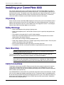
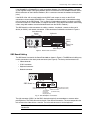
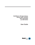
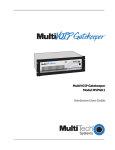
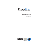
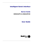
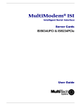
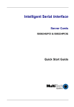
CommPlete 4000 Communications
Server
Quick Start Guide
CommPlete 4000 Communications Server
Quick Start Guide
S000347A, Revision A
This publication may not be reproduced, in whole or in part, without prior expressed written
permission from Multi-Tech Systems, Inc. All rights reserved.
Copyright © 2004, by Multi-Tech Systems, Inc.
Multi-Tech Systems, Inc. makes no representations or warranties with respect to the contents hereof
and specifically disclaims any implied warranties of merchantability or fitness for any particular
purpose. Furthermore, Multi-Tech Systems, Inc. reserves the right to revise this publication and to
make changes from time to time in the content hereof without obligation of Multi-Tech Systems, Inc.
to notify any person or organization of such revisions or changes.
Record of Revisions
Revision
A
Date
Description
05/21/04 Replacing printed Quick Start and including new SBC (IAC-F969 Series).
Patents
This product is covered by one or more of the following U.S. Patent Numbers: 5.301.274; 5.309.562;
5.355.365; 5.355.653; 5.452.289; 5.453.986. Other Patents Pending.
TrademarksTrademarks of Multi-Tech Systems, Inc. are as follows: CommPlete, RASExpress,
MultiExpressFax, and the Multi-Tech logo.
CompuServe is a trademark of CompuServe, Inc.
Multi-Tech Systems, Inc.
2205 Woodale Drive
Mounds View, Minnesota 55112
(763) 785-3500 or (800) 328-9717
Fax (763) 785-9874
Tech Support (800) 972-2439
Internet Address: http://www.multitech.com
2
CommPlete 4000 Communications Server Quick Start Guide
Contents
System Overview .........................................................................................4
Product Overview .................................................................................................................................... 4
RASExpress and Auxiliary Software .................................................................................................. 4
Installing your CommPlete 4000 .................................................................6
Unpacking ............................................................................................................................................... 6
Safety Warnings ...................................................................................................................................... 6
Rack Mounting ........................................................................................................................................ 6
Cable Connections .................................................................................................................................. 6
SBC Board Cabling ............................................................................................................................ 7
ISI Board Cabling ............................................................................................................................... 8
Serial Card Upgrades ........................................................................................................................ 9
Powering Up .......................................................................................................................................... 10
Quick Start with RASExpress ................................................................................................................ 11
What you need to start ..................................................................................................................... 11
Accessing RASExpress ................................................................................................................... 11
Method A. Do All Configuration using Terminal or Auxiliary PC ........................................................ 12
Method B. Start Configuration with Terminal, Finish Configuration on Client PC ............................. 14
WINMCSI Workstation Redirector ......................................................................................................... 16
Installing and Configuring the WINMCSI Redirector .............................................................................. 16
WINMCSI Installation ....................................................................................................................... 16
Running the WINMCSI Workstation Software ........................................................................................ 18
RADIUS Authentication & User Profile Software ................................................................................... 19
Requirements .................................................................................................................................. 19
Installing Radius Login Authentication Software ............................................................................... 19
Radius Server Properties ................................................................................................................ 20
Authentication .............................................................................................................................. 20
Accounting ................................................................................................................................... 20
Account Directory ........................................................................................................................ 20
Dictionary .................................................................................................................................... 20
Clients ......................................................................................................................................... 21
Users ........................................................................................................................................... 21
Realms ........................................................................................................................................ 21
Max Authentication Threads ........................................................................................................ 21
Max Accounting Threads ............................................................................................................. 21
Max Outstanding Requests ......................................................................................................... 21
Polling Interval for File Changes .................................................................................................. 21
Radius Software: “Clients” and “Users” Files .................................................................................... 22
CommPlete 4000 Communications Server Quick Start Guide
3
System Overview
System Overview
The CommPlete™ 4000 Communications Server is a single-segment, rack mountable
communications server. It is customized for dedicated turnkey operation of LAN-based
communications and remote access server functions. The CommPlete 4000 is a general purpose
server that easily interfaces to any existing Novell, Windows NT, or IP network.
Figure 1. CommPlete™ 4000 Communications Server
Product Overview
The CommPlete 4000 is a ruggedized, highly expandable 19" rack mount device that includes a builtin hard drive, 3.5" floppy drive, and a slot for a CD-ROM drive. It has five circuit-board slots: four are
PCI compatible, and one accommodates either a PCI or ISA card. Each CommPlete 4000 model is
shipped with a MultiModem ISI card an expansion slot leaving three slots for expansion cards. A
separate slot supports the single board computer (SBC) that is the heart of the system. A user
configurable card cage allows for up to 32 V.90 (56kbps, KFlex) internal modems or up to 32 high
speed serial ports. The CommPlete 4000 is shipped with factory-installed RASExpress server
software for remote-access functionality. Each CommPlete 4000 has a default configuration that
allows it to boot as a RAS unit. Additional software for authentication service and network modem
port allocation are also included.
The four CommPlete 4000 models differ according to the serial interface card used. The different
serial interface cards offer, variously, serial ports for external modems, built-in modems, or built-in
modems and terminal adapters:
Model CC4S-8 with the ISI4608PCI or ISI4608UPCI serial card -- has serial port connections for
eight external modems.
Model CC4M-8 with the ISI5634PCI/8 or ISI5634UPCI serial card -- has eight built-in modems
Model CC4H-4S with the ISIHIP-4S serial card -- provides four ISDN terminal adapters using the
S interface as well as eight analog modems (allowing eight concurrent sessions)
Model CC4H-4U with the ISIHP-4U serial card -- provides four ISDN terminal adapters using the
U interface as well as eight analog modems (allowing eight concurrent sessions)
The CommPlete 4000 has expansion capability for up to three additional MultiModem ISI circuit cards
(for additional modems/TAs). When multiple serial-interface cards are used, the CommPlete
accommodates or includes as many as 32 communications devices. While it is most common to use
multiple ISI cards all of the same type, you can equip a single CommPlete 4000 unit with more than
one type of ISI card.
RASExpress and Auxiliary Software
The CommPlete 4000 is equipped with factory installed RASExpress, an advanced remote access
software that enables network managers to configure and manage remote servers via web browsers,
through Telnet over an IP network, and via a GUI manager over both IP and IPX networks. Through a
4
CommPlete 4000 Communications Server Quick Start Guide
System Overview
special software package bundled with the CommPlete 4000, RASExpress can also be interfaced to
standard Radius authentication functionality (which resides on a separate PC).
RADIUS authentication software (Remote Authentication Dial-In User Service) handles authentication
and profile information about network users and secures against unauthorized server access. Built-in
R log protocol support permits remote log-in to all hosts on the network. RASExpress can facilitate
remote software upgrades via standard TFTP protocol.
The CommPlete 4000’s workstation re-director programs (WINMCSI and MCSIWSN) control modem
port assignments on the network.
CommPlete 4000
Single Processor
Data Communications Server
Terminals
EtherNet
LAN
RASExpress
Software
Ethernet Concentrator
SBC
Intelligent Serial
Interface Cards
ISI5634PCI/8
ISI5634PCI/8
ISI5634PCI/8
Ethernet 10BASET Concentrator
Model EN516TP/CA Active Hub for UTP Networks
1
2
3
4
5
6
7
8
9 10 11 12 13 14 15 16
Dial-Up
Lines
ISI5634PCI/8
Printer
Print
Server
File
Server
Figure 2. Typical RASExpress Application - Dial-In Remote Access
Figure 2b. Typical RASExpress Application - Dial-Out Services
CommPlete 4000 Communications Server Quick Start Guide
5
Installing Your CommPlete 4000
Installing your CommPlete 4000
This chapter explains how to set up and connect cables for the CommPlete 4000. This product is
ready to be connected to the end-user's Ethernet concentrator. It is preconfigured to operate as a
communications server. The operator must make modem/terminal-adapter connections, link up the
VGA monitor and keyboard, boot the system, and enter some basic information. To connect the
cables to the SBC or ISI board, see the Cable Connections section of this chapter.
Unpacking
Check the items on the CommPlete 4000 shipping list to ensure that you have received the correct
options and accessories. Unpack the unit and inspect it for visible shipping damage. If damage is
observed, do not power-on the unit; contact Multi-Tech's Tech Support for advice. If no damage is
observed, place the CommPlete 4000 in its final location.
Safety Warnings
• Never install telephone wiring during a lightning storm.
• Never install telephone jacks in wet locations unless the jack is specifically designed for wet
locations.
• This product is to be used with UL and cUL listed computers.
• Never touch uninsulated telephone wires or terminals unless the telephone line has been
disconnected at the network interface.
• Use caution when installing or modifying telephone lines.
• Avoid using a telephone (other than a cordless type) during an electrical storm. There may be a
remote risk of electrical shock from lightning.
• Do not use the telephone to report a gas leak in the vicinity of the leak.
• To reduce the risk of fire, use only No. 26 AWG or larger telecommunications line cord.
Rack Mounting
Caution: To prevent personal injury or damage to the unit, two people should mount the
CommPlete 4000 into the rack enclosure.
The CommPlete 4000 fits in a standard 19-inch rack enclosure. Attach it securely to the rack
enclosure with the four mounting screws included in your CommPlete 4000 kit.
Note: To keep the server cool enough, you need at least one inch of clearance behind the
unit to allow air flow. If mounted in a rack enclosure or as a desktop unit, there must be a
minimum of one inch between the back of the CommPlete 4000 and any wall or barrier.
Cable Connections
The operator must connect the SBC’s Ethernet connection to the network and the serial interface
card(s) to their related external devices or telephony connections. If the ISI5634PCI/8 is used, the
supplied special cables with two sizes of modular phone plugs must be used to connect that board’s
built-in modems to the phone lines.
If the ISI5634UPCI/8 is used, two RJ-45’s provide the connections to their external devices. The RJ45’s fan out to support four modem connections per jack. Two special cables are provided with the
RJ-45 connecting to the UPCI board and fanning out to four RJ11 jacks. The cables are labeled 1-4
which connect to the bottom (right) RJ-45 on the UPCI board and the second cable is labeled 5-8
which connect to the top (left) RJ-45.
6
CommPlete 4000 Communications Server Quick Start Guide
Installing Your CommPlete 4000
If the ISI4608PCI or ISI4608UPCI is used, connections between it and external modems are made
via the supplied octopus cable going between the DB-78 connector on the ISI4608PCI board and the
DB-25 connectors on the individual modems. (RJ-11 connectors connect the modems to the phone
jacks.)
If the ISIHP-4S or -4U are used, note that each ISIHP card accepts as many as four RJ-45
connectors to accommodate ISDN BRI lines. (The modem connections that accommodate analog
calls are internal to the ISIHP board. That is, when the V.90 modem module is installed, each ISDN
B-channel connects to a V.90 modem via a digital connection. These digital connections allow analog
callers using 56K modems to receive 56k downloads from the ISIHP’s modems.)
The SBC board has cable connectors for adding a monitor, a keyboard, a mouse or other serial
device (on COM1), and network connection. Cable connectors and boards are shown in Figure 3.
Cover Mounting
Screws
ISI Boards
MODEM
Line
5-8
MODEM
Line
1-4
MODEM
Line
5-8
MODEM
Line
1-4
Cover
COM 2
(DB15)
120
Printer Port
(DB25)
Power Supply
SBC Backplane
Figure 3. Back Panel Connectors
SBC Board Cabling
The SBC board is located in the CommPlete 4000 as shown in Figure 3. The SBC board cabling may
involve connection to four back panel connectors (see Figure 4). The back panel connectors are:
• Video connector
• COM 1 connector
• Keyboard connector
• Network connector
120
SBC Board
DB9 (male) Connector
6-Pin Circular Jack
(to COM 1 Serial Port)
(To External Keyboard)
15-Pin Video RJ45 Connector
(to Network Hub)
Connector
(to External
Display Monitor)
Fig. 4. SBC Backplane Connections
The right connector (COM 1) on the SBC’s backplane typically accommodates a mouse or other
pointing device. The RJ45 connector to the left is the network connection. The next receptacle to the
left connects the video cable to a monitor. The left round connector is for the keyboard.
Note: Any cables connected to the CommPlete 4000 should be shielded to reduce
interference.
CommPlete 4000 Communications Server Quick Start Guide
7
Installing Your CommPlete 4000
ISI Board Cabling
Each Intelligent Serial Interface card (ISI5634PCI/8, ISI5634UPCI/8, ISI4608PCI, ISI4608UPCI or
ISIHP-2S/2U) takes up one physical slot in the CommPlete 4000. Depending on your configuration,
you may have as many as four of these cards (see Figure 3). Attach the line cords (RJ-12 for analog
phone lines; RJ-45 for UPCI or ISDN phone lines) to the line connectors on the ISI card(s) at the
back of your CommPlete 4000 as shown in Figure 5.
ISI5634UPCI/8
RJ45 Line Jacks
Modem
Line
1-4
Modem
Line
5-8
MODEM
LINE
5-8
MODEM
LINE
1-4
120
RJ12 Line Jacks
ISI5634PCI/8 Board
Figure 5: ISI Board Connectors (ISI5634PCI/8 and ISI5634UPCI shown;
other MultiModem ISI cards differ)
Note: Any cables connected to the CommPlete 4000 should be shielded to reduce
interference.
Note that the two top expansion slots share a data interrupt signal on the PCI bus. Consequently, if
both slots are used, they must be occupied with identical devices (and the device drivers must be
identical). This is a constraint of PCI bus architecture. Also, the device drivers must support
“interrupt-sharing.” The drivers for the MultiTech ISI card do support interrupt-sharing.
Shared Interrupt
for Top Slots.
Identical Devices Required.
You can not mix PCI &UPCIcards
in these two slots, because they
use different drivers.
120
Figure 5b. Top Slots Require Identical Devices
8
CommPlete 4000 Communications Server Quick Start Guide
Installing Your CommPlete 4000
Serial Card Upgrades
As shown in Figure 5c, installation of expansion cards is simpler in the outer slots than in the inner
expansion slot.
Shipped Configuration
120
120
Preferred
expansion
slots
120
Installing expansion card here
requires removal of card cage.
}
Figure 5c. Convenience of using outer expansion slots before the inner slot
CommPlete 4000 Communications Server Quick Start Guide
9
Installing Your CommPlete 4000
Powering Up
Note: This is pluggable equipment; the socket outlet must be installed near the equipment and must
be easily accessible.
Make sure that the voltage selector on the power supply is set to the proper voltage prior to
connecting this equipment to the main power. If the voltage selector needs to be changed, an
ordinary pencil can be used to change the switch to the position which best correlates with the known
input voltage. If the voltage selector is in the "115" position, input voltages from 100-120VAC may be
applied to the equipment. If the voltage selector is in the "230" position, input voltages from 200-240
VAC may be applied to the equipment.
Connect the power cord supplied with the CommPlete 4000 to the power cord connector on the back
of the cabinet and to an AC outlet. Press the power switch on the front of the cabinet to the ON
position. The power switch contains an LED which should light when power is applied.
120
Power Supply
Monitor Power
Outlet
120
Power Cord
Input
Voltage Selector
Fig. 6. Power Supply Connectors
10
CommPlete 4000 Communications Server Quick Start Guide
Installing Your CommPlete 4000
Quick Start with RASExpress
MultiTech Systems has preinstalled RASExpress server software on your CommPlete 4000 to make
configuration as simple as possible. For your convenience, a copy of the RASExpress Installation
program is on the CD-ROM shipped with the CommPlete 4000. Complete the procedure below to put
your CommPlete 4000 into operation as a Remote Access Server.
What you need to start
•
The CommPlete 4000 Server
•
A dumb terminal or an auxiliary PC (other than the CommPlete 4000 itself) that can operate
in terminal mode
•
A shielded RS-232C serial cable with a female DB-9 connector on one end and a connector
to match the serial port of the terminal or auxiliary PC on the other end (supplied)
•
An IP Address assigned to the CommPlete 4000 server
•
An IP Subnet Mask assigned to the CommPlete 4000 server
•
Optional: a client PC connected to the CommPlete 4000’s network and equipped with Telnet,
a browser, or MultiManager
Accessing RASExpress
To configure the CommPlete 4000 as a RASExpress server, you must first connect a terminal or
auxiliary PC to the CommPlete 4000’s serial port. Then you must enable IP Remote Access and
program the IP Address and IP Subnet Mask into the CommPlete 4000. After the IP Address and
IP Subnet Mask have been entered into the CommPlete 4000, you can either:
(a)
(b)
continue using the terminal or auxiliary PC to program other network settings into the
CommPlete 4000, or
re-boot the CommPlete 4000 and then continue programming the CommPlete 4000’s
network settings from a client PC connected to the LAN in which the CommPlete 4000
is the RAS server. Do this using Telnet, or a browser, or MultiManager.
The steps for both methods are presented below.
CommPlete 4000 Communications Server Quick Start Guide
11
Getting Started with RASExpress
Method A. Do All Configuration using Terminal or Auxiliary PC
A1.
Be sure that the CommPlete 4000 is connected to the LAN. Turn off the power for the
CommPlete 4000.
A2.
Using the provided RS-232C serial cable, connect a terminal (or an auxiliary PC) to the
CommPlete 4000’s serial port.
120
Connect RS-232C
Serial Cable (female end)
here
SBC
Backplane
6-Pin Circular Jack
(To External Keyboard)
15-Pin Video
Connector
(to External
Display Monitor)
RJ45
Connector
(to Network
Hub)
COM 1
DB9 male
RS232C
Cable
Dumb Terminal
or
Auxiliary PC
A3.
Figure 7: Serial port on the CommPlete 4000
Power up the CommPlete 4000. The RASExpress Server Screen will appear.
Note: The server takes a few moments to load the RASExpress software and to initialize the
modems after it is turned on. Observe RAS software processing and displaying .
A4.
Turn on the terminal (or auxiliary PC) and press Enter.
A5.
Select Quick Configuration of Server.
A6.
Enable IP Remote Access.
Note: Error messages will appear and will indicate that the remote addresses of the WAN
ports are not on the same subnet. This is normal for the initial setup. Ignore these messages.
A7.
Type the IP Address for the CommPlete RASExpress server.
A8.
Type the IP Subnet Mask.
A9.
In the IP Default Route field, enter the router address for the LAN’s file server.
A10. If you want the RASExpress server to use IP Routing Information Protocol (RIP-2) for IP
routing, enable IP RIP.
A11. If you have enabled IP-RIP, you may enable IP Auto Learn Default Gateway. When
enabled, the RASExpress server will learn the correct default gateway if it was configured
incorrectly or if the configured gateway goes down and a different router starts acting as a
default router.
12
CommPlete 4000 Communications Server Quick Start Guide
Getting Started with RASExpress
A12. In the Primary Name Server field and the Secondary Name Server fields,
type
000.000.000.000
unless you have made other arrangements.
A13. In the IP Frame Type field, select TYPE_II (the default value).
A14. If you set the Remote Client IP Address field to the value Configure Per Port,
follow these steps when this present Quick Configuration procedure is done:
i.
From the terminal main menu, select Configuration of server
ii.
Select Communication Setup.
iii.
Select ISI Setup.
iv.
Delete all ISI cards before saving and rebooting the server.
These steps correct the initial subnet error the next time the server loads.
If you set the Remote Client IP Address to any of these values (Use DHCP, or Use
Address Pool, Use Radius), go to step A15. If you selected Use Address Pool,
you must configure the address pool. See the RASExpress User Guide.
A15. When the above steps are complete, press Esc and save the changes to disk. You will be
asked to re-boot the server.
A16. Type Y and press Enter. The connection closes while the RASExpress server re-boots. A
new menu appears after the CommPlete 4000 has re-booted.
A17. To complete the configuration of the RASExpress server, select Configuration of
server from the main menu. For detailed information about the menu options, see Chapter 3
of the RASExpress manual.
CommPlete 4000 Communications Server Quick Start Guide
13
Getting Started with RASExpress
Method B. Start Configuration with Terminal, Finish Configuration on Client PC
To enable remote configuration of the RASExpress server, you must first configure the server’s IP
settings, including the server’s IP address. To do this, you must connect a terminal (or auxiliary PC)
to the server’s serial port. After IP is configured and working, you can complete the server
configuration remotely through Telnet, through a browser, or through MultiManager on a client PC
connected to the LAN.
B1.
Be sure that the CommPlete 4000 is connected to the LAN. Turn off the power for the
CommPlete 4000.
B2.
Using the provided RS-232C serial cable, connect a terminal to the RASExpress server’s
configuration port.
120
Connect RS-232C
Serial Cable (female end)
here
SBC
Backplane
6-Pin Circular Jack
(To External Keyboard)
15-Pin Video
Connector
(to External
Display Monitor)
RJ45
Connector
(to Network
Hub)
COM 1
DB9 male
RS232C
Cable
Dumb Terminal
or
Auxiliary PC
B3.
Figure 8: Serial port on the CommPlete 4000
Power up the CommPlete 4000. The RASExpress Server Screen will appear.
Note: The server takes a few moments to load the RASExpress software and to initialize the
modems after it is turned on. Observe RAS software processing and displaying .
B4.
Turn on the terminal (or auxiliary PC) and press Enter.
B5.
Select Quick Configuration of Server.
B6.
Enable IP Remote Access.
Note: Error messages will appear and will indicate that the remote addresses of the WAN
ports are not on the same subnet. This is normal for the initial setup. Ignore these messages.
14
B7.
Type the IP Address for the CommPlete RASExpress server.
B8.
Type the IP Subnet Mask.
B9.
Re-boot the CommPlete 4000.
CommPlete 4000 Communications Server Quick Start Guide
Getting Started with RASExpress
B10. Using Telnet for access requires that a TCP/IP protocol stack be loaded on the client PC.
Telnet access is possible both by dialing in through the RASExpress server and, more
commonly , through the LAN or Internet.
Client PC
running Telnet session,
web, or Windows
MultiManager
CommPlete 4000
RASExpress Server
Figure 9. Setup for completing RASExpress configuration from client PC
At a client PC connected to the LAN in which the CommPlete 4000 is the RAS server, start a
Telnet session using either dial-in access or TCP/IP access.
CommPlete 4000 Communications Server Quick Start Guide
15
WINMCSI Workstation Redirector
WINMCSI Workstation Redirector
Note: This material is for IP or IPX network users only.
This section describes how a client PC can use the MCSI (pronounced miksee) software redirector to
access the RASExpress server’s modems when using standard communications software.
WINMCSI.EXE is a Windows application for use with either IPX or IP networks. COMMAP.EXE can
be used with either IPX or IP networks.
Installing and Configuring the WINMCSI Redirector
The WINMCSI modem-sharing program manages access to a modem for inbound and outbound
calls. It allows Windows communications software packages that do not support INT6B or INT14 to
connect to Multi-Tech gateways such as RASExpress. It also detects other compatible
communications servers on your network and displays the resources they provide to eligible LAN
users.
WINMCSI Installation
Windows NT4.0, Windows 2000/2003:
1.
Turn on your client PC and log in to your LAN.
2.
Start Windows.
3.
Insert the CommPlete 4000 CD-ROM into the CD-ROM drive.
4.
Go to Start | Settings | Control Panel.
5.
Double-click the Add/Remove Programs icon.
6.
The Install/Uninstall Program menu appears. Click Install.
7.
Click Next. If you want to install WINMCSI as a 32-bit program, let Windows locate the proper
Install.exe file on the CD-ROM. If you want to install WINMCSI as a 16-bit program, type
a:\winmcsi\install.exe d:\software\Wsredir and go to the next appropriate subdirectory (for
Windows NT, go to the “NTmcsi” subdirectory.” Then specify the install.exe file.
8.
Click Finish.
9.
The WINMCSI Installation Program window appears.
WinMCSI Installation Program
WinMCSI COM Port Redirector
Welcome to WinMCSI. This Program allows
Windows Communications applications that
talk only to the local COM ports to access the
ports of a MultiTech Asynchronous
Communications Server which may be running
anywhere on the LAN.
This install program will install WinMCSI
for Windows.
Continue
10.
Abort
To continue with the WINMCSI installation, click Continue and go to step 11.
If you do not want to install WINMCSI, click the Abort button .
11.
The WINMCSI Install Configuration window appears.
In the Destination Directory box, type the name of the directory where you want to install
WINMCSI, if you do not want to accept the default, C:\COMMCSI. Under Network Type, select
the appropriate network type (IPX, NetBIOS, or IP).
Note: If you choose IP inthe Network Type box, you must have a TCP/IP protocol active
16
CommPlete 4000 Communications Server Quick Start Guide
WINMCSI Workstation Redirector
with the default IP router matched with the local IP address of the RASExpress server.
12.
Click Continue.
13.
When the Installing Multi-Tech WINMCSI dialog box appears, click Install.
14.
When installation is complete, the WINMCSI Installation dialog box appears.
WinMCSI Installation
Your SYSTEM.INI and WIN.INI files need to be modified.
You can let Install make the changes now or save the
changes to a file.
The following changes are to be made to the
SYSTEM.INI [Boot]
Current: COMM= C:\COMMCSI\commsci.drv
New:
COMM= COMMSCI.DRV
The following change is to be made to the WIN.INI
[Windows]
Current: Load= nwpopup.exe netdex.exe
New:
Load= xe netddex.exe c:\commcsi\commap.exe
Save changes to file
15.
Modify INI files now
Abort
Click Modify INI Files Now to have WINMCSI make changes to your SYSTEM.INI and
WIN.INI files.
Click Save Changes to File to have WINMCSI make a copy of the changes to be made and
store them in a file. You must make the changes yourself before you can run WINMCSI.
A screen appears later that tells you your installation is complete, and where your WIN.INI and
SYSTEM.INI files are backed up. If IP was selected in the WINMCSI Install Configuration
dialog box, the screen also asks if you want to set up the IP server list. Answer appropriately.
16.
The following message appears:
Do you want to login to Multi-Tech Asynchronous Communication
server when WINDOWS comes up?
Answer appropriately.
17.
The following message appears:
Do you want to Map now?
Click Yes if you want to map your COM Ports now, and go to step 18.
Click No if you want to map your COM Ports when you start WINMCSI, then go to step 19.
18.
The COM Port to MCSI Mapping window appears.
• If you want the first available line, click Map, then click Close, and go to the next
section.
• If you want a specific line, select a COM port in the Local Port list, then select the line
to which you want to map the COM port. The status message Mapped to MCSI
should appear above the Local Port list.
Note: If a serial mouse is connected to COM1, you must select a different local port.
• Click Unmap if you want to unmap a line.
• Click Search to search for lines on a server.
• Click Close when finished.
19.
The following message appears:
WINMCSI Successfully installed. Click OK.
20.
A message appears that tells you where your old SYSTEM.INI and WIN.INI files have been
backed up. It also tells you to restart Windows. Click Restart Windows.
CommPlete 4000 Communications Server Quick Start Guide
17
RADIUS Authentication & User Profile Software
Running the WINMCSI Workstation Software
Before running data communications software, LAN users should use WINMCSI to log on to the
communications server.
To log on to the communications server from a workstation
21.
ComMap should start automatically if the WIN.INI file was modified during installation. To start
ComMap manually, double-click the ComMap icon in the Start menu.
22.
If you have not previously done so, select the Setup menu to configure ComMap.
Network Type. The Network Type dialog box shows your current network type (IP, IPX, or
NetBIOS). To change the network type, click the appropriate type for your network. Click OK
when finished. You must restart Windows if you change this setting.
Note: Do not change the network type unless the network has changed. Also, make sure that
your SYSTEM.INI file contains device drivers specific to the selected network type.
Connect Timer. The MCSI Connect Timer dialog box shows the default value of the connect
timer in the Enter Connect Timer Value box. This value sets the time in seconds, in the range
0 through 60, that the MCSI emulator waits for a MCSI device to become available. To change
the value of the connect timer, type a different value in the box. Click OK when finished.
Baud Change. A check mark appears next to the Baud Change command to indicate that an
application can change the baud rate or other port parameters. If Baud Change is unchecked,
then an application cannot change the baud rate or other port parameters. To change this
setting, click Baud Change.
Default Login. Use the Default Login Parameters dialog box to automatically log into a
specific server whenever Windows runs. Select a server from the Available Servers box, then
type a user name and optional password. Click OK when finished. ComMap saves these login
parameters in your COMMCSI.INI file.
Note: You can use a text editor to edit the COMMMCSI.INI file, however you cannot change
the password because the password field is encrypted. Editing the password will corrupt the
file.
If there are no servers listed in the Available Servers box, type a server name in the Server
Name box, then click the Search button to search for a match. You can use * and ? as wild
card characters.
Port Type. Use this command to designate your mapped ports as outbound (available only
for calling out) or inbound (available only for calling in). A port cannot be both outbound and
inbound. You can designate one port as outbound and another as inbound.
18
CommPlete 4000 Communications Server Quick Start Guide
RADIUS Authentication & User Profile Software
RADIUS Authentication & User Profile Software
Requirements
Radius Server requires a 486-66 MHz or faster computer, preferably running Microsoft Windows NT
Server. The computer should have a hard disk, a CD-ROM drive, and LAN or WAN access. Radius
Server requires approximately 420 kB on the hard disk and space for the user database.
Installing Radius Login Authentication Software
MultiTech’s Radius software allows the CommPlete 4000 RAS Server to operate in conjunction with a
general LAN server.
1.
On the Radius Server computer, exit all Windows programs except Windows Explorer.
2.
Insert the compact disc supplied with your Multi-Tech Systems communications server into the
computer's CD-ROM drive.
3.
If Autorun does not display the installation menu, find Autorun.exe in the root folder of the
compact disc, and double-click it. The installation menu appears.
4.
In the Select Software to Install dialog box, select Radius.
The Multi-Tech Radius Server Setup wizard will appear.
5.
Follow the instructions in the Setup wizard to install Radius Server.
6.
When the Settings dialog box appears, click OK. The default values are appropriate in most
cases. Descriptions of each field on the Settings dialog box can be viewed in the section
“Radius Server Properties” directly following this procedure. Also, you can change these
settings at any time when Radius Server is running.
7.
Click Finish.
8.
Re-boot the computer. By default, Multi-Tech Radius Service runs automatically on startup. If
for any reason the Radius program was shut down, you can launch the program manually from
the Windows “Start” menu.
9.
To shut down the Radius program, click on the Radius icon at the lower left of the PC screen.
CommPlete 4000 Communications Server Quick Start Guide
19
RADIUS Authentication & User Profile Software
Radius Server Properties
When Radius Server is running, the Radius Server icon appears in the Taskbar tray. To configure
Radius Server, right-click the icon and select Properties from the context menu. The following dialog
box appears:
Authentication
The RADIUS server port number. The default port number (1813) is required for Radius Server to
work with RASExpress.
Accounting
The RADIUS accounting port number. The default port number (1812) is required for Radius Server
to work with RASExpress.
Account Directory
The path where accounting logs are stored.
Dictionary
The name of the dictionary file. The dictionary file is an ASCII text file containing translations for
parsing requests and generating responses. This name cannot be changed.
Clients
The name of the clients file. The clients file is an ASCII text file containing the IP addresses and
shared secrets of the clients (RASExpress servers) served by Radius Server. This name cannot be
changed.
Users
The name of the users file. The users file is an ASCII text file that lists authentication and
configuration information for each user. This name cannot be changed.
20
CommPlete 4000 Communications Server Quick Start Guide
RADIUS Authentication & User Profile Software
Realms
The name of the realms file. The realms file is an ASCII text file that lists authentication servers to
which a specific authentication request can be forwarded. This name cannot be changed.
Max Authentication Threads
The maximum number of threads that can be run at one time to perform authentication operations.
Max Accounting Threads
The maximum number of threads that can be run at one time to perform accounting operations.
Max Outstanding Requests
The maximum number of requests that can be queued up for processing.
Polling Interval for File Changes
The period in minutes after which the configuration files (users, realms, clients) are polled to check
whether they have been modified recently. If they have been modified, the corresponding data
structures are then dynamically updated.
Radius Software: “Clients” and “Users” Files
After installing the Radius software, the administrator must customize the “Clients” file and the
“Users” file for use in their specific network system. These files can be found in C:\Program
Files\MultiTech Systems\Radius Server. The “Clients” file and the “Users” file can both be opened in
Notepad or Wordpad text-processor application programs.
In the “Clients” file, the administrator specifies the IP address of the RAS Server and the “shared
secret” known to both the CommPlete 4000 RAS server and to the password authentication server.
Entries in the “Clients” file must be in this form:
<IP address of client> <blank or tab(s)> <shared secret> <new line>
The IP addresses should be in dotted notation only. Names are not permitted.
For Windows NT only. In the “Users” file, the administrator lists network users by name and specifies
authentication/password parameters. The "users" file can include another file which contains a list of
users. The syntax is as follows:
$include <full path to the users file>.
When this command is employed under Windows NT, the authentication server can use the same
user database as the host server.
The first line in each user entry contains the following information:
<User name> <Tab> <Check List>
The <User name> field must start from the first column. The <Check List> field can have the
following info :
CommPlete 4000 Communications Server Quick Start Guide
21
RADIUS Authentication & User Profile Software
(i). Auth-Type. This field specifies whether the authentication is done locally or by the system (for
WindowsNT only). Values: Local or System.
(ii). Password = <The password of the particular user>
Indicates that PAP is the authentication protocol.
(iii). CHAP-Password = <The password of the particular user>
Indicates that CHAP protocol is the authentication protocol.
(iv). Prefix and Suffix.
The "users" file can also have DEFAULT entries which have the user name as DEFAULT. These
entries match on all users.
Concerning the notation, Fall-Through = 1 in the reply list,
=> the user entries which follow this user entry are also examined.
For NT Domain Authentication, the check list in the user entries can contain the attribute "Domainname," to indicate the domain in which the user is authenticated. For NT Domain Auth to work
properly, the person who has logged on should be given the rights "Act as part of the operating
System" and "Log On as Batch Job".
22
CommPlete 4000 Communications Server Quick Start Guide
RADIUS Authentication & User Profile Software
CommPlete 4000 Communications Server Quick Start Guide
23
S000347A