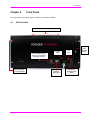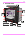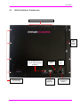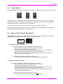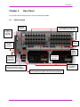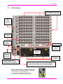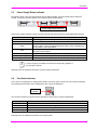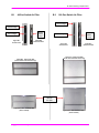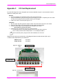
1
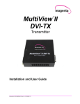
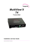
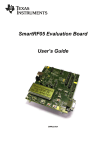
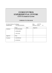
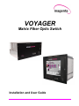
VOYAGER Matrix Fiber Optic Switch Installation and User Guide Document #5310251-01 © 1998-2011 by Magenta Research, LTD All rights reserved. Magenta Research, LTD 128 Litchfield Road New Milford, CT 06776 USA This document and the Magenta Research LTD products to which it relates, and the copyright in each, is the property of Magenta Research LTD. Neither the document nor the products may be reproduced by any means, in whole or in part, without the prior written permission of Magenta Research. Magenta Research makes no warranty or representation, either express or implied, with respect to this software or documentation, including their quality, performance, merchantability, or fitness for a particular purpose. As a result, this software or documentation is licensed "as is" and you, the licensee, are assuming the entire risk as to their quality and performance. In no event will Magenta Research be liable for direct, indirect, special, incidental, or consequential damages arising out of the use of or inability to use the hardware, software, or documentation. Magenta Research and the Magenta Research logo are trademarks of Magenta Research, LTD All other brands, product names, and trademarks are the property of their respective owners. Magenta Research reserves the right to change product functionality and/or specifications at any time without prior notification. Voyager Matrix Fiber Optic Switch Installation and User Guide ii Precautions Precautions This symbol calls attention to important information. This symbol is intended to alert the user of important maintenance (servicing) and operating information. This symbol is intended to alert the user to the presence of un-insulated dangerous voltages or other conditions in or around the product enclosure which may present a risk of electric shock, damage to equipment or facilities. This symbol is intended to alert the user of potentially dangerous invisible laser radiation. Caution: Read instructions: Read and understand all operating, installation and safety instructions before using this equipment. Avoid Attachments: Do not use accessories, attachments, tools, or materials that are not recommended by the equipment manufacturer. Doing so may compromise operating performance, create an unsafe condition, damage equipment, or violate the terms of usage or warranty. Follow Warnings: Always follow all instructions and warnings marked on the equipment or as detailed in the related user documentations. Voyager Matrix Fiber Optic Switch Installation and User Guide iii Safety Instructions Safety Instructions Read and understand all operating, installation, and safety instructions before using this equipment. Follow all instructions and warnings marked on the equipment or as detailed in this document. This equipment is to be installed in a restricted access location. There are NO user-serviceable parts inside; refer all servicing to qualified service personnel. This equipment should be operated only from the power source indicated on the product. This equipment is intended to be used with a main power system with a grounded (neutral) conductor. The third (grounding) pin is a safety feature, do not attempt to bypass or disable it. This equipment also has a separate protective earthing terminal located near the power supply modules. In order to avoid potentially hazardous shocks, this terminal must be permanently connected to the installation’s protective earth ground. This equipment has multiple AC inputs for redundant power supplies. DISCONNECT ALL POWER SOURCES BEFORE SERVICING. The AC inlet on the back of the power supply module is intended to be used as the main disconnect device. This equipment makes use of SFP Transceiver modules that are classified as Class 1 Laser Products. These products comply with US FDA regulations and are certified by TUV and CSA to meet the Class 1 safety requirements of EN (IEC) 60825 and the electrical safety requirements of EN (IEC) 60950. Do not use accessories, attachments, tools or materials that are not recommended by the equipment manufacturer. Doing so may compromise operating performance, create an unsafe condition, damage equipment, and/or violate the terms of usage or warranty. Openings in the enclosure are provided to prevent overheating of sensitive components inside. These openings must never be blocked by other objects. There is a danger of explosion if lithium battery is incorrectly replaced. Replace it only with the same or equivalent type recommended by the manufacturer. Dispose of used batteries according to local laws. Battery is not intended to be a user-serviceable part. Voyager Matrix Fiber Optic Switch Installation and User Guide iv Contact Information Contact Information For sales or technical support, contact your nearest Magenta Research sales office. REGION CONTACT DETAILS North, Central and South Americas: Magenta Research, LTD Corporate Headquarters 128 Litchfield Road New Milford, CT 06776 USA Main: 800-805-0944 (USA only) or +1 860-210-0546 Fax: 1-860-210-1758 Web: www.magenta-research.com Sales: [email protected] Support: [email protected] Sales/Support phone hours: 8:30-17:30 (EST: GMT-0500) Asia: Magenta Research Asia Limited Unit 1 21/F Cheung Tat Centre Chai Wan, Hong Kong Main: 852.3105.1493 Fax: 852.3105.1491 Contact: [email protected] Sales: [email protected] Pan European Office: Magenta Research, LTD Main: +44 7708-850582 Contact: [email protected] Sales: [email protected] For all RMA return shipments, use this address unless you are advised otherwise: Magenta Research, LTD RMA Department 128 Litchfield Road New Milford, CT 06776 USA Prior to returning any products, please contact Magenta’s support line to obtain an RMA number. This RMA number is essential for tracking your returns and for ensuring they are processed in a timely manner. Support Phone: 800-805-0944 (USA only) or +1 860-210-0546 Support e-mail: [email protected] Support phone hours: 8:30-17:30 (EST: GMT-0500) Voyager Matrix Fiber Optic Switch Installation and User Guide v Table of Contents Table of Contents Page Chapter 1 Introduction ................................................................................................................................ 1 Chapter 2 Specifications ............................................................................................................................. 2 Chapter 3 Installation .................................................................................................................................. 3 3.1 Prerequisites ................................................................................................................... 3 3.2 General Installation Information ...................................................................................... 3 3.3 Earth Grounding .............................................................................................................. 4 Chapter 4 Front Panel ................................................................................................................................ 5 4.1 48-Port Switch ................................................................................................................. 5 4.2 160-Port Switch (with Touchscreen) ............................................................................... 6 4.3 160-Port Switch (no Touchscreen) ................................................................................. 7 4.4 Keylock Switch ................................................................................................................ 8 4.5 Power / Control Switch (“Pushbutton”) ............................................................................ 8 4.6 Power Status Indicator (“Pilot Light”) .............................................................................. 9 4.7 Status Indicator Bar (“Dashboard”) ................................................................................. 9 Chapter 5 Rear Panel ............................................................................................................................... 11 5.1 48-Port Switch ............................................................................................................... 11 5.2 160-Port Switch ............................................................................................................. 12 5.3 Power Supply Status Indicator ...................................................................................... 13 5.4 Fan Status Indicator ...................................................................................................... 13 5.5 Rear Panel Status Indicator and Reset Button ............................................................. 14 5.6 I/O Card Status Indicators ............................................................................................. 15 Chapter 6 Powering Up / Powering Down ................................................................................................ 16 6.1 Power Up ...................................................................................................................... 16 6.2 Power Down .................................................................................................................. 17 Chapter 7 Control Overview ..................................................................................................................... 18 7.1 Switch Control ............................................................................................................... 18 7.2 Internal Block Diagram .................................................................................................. 19 7.3 Serial Interface Format ................................................................................................. 19 7.4 Physical Description ...................................................................................................... 20 7.5 Control Port Designation ............................................................................................... 21 Chapter 8 System Power & Thermal Management .................................................................................. 22 8.1 Response to Major System Faults ................................................................................ 22 8.2 Response to Critical System Faults .............................................................................. 22 Chapter 9 Switch “Input” and “Output” Ports ............................................................................................ 23 9.1 Simplex Switch Configuration ....................................................................................... 23 9.2 Duplex Switch Configuration ......................................................................................... 23 Chapter 10 Troubleshooting ....................................................................................................................... 24 Appendix A Fiber Optic Cabling .................................................................................................................. 25 A.1 Cable Recommendations .............................................................................................. 25 A.2 Fiber Optic Cable Terminology ..................................................................................... 26 Appendix B Air Filter Cleaning / Replacement ............................................................................................ 27 B.1 48-Port Switch Air Filter ................................................................................................ 28 B.2 160-Port Switch Air Filter .............................................................................................. 28 Appendix C I/O Card Replacement ............................................................................................................. 29 Appendix D Power Supply Replacement ..................................................................................................... 30 Appendix E Fan Tray Assembly Replacement ............................................................................................ 31 Voyager Matrix Fiber Optic Switch Installation and User Guide vi Table of Contents Appendix F Alarm Relay Output Behavior .................................................................................................. 32 F.1 Audible Alarm Behavior ................................................................................................ 32 Appendix G Regulatory Compliance Information ......................................................................................... 33 Index ................................................................................................................................................. 34 Voyager Matrix Fiber Optic Switch Installation and User Guide vii Introduction Chapter 1 Introduction The Voyager product line basically consists of two types of elements: Video extension links: Voyager VG-TX2 and VG-RX2. Hereafter referred to as “Voyager links”. Video matrix switch: VG-Matrix. Hereafter referred to as “Voyager switch” or “Voyager matrix”. This document details the installation, configuration, and technical specifications of the Voyager Matrix switch. The Voyager switch chassis contains a high-speed, video-switching backplane and additional support systems relating to power, cooling, and system management. There is also an optional built-in Touchscreen computer, which is used for local system control and diagnostics. Voyager Matrix Fiber Optic Switch Installation and User Guide 1 Specifications Chapter 2 Specifications ITEM Fiber Optic Cable Required DESCRIPTION LC-terminated, fiber-optic cables When using multi-mode SFP optic modules: Compatible with standard OM1 through OM4-grade (and better) cables. When using single-mode SFP optic modules: Compatible with standard OS1, OS2-grade (and better) cables. Please also refer to the Voyager link user guide for additional details regarding fiber-optic cables. (Voyager link user guide is available for download at www.magenta-research.com or scan the QR code shown here to access the guide directly: Compliance CE, FCC Part 15 Class A, C-Tick, cTUVus, RoHS Serial Characteristics Default Serial Format: 9600 baud rate, no parity, 8 data bits, 1 stop bit (9600,n,8,1) Available Baud Rates: 2400, 4800, 9600, 19200, 38400, 57600, 115200, 230400 Available Data Formats: 7- or 8-bit ASCII (high bit is forced to 0) Available Parity Bits: Odd, even, none, mark, space Available Stop Bits: 1, 1.5, 2, none Available Handshaking: None Connectors USB (Host): 3, Type “A” (if Touchscreen PC option is installed) USB (Device): 1 Type, “B” Serial: 3, DB-9F (plus 1, DB-9M if Touchscreen PC option is installed) LAN: 1, RJ-45 (plus 1, RJ-45 if Touchscreen PC option is installed) Alarm Relay: 3-pin Phoenix 160-Port I/O: Up to 160 SFP Transceiver Modules (Duplex LC Connector). 48-Port I/O: Up to 48 SFP Transceiver Modules (Duplex LC Connector). Temperature Tolerance Operating: 32 to 104°F (0 to 40°C); Storage: -4 to +140°F (-20 to +60°C) Humidity Tolerance Up to 80% noncondensing Air Filter Recommended service interval: 30 days Enclosure Type Front Panel: Powder coat over aluminum Enclosure: Aluminum Power 110 - 240VAC, 50/60Hz, 9A per Power Supply Module 2 independent fully-redundant AC Mains inputs Size 160-Port: 15.75" H x 19.0" W x 16.9" D (40 cm H x 48.3 cm W x 43 cm D) 48-Port: 8.75” H x 19.0” W x 16.9” D (22.23 cm H x 48.3 cm W x 43 cm D) Weight 160-Port: 50.0 lb. (22.7 kg) maximum (depends on configuration) 48-Port: 27.0 lb (12.2 kg) maximum (depends on configuration) MTBF 100,000 hours Rack Mount 160-Port: Standard, 9 RU x 19” EIA 48-Port: Standard, 5 RU x 19” EIA Voyager Matrix Fiber Optic Switch Installation and User Guide 2 Installation Chapter 3 Installation The Voyager Matrix Fiber Switch is designed to be installed in a standard 19” wide rack fixture. The Voyager switch should be installed in a restricted access location, such as a secure equipment room. Ensure there is adequate ventilation space on the sides and rear of unit. It is not necessary to allow ventilation space above or below each Voyager switch frame. There are NO user-serviceable parts inside; refer all servicing to qualified service personnel. 3.1 Prerequisites The minimal set of installation tools includes one or two screwdrivers. The screws on the Voyager enclosures are all Philips-head. A standard #2 Philips screwdriver should suffice in most cases. Also, you may need suitable pliers, or a fixed/adjustable wrench for the earth-grounding nut. For installation materials, you will need the appropriate interconnection fiber cables for your application. The choice of specific materials will greatly depend on which option modules have been selected and other specific physical requirements of the installation. (See Appendix A for additional information on fiber optic cables.) If a software configuration change is needed, you will need a Windows-based computer (laptop or desktop) with at least 1 free USB port, a standard A/B USB cable, and Magenta’s MAGui software package (free download available at www.magenta-research.com. 3.2 General Installation Information I/O cards and power supply modules are designed to be hot-swappable. During initial setup, it is recommended to install all cards and both power modules while power is OFF. (See Appendix C for additional information on I/O card replacement. See Appendix D for additional information on power supply replacement.) Ensure that all thumbscrew locks (I/O cards, power supply modules, and fan tray assembly) are securely tightened. Locks that have not been tightened will result in system warnings and/or failure of the Voyager switch to power up. Many of the thumbscrews holding the I/O cards and other modular components have a physical “detect” switch. If the thumbscrew is not properly affixed, the related module or component will very likely not function correctly or alarm messages will be generated. This is NORMAL, as these switches are part of the hot-swap and system safety mechanisms. Do not try to defeat these hot-swap detect switches. EXCEPT for the power cable, connect all interface cables (as appropriate): video source, video display, serial, audio, and IR. Ensure all connectors are clean and free of contaminants prior to making the connections. Any available locking hardware (screws/latches) should be used to prevent cables from disconnecting or causing intermittent operation. This equipment makes use of industry-standard SFP (small form factor pluggable) transceiver modules that are classified as Class 1 Laser Products. These products comply with US FDA regulations and are certified by TUV and CSA to meet the Class 1 safety requirements of EN (IEC) 60825 and the electrical safety requirements of EN (IEC) 60950. Voyager Matrix Fiber Optic Switch Installation and User Guide 3 Installation TX RX Each SFP transceiver has an INPUT (RX) side (laser light enters), and an OUTPUT (TX) side (laser light is emitted). Ensure your fiber optic cables are properly oriented (TXRX) and ensure all fiber connectors are clean and free of contaminants prior to making the connections. (See Chapter 9 for more information regarding input/output and simplex vs. duplex modes.) Unused I/O ports on the Voyager switch should be “capped” with included rubber plugs. 3.3 Earth Grounding This equipment should be operated only from the power source indicated on the product. This equipment is intended to be used with a main power system with a grounded (neutral) conductor. The third (grounding) pin is a safety feature, do not attempt to bypass or disable it. In addition to this grounded conductor, this equipment has been designed with a separate protective earthing terminal. This is provided for certain installations which may require (by local electrical code), or may otherwise benefit from, using a locally-supplied earth-ground connection. The terminal is located on the rear of the switch chassis and is identified with the label In order to avoid potentially hazardous shocks, this terminal must be permanently connected to the installation’s protective earth ground prior to powering up or operating the switch. If this connection point is used, the preferred method is to use a crimped or soldered #6 ring-lug (sized for the correct wire-gage in use): The ring-lug should be firmly attached using the earth-ground, to the rear of the Voyager switch chassis. The use of bare wires (without the added ring-lug), either solid or stranded, directly under the earth-grounding screw is not recommended. If there is any doubt about the use of the earth-ground screw connection, immediately seek the advice of a licensed electrician or qualified technical consultant. Improper use or mis-wiring can result in an unsafe condition and a risk of electrical shock, or damage to equipment and facilities. Voyager Matrix Fiber Optic Switch Installation and User Guide 4 Front Panel Chapter 4 Front Panel The front panel has the following ports, controls, and indicators available: 4.1 48-Port Switch Status Bar Indicator (“Dashboard”) Type B USB (device) Port (only for software upgrade & settings) Mounting Holes (2 on each side) Voyager Matrix Fiber Optic Switch Installation and User Guide Keylock Switch RS-232 Serial Port Air Filter Access Cover Pilot Light Pushbutton Power/Control Switch 5 Front Panel 4.2 160-Port Switch (with Touchscreen) Status Bar Indicator (“Dashboard”) Touch screen Air Filter Access Cover Mounting Holes (4 on each side) Air Filter Pilot Light Type A USB (device) Port Type B USB (device) Port (only for software upgrade & settings) RS-232 Serial Port Keylock Switch Voyager Matrix Fiber Optic Switch Installation and User Guide Pushbutton Power/Control Switch 6 Front Panel 4.3 160-Port Switch (no Touchscreen) Status Bar Indicator (“Dashboard”) Air Filter Access Cover Type B USB (device) Port (only for software upgrade & settings) Mounting Holes (4 on each side) Voyager Matrix Fiber Optic Switch Installation and User Guide Keylock Switch RS-232 Serial Port Pilot Light Pushbutton Power/Control Switch 7 Front Panel 4.4 Keylock Switch The Keylock switch has 2 positions: OPERATE and LOCKED. The physical key is removable in either position. OPERATE LOCKED This keylock switch is intended to prevent accidental tampering with the power button. When the TC option is installed, it also prevents accidental switch routing changes. The keylock must be in the unlocked position to enable full access to the front panel functions (including the TC). Note that the keylock has no effect on the operation of the front-panel serial or USB ports. The Voyager Matrix chassis comes with two (2) keys. If additional keys are needed please contact Magenta Research at 800-805-0944 (USA only) or +1-860-210-0546. Power / Control Switch (“Pushbutton”) 4.5 The pushbutton input functions somewhat like the front-panel “power switch” on desktop PCs. It has some additional functions and restrictions based on the state of the keylock input. Pushbutton Switch When Keylock Status = OPERATE If pushbutton is pressed and released quickly (less than 6 seconds): If the audible alarm is ON, then silence the alarm for 10 minutes. Note: This does not affect the alarm relay output. Initiate dashboard LED display test (quick red/green/blue sequence, 1 sec each color). Initiate pilot LED test (quick red/green sequence, 1 sec each color). Note: If previous pilot light status was flashing red/green (system auto-restarted), then reset pilot light status to solid Green. If pushbutton is pressed and held for 6 seconds or more: This will initiate the main power down or power up sequence, as appropriate. When Keylock Status = LOCKED If pushbutton is pressed and released quickly (less than 6 seconds): If the audible alarm is on, then silence the alarm for 10 minutes. Note: This does not affect the alarm relay output. Initiate dashboard LED display test (quick red/green/blue sequence, 1 sec each color). Initiate pilot LED test (quick red/green sequence, 1 sec each color). Note: If previous pilot light status was flashing red/green (system auto-restarted), then reset pilot light status to solid Green. If pushbutton is pressed and held for 6 seconds or more: The main power down or power up sequences is NOT initiated. Voyager Matrix Fiber Optic Switch Installation and User Guide 8 Front Panel 4.6 Power Status Indicator (“Pilot Light”) If power is off, the power up sequence will automatically be initiated when power is turned on. If a chassis has been properly shut down with AC power left on (indicated by pilot light = amber), the power up sequence may be initiated by pressing & holding the on/off switch for 6 seconds or more. Pilot Light The unit will beep 4 times and the pilot light will turn green. If pilot light is not green, refer to the chart below for possible trouble situations. If further assistance is required, please contact a Magenta customer service representative. COLOR DESCRIPTION Solid Green System power is ON; no faults/alarms/warnings exist. Flashing Red System power is ON; faults/alarms/warnings exist. Solid Amber System Power is OFF; no faults/alarms/warnings exist. Alternating Red & Amber Red then solid Amber Power up sequence failed. Alternating Red & Green 4.7 System power is OFF due a critical fault (like an emergency shutdown from over temp). System power is ON after an “auto restart from fault” sequence (this records an auto-start occurred when no operator was present). Status Indicator Bar (“Dashboard”) The DASHBOARD indicator provides additional system health information at a glance. It consists of 8 illuminated legends, arranged as follows (left to right as shown): The backlight behind each legend is a fully programmable R/G/B LED light source. In brief, the various legends have these functionalities: FAN = Fan status COLOR Green Amber Red Red flashing DESCRIPTION OK WARNING: At least one fan-tach is reading slower than minimum RPM. FAULT: At least one fan-tach is reading 0 RPM (failed, or locked-rotor). FAULT: Fan-tray not installed. FILTER = Filter status COLOR Green Amber Red Red flashing DESCRIPTION OK WARNING: Service interval indicates air-filter service is required. FAULT: Service interval exceeds set interval + 30 days. FAULT: Air-filter not installed. Voyager Matrix Fiber Optic Switch Installation and User Guide 9 Front Panel TEMP = Temperature status COLOR Green Amber Red PS1 = Power supply-1 status PS2 = Power supply-2 status COLOR Off Green Amber Red Amber flashing Red flashing Alternating Red & Green ALARM = Alarm status COLOR Green Red flashing COMMS = Serial port activity COLOR Green Blue pulse Amber pulse LAN = LAN status & activity COLOR OFF DESCRIPTION OK WARNING: At least one temperature sensor exceeds warning threshold. FAULT: At least one temperature sensor exceeds fault threshold; auto-shutdown mode will be initiated. If a power supply is not installed, that indicator is always OFF, regardless of any other fault conditions. DESCRIPTION Power supply unit not installed (not a fault condition). OK; turned on; no fault detected. WARNING: PS unit installed; AC switch is off. This is not a fault condition. This will be displayed when the other PS unit is installed and its AC switch is in the ON position FAULT: Unit installed; AC switch is on but the power supply module reports an internal fault condition. WARNING: At least one main power rail (on backplane) is out of tolerance. FAULT: At least one main power rail (on backplane) has failed. FAULT: A power-fault detected on at least one I/O card. DESCRIPTION OK, no alarms active. WARNING or FAULT alarm active. Also, the audible alarm and relay will be activated. DESCRIPTION OK (idle, no activity). Pulsed for 200mSecto indicate some serial activity is present on a system control port. Pulsed for 200mSec to indicate some activity is present on the system’s USBconfig port. The LAN LED is a very rough indicator of LAN traffic. DESCRIPTION No LAN cable connection detected at all. Green flashing OK, LAN cable connected, IP address not set (if DHCP, not found yet). Green OK, LAN connected, IP address set (or DHCP successfully negotiated). Blue pulse Amber pulse Red Pulsed for 200mSec to indicate received LAN activity. Pulsed for 200mSec to indicate transmitted LAN activity. LAN fault detected (TBD). Voyager Matrix Fiber Optic Switch Installation and User Guide 10 Rear Panel Chapter 5 Rear Panel The rear panel has the following ports, controls, and indicators available: 5.1 48-Port Switch Fan Status Indicator Hot-Swappable I/O Slots (each slot can support up to 8 I/O ports) HotSwappable Fan Tray Assembly Earth Grounding Alarm Relay Output Connector Power Supply Status Indicators Main AC Power On/Off Switches LAN Port (connected to the main switch logic) Hot-Swappable Power Supply Modules Reset-Status LED [STAT] Reset Configuration / Control Pushbutton (recessed) [RESET] System Serial Port “COM1”, RS-232 or RS-422 [COM-R1] System Serial Port “COM2”, RS-232 or RS-422 [COM-R2] Voyager Matrix Fiber Optic Switch Installation and User Guide 11 Rear Panel 5.2 160-Port Switch Hot-Swappable I/O Slots (each slot can support up to 8 I/O ports) HotSwappable Fan Tray Assembly Fan Status Indicator Alarm Relay Output Connector Earth Grounding Power Supply Status Indicators Main AC Power On/Off Switches LAN Port (connected to the main switch logic) Hot-Swappable Power Supply Modules Reset-Status LED [STAT] Reset Configuration / Control Pushbutton (recessed) [RESET] System Serial Port “COM1”, RS-232 or RS-422 [COM-R1] System Serial Port “COM2”, RS-232 or RS-422 [COM-R2] Additional Ports Available on Optional Touchscreen Touchscreen PC serial port RS-232 only [COM-TC] Touchscreen PC LAN port [LAN-TC] Touchscreen PC USB port #2 [USB-TC(2)] Touchscreen PC USB port #3 [USB-TC(3)] Voyager Matrix Fiber Optic Switch Installation and User Guide 12 Rear Panel 5.3 Power Supply Status Indicator Each power supply unit on the rear panel has an LED status indicator, which is located near its respective module. They give a general indication of the individual power-module status. Power Supply Status Indicators These power supply indicators function as follows (actually the same as the front-panel dashboard PS1/PS2): COLOR Off Green Amber Red Amber flashing Red flashing Alternating Red & Green DESCRIPTION Power supply unit not installed (not a fault condition). OK; turned on; no fault detected. WARNING: Unit installed; AC switch is off (+5VSB not present). This is not a fault condition. This will be displayed when the other PS unit is installed and its AC switch is in the ON position. FAULT: Unit installed; AC switch is on , but the power supply module reports an internal fault condition. WARNING: At least one main power rail (on backplane) is out of tolerance. FAULT: At least one main power rail (on backplane) has failed. FAULT: A power-fault detected on at least one I/O card. If a power supply is not installed, then that LED is always off, regardless of any other fault conditions. See Appendix D for additional information on power supply replacement. 5.4 Fan Status Indicator This is a bi-color (red/green) fan supply status indicator on the rear panel, near the fan-tray’s lower thumbscrew. This replicates the fan status which is displayed on the front-panel dashboard. Fan Status Indicator The fan status indicator functions as follows (actually the same as the front-panel dashboard): COLOR Green Amber Red Red flashing DESCRIPTION OK WARNING: At least one fan-tach is reading slower than minimum. FAULT: At least one fan-tach is reading 0 RPM (failed, or locked-rotor). FAULT: Fan-tray not installed. See Appendix E for additional information on fan replacement. Voyager Matrix Fiber Optic Switch Installation and User Guide 13 Rear Panel 5.5 Rear Panel Status Indicator and Reset Button The status indicator is a bi-color (red/green) LED on the rear base-I/O panel. The reset button is recessed and positioned next to the status indicator. Reset-Status LED Reset Configuration / Control Pushbutton (recessed) This LED/button interface is used to factory-reset the switch configuration manually, without the use of an external laptop or other device. Under normal operation, the status indicator is always solid green. This feature is currently unavailable and will be included in a future firmware update. To reset ALL of the switch’s internal configuration settings to FACTORY DEFAULT: System power off (all AC switches = off). Press and hold the reset button. System power on (at least one AC switch = on). Status indicator will turn on solid red. Release the reset button. Status indicator remains on solid red. Now press and release the reset button 3 times within a 10 second window. The status indicator briefly blinks OFF every time the button is pushed. This provides visual feedback that the button is being sensed. If the above reset procedure is recognized: The status indicator will alternate red/green (500mS each) for 5 seconds. All configuration settings are reset to factory defaults. System then boots up normally. Once the system is up and running normally, the reset button is ignored. The status indicator always remains solid green. Voyager Matrix Fiber Optic Switch Installation and User Guide 14 Rear Panel 5.6 I/O Card Status Indicators Each I/O card contains 16 LED indicators, one for each of the 8 TX fiber ports and one for each of the 8 RX fiber ports. LED indicators The following describes the LED indicator behavior for each: LED DESCRIPTION TX Both Simplex and HDCP I/O Cards: Off: No SFP module is installed. On = SFP is transmitting video data, no management data. Only HDCP I/O Cards: Fast-Flash: There is an internal fault in the SFP module. Slow-Flash: SFP module is functional, but no data at all is being transmitted. On + Blink = SFP is transmitting video and management data. Off + Blink = SFP is transmitting only management data. RX Both Simplex and HDCP I/O Cards: Off: No SFP module is installed. On = SFP is receiving video data, no management data. Only HDCP I/O Cards: Fast-Flash: Not connected to a working transmitter, fiber is broken/disconnected, or there is an internal fault in the SFP module. Slow-Flash: SFP module is functional and connected to a working transmitter, but no data is being received. On + Blink = SFP is receiving video and management data. Off + Blink = SFP is receiving only management data. Voyager Matrix Fiber Optic Switch Installation and User Guide 15 Powering Up / Powering Down Chapter 6 Powering Up / Powering Down Two keys are provided with the system. In order to operate the system, the front panel keylock must be in the unlock position for the power on/off pushbutton to work. One key should be kept with the unit; the 2nd key should be placed elsewhere for safekeeping. If additional keys are required, please contact Magenta Research at 800-805-0944 (USA only) or +1-860-210-0546. 6.1 Power Up If power is off, the power up sequence will automatically be initiated when power is turned on. If a chassis has been properly shut down with AC power left on (indicated by pilot light = amber), the power up sequence may be initiated by pressing & holding the on/off switch for a minimum of 6 seconds. The unit will indicate an alarm until the fans come up to speed. The pilot light will then turn green. If the pilot light is not green, refer to the chart below for possible trouble situations. If further assistance is required, please contact a Magenta customer service representative. COLOR Solid Green EXPLANATION System power is ON; no faults/alarms/warnings exist Flashing Red System power is ON; faults/alarms/warnings exist Solid Amber System Power is OFF; no faults/alarms/warnings exist Alternating Red & Amber Red then solid Amber Alternating Red & Green System power is OFF due a critical fault (like an emergency shutdown from over temp) Power up sequence failed System power is ON after an “auto restart from fault” sequence (this records an auto-start occurred when no operator was present) If key lock is in locked position, the power up button will not work and the system will not power up. If power button is held for less than 6 seconds, nothing will happen; the system will not power up. Voyager Matrix Fiber Optic Switch Installation and User Guide 16 Powering Up / Powering Down 6.2 Power Down The system can be shut down using any of these methods. After the switch is powered down, the pilot light will be amber unless the switch has shut down automatically due to a fault condition Keylock must be in operate position for all of these methods to work; “hibernate” and “sleep” are invalid Desktop Start menu options for this system; if pushbutton on/off is held for less than 6 seconds, nothing will happen. Power-Button Initiated Press and hold the front panel powerbutton for more than 6 seconds. This initiates a graceful shutdown of the chassis (and Touchscreen PC, if present). Software-Initiated by MagentaControl Software or Optional Touchscreen From the Touchscreen’s Magenta control GUI: Select “System Shutdown” button. From the Windows desktop menu, select “Start” then “Shutdown” Either one of these initiates a graceful shutdown of the chassis and Touchscreen PC. Self Initiated The internal status & safety monitoring software routines may initiate a system shutdown in some cases. For example: an over-temperature condition, or a failed power-supply rail. No user-intervention is required for this automatically initiates shutdown. This initiates a graceful shutdown of the chassis (and Touchscreen PC, if present). Hard Shutdown If none of the above methods work (due to a system error or other reason), it is certainly possible to force the system off immediately by using the AC-mains switches on the back of the chassis. Note that BOTH power supplies will need to be turned OFF for the system to be shut down completely. A hard shutdown can cause corruption of data, or possibly even render the Touchscreen PC unbootable. Usually the Windows operating system can recover from a hard shutdown, but it is not unusual for this event to cause temporary or permanent problems with the OS or registry. There is no “!A01<” unsolicited message transmitted when a hard shutdown is used. For all the “graceful” shutdown methods, the following sequence of events take place: Front-panel power-status indicator (near pushbutton) turns red. The Touchscreen PC (if present) immediately exits the UI software (or any other program) and begins a graceful Windows shutdown. When the Windows shutdown process is complete, the Touchscreen PC turns itself off. If Windows requires any kind of S/W updates during the shutdown process, this can add a considerable amount of time to the overall shutdown process. The chassis will NOT shut down until the PC has completed whatever updating tasks are in progress. The backplane logic proceeds to turn off all DC power rails. The front-panel power-status indicator turns amber. System is now fully in the off state. If the Touchscreen PC (or external device) is not able to shut down (Windows can sometimes hang for a variety of reasons), the backplane logic will maintain all system power ON indefinitely. Windows may hang, or take an unacceptably long time to shut down (for a variety of reasons). In this case, then only way to clear this condition is to switch OFF the main AC supply switches on the rear of the chassis. Voyager Matrix Fiber Optic Switch Installation and User Guide 17 Control Overview Chapter 7 Control Overview The Voyager Matrix switch supports a number of ports for changing settings and controlling the switch matrix. (1) Front serial port, RS-232 (2) Rear serial ports, RS-232 or RS-422 (software selectable) (1) Front USB (device) port, Type “B” (only for software upgrade & settings) (1) Rear 10/100/1000-BaseT LAN port IP control (via the LAN port) will utilize the same commands as the serial ports, except it will use a standard Telnet session (see www.ietf.org, search for “Telnet”). Note that the Voyager Matrix switch has an optional Touchscreen PC (“Voyager-TC”) available as a factoryinstalled option. If the integral Touchscreen PC is included, there will be ADDITIONAL ports on the chassis which connect directly to the PC (not to the switch control logic): (1) Front USB (host) port, Type “A” (2) Rear USB (host) ports, Type “A” (1) Rear serial port, RS-232 (1) Rear 10/100/1000-BaseT LAN port This Touchscreen is configured and installed at the factory and should not be changed in the field. 7.1 Switch Control There are 3 different methods to control the Voyager Matrix switch. Touchscreen -- An optional Touchscreen is available as a factory-installed option for the 160-port switch. (It is not available for the 48-port switch.) This Touchscreen is configured and installed at the factory and should not be changed in the field. Refer to the Touchscreen section in the Voyager GUI Guide, available for download at www.magenta-research.com, or scan the QR code shown here to access it directly: MagentaControl Software via an External Computer -- If the optional Touchscreen is not installed, an external computer (desktop or laptop) must be used in order to configure the switch. In order for the switch to work properly, the external computer should have Windows 7 installed, a 32-bit operating system, and at least 2 GB of RAM. The connection from the external computer to the Voyager switch will be made thru the RS-232 port on the front of the switch. Refer to the Voyager GUI Guide, available for download at www.magenta-research.com, or scan the QR code shown here to access it directly: 3rd Party Control System using RS-232 Specifications – Refer to the Voyager Programming Guide, available for download at www.magenta-research.com, or scan the QR code shown here to access it directly: MagentaControl GUI software is available for download at www.magenta-research.com. Voyager Matrix Fiber Optic Switch Installation and User Guide 18 Control Overview 7.2 Internal Block Diagram LCD Touchscreen Switch Backplane & Control Logic COM4 Serial Link Internal PC USB-TC (1) COM-TC USBBP LANTC LANBP COM-R1 COM-R2 COM-FP USB-TC (2) USB-TC (3) Optional 7.3 Serial Interface Format For the primary front and rear physical serial ports, these are the interface parameters: Default serial format: Available baud rates: Available data format: Available parity bits: Available stop-bits: Available handshaking: 9600, no parity, 8 data bits, 1 stop bit (9600,n,8,1) 9600, 19200, 38400, 57600, 115200 7- or 8-bit ASCII (high bit is forced to 0) Odd, even or none 1 or 2 None Voyager Matrix Fiber Optic Switch Installation and User Guide 19 Control Overview 7.4 Physical Description The Voyager Matrix switch chassis may be configured as follows: MODEL DESIGNATION I/O PORT MODES VG-Matrix 160 VG-Matrix 48 Simplex/Duplex Simplex/Duplex MAX # MAX # INPUTS OUTPUTS Simplex routing 160 160 48 48 MAX I/O MAX # I/O CARDS Duplex routing I + O = 160 I + O = 48 20 6 The same switch can be used for simplex or duplex routing. The switch is set to be a simplex or duplex switch. Duplex switching is required to support HDMI with HDCP, EDID management, and duplex RS-232 support. Simplex switching can be used when the solutions require DVI or analog video without HDCP. It cannot support the following: (a) EDID management, (b) the ability to obtain return data back from the displays, or (c) the ability to send RS-232 from the switch to the displays. The I/O card slot (and port) numbering is defined as follows (rear panel view): VG-Matrix 160 Slot Assignments VG-Matrix 48 Slot Assignments TOP TOP I/O Slot 19 [ports 145-152] I/O Slot 20 [ports 153-160] I/O Slot 5 [ports 33-40] I/O Slot 6 [ports 41-48] I/O Slot 17 [ports 129-136] I/O Slot 18 [ports 137-144] I/O Slot 3 [ports 17-24] I/O Slot 4 [ports 25-32] I/O Slot 15 [ports 113-120] I/O Slot 16 [ports 121-128] I/O Slot 1 [ports 1-8] I/O Slot 2 [ports 9-16] I/O Slot 13 [ports 97-104] I/O Slot 14 [ports 105-112] I/O Slot 11 [ports 81-88] I/O Slot 12 [ports 89-96] I/O Slot 9 [ports 65-72] I/O Slot 10 [ports 73-80] I/O Slot 7 [ports 49-56] I/O Slot 8 [ports 57-64] I/O Slot 5 [ports 33-40] I/O Slot 6 [ports 41-48] I/O Slot 3 [ports 17-24] I/O Slot 4 [ports 25-32] I/O Slot 1 [ports 1-8] I/O Slot 2 [ports 9-16] BOTTOM BOTTOM There is a slot-number identification label affixed to the rear of the chassis (part of the fan-tray assembly) to assist in identifying slot locations. Not all slots must contain I/O cards. However, to maintain proper airflow and cooling within the chassis, any empty slots MUST be covered by a slot filler-plate. Additional I/O cards and SFPs can be ordered by contacting Magenta-Research. Voyager Matrix Fiber Optic Switch Installation and User Guide 20 Control Overview 7.5 Control Port Designation All the Voyager Matrix control ports are assigned Port-ID numbers, whether they are real serial ports or control ports operating over other interfaces or protocols (such as USB or LAN): SOFTWARE PORT-ID # 1 2 3 PORT NAME COM-R1 COM-R2 COM-FP 4 Touchscreen PC 5 USB-Config (F) 6 LAN 7-14 VCP1-VCP8 DESCRIPTION RS-232/422 serial port. Rear connector panel RS-232/422 serial port. Rear connector panel RS-232 serial port. Front panel Internal RS-232 serial port – not user accessible. This is reserved for the internal Touchscreen PC. Virtual control port using the rear front panel USB port . NOTE: The Voyager switch firmware does NOT currently support “Virtual Com Port” functionality. This may change with a future firmware upgrade. Virtual control port using the LAN connector on the rear panel Voyager-device Comm Port: It’s possible to define one or more (up to 8) Voyager devices to function as additional “control ports” for the switch The Voyager device must already be equipped with its own serial port for this feature to work These port-IDs are to be used when referring to control ports in the configuration or setup of the switch. Also refer to system configuration command %SC36 through %SC56 in the Voyager Programming Guide, available for download at www.magenta-research.com, or scan the QR code shown here to access it directly: The first 3 ports have some configurable parameters (like baud rate, 232/422 mode, etc.), whereas the other “virtual ports” may have other user-configurable parameters. Voyager Matrix Fiber Optic Switch Installation and User Guide 21 System Power & Thermal Management Chapter 8 System Power & Thermal Management The Voyager switch software has a system-monitoring and power control strategy which always seeks to ensure the safety of the operator, power supplies, and other internal subsystem components. If a fault is detected during normal operation, it will be classified as either a major fault, or a critical fault. 8.1 Response to Major System Faults These are faults which can cause an orderly (delayed) shutdown: Fan assembly removed for an extended period of time. Ultimately this WILL cause an over-temp condition. Fan fault (under-speed) detected on more than 1 fan for more than 30 minutes. Over-temp conditions, above the “ALARM” threshold. Internal fault detected on one of the redundant main power supplies (which can sometimes be cleared by a re-start). An orderly shutdown will allow the system to attempt to report the critical event via a control port to an external system. 8.2 Response to Critical System Faults These are faults which can cause an immediate shutdown, likely with no external notification (other than the alarm-relay contacts): Both power supply modules report an internal fault. One or more internal DC power rails out of tolerance. Over-temp condition detected in the internal crosspoint chip. This is a critical system component that can be permanently damaged by continued operation at very high temperatures. Voyager Matrix Fiber Optic Switch Installation and User Guide 22 Switch “Input” and “Output” Ports Chapter 9 Switch “Input” and “Output” Ports On the rear panel of the switch, all I/O port positions are permanently assigned. There are 8 ports on each I/O card. The I/O cards will have port-numbers on them (stick-on label), but if the cards are removed and reordered in the chassis, the stick-on port number labels will be incorrect/misleading. Each switch port consists of one SFP (optical) transceiver module. Each SFP transceiver has an INPUT (RX) side (laser light enters), and an OUTPUT (TX) side (laser light is emitted). Ensure your fiber optic cables are properly oriented (TXRX) and ensure all fiber connectors are clean and free of contaminants prior to making the connections. You do not need to utilize all the SFP ports with optical modules – only as many ports as you need for your application. Unused I/O ports should be “capped” with included rubber plugs (see Section 3.2). For switch matrix control commands to be applied correctly, it’s important for the control software to know how each port is being used (as a signal source – an input, or a signal sink – an output). The switch itself does not know if a port is being used for simplex or duplex connections, or whether the attached device is a video source (Voyager link transmitter) or sink (Voyager link receiver & display). There is no restriction on the order or number of ports used as switch “inputs” (video sources) or switch “outputs” (video destinations). However, to minimize the potential for confusion by a service tech, a mixed or random assortment of port types is discouraged. It is best to try and group all inputs on one side of the chassis and all outputs on the other side. Or use whatever physical grouping is convenient and easily understood for a particular installation. 9.1 Simplex Switch Configuration In the Simplex Switch system configuration, each connection will use one of the ports in the SFP module, with a single fiber cable used between a transmitter and receiver. This allows video, audio, and simplex data to be sent from the transmitter to the receiver; however, there can be no return traffic (such as upstream-serial data or EDID data). RS-232 cannot be sent from the switch to the receiver. It is possible to use both connectors of one port (TX and RX) to maximize connections, up to and including a full 160x160 switch. While simplex mode has some limitations, it is a good solution for those applications that must use only 1 fiber (for a variety of reasons) or simply don’t need the extra functionality that a duplex connection offers. Because a connection requires only one side of the SFP port, it is possible to use both connectors of each port to maximize connections, up to and including a full 160x160 switch. 9.2 Duplex Switch Configuration In the Duplex Switch system configuration, each connection requires both ports to be used. A duplex fiber cable, also called twin fiber, is used between a transmitter and receiver. This allows video, audio, and duplex data to be sent from the transmitter to the receiver, and also support upstream traffic such as serial data and EDID data. Also allowable is RS-232 data to be sent from COM2 on the switch to any receiver. Because a connection requires both ports, a maximum of 80x80 connections is available. It is required for HDMI and DRM, or else you won’t have any video. It is also more robust and secure in terms of managing and monitoring receivers and their attached displays. Because a connection requires both SFP ports, a maximum of 80x80 connections per chassis is available Voyager Matrix Fiber Optic Switch Installation and User Guide 23 Troubleshooting Chapter 10 Troubleshooting This section lists some common problems and their solutions. If additional assistance is required, please contact Magenta Research at 800-805-0944 (USA only) or +1-860-210-0546. Problem Solution System does not power-up Is the keylock in the UNLOCKED position? Is the power-button being pressed and held for >6 seconds? Are the power modules fully inserted and their locking thumbscrews tightened? Is an AC power source connected to the power modules? I/O cards do not power-up Are all the I/O cards fully inserted and their locking thumbscrews tightened? FAN alarm Is the air filter installed correctly and fully inserted? Is the fan tray assembly fully inserted and its locking thumbscrew tightened? One or more of the fans may not be working properly. SFP port indicators don’t light up Is the SFP module fully inserted & locked into place? Air filter alarm Is the air filter installed correctly and fully inserted? Is service required for the air filter? PS (power supply) alarm Are the power modules fully inserted and their locking thumbscrews tightened? Is an AC power source connected to the power modules? Are both power modules turned on? See Section 4.7 for additional information regarding the PS alarm. Voyager Matrix Fiber Optic Switch Installation and User Guide 24 Fiber Optic Cabling Appendix A A.1 Fiber Optic Cabling Cable Recommendations To ensure maximum performance and compatibility, new installations should be designed to incorporate the appropriate type of fiber-optic cabling. Some general recommendations for fiber-optic cables are listed below. Simplex, Multi-Mode Fiber Simplex, multi-mode fiber, LC termination Outer jacket color is usually beige (tan, or light-brown) 62.5 or 50 micron core diameter 125 micron outer diameter Type OM1, OM2, OM3, or OM4 MMF For maximum distance, use OM4 Max Distance by MMF cable type OM1 = 1640 feet OM2 = 2200 feet OM3 = 3300 feet OM4 = 6600 feet Simplex, Single-Mode Fiber Simplex, single-mode fiber, LC termination Outer jacket color is usually blue 9 micron core diameter 125 micron outer diameter Type OS1 or better is preferred for full distance performance Duplex, Multi-Mode Fiber Duplex, multi-mode fiber, LC terminations Outer jacket color is usually beige (tan or light-brown) 62.5 or 50 micron core diameter 125 micron outer diameter Type OM1, OM2, OM3, or OM4 MMF For maximum distance, use OM4 Max Distance by MMF cable type OM1 = 1640 feet OM2 = 2200 feet OM3 = 3300 feet OM4 = 6600 feet Duplex, Single-Mode Fiber Duplex, single-mode fiber, LC terminations Outer jacket color is usually blue 9 micron core diameter 125 micron outer diameter Type OS1 or better is preferred for full distance performance There is no correlation between video resolution and maximum range. With Voyager products the fiber-optic signaling is a fixed format, optimized for maximum reliability and performance for any video resolution. Therefore, unlike many copper-based extension devices, lowering the video resolution will not increase the effective operating range. In all cases, the fiber-optic cables used with the Voyager Matrix Switch must come terminated with “LC” type connectors. Voyager Matrix Fiber Optic Switch Installation and User Guide 25 Fiber Optic Cabling A.2 Fiber Optic Cable Terminology When specifying and using fiber-optic cable and systems, often there is considerable confusion surrounding various common terms relating to them. Single-Mode vs. Multi-Mode – These terms refer to the TYPE of glass fiber. Specifically, how the glass fiberoptic core is manufactured. Both types have an outer (buffer) diameter of approximately 125 microns, and an outer protective jacket structure. For typical fiber-optic cables, multi-mode and single-mode fiber have the following general features: Multi-mode fiber: Fiber core diameter: 50 or 62.5 microns in diameter. Outer buffer diameter is typically 125 microns. Fiber quality ratings: OM4 is currently the recommended best quality. Lower grades, OM3, OM2 and even OM1, can still function with Voyager, though with reduced extension capability. Extension distance is more a function of fiber quality rating, not fiber loss (dB loss per meter). Signal quality degrades (signal distortion increases) more quickly than the rate at which light is attenuated. Patch cords and other fiber-to-fiber coupling methods will certainly introduce some additional signal distortion and losses which must be accounted for. Typical extension range for Voyager, using a single length of high quality OM4 cable is 2km. Multi-mode fiber optic transceivers are generally much less expensive than single-mode optics. Single-mode fiber: Fiber core diameter: 9 microns in diameter. Outer buffer diameter is typically 125 microns. Fiber quality ratings: OS1 is currently the recommended best quality. Lower grades, such as ungraded single-mode fiber, can likely still function with Voyager, though with reduced extension capability. Extension distance is more a function of fiber dB loss rating not fiber quality. Signal integrity is maintained fairly well with SM fiber – but the dB loss in optical power is the primary limit for extension distance. Patch cords and other fiber-to-fiber coupling methods will certainly introduce additional dB signal losses which must be accounted for. Typical extension range for Voyager, using a single length of high quality OS2 cable is 4km (with shortrange SM4K optics) or 30km (with long-range SM30K optics) Single-mode fiber optic transceivers are generally much more expensive than multi-mode optics. It can be difficult to determine visually whether the fiber-core is the single- or multi-mode type. Primarily, the most reliable means of checking the type is to refer to the jacket color, LC-connector color, and printing on the outer jacket of the fiber-optic cable. It should always identify the manufacturer’s name and series or model number of the cable material. Voyager Matrix Fiber Optic Switch Installation and User Guide 26 Air Filter Cleaning / Replacement Appendix B Air Filter Cleaning / Replacement The Voyager Matrix Fiber Switch features filtered air cooling. A removable filter is located behind an access panel on the right side when facing the front of the frame. This filter is easily removed by sliding out towards the front. It is important that the air filter be serviced periodically to ensure proper cooling of internal components. A recommended starting point is to assume a service interval of 30 days. However, the required service interval may vary, depending on the level of ambient dust and other contaminants. Although the air filter should be replaced at each service interval, it is sometimes possible to extend the replacement intervals by simply cleaning it with a suitable vacuum. Eventually you will need to actually replace the air filter. So as to not damage the filter, do not vacuum the foam side of the filter. It is not recommended to immerse the filter in water. Remember to reset fan Filter Service Interval after each cleaning/replacement (Settings Switch Configuration Settings Filter Replacement Apply). Replacement filters and access covers may be obtained by calling Magenta Research at 800-805-0944 (USA only) or +1-860-210-0546. Replacement part numbers are: 48-port switch 160-port switch filter filter 2390102-01 2390101-01 access cover access cover 2390106-01 2390105-01 To open the access cover & remove filter: Press in and push up on the unlock image ( ) located at the top of the access panel. The access cover should unlock and can be easily removed. This will expose the filter element. Grasping the white plastic loop ( pull out the filter Vacuum or replace as required ) in the middle of the filter’s front section, carefully To replace filter & close access cover: With the air-filter properly oriented (foam gasket facing towards the fan-tray) carefully slide the filter all the way into the switch With clips ( ) facing upward, slip the cover panel up into the access-cover opening. Note the orientation of the “LOCK” symbols and arrows. The arrows should point to each other. Press on the lower end of the access cover and carefully slide it downwards. You may hear or feel a “click” at the top of the access-cover. This indicates the cover has been properly installed and locked into place. Voyager Matrix Fiber Optic Switch Installation and User Guide 27 Air Filter Cleaning / Replacement B.1 B.2 48-Port Switch Air Filter 160-Port Switch Air Filter Unlock Image Unlock Image White Plastic Loop Arrow Image Figure B-1 Access Panel White Plastic Loop Arrow Image Figure B-2 Filter Front View Figure B-5 Access Panel Figure B-6 Filter Front View Figure B-7 Filter Foam Side (faces inward towards the fan tray) Figure B-3 Filter Foam Side (faces inward towards the fan tray) Vacuum this side Figure B-4 Filter Aluminum Side (faces outward) Voyager Matrix Fiber Optic Switch Installation and User Guide Figure B-8 Filter Aluminum Side (faces outward) 28 I/O Card Replacement Appendix C I/O Card Replacement I/O cards ARE designed to be hot swappable and are easily installable, though it is recommended to install or replace them while power is OFF. Removal Unscrew completely the 2 thumbscrew locks of the card to be removed Using the thumbscrews, gently but firmly pull the card straight out until it is completely free of the switch. You may have to gently rock the card side-to-side to get it unplugged Install a new card or a slot filler plate (Figure C-2) Installation With the copper strip facing upwards, align the sides of the card with the channels in the chassis Gently but firmly slide the card through the channels, keeping the card straight Continue until the edge connector slides into the backplane of the switch Be cautious not to force the card in. Hand tighten the 2 thumbscrew locks of the card to the switch If the thumbscrews are not properly tightened, the I/O card may fail to power-up. This is a safety-interlock and hot-swap feature – do not attempt to defeat it. We recommend power cycling the switch after installation of an I/O card. Replacement I/O cards may be obtained by calling Magenta Research at 800-805-0944 (USA only) or +1-860-210-0546. Replacement part numbers are: HDCP I/O card Simple I/O card Figure C-1 HDCP I/O Card 2211089-01 2211088-01 Edge Connector Copper Strip Thumbscrew Locks Figure C-2 Card Slot Filler Voyager Matrix Fiber Optic Switch Installation and User Guide 29 Power Supply Replacement Appendix D Power Supply Replacement Magenta provides two ready-to-use power supplies for the Voyager Matrix Switch. They are located in the rear of the unit. One is for back-up purposes only to ensure a seamless transition if the 1st unit fails. The unit can be operated with only one power source plugged in; however, a beeping alarm will sound if only one power source is detected. If a fault is detected to either of the power supply units, an indicator will be identified on both the dashboard located on the front of the switch (see Section 4.6) and also the power supply indicator located on the back of the switch (see Section 5.3). Contact Magenta Research at 800-805-0944 (USA only) or +1-860-210-0546 for a replacement unit (part #2390100-01). Only a Magenta-provided power supply unit can be utilized. To remove or install a power supply, follow these steps: Removal Make sure power to the switch is turned off completely. Disconnect the AC mains power-cord from the power-supply module. Unscrew completely only the thumbscrew lock of the unit to be removed. Grasp the body of the power module or the 2 pull handles located at the top of the power supply unit. Gently but firmly pull it straight out until it is completely free of the switch. Installation Make sure power to the switch is turned off completely. Do NOT connect the AC mains power-cord to the power module yet. Gently but firmly slide the unit in, keeping it straight. Press forward until the unit is completely in place. Hand tighten the thumbscrew lock to keep the unit in place. Connect the AC mains power cord to the power module. Turn the AC power switch ON. If unit doesn’t power up, repeat the above steps. It is safe, but not recommended, to run the system continuously with only one power supply installed. The single power supply will not be using filtered air with one power module is removed. This will have no effect on the rest of the chassis as the filtered air is delivered by a separate internal plenum. Thumbscrew Locks Figure D-1 Power Supplies Fan Assembly Fan Assembly Pull Handles The Voyager Matrix Switch uses power supplies specifically designed for this product. Use Only Magenta-Provided Power Supplies. Failure to do so may damage the Switch and pose a safety hazard and will void the warranty. Voyager Matrix Fiber Optic Switch Installation and User Guide 30 Fan Tray Assembly Replacement Appendix E Fan Tray Assembly Replacement Each Voyager Matrix Switch contains a hot-swappable fan tray assembly. It is located in the rear of the unit. If a fault is detected, this will be indicated on both the dashboard indicator located on the front of the switch (see Section 4.6) and also the fan status indicator located on the back of the switch (see Section 5.4). A replacement fan tray assembly may be obtained by calling Magenta Research at 800-805-0944 (USA only) or +1-860-210-0546. Only a Magenta-provided fan tray assembly can be utilized. Replacement part numbers are: 48-port switch 160-port switch 2390106-01 2390105-01 To remove or install a fan tray assembly, follow these steps: Removal It is suggested that the air-filter first be removed from the front of the chassis. This will make it easier to remove/replace the fan-tray assembly. Then… Unscrew completely the 2 thumbscrew locks for the fan assembly. Grasp the pull handle located in the middle of the fan assembly. Gently but firmly pull it straight out until it is completely free of the switch. Install a new Magenta-provided fan assembly. Installation Face the fan assembly with the fans facing inwards towards the switch and the pull handle towards you Gently but firmly slide the unit in, keeping it straight Press forward until the unit is completely in place Hand tighten both thumbscrew locks to keep the unit in place If the air filter was previously removed, you should now re-install the air filter. Figure E-1 Fan Assembly for VG-160 Switch Pull Handle Figure E-2 Fan Assembly for VG-48 Switch Thumbscrew Locks Pull Handle The Voyager Matrix Switch uses a fan assembly specifically designed for this product. Use Only a Magenta-Provided Fan Assembly. Failure to do so may damage the Switch and pose a safety hazard and will void the warranty. Voyager Matrix Fiber Optic Switch Installation and User Guide 31 Alarm Relay Output Behavior Appendix F Alarm Relay Output Behavior The ALARM RELAY output is to be activated under any of the following conditions: Power Fault Detected: Complete power-failure. Note: This is the default state of the relay if there is NO power at all connected to the chassis. Any monitored power rail out of acceptable voltage range. Any main power-module that is installed and indicates an internal fault condition. Thermal Fault Detected: Fan failure detected. Any temperature sensor above the WARNING threshold (and of course the FAULT threshold). Fan-tray removed at all. Service Warning Detected: Air-filter replacement interval (default = 30 days) exceeded by 30 days. Note: change interval is selectable via MagUI software. Air-filter removed for more than 5 seconds. The ALARM RELAY output is to be deactivated under the following conditions: F.1 Any power faults are cleared. Any thermal faults are cleared. Note: If the “auto-restart-from-fault” feature is enabled, the relay is cleared on a successful system restart. Service warnings are cleared (remove/insert filter), or the replacement-interval is reset or changed. Alarm-relay feature is disabled by a software command from a control system. AUDIBLE ALARM BEHAVIOR The audible alert (beeper) is to be activated in conjunction with the ALARM RELAY output. It will be deactivated when the ALARM RELAY is deactivated. However, for the comfort and convenience of attendant service personnel, the front panel on/off pushbutton has a “silence alarms” feature, which temporarily deactivates the audible alert for 10 minutes. Voyager Matrix Fiber Optic Switch Installation and User Guide 32 Regulatory Compliance Information Appendix G Regulatory Compliance Information FEDERAL COMMUNICATIONS COMMISSION AND INDUSTRY CANADA RADIO FREQUENCY INTERFERENCE STATEMENTS This device complies with part 15 of the FCC Rules. Operation is subject to the following two conditions: This device may not cause harmful interference, and This device must accept any interference received, including interference that may cause undesired operation This equipment has been tested and found to comply with the limits for a Class A digital device, pursuant to part 15 of the FCC Rules. These limits are designed to provide reasonable protection against harmful interference when the equipment is operated in a commercial environment. This equipment generates, uses, and can radiate radio frequency energy and, if not installed and used in accordance with the instruction manual, may cause harmful interference to radio communications. Operation of this equipment in a residential area is likely to cause harmful interference in which case the user will be required to correct the interference at his own expense. Canada (ICES-003) notice: This Class A digital apparatus complies with Canadian ICES-003. (Cet appareil numerique de la classe A est conforme a la norme NMB-003 du Canada) EUROPEAN UNION DECLARATION OF CONFORMITY Warning: This is a Class A product. In a domestic environment this product may cause radio interference in which case the user may be required to take adequate measures. Magenta Research (New Milford CT USA) declares under our sole responsibility that the product VG-Matrix 160 Fiber Switch to which this declaration relates is in conformity with the following standard(s) or other normative documents: EN 55022:2006/A1:2007 EN 61000-3-2:2006 EN 61000-3-3:1995/A1:2001/A2:2005 EN 61000-4-2:1995/A1:1999/A2:2001 EN 61000-4-3:2006 EN 61000-4-4:2004 EN 61000-4-5:2005 EN 61000-4-6:2007 EN 61000-4-11:2004 EN 60950-1:2006 EN 55024:2003 EN 60825-1:2007 EN 60825-2:2004/A1 Class A ITE emissions requirements (EU AS/NZS) Limits for harmonic current emissions (equipment input current up to and including 16A per phase) Limitation of voltage fluctuations and flicker on low-voltage supply systems for equipment with rated current up to and including 16A Electrostatic Discharge Immunity Radiated Electromagnetic Field Immunity Electrical Fast Transient/Burst Immunity Surge Immunity Conducted Immunity Voltage Dips/Interruptions Safety for Information Technology Equipment Immunity for ITE Laser Safety Laser Safety Voyager Matrix Fiber Optic Switch Installation and User Guide 33 Index Index 160-Port Switch, 6, 7, 12, 28 Introduction, 1 48-Port Switch, 11, 28 Keylock Switch, 8 Air Filter, 9, 27–28 Major System Faults Response, 22 Alarms, 9–10, 32 Pilot Light, 9 Cable Recommendations, 25 Power / Control Switch, 8 Cabling Terminology, 26 Power Status Indicator, 9 Configuration Types, 23 Power Supply Units, 10, 13, 30 Contact Information, v Powering Up & Powering Down, 16–17 Control Options, 18 Precautions, iii Control Port Designation, 21 Critical System Fault Response, 22 Dashboard, 9–10 Earth Grounding, 4 Fan Tray Assembly, 9, 13, 31 Fiber Optic Cabling, 25–26 Front Panel, 5–10 General Installation Information, 3 Hardware Specifications, 2 I/O Cards, 15, 20, 29 Rear Panel, 11–15 Regulatory Statements, 33 Replacement Parts, 27, 30, 31 Air Filter, 27 Fan Tray Assembly, 31 Power Supply, 30 Safety Instructions, iv Serial Interface Format, 19 Switch “Input” and “Output” Ports, 23 System Power & Thermal Management, 22 Temperature Indicator, 10 Troubleshooting, 24 Installation, 2–4 Internal Block Diagram, 19 Voyager Matrix Fiber Optic Switch Installation and User Guide 34