1
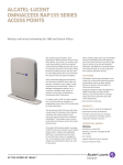
OmniAccess 4324
TM
Wireless LAN Switch
Installation Guide
i
OmniAccess 4324: Installation Guide
Copyright
Copyright © 2005 Alcatel Internetworking, Inc. All rights reserved.
Specifications in this manual are subject to change without notice.
Originated in the USA.
Trademarks
AOS-W and Alcatel OmniAccess 4324 are trademarks of Alcatel in the United
States and certain other countries.
Any other trademarks appearing in this manual are owned by their respective
companies.
ii
Part 031640-00
May 2005
Electromagnetic Interference
FCC - Class A
This equipment has been tested and found to comply with the limits for a
Class A digital device, pursuant to Part 15 of the FCC Rules. These limits are
designed to provide reasonable protection against harmful interference when
the equipment is operated in a commercial environment. This equipment
generates, uses, and can radiate radio frequency energy and, if not installed
and used in accordance with the instruction manual, may cause harmful
interference to radio communications. Operation of this equipment in a
residential area is likely to cause harmful interference in which case the user
will be required to correct the interference at their own expense.
Any changes or modifications not expressly approved by the party responsible
for compliance could void the user’s authority to operate this equipment.
This product complies with Part 15 of the FCC Rules. Operation is subject to
the following two conditions: (1) this device may not cause harmful
interference, and (2) this device must accept any interference received,
including interference that may cause undesired operation.
Industry Canada - Class A
This digital apparatus does not exceed the Class A limits for radio noise
emissions from digital apparatus as set out in the interference-causing
equipment standard entitled “Digital Apparatus,” ICES-003 of the Department
of Communications.
Cet appareil numérique respecte les limites de bruits radioélectriques
applicables aux appareils numériques de Classe A prescrites dans la norme
sur le matériel brouilleur: “Appareils Numériques,” NMB-003 édictée par le
ministère des Communications.
VCCI - Class A
CE - Class A
iii
OmniAccess 4324: Installation Guide
Warning—This is a Class A product. In a domestic environment, this product
may cause radio interference in which case the user may be required to take
adequate measures.
EU - Class A
This product complies with EN55022 Class A and EN55024 standards.
Safety
Lithium Battery Notice
This product contains a lithium battery which is replaceable only by a trained
technician.
CAUTION—The lithium battery may explode if it is incorrectly replaced. A trained
technician should replace the battery with only the same or equivalent type
battery recommended by the manufacturer. Dispose of used batteries according
to the manufacturer’s instructions.
Laser Notice
This product uses replaceable laser transceiver modules on some ports.
CLASS 1
LASER PRODUCT
CAUTION—Use of controls or adjustments of performance or procedures other
than those specified in this manual may result in hazardous radiation exposure.
This product complies with 21 CFR Chapter 1, Subchapter J, Part 1040.10, and
IEC 60825-1: 1993, A1: 1997, A2: 2001, IEC 60825-2: 2000.
For continued compliance with the above laser safety standards, only
approved Class 1 modules from our approved vendors should be installed in
the product. See “Approved GBICs” on page 23 for a list of approved modules
and vendors.
iv
Part 031640-00
May 2005
Contents
Preface
Overview of this Manual .
Related Documents . . . .
Text Conventions . . . . . .
Contacting Alcatel . . . . .
.
.
.
.
.
.
.
.
vii
. . . . vii
. . . viii
. . . viii
. . . . ix
To the Network Manager
xi
The Alcatel Wireless LAN Solution xi
Deployment Summary . . . . . . . . xii
Chapter 1
System Overview . . . . . . . . . 1
Features
................ 1
Physical Description . . . . . . . . . . 2
Chapter 2
Installing the Chassis . .
Pre-Installation Checklist .
Precautions . . . . . . . . . . .
Requirements . . . . . . . . .
Rack Mounting Kit . . . .
Selecting a Location . . .
Mounting the Chassis . . .
Connecting Power . . . . . .
Chapter 3
.
.
.
.
.
.
.
.
.
.
.
.
.
.
.
.
.
.
.
.
.
.
.
.
.
.
.
.
.
.
.
.
. 5
. 5
. 6
. 7
. 7
. 8
. 9
12
Verifying the Installation . . . 13
Appendix A
Power Management . . . . . .
15
Appendix B
Ports . . . . . . . . . . . . . . . . . . .
17
Contents
v
OmniAccess 4324 Installation Guide: Installation Guide
FE Network Ports . . . . . . . . . . .
Serial & Power Over Ethernet .
Physical Description & LEDs. .
Pin Outs . . . . . . . . . . . . . . . .
Cables . . . . . . . . . . . . . . . . .
GE Uplink Ports . . . . . . . . . . . . .
Physical Description and LEDs
Serial Console Port . . . . . . . . . .
Port & Adapter Pin Outs . . . .
Communications Settings . . .
Appendix C
Specifications . . . . . . . . . . . . 27
Notes
vi
Part 031640-00
18
18
18
20
21
22
22
25
25
26
29
May 2005
Preface
This preface includes the following information:
z An overview of the sections in this manual
z A list of related documentation for further reading
z A key to the various text conventions used throughout this
manual
z Alcatel support and service information
Overview of this Manual
This manual is for trained technicians responsible for installing
the OmniAccess 4324 Wireless LAN Switch. This manual is
organized as follows:
Chapter 1, “System Overview”—Describes the main features of
this product, including physical diagrams.
Chapter 2, “Installing the Chassis”—Instructions for mounting the
chassis and attaching power.
Chapter 3, “Verifying the Installation”—Instructions for performing
initial power-on tests.
Appendix A, “Power Management”—Worksheet for determining
system power load.
Appendix B, “Ports”—Describes interface, cable, and adapter
specifications for system ports.
Appendix C, “Specifications”—Describes the system’s size,
weight, storage and operating environment, and certifications
for electromagnetic compliance and safety.
Preface
vii
OmniAccess 4324: Installation Guide
Related Documents
The following items are part of the complete documentation for the Alcatel
system:
z Alcatel Wireless LAN Switch Installation Guide (this manual)
z Alcatel AOS-W User’s Guide
z Alcatel AP Installation Guide
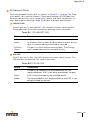
Text Conventions
The following conventions are used throughout this manual to emphasize
important concepts:
TABLE P-1 Text Conventions
Type Style
Description
Italics
This style is used to emphasize important terms and to
mark the titles of books.
System items
This fixed-width font depicts the following:
z Sample screen output
z System prompts
z Filenames, software devices, and certain commands
when mentioned in the text
Commands
In the command examples, this bold font depicts text
that the user must type exactly as shown.
<Arguments>
In the command examples, italicized text within angle
brackets represents items that the user should replace
with information appropriate to their specific situation.
For example:
# send <text message>
In this example, the user would type “send” at the
system prompt exactly as shown, followed by the text of
the message they wish to send. Do not type the angle
brackets.
viii
[ Optional ]
In the command examples, items enclosed in brackets
are optional. Do not type the brackets.
{ Item A | Item B }
In the command examples, items within curled braces
and separated by a vertical bar represent the available
choices. Enter only one choice. Do not type the braces or
bars.
Part 031640-00
May 2005
Contacting Alcatel
Web Site
z Main Site
http://www.alcatel.com
z Support
http://www.alcatel.com/enterprise
Telephone Numbers
z Main US/Canada
(800) 995-2612
z Main Outside US
(818) 880-3500
Preface
ix
OmniAccess 4324: Installation Guide
x
Part 031640-00
May 2005
To the Network Manager
As with any full-featured network equipment, deploying the
Alcatel Wireless LAN (Wireless LAN) solution requires a degree of
planning. The process may involve multiple components as well
as various individuals in your organization. As the network
manager, you should become familiar with the components and
deployment summary outlined in this section.
The Alcatel Wireless LAN Solution
The Alcatel Wireless LAN solution consists of three major
components:
z Alcatel Wireless LAN Switch. This is an enterprise-class
switch into which multiple Access Points (APs) and Air Monitors (AMs) are connected and controlled.
z Alcatel Wireless Access Point. This is a next-generation wireless transceiver which functions as an AP or AM. Although
third-party APs can be used with the Alcatel Wireless LAN
system, the Alcatel AP provides the best features and easiest
integration.
z Alcatel AOS-W Switch Software. This software intelligently
integrates the Wireless LAN switch and APs to provide load
balancing, rate limiting, self healing, authentication, mobility,
security, firewalls, encryption, and centralization for monitoring and upgrades.
To the Network Manager
xi
OmniAccess 4324: Installation Guide
Deployment Summary
This section outlines the various tasks involved in deploying the Alcatel
Wireless LAN solution, and indicates the document where you can find
appropriate instructions.
NOTE—Documents named below are included on the Alcatel Documentation
Library CD-ROM.
1
Physical installation of the Alcatel Wireless LAN Switch
Installation requires a trained technician who is experienced with handling and
installing similar equipment. This phase involves the following tasks:
z Transport, unpack, and mount the switch in a suitable rack environment.
z If using a modular switch chassis, install any extra modules you may have
ordered.
z Attach power and a console.
z Boot the system and perform the initial power-on test, examining the LEDs
and console messages to ensure proper operation.
The Alcatel Wireless LAN Switch Installation Guides provide the necessary
instructions.
2
Initial configuration of the Alcatel Wireless LAN Switch
Configuration requires someone who understands the company's wired
network and has experience with the physical and logical management and
configuration of routers, switches, servers, and clients. This phase involves the
following tasks:
z Use the console to perform initial configuration of the Alcatel Wireless LAN
Switch.
z Attach the switch to the network.
The Alcatel Quick Start Guide provides instructions.
3
Planning the location of access points and air monitors
This phase requires someone familiar with your wireless network deployment
strategy and the features required of the Alcatel Wireless LAN solution. You
can manually determine the locations for APs, or use a Web browser to access
the Alcatel Wireless LAN Switch’s built-in RF Plan tool and perform the
following tasks:
z Define the physical site parameters.
xii
Part 031640-00
May 2005
z Determine how many access points are needed and where they should be
located.
z Simulate network failures and recovery characteristics, and adjust placement if necessary.
Refer to the Alcatel AOS-W User Guide for instructions.
4
Physical installation of the Alcatel Wireless Access Points
This requires a trained technician. The following tasks are involved:
z Perform initial configuration of the AP.
z Mount the AP in its appointed service location.
z Attach required network cables and power.
Refer to the Alcatel AP Installation Guides for instructions.
5
Advanced configuration of the Alcatel Wireless LAN Switch
Again, configuration requires someone who understands the company's
network and has experience managing routers, switches, servers, and clients.
The following tasks are involved:
z Configure the planned network features via command line or Web interface.
z Test and debug the deployment.
Refer to the Alcatel AOS-W User Guide and the Alcatel AOS-W Reference
Guide for in-depth information and examples on the Alcatel Wireless LAN
Switch’s more advanced features.
6
Monitoring and maintenance
This requires someone experienced using various types of software tools to
gather and interpret network performance information. The following tasks
are involved:
z Perform remote monitor and management functions via command line or
Web interface.
z Identify problems and initiate support when necessary.
z Ensure that hardware support issues are handled by a trained technician.
Refer to the Alcatel AOS-W Reference Guide for instructions for collecting
system health and performance information. The Alcatel Wireless LAN Switch
Installation Guides and Alcatel AP Installation Guides provide instructions for
hardware issues.
To the Network Manager
xiii
OmniAccess 4324: Installation Guide
xiv
Part 031640-00
May 2005
CHAPTER 1
System Overview
The OmniAccess 4324 Wireless LAN Switch is an
enterprise-class switch which connects, controls, and
intelligently integrates wireless Access Points (APs) and Air
Monitors (AMs) into the wired LAN.
This chapter introduces you to the Alcatel Wireless LAN Switch. It
describes the general features of the system and illustrates key
physical elements. Once you are familiar with the system, you can
begin the installation process covered in the next chapters.
Features
This section outlines the general features of the Alcatel Wireless
LAN Switch:
z 24 10/100 Mbps Fast Ethernet (FE) ports with Serial and
Power Over Ethernet (SPOE) capability.
z 2 10/100/1000 Mbps Gigabit Ethernet (GE) uplink ports.
z All ports automatically sense and negotiate speed, duplex, and
MDI/MDX settings.
z High-speed Layer-2/Layer-3 packet forwarding.
z High-performance packet processing provides value-added
wireless services such as load balancing, rate limiting,
self-healing, calibration, authentication, mobility, security, firewalls, encryption, and centralized monitoring and configuration.
z 1U chassis can be mounted in a standard 19-inch network
equipment rack.
System Overview
1
OmniAccess 4324: Installation Guide
z The switch firmware can be easily upgraded as future software releases are
made available. You can install upgrades using TFTP.
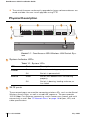
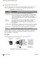
Physical Description
1
5
6
2
3
4
Front View
6
7
Rear View
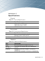
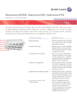
FIGURE 1-1 OmniAccess 4324 Wireless LAN Switch System
1
System Indicator LEDs
TABLE 1-1 System LEDs
LED
State
Description
Power
Green
Switch is receiving proper power.
Off
Switch is powered off.
Green
Switch has booted and is functioning
properly.
Off
Switch is booting, loading software, or
has failed.
Status
2
24 FE ports
These network ports are used for connecting wireless APs, such as the Alcatel
Wireless Access Point, as well as wired LAN segments. The ports provide
10/100 Mbps Fast Ethernet connectivity, and in some cases, power and serial
connectivity as well. See “FE Network Ports” on page 18 for port, LED, and
cable specifications.
2
Part 031640-00
May 2005
Chapter 1
3
2 GE uplink ports
The GE ports can provide high-bandwidth uplinks between the Alcatel
Wireless LAN Switch and the wired LAN. The GE port sockets accept a variety
of Gigabit Interface Converters (GBICs) for versatility in selecting optical and
electrical interfaces. See “GE Uplink Ports” on page 22 for port, LED, and cable
specifications.
4
Serial Console port
This port is for connecting a local management console. It is required to
access the text-based Command-Line Interface (CLI) for initial configuration of
the Alcatel Wireless LAN Switch. It can also be used for switch management
and troubleshooting.
The port accepts an RS-232 serial cable an RJ-45 male connector. See “Serial
Console Port” on page 25 for more port and cable specifications.
See the Alcatel AOS-W User’s Guide for details on using the features available
through this port.
5
Fans/heat exhaust (on side)
Four independent fans promote proper air circulation for cooling the Alcatel
Wireless LAN Switch.
During operation, the air vents on the left and right sides of the chassis must
remain unobstructed by cables or mounting equipment. For proper air
circulation, leave at least 10 cm (4 inches) of clearance on the left and right of
the chassis.
6
Holes for attaching rack mounting brackets (on side)
7
Power Input Socket (on back)
The power input socket on the back of the switch accepts a power cord with
a standard IEC320 connector. For proper safety and performance, the power
cord must be rated to 10 A and conform to grounded electrical standards in
the country where the product is operated.
System Overview
3
OmniAccess 4324: Installation Guide
4
Part 031640-00
May 2005
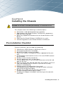
CHAPTER 2
Installing the Chassis
CAUTION—Installation should be performed by a trained technician.
This chapter covers the following installation topics:
z Precautions to be observed during installation
z Requirements for Alcatel Wireless LAN Switch components
and rack mounting gear
z Selecting a proper environment for the Alcatel Wireless LAN
Switch
z Mounting the Alcatel Wireless LAN Switch in a rack
z Connecting power to the Alcatel Wireless LAN Switch
Pre-Installation Checklist
During installation, you will need the following:
OmniAccess 4324 Wireless LAN Switch chassis
Two mounting brackets (included)
Six 6-32 flat head screws (included)
Four 12-24 screws (included) or screws appropriate for your
rack
Alcatel power cord rated to at least 10 A with IEC320 connector (included)
Phillips or cross-head screwdriver
19-inch equipment rack, or equivalent
1U rack space with 10 cm (4 inches) clearance to the left and
right of the rack
Electrical power: 90~135/180~264 VAC, 50 to 60 Hz, 4.0/2.0 A
Cool, non-condensing air 0 to 40 ºC (32 to 104 ºF). May
require air conditioning
Another person to help position the switch
Console terminal (or computer running emulation software)
with RJ-45 or DB-9 serial port
RS-232 serial cable with RJ-45 male connectors
(straight-through Ethernet patch cable)
Alcatel serial adapter (included) if connecting to the console
with DB-9
Installing the Chassis
5
OmniAccess 4324: Installation Guide
Precautions
CAUTION—Hazardous energy is always present while the OmniAccess
4324 Wireless LAN Switch is plugged into an electrical outlet. Remove
all rings, jewelry, and other potentially conductive material before
working with this product.
Never insert foreign objects into the chassis or any other component,
even when the Alcatel Wireless LAN Switch is unpowered or
unplugged.
Main power is fully disconnected from the Alcatel Wireless LAN
Switch by unplugging the power cord from the power outlet. For
safety reasons, verify the power outlet and plug are within easy reach
of the operator.
Do not handle electrical cables which are not insulated. This includes
any network cables.
To minimize electrical hazard, keep water and other fluids away from
the product.
Comply with electrical grounding standards during all phases of
installation and operation of the product. Do not allow the Alcatel
Wireless LAN Switch chassis, network ports, power source, or
mounting brackets to contact any device, cable, object, or person
attached to a different electrical ground. Also, never connect the
device to external storm grounding sources.
Installation or removal of the chassis must be performed in a
static-free environment. The proper use of anti-static body straps and
mats is strongly recommended.
Do not ship or store this product near strong electromagnetic,
electrostatic, magnetic, or radioactive fields.
Do not disassemble the chassis. This product has no internal
user-serviceable parts. When service or repair is needed, see
“Contacting Alcatel” on page ix.
6
Part 031640-00
May 2005
Chapter 2
Requirements
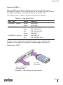
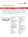
Rack Mounting Kit
Using the included rack mounting kit, you can mount the Alcatel Wireless LAN
Switch in a standard 19-inch network equipment rack. The rack mounting kit
contains the following parts:
6-32 Flat Head
Screws
x 6
12-24 Screws
Left
Bracket
Right
Bracket
x 4
FIGURE 2-1 Rack Mounting Kit
NOTE—The four 12-24 screws are intended for securing the switch to the rack.
Some racks require different screws which are not included. Verify that you
have the correct screws or fasteners for your rack system before attempting
to mount the switch.
Installing the Chassis
7
OmniAccess 4324: Installation Guide
Selecting a Location
The Alcatel Wireless LAN Switch, like other network and computing devices,
requires an “electronics friendly” environment.
z Reliable power
Verify that your electrical outlet is compatible with the Alcatel Wireless LAN
Switch. The switch power input is auto-ranging and accepts 90~132/180~264
VAC, 50 to 60 Hz, 4.0/2.0 A.
The power cords must be rated to 10 A and conform to grounded electrical
standards in the country where the product is operated.
Use of a power line conditioner or Uninterruptible Power Supply (UPS) can
decrease or mitigate problems caused by power service fluctuations. Verify that
the output of any power shaping device is compatible with the Alcatel Wireless
LAN Switch power supply.
z Cool, non-condensing ventilation
For proper operation, the Alcatel Wireless LAN Switch requires an environment
with an ambient air temperature between 0 and 40 ºC (32 to 104 ºF). Humidity
must be kept at non-condensing levels between 5 and 95%.
Where a large number of electrical devices are working in the same area,
additional air conditioning or air circulation equipment may be required.
z Ample space
For proper air circulation, leave at least 10 cm (4 inches) clearance for the vents
on the left and right of the chassis.
Leave additional space in front and back of the chassis to access power cords,
network cables, and indicator LEDs.
z Limited electromagnetic interference
For best operation, keep the Alcatel Wireless LAN Switch and all cords and
cables at least 0.7 meters (2 feet) from fluorescent lighting fixtures, and 2
meters (6 feet) from photocopiers, radio transmitters, electric generators, and
other sources of strong electromagnetic interference.
8
Part 031640-00
May 2005
Chapter 2
Mounting the Chassis
1
Verify that your rack environment meets requirements (see
“Selecting a Location” on page 8).
2
Attach the rack mounting brackets to the switch chassis as
shown in Figure 2-2.
x 6
6-32
flat head
screws
FIGURE 2-2 Attaching the Rack Mounting Brackets
Orient both brackets so that the narrow flange faces the front. When placed
properly, the brackets’ screw holes will match the holes on the side of the
chassis.
Use a Phillips or cross-head screwdriver to attach each bracket securely with
three 6-32 flat head screws (included).
Installing the Chassis
9
OmniAccess 4324: Installation Guide
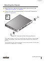
3
Attach the Alcatel Wireless LAN Switch to the rack.
CAUTION—To avoid personal injury or damage to equipment, get help
for lifting and positioning the Alcatel Wireless LAN Switch. Also, do
not install the Alcatel Wireless LAN Switch in any fashion where
instability or uneven mechanical loading may occur.
NOTE—For proper operation, the Alcatel Wireless LAN Switch requires an ambient air temperature between 0 to 40 ºC (32 to 104 ºF). Verify that your rack
environment is in compliance.
Position the switch chassis in the equipment rack and align the brackets’
mounting holes with the corresponding holes in your rack frame.
x 4
12-24
screws
FIGURE 2-3 Mounting the Alcatel Wireless LAN Switch
Use a Phillips or cross-head screwdriver to secure the switch to the rack with
two 12-24 screws (included) for each mounting bracket.
10
Part 031640-00
May 2005
Chapter 2
NOTE—Some cabinets require different screws which are not included. Verify
that you use the correct screws or fasteners for your rack system.
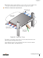
4
Adhere to clearance requirements.
10
Keep Clear for
Air Intake
m
c
Keep Open
to Access
cm
10
Keep Clear
for Air Exhaust
Keep Open
to Access
FIGURE 2-4 “Keep Clear” Zones
For proper air circulation, leave at least 10 cm (4 inches) clearance for the
vents on the left and right of the chassis.
Leave additional space in front and back of the chassis to access power
cords, network cables, and indicator LEDs.
Installing the Chassis
11
OmniAccess 4324: Installation Guide
Connecting Power
CAUTION—This procedure should be performed by a trained technician.
1
Verify you understand the procedure and all precautions.
Before beginning, read the entire procedure. Verify you understand all the
precautions in these steps as well as those on page 6.
2
Verify that your site’s electrical system is compatible with the
switch.
The switch power input is auto-ranging and accepts 90~132/180~264 VAC, 50
to 60 Hz, 4.0/2.0 A.
NOTE—Use of a power line conditioner or Uninterruptible Power Supply (UPS)
can decrease or mitigate problems caused by power service fluctuations. Verify that the output of any power shaping device is compatible with the Alcatel
Wireless LAN Switch power supplies.
3
Verify that the switch power supply can handle the POE devices.
The total power drawn by all connected Power Over Ethernet (POE) devices
must not exceed 200 W total. For details, see “POE Power Requirements” on
page 15.
4
Attach the power cord to the power input socket at the back of
the switch.
Plug an appropriate power cord into the power input socket. Use the included
power cord if it is compatible with your electrical outlet. Otherwise, replace the
power cord with the type appropriate for your country. The power input socket
accepts a power cord with a standard IEC320 connector.
CAUTION—For proper safety and performance, the power cord must be
rated to 10 A and conform to grounded electrical standards in the
country where the product is operated.
5
Attach the power cord to a proper electrical outlet.
Once power is connected, the switch will automatically turn on and you can
perform the power-on test (see page 13).
12
Part 031640-00
May 2005
CHAPTER 3
Verifying the Installation
Once the Alcatel Wireless LAN Switch is physically installed, run
the following power-on test:
1
Check for the proper power indicators.
Immediately upon power up, you should observe the following:
z The system Power LED lights solid green
z The system Status LED is initially off while booting
2
Check the fans to verify they are working.
You should be able to feel significant airflow blowing from the
chassis vents at each of the three fan positions.
CAUTION—If one or more fans do not work, immediately shut down
and replace the Alcatel Wireless LAN Switch.
3
Check for the appropriate operation indicators.
Once the system has successfully booted, you should observe
the following:
z The system Power LED is still lit solid green.
z The system Status LED is solid green.
NOTE—For more information on LED behavior, see System Indicator LEDs on page 2.
Verifying the Installation
13
OmniAccess 4324: Installation Guide
4
Once the system has passed the initial power-up test:
z Connect appropriate network cables (see Appendix B on page 13 for port
and cable information).
5
14
You are now ready to perform the initial setup as described in the Alcatel Quick
Start Guide (which is included in the Accessory Kit).
Part 031640-00
May 2005
APPENDIX A
Power Management
Use this worksheet to determine the power required by your
Alcatel Wireless LAN Switch. Use a separate copy for each
system deployed in your network.
System and Location
Name of Alcatel Wireless LAN Switch
Location
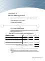
POE Power Requirements
Determine the power output required by switch ports that supply
Power Over Ethernet (POE).
TABLE A-1 OmniAccess 4324 Power Requirements
Power
Rating
x
Number
Power
=
of Units
Subtotal
Each Alcatel AP drawing POE
10 W
x
=
Each Cisco 1200 AP drawing POE
12 W
x
=
W
x
=
Component Name
Each other Access Point drawing POE
Total POE power required in Watts:
Make sure that the total POE power required does not exceed
200 W.
NOTE—Recalculate the worksheet numbers whenever devices
using POE are connected to or disconnected from the network
ports.
Power Management
15
OmniAccess 4324: Installation Guide
16
Part 031640-00
May 2005
APPENDIX B
Ports
The OmniAccess 4324 Wireless LAN Switch has a number of
ports, each with their own purpose:
z 24 Fast Ethernet (FE) ports
Used for connecting to Access Points (APs) and wired LAN
segments. These 10/100 Mbps FE ports aggregate and route
traffic under the direction of the switch’s internal software. These
ports can also provide power and serial connectivity to compatible
devices.
z 2 Gigabit Ethernet (GE) ports
Used for high-bandwidth 10/100/1000 Mbps GE uplink between
the Alcatel Wireless LAN Switch and the wired LAN. Each port
socket accepts a variety of Gigabit Interface Converters (GBICs)
for versatility in selecting optical and electrical interfaces.
z One Serial Console port
Used for connecting a local configuration and management
console.
This chapter describes the general features and physical
characteristics of the various ports and details their compatible
cables and connectors.
Ports
17
OmniAccess 4324: Installation Guide
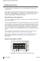
FE Network Ports
The Alcatel Wireless LAN Switch has 24 10/100 Mbps Fast Ethernet (FE)
network ports.
The FE ports are used for connecting the switch to wireless Access Points
(APs) and wired LAN segments. These ports can also provide power and serial
connectivity to compatible devices. All FE ports automatically sense and
negotiate speed, duplex, and MDI/MDX settings.
Serial & Power Over Ethernet
Each FE port supports RS-232 Serial communications and IEEE 802.3af Power
Over Ethernet (SPOE).
When a compatible Power Over Ethernet (POE) device (such as the Alcatel AP)
is connected to a network port, the port can provide operating power to that
device through the connected Ethernet cable. This allows APs to be installed in
areas where electrical outlets are unavailable, undesirable, or not permitted,
such as in the plenum and air handling spaces. The switch network ports
automatically detect when compatible POE devices are connected and require
power.
The network ports also provide serial connectivity over the same Ethernet
cable, allowing convenient access to device console interfaces.
Special cables and adapters may be necessary to use SPOE features with
some equipment. See material starting on page 20 for port and cable
specifications.
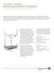
Physical Description & LEDs
0
2
LNK/ 1 POE
ACT
1
4
3
A
5
B
6
ACCESS
POINT
STATUS
0
4
1
5
2
6
3
7
7
2
FIGURE B-1 OmniAccess 4324 FE Network Ports
18
Part 031640-00
May 2005
Appendix B
1
FE Network Ports
Ports are grouped in banks of 8 (as shown in Figure B-1 on page 18). There
are 3 banks, for a total of 24 ports. These ports provide 10/100 Mbps Fast
Ethernet connectivity, and in some cases, power and serial connectivity as
well. See material starting on page 20 for port and cable specifications.
A
LNK/ACT LED
Each FE port has its own LNK/ACT LED, located at the left side of the port.
During operation, these LEDs provide the following status information:
TABLE B-1 FE LNK/ACT LED
B
Status
Description
Off
No Ethernet link on the port.
Green
An Ethernet link has been established on the port, but no
data is currently being transmitted or received.
Flashing
Green
The port is transmitting or receiving data. The flashing
rate is proportional to your network activity.
POE LED
Each FE port has its own POE LED, located at the right side of the port. This
LED provides the following POE status information:
TABLE B-2 FE POE LED
Status
Description
Off
The port is disabled or the attached device has not
requested power. POE is not being provided by the port.
Green
POE is being provided to the attached device.
Amber
The attached device has requested power, but POE is not
being provided by the port.
Ports
19
OmniAccess 4324: Installation Guide
2
Access Point Status LEDs
Each LED represents the status of APs connected to a specific port on the
switch. During operation, the LEDs provide the following information:
TABLE B-3 AP Status LED
Status
Description
Red (solid)
An AP on this port has failed (highest precedence).
Red (flashing) An air monitor on this port has detected an unsecured AP.
The AP is attached to your network but is not listed in the
switch security policies. If security policies are enabled,
clients are not granted access to your network through the
unsecured AP.
Green
(flashing)
An air monitor on this port has detected interference. The
interfering device (AP or other radio source) has been
detected by your valid APs, but has no wired presence on
your network.
Amber (solid)
Load balancing is enabled on this port or an AP has reached
the maximum number of clients it is configured to support.
Green (solid)
All detected APs on this port are operating as expected.
Off
No AP is detected on the port (lowest precedence).
The LED states in Table B-3 are listed in order of precedence (highest to
lowest). If more than one AP is connected to the port, the state with the
highest precedence is displayed.
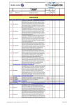
Pin Outs
The RJ-45 female connector pin-outs are shown in Figure B-2 :
10/100 Mbps
Ethernet
LNK/
ACT
POE
RJ-45 Female
Pin-Out
1
2
3
4
5
6
7
8
Direction
Input
Output
ETH Rx+
(POE negative*)
ETH Rx–
(POE negative*)
ETH Tx+
(POE positive*)
Serial TxD**
(POE positive*)
Serial TGND** (POE positive*)
ETH Tx–
(POE positive*)
Serial RxD**
(POE negative*)
Serial RGND** (POE negative*)
*POE optional
**Serial optional
FIGURE B-2 FE Network Port Pin-outs
20
Part 031640-00
May 2005
Appendix B
Cables
The type of cable required for each port depends on the device being
connected:
z Direct connection to a SPOE compatible device.
This requires an 8-conductor Category 5 UTP Ethernet cable with an RJ-45
male connector. A straight-through cable is required to preserve POE voltage
polarity.
The port should be connected to the intended device either directly or using a
SPOE adapter with no intervening hubs, routers, switches, or other network
equipment.
Alcatel SPOE adapters separate the serial and FE portions of the cable and
route them to their individual ports on the connected device. There are two
adapter models:
z
CA-SPOE-ADAPT-1 adapts the Ethernet cable for DB-9 serial and RJ-45
FE devices.
z
CA-SPOE-ADAPT-2 adapts the Ethernet cable for RJ-45 serial and
RJ-45 FE devices.
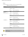
The Alcatel SPOE adapters are compatible with the following APs:
TABLE B-4 Alcatel SPOE Adapter Compatibility
AP Make and Model
POE
Serial
Yes
Yes
CA-SPOE-ADAPT-1
Cisco 340
No
Yes
CA-SPOE-ADAPT-1
Cisco 350
Yes
Yes
CA-SPOE-ADAPT-1
Cisco 1100
Yes
No
CA-SPOE-ADAPT-1
Cisco 1200
Yes
Yes
CA-SPOE-ADAPT-2
SMC EZ Connect
2755W
No
Yes
CA-SPOE-ADAPT-1
Alcatel APs
Alcatel SPOE Adapter
z Direct connection to a POE compatible device.
This requires a 4- or 8-conductor Category 5 UTP Ethernet cable with an RJ-45
male connector. A straight-through cable is required to preserve POE voltage
polarity.
For POE, the port should be connected directly to the intended device with no
intervening hubs, routers, switches, or other network equipment.
z Connection to a regular 10/100 Mbps Ethernet segment
This requires a 4- or 8-conductor Category 5 UTP Ethernet cable with an RJ-45
male connector. The port detects MDI/MDX and automatically adjusts for
straight-through or crossover cables.
The maximum length for FE cables is 100 meters (325 feet).
Ports
21
OmniAccess 4324: Installation Guide
For cables that run through plenums or air-handling spaces as described in
NEC (2002) Article 300.22(C), the cable should be suitable under NEC Article
800.50 and marked accordingly for use in plenums and air-handling spaces
with regard to smoke propagation, such as CL2-P, CL3-P, MPP or CMP.
Be sure to install cables in accordance with all applicable local regulations and
practices.
GE Uplink Ports
The switch has two Gigabit Ethernet (GE) uplink ports. These ports provide
high-bandwidth 10/100/1000 Mbps Gigabit Ethernet uplinks between the
Alcatel Wireless LAN Switch and the wired LAN. The port automatically senses
and negotiates speed, duplex, and MDI/MDX settings.
Physical Description and LEDs
LNK/
ACT
24
LNK/
ACT
25
FIGURE B-3 GE Uplink Ports
Each GE port socket accepts a variety of Gigabit Interface Converters (GBICs)
for versatility in selecting optical and electrical interfaces.
Each GE port has its own LNK/ACT LED, located to the right of the port. During
operation, these LEDs provide the following status information:
TABLE B-5 GE LNK/ACT LED
22
Status
Description
Off
No Ethernet link on the port.
Green
An Ethernet link has been established on the port, but no
data is currently being transmitted or received.
Flashing
Green
The port is transmitting or receiving data. The flashing rate is
proportional to your network activity.
Part 031640-00
May 2005
Appendix B
Approved GBICs
Approved GBICs are typically selected when the line card is purchased.
Although the modules are user-replaceable, for continued safety and reliability
only approved modules from approved vendors should be used.
The following Class 1 GBICs have been tested with this product:
TABLE 3-1 Approved GBICs
GBIC Type
Vendor
Module ID
1000BASE-T (copper)
Alcatel
OWA-GBIC-T
Molex
74740-0001
Alcatel
OWA-GBIC-SX
Delta
GBIC-1250A3FS
OCP
DTR-1250-MM-GB
Agilent
HFBR-5601
Alcatel
OWA-GBIC-LX
OCP
DTR-1250-SM-GB-L1
1000BASE-SX (optical)
1000BASE-LX (optical)
For more current information on modules of other types and from other
vendors, visit our Web site or contact customer support (see page xiii).
Replacing a GBIC
Insert GBIC
With Label Up
Squeeze Release Tabs
and Remove GBIC
FIGURE 3-1 GBIC Removal and Insertion
Ports
23
OmniAccess 4324: Installation Guide
Cables
The following table lists the cable characteristics for approved GBICs:
TABLE 3-2 GE Cable Characteristics
GBIC Type
Characteristics
1000BASE-T (copper)
Cable:
Category 5 UTP
Connect
or:
RJ-45
Up to 100 m (325 feet)
Range:
1000BASE-SX
(optical)
Shortwave 850 nm
Cable:
62.5 µm multimode fiber
Connect
or:
SC-type fiber optic
Up to 260 m (850 feet)
Range:
Cable:
50 µm multimode fiber
Connect
or:
SC-type fiber optic
Up to 550 m (1800 feet)
Range:
1000BASE-LX
Cable:
9-10 µm singlemode fiber
Connect
or:
SC-type fiber optic
Up to 10km (6.21 miles)
Range:
Cable:
62.5 µm multimode fiber
Connect
or:
SC-type fiber optic
Up to 550 m (1800 feet)
Range:
CAUTION—Be sure to follow the instructions and notifications in “Laser
Notice” on page iv.
24
Part 031640-00
May 2005
Appendix B
Serial Console Port
The serial console port is located on the front panel of the Alcatel Wireless
LAN Switch. This port is for connecting a local management console and can
be used to access the text-based Command-Line Interface (CLI) to configure,
manage, and troubleshoot the Alcatel Wireless LAN Switch.
CAUTION—Do not connect Access Points to the serial console port.
The serial port is designed to connect to RS-232-only devices.
Non-RS-232 devices such as Access Points will cause the Switch to
fail and can cause damage.
See the Alcatel AOS-W User’s Guide for using the features available through
this port.
Port & Adapter Pin Outs
The serial console port’s RJ-45 female connector accepts an RS-232 serial
cable with a male connector. Pin-outs are shown in Figure B-4 :
Serial
Console Port
RJ-45 Female
Pin-Out
1
2
3
4
5
6
7
8
Direction
Input
Output
TxD
TGND
RGND
RxD
FIGURE B-4 Serial Port
To connect the required RS-232 serial cable to a terminal with a DB-9 male
port, use the included adapter. Pin-outs are shown in Figure B-5 :
RJ-45 Female
Pin-Out
1
2
3
TxD
4
TGND
5
RGND
6
RxD
7
8
Direction
Input
Output
Internal
Connections
RJ-45
TxD
3
4
GND
5
RxD
6
DB-9 Female
Pin-Out
DB-9
2
5
3
9
8
7
6
5
4
3
2
1
Ground
RxD
TxD
Direction
Input
Output
FIGURE B-5 Serial Port Adapter
Ports
25
OmniAccess 4324: Installation Guide
Communications Settings
TABLE B-6 Console Terminal Settings
26
Baud Rate
Data Bits
Parity
Stop Bits
Flow Control
9600
8
None
1
None
Part 031640-00
May 2005
APPENDIX C
Specifications
Physical
TABLE C-1 Physical Specifications
Item
Specification
Size
Height 4.45 cm (1.75 inches)
Width 44.2 cm (17.4 inches)
Depth 40.9 cm(16.1 inches)
Weight
5.7 KG (12 lbs.)
Environment
TABLE C-2 Environmental Specifications
Item
Specification
Temperature
Operating: 0 to 40 ºC (32 to 104 ºF)
Storage: 0 to 50 ºC (32 to 122 ºF)
Humidity
5% to 95% (non-condensing)
Operation
TABLE C-3 Operational Specifications
Item
Specification
Power
90~132/180~264 VAC, 50-60 Hz, 4.0/2.0 A
Network
Management
Command-Line Interface and HTML Web-browser
Interface
Standards
IEEE 802.1x, IEEE 802.3 10BASE-T, IEEE 802.3u
100BASE-TX,
IEEE 802.3ab 1000BASE-T, IEEE 802.3z 1000BASE-SX
Specifications
27
OmniAccess 4324: Installation Guide
Certifications
TABLE C-4 Certifications
Item
Specification
Electromagnetic
Compatibility
FCC Part 15 Class A CE
ICES-003 Class A
VCCI Class A (Japan)
The CE approval mark on back of the
product indicates that it meets
European Directive 89/336/EEC
EN 55022 Class A (CISPR 22 Class A), EN55024,
EN 61000-3-2, EN 61000-3-3
AS/NZS 3548 Class A
Safety
UL60950,
CAN/CSA C22.2 No 60950,
IEC/EN60950
Low Voltage Directive (LVD) 73/23/EEC
21 CFR Chapter 1, Subchapter J, Part 1040.10 (Laser
Safety),
IEC/EN 60825-1, EN 60825-2 (Laser Safety)
28
Part 031640-00
May 2005
Notes
Notes
29
OmniAccess 4324: Installation Guide
30
Part 031640-00
May 2005