1
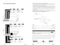
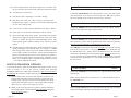
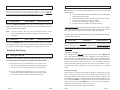
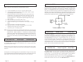
V 8.3
pcbv7.3/8.1
AutoCommand®
“Add-On”
Remote Control Car Starter
Model 20022
Installation Manual
For use on automatic vehicles only.
For gasoline or diesel vehicles.
7955 Cameron Brown Court
Springfield, Virginia 22153 USA
www:designtech-intl.com
20022
Page 1
LIMITED WARRANTY
Congratulations on your purchase of the AutoCommand® Remote Car Starter. The
AutoCommand® Remote Car Starter system allows you to start the car by remote
control from the comfort of your home or office in order to cool it down in the
summer or heat it up in the winter.
DesignTech International, Inc. Warrants to the original consumer/purchaser that this product
shall be free of defects in material and workmanship under normal use and circumstances for a
period of two (2) years from the date of original purchase for use. When the original
consumer/purchaser returns the product to DesignTech International Inc., 7955 Cameron Brown
Court, Springfield, Virginia 22153, USA within the warranty period, and if the product is
defective DesignTech International, Inc. will at its option repair or replace such.
This model 20022 is an “add-on” unit and must be used in conjunction with
another remote control unit such as a remote car alarm or keyless entry
system.
This warranty shall constitute the sole liability of DesignTech International, Inc. concerning
the product. DesignTech International, Inc. expressly disclaims all other warranties INCLUDING, WITHOUT LIMITATION, THE WARRANTIES OF MERCHANT ABILITY AND FITNESS FOR A PARTICULAR PURPOSE. NO PERSON, FIRM , OR CORPORATION IS AUTHORIZED TO ASSUME FOR DESIGNTECH INTERNATIONAL, INC. ANY OTHER LIABILITY IN CONNECTION WITH THE SALE AND USE OF THE PRODUCT. DesignTech
International, Inc. and agents and distributors will bear no liability whatsoever for incidental or
consequential damages or charges of any kind.
AutoCommand® is for automatic transmission cars only. It is an extremely sophisticated system with multiple built-in safety and security features.
Some states do not allow the exclusion or limitation of incidental or consequential damages, so
the above disclaimer regarding incidental or consequential damages may not apply to you.
The AutoCommand® Remote Car Starter:
•
Will start your car by remote control, and run the heater, defroster, or air
conditioner to warm up or cool down the car.
•
Is designed to start the car if it is in park, and only if the hood is closed.
•
Can monitor the engine’s speed using a special tachometer monitoring circuit.
•
Will attempt to start the car for up to six seconds, but no longer (to avoid
damage to the starter motor). Should the car not start, or if it stalls after
starting, the AutoCommand® will make 2 further attempts to start it.
•
Will not let the car be driven without the key in the ignition.
•
Shuts itself off automatically after 10 or 15 minutes (user selectable) if you
forget to come out to your car.
•
Will shut off if the brake pedal is pushed, the hood is opened, or the transmission is shifted out of park - unless the key is in the ignition and in the
“run” position.
This warranty is void if the product or has been damaged or tampered with or if the product or
any such parts have been opened. In all cases of damage during shipment, a claim must be filed
with the shipping carrier and not with DesignTech International, Inc.
This warranty gives you specific legal rights; you may also have other rights which vary from
state to state.
OUT OF WARRANTY REPAIRS
DesignTech International, Inc. will at its option either (1) replace this product with a functionally similar (but not necessarily visually identical) refurbished product or (2) repair the original
product and return it to the original consumer/purchaser C.O.D. covering all reasonable repair or
replacement charges if the product is returned prepaid to DesignTech International, Inc., 7955
Cameron Brown Court, Springfield, VIRGINIA 22153, USA, after the two year warranty period
has expired.
__________________________________________________________________________
This registration card must be returned within ten (10) days of purchase.
NAME_________________________________________________________ User's Age______________
ADDRESS____________________________________________________________________________
•
Allows you to remove the key while leaving the car running with the doors
locked for up to 10 or 15 minutes utilizing the QUICK STOPTM option.
•
Starts the car automatically should the temperature drop below 0°F (-18’C),
or if the battery voltage drops below 11 volts with the VACATION TM option.
•
This warranty shall be effective only if the registration card is fully completed and mailed with
proof of purchase to: DesignTech International, Inc., 7955 Cameron Brown Court, Springfield,
Virginia 22153, USA within ten (10) days after date of purchase.
Is quality engineered, microprocessor controlled, and made in the USA to
provide many years of reliable use.
_____________________________________________________________________________________
City
State
Zip
PLACE OF PURCHASE_____________________________________DATE OF PURHASE____________
Product Purchased:
Purchased for :
AutoCommand #20022
________YOURSELF
_________SPOUSE
________OTHER FAMILY MEMBER
_________FRIEND
Where did you learn about this product?____________________________________________
Vehicle Make:__________________Vehicle Model:________________Year:_____ _________
___________Please send me FREE information on other innovative DesignTech products.
DesignTech International, Inc.
7955 Cameron Brown Court, Springfield, Virginia 22153, USA
Tel: (703) 866-2000
Fax: (703)866-2001
v8.3
Page 2
20022
20022
Page 19
Important Note:
Make sure that all drivers who will be operating the AutoCommand® are fully
aware of the safety precautions installed and their limitations. Stress the importance of switching the On/Off control switch to the “OFF” position (down)
every time the car is serviced. Show the user how the control switch must be
turned off and on again after pulling out the key before leaving the car. Give the
user a copy of the tan colored page - USER TIPS AND NOTES so that they can
familiarize themselves with the product.
!! WARNING !!
Do not connect this AutoCommand® to a manual transmission vehicle.
Doing so could cause serious property damage, personal injury, and will
void all warranties.
Tools required to install the AutoCommand® unit:
USER INFORMATION:
Wire cutters/strippers
Soldering iron
The brown USER TIPS & NOTES sheet gives you further detail regarding
daily use of this product. Any modifications not expressly approved by DesignTech will void the user’s authority to operate the equipment.
Pliers
Screwdrivers
OTHER ACCESSORIES
The following installation accessories are available through your dealer or DesignTech. All prices are in US dollars. Shipping and handling costs are included.
#20041
#20043
#20049
VATS kit
(to work with the GM PASS key system)
Bosch 30 amp relays
Wire harness for above relay
$14.95
Test meter
Drill and 1/2” bit
We highly recommend that all connections be soldered for reliability.
Parts list
$9.95
$9.95
AutoCommand® module
Baggie of Parts
Control harness (10 position)
6 Power & Ignition wires
Please have model number and diagnostic code ready
before calling tech support
Parts kit in plastic baggy:
7955 Cameron Brown Ct; Springfield, Virginia 22153 USA
Tel: (703)866-2000 or (800)337-4468
www:designtech-intl.com
Page 18
20022
20022
30 A Fuse
3 Tab connectors
On/Off control switch
Warning Label
Window decal
Ring terminal
Hood pin switch set
2 cable ties (not pictured)
Page 3
1. Remove the top and bottom halves of the steering column shroud.
2. Locate the small three wire harness (with White, Black and Yellow wires) running down from the
ignition key cylinder on the top right hand side of the steering column into the instrument panel.
3. Cut the Yellow wire in half and bare back the Black wire.
4. With the ignition key in and turned to the “ON” or “RUN” position, measure the resistance between the key side of the Yellow wire and the Black wire. Make several measurements to verify
that you have a consistent resistance. You also need to change your test leads around. You will find
that you get two different readings. So far we have found that the higher of the two readings is the
correct resistance.
5. When you have correctly identified the correct resistance obtain a resistance of the same value.
6. Locate the Black “Bulb Test” wire on the left side of the steering column in cavity “D” or “E” of
the Black 5-way connector, just above the main ignition switch connector.
7. Wire the relay as shown in the following Diagram.
AutoCommand Model 20022
Color
Pink
White
Yellow
Blue
Green
Black
Function
Power(+12V)
Accessory/Lights
Starter
Ignition 1
Ignition 2
Ground
Color
Yellow/Green
Green/White
Brown
Brown/White
Gray/Black
Left White Button
Type
Input
Relay output
Relay output
Relay output
Relay output
Input
Function
Alarm Control
Sensor IN
Accessory Pulse
Alarm Disable
Sensor OUT
Required
Yes
Yes
Yes
Yes
Maybe
Yes
Type
Required
(+) 400 mA
No
Relay
No
(-) 400 mA
No
(-) 400mA
No
Relay
No
4) New GM PASSLOCK® II Anti-Theft System for 1998 model
vehicles. In 1997 the Malibu/Cutlass and then in 1998 all truck platforms (Full size
Right Red Button
Pickup, Suburban, S-10/Sonoma, Blazer/Jimmy, Tahoe/Yukon and Astro/Safari) came out
with this new Passlock II system.
Use the diagram above and the list below to interface to this new type system. Note that the
Yellow wire for the Passlock is a similar gauge wire to the Starter wire. Don’t confuse these.
LED
Plug-in Control Switch
Color
Red/Black
Red/White
Green
Violet
Orange
Page 4
Function
Type
Control Switch
Remote
- Input
Tach
Input
Hood
- Input
Brake
+ Input
You must acquire a resistor value within 5% of the value of the resistor in the key. Additionally, there is No BULB TEST wire on this system, so pin 87 is not used.
Required
Yes
Yes
No
Yes
Yes
Substitute as follows:
Wire color above
‘Black or Yellow’
‘Black’
‘Black/White or White’
20022
20022
Trucks
Yellow
Orange/Black
Red/White
Malibu / Clutlass
Yellow
Black
Red/White
Page 17
Most of the 1990-1995 Cadillacs have a slight variation on the wiring for the VATS
system. On these cars, there is an ORANGE wire (actually a vinyl sleeve) that contains
smaller wires. This is located underneath the steering column next to the YELLOW
sleeve that is labeled “Air bag wiring” -- do not cut this Yellow sleeve. Slit the ORANGE
sleeve open to expose two pairs of wires which are either both white, OR both yellow,
OR both black.
Note:
When installing a GM vehicle with a VATS bypass system, the GREEN
IGN 2 wire must only go to the VATS relay. If you need IGN2 in the car,
simply supply power to the IGN2 wire of the vehicle by jumping power from
the BLUE IGN1 wire. (Thus BLUE will be powering up 2 wires behind the
key -- and in some cases 3 wires).
2) Diesel Vehicles:
You must hook the RED/BLACK wire up to the diesel
glow-plug light wire or to the positive side of the vlow plugs itself as described in
STEP 18.
The following chart outlines the options that need to be set for diesel vehicles. (Use
the Chrysler settings for all other diesel vehicles.)
Option
3
4
Ext. Crank Super Crank
Chrysler
X
Ford
X
Chevrolet X
X
5
IgnoreMeter
X
X
6
Diesel
X
X
X
!! WARNING !!
On cars with airbags, you may notice bright yellow tubes or harnesses underneath the steering column area. DO NOT tamper with these wires in any way,
so as to prevent personal injury and/or damage to the air bag system.
Battery gases are explosive. Do not smoke while working near the car’s battery.
!!CAUTION!!
When working the wires through the car’s firewall, be sure to protect them
from sharp metal edges and from hot surfaces on the engine.
Note: Some installers connect a battery charger to the vehicle’s battery during installation. This is fine, but it must be removed before running the vehicle under AutoCommand® control.
INSTALLATION INSTRUCTIONS
1. Before You Start
Take the time to read through the whole installation manual.
3) General Motors Passlock™ Security System Bypass
New GM PASSLOCK® Anti-Theft System for 1995 through 1997 models
Beginning in 1995 and 1996 GM introduced a new version of their old VATS
security system. This new PASSLOCK® system will only be found in the 1995
Chevrolet Z24 Cavalier, Pontiac Sunfire GT only, 1996+ Pontiac Grand Am,
Oldsmobile Achieva, and the Buick Skylark, Chevrolet Cavalier and Pontiac
Sunfire. You can determine if the vehicle is equipped with this system by
checking for a “Security” or “Theft” light on the dash panel. Basically, what
they have done is taken the resistor that was part of the key on the original
VATS and moved it to inside the lock cylinder of the steering column. They
have also set additional parameters to make this even more complicated. To
bypass this system, use the following diagram and instructions. Follow these
instructions very carefully and remember that the resistance must be within 5%
of the correct measured value.
Wire Harnesses: Before installation, always check that your wire
harness matches the list/drawing on page 4 of the manual.
IMPORTANT: After having read the entire manual, start the
installation by putting the yellow WARNING STICKER in the engine compartment. Choose a surface that is clean and readily visible when the hood is
open.
Note that for these vehicles with PASSLOCK, the AutoCommand’s Green Ignition 2 wire goes to the vehicle’s White Ignition wire. The AutoCommand’s
White Accessory wire goes to the Vehicle’s Orange Ignition wire.
Page 16
20022
20022
Page 5
POWER & IGNITION WIRES
C. You can choose the next option by pushing the left button again to
index to the next option. When you get to the next option you
want to change, simply repeat Step B above. After six seconds,
the AutoCommand® automatically exits the programming mode
(Three LED flashes).
The AutoCommand® module will be installed under the dash once all wiring
has been completed. Do not mount the module at this time! You will need
to check the diagnostic light (LED) as the installation progresses. Locate
(or drill) a hole in the firewall to run the VIOLET (hood) and the GREEN
(tach) wires of the Control Harness and the PINK wire of the Power Harness
through into the engine compartment. The remaining short wires stay in the
passenger area. Leave about a foot of the wire harness under the dash for ease
of working and visual access to the diagnostic lights.
SPECIAL CASES
Note:
1) VATS system (for GM cars with special PASS key).
Always connect the Black and Pink wires before connecting
any of the other wires.)
2. Black Wire (14 AWG)
Ground
Connect this BLACK wire to a very good, clean chassis ground in the driver’s
kick panel area. Use the small red ring terminal if needed. The metal bracing
around or beneath the dash board is not adequate.
3. Pink Wire (12 AWG)
Power (+12V)
Plug this wire onto the spade terminal marked Power. Run the other end
of this wire through the firewall of your vehicle and to the positive side of
the vehicle’s battery terminal. Connect the ring terminal of the fuse
holder provided to the vehicle’s positive battery post. Join the remaining
ends of the power wire together by soldering them. Alternatively, you
may wish to use a Yellow butt terminal, but we recommend soldering.
Ignition Key Diagram for Steps 4-7
The vehicle’s wires are found coming off of the key switch.
Lock/Off
ACC
Page 6
ACC
D. Turn the Control Switch back ON and confirm that the LED flashes
once as the switch is turned ON.
If you have a GM vehicle with a factory anti-theft system (a resistor in the key),
you need to follow these directions:
Measure the resistance of the key. It should be between 392 ohms and 11,800
ohms. To do this, put the ohm meter probes on each side of the key pellet.
This value should be close to one of the following (all values in ohms): 392,
523, 681, 887, 1.13K, 1.47K, 1.87K, 3.01K, 3.74K, 4.75K, 6.04K, 7.5K, 9.53K,
11.8K. Purchase a resistor with a value within 5% of this measured value and a
30 amp BOSCH type relay.
Locate the pair of VATS wires (sometimes White/Black striped and Purple/
Black striped) running behind the dash from the passenger side to the driver’s
side behind the key switch. Connect our Ignition 2 (GREEN) wire to pin 86
and ground to pin 85 on the relay. NOTE: You will have to use IGN 1 to power
up all of the Ignition wires behind the key -- since IGN 2 needs to be used here
for the VATS relay. Cut ONE of the VATS wires and connect the key-switch
side to NC pin 87A, and the other side (Engine Side) to common pin 30. Connect
the other VATS wire to NO pin 87 with the selected resistor soldered in line as
shown here:
RUN
START
20022
20022
Page 15
#1 sets the starting method. The factory setting uses “No-Tach” starting. If you wish to use the tach to start, follow the instructions in 12A.
#2 is for the choice of run times.
4 Blue Wire (14 AWG)
Ignition 1
Connect the LIGHT BLUE wire to the ignition 1 wire of your vehicle. This
wire will measure +12V on the test meter in the “run” and “start” position,
and is off (ground) in the “lock/off” and “accessory” positions).
#3 will add 50% more crank time to “No-Tach” starting.
#4 adds 100% more crank time. This is necessary on many deisel
and hard to start vehicles. Options #3 and #4 can be added together
for even more cranking time.
#5 is used in the “No-Tach” starting method for some diesel vehicles.
5. Green (14 AWG)
Ignition 2
Connect the GREEN wire to the second IGN2 wire of your vehicle. This is a
wire that is hot in the “run” and sometimes “start”.
#6 option must be activated when installing on a diesel vehicle.
#7 cancels the Enable mode safety feature. The Enable mode requires
that the driver toggle the ON/OFF control switch “OFF” then “ON”
in order to “enable” the vehicle for AutoCommand® control. This
feature guards against undesired starting of the vehicle by remote
control.
#8 Normal Trigger will start and stop the AutoCommand with a single
quick ground pulse to the Remote Input wire of Step 13. Double
Pulse Trigger mode will not activate the AutoCommand until it has
seen two pulses within 3 seconds time. Thus if you hook the Remote
Input wire up to the Door Lock wire of your keyless entry module -you can lock the doors with just one push of the transmitter’s Lock
button. If you push transmitter’s Lock button again within 3 seconds
-- you will lock AND start the vehicle.
6. White Wire (14 AWG)
Accessory / Lights
Connect the WHITE wire to the accessory wire which is +12V in the “run”
and “accessory” position, but off (ground) in the “start” and “off” positions.
This wire will power the heater / air conditioner (in some cars).
This WHITE wire can also be used as the headlights wire if you do not need
it for the Accessory position -- or if you power the heater / air conditioner with
the GREEN IGN2 wire. Simply connect this WHITE wire to the low beam
connection of the headlights or to the parking lights. Do not use this wire for
to power both Accessory AND Headlights together unless you use 2 external
relays powered by this WHITE wire -- one for the headlights and the other for
the Accessories.
SETTING PROGRAM OPTIONS:
If you want the factory setting, DO NOTHING and skip this section. If you
want to change to one of the options, TURN THE ON/OFF
CONTROL SWITCH TO THE “OFF” POSITION. Wait for the red LED to
stop flashing, then continue with the following procedures:
A. Push the white button to the left of the red LED. Each time you
push the white button the red LED will flash 1 to 8 times signifying
at which option you are (press it once, the LED flashes once. Press
it again and it will flash two times. Press it again and it will flash
three times, etc., to show what option you are at).
B. When you are at the option level you desire, push the red button
for a second and the red LED will flash once for Option setting and
Twice for Factory setting.
Page 14
20022
7. Yellow (14 AWG)
Starter
Connect the YELLOW wire to the starter wire. This wire is hot in the “start”
position only.
Note: Nissan vehicles have two starter wires. Connect both starter wires to
the YELLOW wire.
8. Control Switch
Plug-in Switch
Plug the Control Switch into the AutoCommand on the side next to the push
buttons and led light. Mount the switch using a 1/2” drill bit.
20022
Page 7
Control Harness (All wires are the smaller 18 AWG size)
9. Violet Wire
20. Trouble Shooting with the Self Diagnostics
Hood Pin Switch Control Harness
The hood pin switch MUST be installed with the AutoCommand®. It
prevents operation of the AutoCommand® when the hood is open. Connect
the VIOLET wire to the hood pin switch
using the red connector.
Note:
If you already have a hood
pin switch which is being
used by a car alarm system, you may share the
wiring -- but be sure
to diode isolate each
wire going to the
hood pin switch
with the bands
of
diodes
pointing towards the
pin switch
as follows:
10. Orange Wire
Brake Shut-off
1 flash
2 flashes
3 flashes
4 flashes
5 flashes
6 flashes
8 flashes
12 flashes
10/15 minute time out -- unit should be fine.
Brake or Hood activated
No Tach or Stalled. Check tach learning. Or confirm that the
alternator is being powered up by one of the ignition wires.
Received another remote input signal.
Transmission was shifted into gear.
Low battery voltage, or may be missing an ignition wire
which powers up the alternator
Over-current. A transistor output is being over driven.
The control switch was turned off.
In order to get an accurate diagnostic, allow the unit to go through its complete
starting cycle(s). The unit may only try to start once or it may try 3 times. In
order to get an accurate reading, please wait 45 seconds after its last attempt to
start.
21. Special Programming Options
Control Harness
The ORANGE 18 gauge wire will disable the AutoCommand® when the brake
pedal is pressed down. This is an added anti-theft safety feature. This connection is usually made under or behind the brake pedal linkage at the switch.
Connect the ORANGE to the wire that receives +12 volt only when the brake
pedal is pressed down. Any +12 volt input on this wire will shut off the AutoCommand®. In some cars, the ignition must be on to see the power at the brake
wire. This wire must be hooked up. This is a critical safety feature. This hookup is also required for other options discussed later.
Page 8
The AutoCommand® contains a built in diagnostic routine that will indicate
why the unit turned off the car the last time that the unit was used. To activate
the diagnostic mode, simply turn the On/Off control switch to the “OFF”
position. In a few seconds, the red LED on the module will flash 1 to 6 times
to identify the problem. See the chart below for an explanation of the flashes:
20022
The AutoCommand® unit has 8 special options and features. You will not
need to use these special options in most situations. The factory settings will
operate most vehicles. You must turn the On/Off control switch to the “OFF”
position to program any features. Note that when turning off this control
switch, the red LED will flash a few times, giving the diagnostic code described
in Section 20. Wait a few seconds for it to finish before programming your new
Options.
#
Factory Setting (2 flashes)
Option (1 flash)
1
“No-Tach”
Tach Mode
2
10 min. run time
15 min. run time
3
Normal Crank
Extended Crank
4
Normal Crank
Super Crank
5
Normal Voltage Metering
Ignore Voltage Metering
6
Gasoline vehicles
Diesel vehicles
7
“Enable” feature
No “Enable”
8
Normal Trigger
Double Pulse Trigger
20022
Page 13
16. Brown Wire
Acc. Pulse
Control Harness
The optional BROWN wire is the Accessory Pulse output which gives out a 1 second
transistor ground output just as the Accessory wire comes on. This is important in
some vehicles to control the defroster or to control the GM R.A.P. system. Again, this
is a 400 mA transistor ground output which MUST drive a relay (not included).
17. Brown/White
Alarm Disable
Control Harness
The optional BROWN/WHITE wire will put out a 1 second negative pulse just
before starting the vehicle. This wire can be used to turn off the factory alarm
system in vehicles that have them.
Note:
On most vehicles, this wire can be connected directly to the
factory alarm/disarm wire which is usually located in the driver's
kick panel.
18. Red/Black
Diesel Input
Control Harness
The optional RED/BLACK wire will sense the turning on and off of the Diesel
Glow-Plug light to determine when to crank the vehicle. Hook this wire to the
switched wire of the diesel glow-plug light or to the glow-plug wire itself.
Required Final Steps
19. Trying the Unit Out
WARNING: Be prepared to apply the brake during this testing. Close the
hood, fully apply the emergency brake, and place the vehicle in Park.
A. Once all the wiring is checked and is correct, put the car in
park, then press the button on the transmitter of the host alarm
or keyless entry system which controls the AutoCommand.
BEFORE THE CAR WILL START FOR THE FIRST TIME, YOU MUST INITIALIZE THE
AUTOCOMMAND
A. The AutoCommand® requires the installer to press and hold the
brake pedal and open Hood.
B. While depressing the brake (with the engine off) turn the ignition key to the “RUN” (not “start”) position.
C. Put the car in gear from the “PARK” position.
D. Put the car back in “PARK” and release the brake.
Confirm initialization by turning the ON/OFF control switch “OFF” and then
“ON”. The red LED on the AutoCommand® module will flash once immediately as the switch is flipped from the “OFF” to the “ON” position.
IF THE UNIT DOES NOT INITIALIZE AT THIS TIME, REPEAT STEPS
A THROUGH D ABOVE.
12. Green Wire
Tach Input
Control Harness
The AutoCommand® has two ways of monitoring the car during the starting
process. Both ways will ensure a clean, accurate start. Read about both methods before deciding which one to use. Normally you should try the “No TachTM”
method first.
“No TachTM” Starting
This starting method does not require the connection of the GREEN tach
wire. This method will start the car by reading the car’s voltage before attempting to start, and then looking for a voltage increase when the alternator
kicks in. This feature automatically takes into account voltage, temperature,
and the time since the vehicle was last run. The “No-TachTM” starting is
preset at the factory and you can skip step 12A if you would like to use it.
Note that if the vehicle is hard to start, set option #3 (page 14) for “extended
crank.”
Tachometer sensing
If the vehicle is generally hard starting (requiring a cranking time of more
than 1 second) you will get more accurate starting with the tachometer sensing starting method. This method starts the car by reading the engine speed
(tach) information from a wire under the hood. If you choose tachometer sensing, connect the GREEN (18 awg) wire to the car’s tach wire under the hood.
After you have connected the GREEN wire, you need to teach the AutoCommand® the vehicle’s tach rate. Proceed to step 12A.
Note: You must have already initialized the vehicle.
B. The car should start and continue to run for ten minutes.
Please make sure that the engine shuts down if the car is taken
out of park, the hood is opened or the brake is pressed.
Page 12
11. Initializing the AutoCommand®
20022
20022
Page 9
OPTIONAL STEPS
12A. Tach Rate Learning
Note: Only use if the tachometer sensing method is chosen.
A.
B.
C.
D.
E.
F.
G.
H.
I.
Many of the optional steps require a relay to be hooked up. The most common relay
used for this type of application is the Bosch type automotive relay P/N 0332
209150. Use the diagrams below for a typical hookup. If you use another type of
relay, then you need to know that pins 85 and 86 in this diagram represent the coils
of the relay. Pin 30 is the common and pin 87 is the normally open contact. If your
relay has a pin 87A, then it is not used for these applications. The diagrams below are
typically used for applications such as headlamp or parking lamp connections.
Connect the GREEN wire to the car’s tach wire under the hood.
Turn the On/Off control switch to the “OFF” position. Wait 5 seconds
for the flashing of the red LED to stop.
Push the white button to the left of the red LED once and you will see the
red LED flash. Now push the red button on the right side for a second
until you see the red LED flash again. You are now in TACH mode. (If
the LED flashed twice -- simply push the right button again until you get
only one flash).
Wait 5 seconds for the red LED to flash 3 times.
Turn the On/Off control switch back to the “ON” position
Start the car and let it get to a normal idle. Do not press on the gas
pedal.
Push the red button to the right of the red LED.
Watch the red LED. It will turn on (solidly) after 3 or 4 seconds,
indicating that the idle rate has been learned.
Turn the key to the “Lock/Off” position.
Note: Once this step is complete, the red LED should remain lit only when the engine
is running (at up to twice the learned idle rate--above this rate the LED light
should shut off). THIS IS CRITICAL. Confirm this by running the engine
(with the key in the ignition) and pressing the gas pedal to raise the idle rate to
twice the normal rate. The red LED should turn off. If it does not turn off,
repeat the tach rate learning step and check the GREEN wire connection and
location.
13. Red/White Wire
Remote Input
Control Harness
The RED/WHITE wire is used to trigger the AutoCommand® to start. Giving this
wire a negative pulse will cause the AutoCommand® to start. Giving it another negative pulse will cause it to stop.
Hook this wire up to the output wire of your remote car alarm or keyless entry system.
Or, hook it to the lock or unlock wire of your vehicle and set Option 8 as described in
Section 21.
This input wire can also be triggered by our optional Smart Car Pager accessory which
can be controlled from any telephone anywhere in the world. This option requires the
pager module, an activation fee of $25 and a monthly service fee of $3.00/mo.
14.Yellow/Green
Alarm Control
Control Harn
The YELLOW/GREEN wire is specifically designed to control the Ignition Input
of the remote control alarm system which is triggering the AutoCommand. Connect this YELLOW/GREEN wire directly to the Ignition Input of the alarm. This
YELLOW/GREEN wire will go to +12 volts anytime it sees +12 volts on the
AutoCommand’s BLUE IGN 1 wire from the key. Thus this output follows the IGN
1 status. The only exception is that when the AutoCommand is powering up the
vehicle this wire will not activate. Thus the alarm remains operational during
AutoCommand control -- but not otherwise when the key alone is controlling the
igntion. This is a 300 mA transistor positive output.
15. GREEN/WHITE
GRAY/BLACK
Sensor Loop IN
Sensor Loop OUT
Control Harn
Control Harn
This GREEN/WHITE wire is the input to a normally closed relay. When the AutoCommand is running -- this relay opens. Thus if you have an external sensor such as
a shock sensor -- you can pass this sensor’s output through the AutoCommand.
When the AutoCommand is running -- this sensor is opened -- or bypassed.
Cut the sensor output wire in half. Connect one side to this GREEN/WHITE wire
and the other side of the cut sensor wire to the GRAY/BLACK wire.
Page 10
20022
20022
Page 11


![Page 1 www.Ludowici.com [**INSERT PIC] LUDOWICI TM Desde](http://vs1.manualzilla.com/store/data/006216944_1-046022ddb0fd4b43a805da73ee2d4dd9-150x150.png)