1
OB388C.qxp
06.12.25 11:04 AM
Page 1
Revision:C
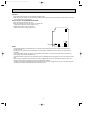
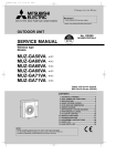
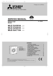
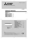
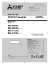
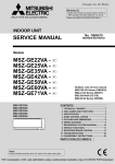
SPLIT-TYPE, HEAT PUMP AIR CONDITIONERS
• PARTS LIST and RoHS PARTS LIST have been
changed.
Please void OB388 REVISED EDITION-B
INDOOR UNIT
SERVICE MANUAL
No. OB388
REVISED EDITION-C
Wireless type
Models
MSZ-GA50VA MSZ-GA60VA MSZ-GA71VA -
E1
E1
E1
Outdoor unit service manual
MUZ-GA•VA Series (OB389)
MXZ-A•VA Series (OB377)
CONTENTS
1. TECHNICAL CHANGES ····································2
2. PART NAMES AND FUNCTIONS······················3
3. SPECIFICATION·················································5
4. NOISE CRITERIA CURVES ·······························6
5. OUTLINES AND DIMENSIONS ·························7
6. WIRING DIAGRAM ············································8
7. REFRIGERANT SYSTEM DIAGRAM ················9
8. SERVICE FUNCTIONS ····································10
9. TROUBLESHOOTING······································12
10. DISASSEMBLY INSTRUCTIONS·····················24
11. PARTS LIST······················································27
12. RoHS PARTS LIST···········································28
13. OPTIONAL PARTS···········································30
NOTE:
RoHS compliant products have <G> mark on the spec name plate.
For servicing of RoHS compliant products, refer to the RoHS Parts List.
OB388C.qxp
06.12.25 11:04 AM
Page 2
Revision:A
Part number of INDOOR HEAT EXCHANGER has been corrected..
Model
MSZ-GA60VA -
Revise point
E1
11-2.No.10
INDOOR HEAT EXCHANGER
Revision:B
• RoHS PARTS LIST has been added.
• 9-2. Failure mode recall function has been
changed.
Revision:C
• PARTS LIST and RoHS PARTS LIST have been changed.
1
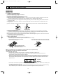
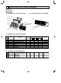
TECHNICAL CHANGES
MSZ-A18YV - E1
MSZ-A24YV - E1
MSZ-A26YV - E1
1.
2.
3.
4.
5.
6.
Part No.
Part Name
➔ MSZ-GA50VA - E1
➔ MSZ-GA60VA - E1
➔ MSZ-GA71VA - E1
Indication of capacity has been changed.(BTU base ➔kW base)
Power supply cord has been removed.
Indoor electronic control P.C. board has been changed.
Indoor fan motor has been changed. ( AC ➔ DC)
Shape of motor band and motor bed have been changed.
Symbol on terminal block has been changed (to S1/S2/S3).
2
Incorrect
Correct
E02 819 620
E02 851 620
OB388C.qxp
06.12.25 11:04 AM
2
Page 3
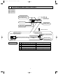
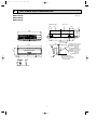
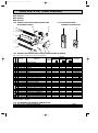
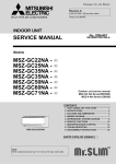
PART NAMES AND FUNCTIONS
MSZ-GA50VA
MSZ-GA60VA
MSZ-GA71VA
Air cleaning filter (option)
(Anti-allergy enzyme
filter:blue bellows type)
Grille
Air inlet
Catechin air filter
Remote control
receiving section
Vertical vanes
Horizontal vane
Remote controller
Operation section
Display section
(When the grille is opened)
Operation indicator lamp
Emergency operation switch
Remote control
receiving section
ACCESSORIES
1
2
3
4
5
6
7
Installation plate
Installation plate fixing screw 4 o 25 mm
Remote controller holder
Fixing screw for 3 o 3.5 o 1.6 mm (Black)
Battery (AAA) for remote controller
Wireless remote controller
Felt tape (Used for left or left-rear piping)
3
1
7
1
2
2
1
1
OB388C.qxp
06.12.25 11:04 AM
Page 4
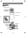
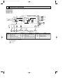
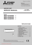
REMOTE CONTROLLER
MSZ-GA50VA
MSZ-GA60VA
MSZ-GA71VA
Signal transmitting section
Operation display section
OPERATE /STOP
(ON /OFF)button
TOO
ON/OFF WARM
TOO
COOL
TEMPERATURE buttons
Indication of remote controller
model is on back.
Open the front lid.
WIDE VANE button
(Vertical vane button)
FAN SPEED CONTROL button
OPERATION SELECT button
OFF-TIMER button
ECONO COOL button
ON-TIMER button
LONG
TIME SET buttons
FORWARD button
BACKWARD button
LONG button
CLOCK SET button
VANE CONTROL button
(Horizontal vane button)
RESET button
4
06.12.25 11:04 AM
3
Page 5
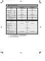
SPECIFICATION
Indoor model
Function
Power supply
Special
remarks
Electrical
data
Capacity Air flow(High/Med./Low)
Power outlet
Running current ✽1
Power input ✽1
Power factor ✽1
Fan motor current ✽1
Fan motor Model
Dimensions WOHOD
Weight
Air direction
Sound level(High/Med./Low)
Fan speed(High/Med./Low)
Fan speed regulator
Remote controller model
K /h
A
A
W
%
A
mm
kg
dB
rpm
MSZ-GA50VA
Cooling
Heating
Single phase
230V, 50Hz
852/690/498
20
0.45
50
48
0.45
RC0J56-AA
1,100O325O258
16
5
48/38/31
1,120/940/720
3
KM05C
Cooling
Electrical
data
Heating
Single phase
230V, 50Hz
Power supply
Capacity Air flow(High/Med./Low)
Power outlet
Running current ✽1
Power input ✽1
Power factor ✽1
Fan motor current ✽1
Fan motor Model
Dimensions WOHOD
Weight
Air direction
Sound level(High/Med./Low)
Fan speed(High/Med./Low)
Fan speed regulator
Remote controller model
MSZ-GA60VA
Heating
Single phase
230V, 50Hz
1,032/768/522
1,032/786/522
20
0.60
60
43
0.60
RC0J56-AA
1,100O325O258
16
5
54/40/32
1,310/1030/750
1,310/1050/750
3
KM05C
Cooling
MSZ-GA71VA
Indoor model
Function
Special
remarks
OB388C.qxp
K /h
A
A
W
%
A
1,032/798/564
mm
kg
dB
rpm
NOTE: Test conditions are based on ISO 5151.
Cooling : Indoor Dry-bulb temperature 27°C
Outdoor Dry-bulb temperature 35°C
Heating : Indoor Dry-bulb temperature 20°C
Outdoor Dry-bulb temperature 7°C
Indoor-Outdoor piping length 5m
✽1 Measured under rated operating frequency.
1,032/816/564
20
0.60
60
43
0.60
RC0J56-AA
1,100O325O258
16
5
54/40/33
1,310/1,060/800
1,310/1,080/800
3
KM05C
Wet-bulb
Wet-bulb
Wet-bulb
Wet-bulb
5
temperature 19°C
temperature(24°C)
temperature 15.5°C
temperature 6°C
OB388C.qxp
06.12.25 11:04 AM
Page 6
Specifications and rating conditions of main electric parts
(F11)
Fuse
MP20/MP20
(NR11)
Varistor
ERZV14D471
(TB)
Terminal block
4
T3.15AL 250V
(MV1/ MV2)
Vane motor
4P
NOISE CRITERIA CURVES
MSZ-GA50VA
FAN SPEED SPL(dB(A))
High
LINE
MSZ-GA60VA
MSZ-GA71VA
FAN SPEED SPL(dB(A))
48
High
80
70
NC-70
60
NC-60
50
NC-50
40
NC-40
30
NC-30
20
10
APPROXIMATE
THRESHOLD OF
HEARING FOR
CONTINUOUS
NOISE
63
125
NC-20
250
500
1000
2000
4000
54
Test conditions
Cooling : Dry-bulb temperature 27: Wet-bulb temperature 19:
Heating : Dry-bulb temperature 20: Wet-bulb temperature 15.5:
90
OCTAVE BAND SOUND PRESSURE LEVEL, dB re 0.0002 MICRO BAR
OCTAVE BAND SOUND PRESSURE LEVEL, dB re 0.0002 MICRO BAR
Test conditions
Cooling : Dry-bulb temperature 27: Wet-bulb temperature 19:
Heating : Dry-bulb temperature 20: Wet-bulb temperature 15.5:
90
LINE
80
70
NC-70
60
NC-60
50
NC-50
40
NC-40
30
NC-30
20
10
8000
BAND CENTER FREQUENCIES, Hz
APPROXIMATE
THRESHOLD OF
HEARING FOR
CONTINUOUS
NOISE
63
125
NC-20
250
500
1000
2000
4000
8000
BAND CENTER FREQUENCIES, Hz
INDOORUNIT
WALL
1m
0.8m
MICROPHONE
6
06.12.25 11:04 AM
5
Page 7
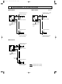
OUTLINES AND DIMENSIONS
MSZ-GA50VA
MSZ-GA60VA
MSZ-GA71VA
Unit: mm
Installation plate
Indoor unit
7.5
173
98
414.5
414.5
173
47
2.5
47
255.5
1068
315
98
Wall hole [75
258
1100
Air in
5
Installation plate
{
Liquid line [ 6.35- 0.5m
Gas line [ 12-0.43m
Insulation [ 50 O.D
[ 32 I.D
for MSZ-GA50/60VA
Liquid line [ 9.52- 0.5m
Gas line [ 12-0.43m
Insulation [ 50 O.D
[ 32 I.D
for MSZ-GA71VA
{
325
791
56
253
Air out
58
Drain hose [16
(Connected part O.D)
Insulation [28
19
159
OB388C.qxp
Wireless remote controller
7
OB388C.qxp
06.12.25 11:04 AM
6
Page 8
WIRING DIAGRAM
MSZ-GA50VA
MSZ-GA60VA
MSZ-GA71VA
TB
230V~
S1
S2
TO OUTDOOR
UNIT
CONNECTING
S3
12-24V
TAB3 F11
BLK
INDOOR ELECTRONIC
CONTROL P.C. BOARD
DB111
BLU
RED
2
1
4
CN
111
NR11
1
2
3
4
5
6
GRN
LD104
5
CN
151
5
CN
101
5
MV2 MV2 MV1
LD
105(T)
3
POWER MONITOR
P.C.BOARD
RT12
1
T111
CN201
CN
152
RT13
CN 3
112 2
RT11
RED
BLK 5
WHT
YLW
BLU
MF
CN211
2
3
RECEIVER
P.C.BOARD
REMOTE
CONTROLLER
SW P.C.
BOARD
SYMBOL
NAME
DB111
DIODE STACK
MV2
VANE MOTOR (VERTICAL)
RT13
INDOOR COIL THERMISTOR (SUB)
F11
FUSE (3.15A)
NR11
VARISTOR
T111
TRANSFORMER
MF
INDOOR FAN MOTOR
RT11
ROOM TEMPERATURE THERMISTOR
VANE MOTOR (HORIZONTAL)
RT12
INDOOR COIL THERMISTOR (MAIN)
SYMBOL
MV1
NAME
SYMBOL
NAME
NOTES: 1.About the outdoor side electric wiring refer to the outdoor unit electric wiring diagram for servicing.
2.Use copper conductors only. (For field wiring)
3.Symbols below indicate.
: Terminal block
: Connector
8
TB
TERMINAL BLOCK
OB388C.qxp
06.12.25 11:04 AM
7
Page 9
REFRIGERANT SYSTEM DIAGRAM
MSZ-GA50VA
MSZ-GA60VA
Unit:mm
Refrigerant pipe [15.88
(with heat insulator)
Refrigerant pipe [12.7
(with heat insulator)
Indoor coil
thermistor
RT12(main)
Distributor
Indoor
heat
exchanger
Indoor
heat
exchanger
Indoor coil
thermistor
RT12(main)
Distributor
Flared connection
Indoor coil
thermistor
RT13(sub)
Indoor coil
thermistor
RT13(sub)
Room temperature
thermistor
RT11
Room temperature
thermistor
RT11
Flared connection
Flared connection
Refrigerant pipe[6.35
(with heat insulator)
Refrigerant pipe [6.35
(with heat insulator)
MSZ-GA71VA
Refrigerant pipe [15.88
(with heat insulator)
Indoor
heat
exchanger
Indoor coil
thermistor
RT12(main)
Flared connection
Flared connection
Indoor coil
thermistor
RT13(sub)
Room temperature
thermistor
RT11
Strainer
#50
Flared connection
Refrigerant pipe [9.52
(with heat insulator)
Refrigerant flow in cooling
Refrigerant flow in heating
9
OB388C.qxp
06.12.25 11:04 AM
8
Page 10
SERVICE FUNCTIONS
MSZ-GA50VA
MSZ-GA60VA
MSZ-GA71VA
8-1. TIMER SHORT MODE
For service, set time can be shortened by short circuit of JPG and JPS on the electronic control P.C. board.
The time will be shortened as follows.
Set time : 1 minute ➔ 1-second
Set time : 3 minute ➔ 3-second (It takes 3 minutes for the compressor to start operation. However, the starting time is
shortened by short circuit of JPG and JPS.)
8-2. P.C. BOARD MODIFICATION FOR INDIVIDUAL OPERATION
A maximum of 4 indoor units with wireless remote controllers can be used in a room.
In this case, to operate each indoor unit individually by each remote controller, P.C. boards of remote controller must be
modified according to the number of the indoor unit.
How to modify the remote controller P.C. board
Remove batteries before modification.
The board has a print as shown below :
NOTE : For modification, take out
the batteries and press the
OPERATE/STOP(ON/OFF)
button twice or 3 times at first.
After finish modification,
put back the batteries then
press the RESET button.
J1
J2
The P.C. board has the print “J1” and “J2”. Solder “J1” and “J2” according to the number of indoor unit as shown in Table 1.
After modification, press the RESET button.
Table 1
1 unit operation
2 units operation
3 units operation
4 units operation
No. 1 unit
No modification
Same as at left
Same as at left
Same as at left
No. 2 unit
–
Solder J1
Same as at left
Same as at left
No. 3 unit
–
–
Solder J2
Same as at left
No. 4 unit
–
–
–
Solder both J1 and J2
How to set the remote controller exclusively for particular indoor unit
After you turn the breaker ON, the first remote controller that sends the signal to the indoor unit will be regarded as the
remote controller for the indoor unit.
The indoor unit will only accepts the signal from the remote controller that has been assigned to the indoor unit once they are
set. The setting will be cancelled if the breaker has turned off, or the power supply has shut down.
Please conduct the above setting once again after the power has restored.
8-3. AUTO RESTART FUNCTION
When the indoor unit is controlled with the remote controller, the operation mode, set temperature, and the fan speed are
memorized by the indoor electronic control P.C. board. The “AUTO RESTART FUNCTION” sets to work the moment power
has restored after power failure. Then, the unit will restart automatically.
10
06.12.25 11:04 AM
Page 11
Operation
1If the main power has been cut, the operation settings remain.
2After the power is restored, the unit restarts automatically according to the memory.(However, it takes at least 3 minutes
for the compressor to start running.)
How to release “AUTO RESTART FUNCTION”
1Turn OFF the main power for the unit.
2Pull out the electronic control P.C. board, the receiver P.C.
board and the display P.C.board. (Refer to 10.2.)
3Solder jumper wire to JR07 on the indoor
JR07
BZ
CN151
CN152
CN112
CN211
electronic control P.C. board. (Refer to 9-7.)
CN101
OB388C.qxp
NOTE
•The operation settings are memorized when 10 seconds have passed after the indoor unit was operated with the
remote controller.
•If main power is turned OFF or a power failure occurs while AUTO START/STOP timer is active ,the timer setting is
cancelled.
•If the unit has been off with the remote controller before power failure, the auto restart function does not work as the
power button of the remote controller is off.
•To prevent breaker off due to the rush of starting current, systematize other home appliances not to turn ON at the same
time.
•When some air conditioners are connected to the same supply system, if they are operated before power failure, the
starting current of all the compressors may flow simultaneously at restart.
Therefore, the special counter-measures are required to prevent the main voltage-drop or the rush of the starting current
by adding to the system that allows the units to start one by one.
11
OB388C.qxp
9
06.12.25 11:04 AM
Page 12
TROUBLESHOOTING
MSZ-GA50VA
MSZ-GA60VA
MSZ-GA71VA
9-1. Cautions on troubleshooting
1. Before troubleshooting, check the following:
(1) Check the power supply voltage.
(2) Check the indoor/outdoor connecting wire for mis-wiring.
2. Take care of the following during servicing
(1) Before servicing the air conditioner, be sure to turn OFF the main unit first with the remote controller, and then after
confirming the horizontal vane is closed, turn OFF the breaker and / or disconnect the power plug.
(2) Be sure to turn OFF the power supply before removing the front panel, the cabinet, the top panel, and the electronic
control P.C. board.
(3) When removing the electronic control P.C. board, hold the edge of the board with care NOT to apply stress on the
components.
(4) When connecting or disconnecting the connectors, hold the housing of the connector. DO NOT pull the lead wires.
Housing point
Lead wiring
3. Troubleshooting procedure
(1) First, check if OPERATION INDICATOR lamp on the indoor unit is flashing on and off to indicate an abnormality.
To make sure, check how many times the abnormality indication is flashing on and off before starting service work.
(2) Before servicing, check that the connector and terminal are connected properly.
(3) If the electronic control P.C. board is supposed to be defective, check the copper foil pattern for disconnection and the
components for bursting and discolouration.
(4) When troubleshooting, refer to 9-2., 9-3. and 9-4.
4. How to replace batteries
Weak batteries may cause the remote controller malfunction.
In this case, replace the batteries to operate the remote controller normally.
1 Remove the front lid and insert batteries.
2 Press the RESET button with tip end of ball point
Then reattach the front lid.
pen or the like, and then use the remote controller.
Insert the negative pole of the
batteries first. Check if the polarity
of the batteries is correct.
RESET button
NOTE : If the RESET button is not pressed, the remote controller may not operate correctly.
INFORMATION FOR MULTI SYSTEM AIR CONDITIONER
OUTDOOR UNIT : MXZ series
Multi system air conditioner can connect two or more indoor units with one outdoor unit.
•Unit won’t operate in case the total capacity of indoor units exceeds the capacity of outdoor units. Do not
connect indoor units beyond the outdoor unit capacity.
•When you try to operate two or more indoor units with one outdoor unit simultaneously, one for the cooling and
the other for heating, the operation mode of the indoor unit that operates earlier is selected. The other indoor units
cannot operate, indicating as shown in the figure below. In this case, please set all the indoor units to the same
operation mode.
Lighted
Blinking
•When indoor units starts the operation while the defrosting of outdoor unit is being done, it takes a few minutes (max.
10 minutes) to blow out the warm air.
•In the heating operation, though indoor unit that does not operate may get warm or the sound of refrigerant flowing
may be heard, they are not malfunction. The reason is that the refrigerant continuously flows into it.
12
OB388C.qxp
06.12.25 11:04 AM
Page 13
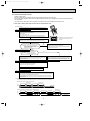
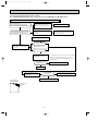
9-2. Failure mode recall function
Outline of the function
This air conditioner can memorize the abnormal condition which has occurred once.
Even though LED indication listed on the troubleshooting check table (9-4.) disappears, the memorized failure details
can be recalled.
This mode is very useful when the unit needs to be repaired for the abnormality which doesn't recur.
1. Flow chart of failure mode recall function for the indoor/outdoor unit
Operational procedure
The cause of abnormality cannot be found because the abnormality doesn't recur.
Setting up the failure mode recall function
Turn ON the power supply.
<Preparation of the remote controller>
1 While pressing both OPERATION SELECT
button and TOO COOL button on the remote controller at the same time, press
RESET button.
2 First, release RESET button.
And release the other two buttons after all LCD except the set temperature in
operation display section of the remote controller is displayed after 3 seconds.
W1. Regardless of normal or abnormal condition,
a short beep is emitted once the signal
is received.
Press OPERATE/STOP(ON/OFF) button of the remote controller (the set temperature
is displayed) with the remote controller headed towards the indoor unit. W1
Does the left lamp of OPERATION INDICATOR lamp
on the indoor unit blink at the interval of 0.5 seconds?
Blinks: Either indoor or outdoor unit is abnormal.
Beep is emitted at the same timing
as the blinking of the left lamp of OPERATION
INDICATOR lamp. W2
Yes
Judgment of indoor/outdoor abnormality
(Blinks)
No
(OFF)
Before blinking, does the left lamp of
OPERATION INDICATOR lamp stay ON for
3 seconds?
Stays ON for 3 seconds (without beep):
The outdoor unit is abnormal.
Indoor unit is normal.
But the outdoor unit might be abnormal because there are some
abnormalities that can't be recalled with this way.
Confirm if outdoor unit is abnormal according to the detailed outdoor
unit failure mode recall function.
Yes
No
The indoor unit is abnormal.
Check the blinking pattern, and confirm the abnormal point with the indoor unit
failure mode table(9-2.2.).
Make sure to check at least two consecutive blinking cycles. W2
The outdoor unit is abnormal.
Check the blinking pattern, and confirm the abnormal point with the
outdoor unit failure mode table (Refer to outdoor unit service manual.)
Make sure to check at least two consecutive blinking cycles. W3
Releasing the failure mode recall function
Release the failure mode recall function by the following procedures.
Turn OFF the power supply and turn it ON again.
Press RESET button of the remote controller.
Repair the defective parts.
Deleting the memorized abnormal condition
1After repairing the unit, recall the failure mode again according to
"Setting up the failure mode recall function" mentioned above.
2Press OPERATE/STOP(ON/OFF) button of the remote controller (the set temperature is displayed)
with the remote controller headed towards the indoor unit.
3Press EMERGENCY OPERATION switch so that the memorized abnormal condition is deleted.
4Release the failure mode recall function according to "Releasing the failure mode recall function"
mentioned above.
Note1.Make sure to release the failure mode recall function once it's set up, otherwise the unit cannot operate properly.
2.If the abnormal condition is not deleted from the memory, the last abnormal condition is kept memorized.
W2. Blinking pattern when the indoor unit is abnormal:
Blinking at 0.52.5-second OFF second interval
Blinking at 0.52.5-second OFF second interval
ON
OFF
Beeps
Repeated cycle
Beeps
Repeated cycle
Beeps
Repeated cycle
W3.Blinking pattern when the outdoor unit is abnormal:
Blinking at 0.52.5-second OFF
3-second ON
second interval
2.5-second OFF
3-second ON
Blinking at 0.5second interval
ON
OFF
No beep
Repeated cycle
Beeps
No beep
Repeated cycle
13
Beeps
Repeated cycle
OB388C.qxp
06.12.25 11:04 AM
Page 14
2. Indoor unit failure mode table
Left lamp of
OPERATION
INDICATOR lamp
Abnormal point
(Failure mode)
Condition
Correspondence
Not lighted
Normal
–
–
1-time flash
every 0.5-second
Room temperature
thermistor
When the room temperature thermistor
short or open circuit is detected every 8
seconds during operation.
Refer to the characteristics of the room
temperature thermistor (9-7.).
2-time flash
2.5-second OFF
Indoor coil thermistor
When the indoor coil thermistor short or
open circuit is detected every 8 seconds
during operation.
Refer to the characteristics of the main
indoor coil thermistor, the sub indoor coil
thermistor (9-7.).
3-time flash
2.5-second OFF
Serial signal
When the serial signal from the outdoor unit is Refer to 9-6.D "How to check mis-wiring
not received for a maximum of 6 minutes.
and serial signal error".
11-time flash
2.5-second OFF
Indoor fan motor
When the rotational frequency feedback
signal is not emitted during the 12-seconds
indoor fan operation.
Refer to 9-6.A "Check of indoor fan
motor".
12-time flash
2.5-second OFF
Indoor control system
When it cannot properly read data in the
nonvolatile memory of the indoor electronic
control P.C. board.
Replace the indoor electronic control
P.C. board.
NOTE : Blinking patterns of this mode differ from the ones of Troubleshooting check table (9-4.).
14
OB388C.qxp
06.12.25 11:04 AM
Page 15
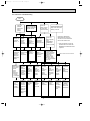
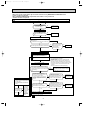
9-3. Instruction of troubleshooting
Start
Indoor unit
operates.
Outdoor unit
doesn't
operate.
Outdoor unit
operates only
in Test Run
operation. w
Check room
temperature
thermistor.
Refer to 9-7.
"Test point
diagram and
voltage".
Indoor unit operates.
Outdoor unit doesn't
operate normally.
Indoor unit
doesn't receive
the signal from
remote controller.
OPERATION INDICATOR
lamp on the indoor unit is
flashing on and off.
If blinking of OPERATION
INDICATOR lamp cannot be
checked, it can be checked with
failure mode recall function.
Outdoor unit
doesn't
operate
even in
Test Run
operation. w
Unit doesn't
operate
normal
operation in
COOL or
HEAT mode.
Indoor unit
operates, when
EMERGENCY
OPERATION
switch is pressed.
Indoor unit
doesn't operate,
when
EMERGENCY
OPERATION
switch is pressed.
Refer to
"How to check
inverter/
compressor".
Refer to
"Check of
R.V. coil".
Refer to 9-6.B
"Check of
remote controller
and receiver
P.C. board".
1. Check indoor / outdoor
connecting wire.
(Check if the power
is supplied to the
indoor unit.)
2. Refer to 9-6.C
"Check of indoor
electronic control
P.C. board and indoor
fan motor".
Left lamp
Flash on and off
at 0.5-second
intervals
Cause:
Indoor/
Outdoor unit
• Mis-wiring
or trouble
of serial signal
Left lamp
2-time flash
Cause:
Indoor unit
• Trouble of
room temperature/
indoor coil
thermistor
Refer to 9-6.
D "How to
check
mis-wiring
and serial
signal error".
Check room
temperature
thermistor
and indoor
coil thermistor.
Refer to 9-7.
"Test point
diagram and
voltage".
Left lamp
3-time flash
Cause:
Indoor unit
• Trouble of
indoor fan
motor
Refer to 9-6.
A "Check of
indoor fan
motor".
Left lamp
4-time flash
Cause:
Indoor unit
• Trouble of
indoor unit
control
system
Replace the
indoor
electronic
control
P.C. board.
w "Test Run operation" means the
operation within 30 minutes after
EMERGENCY OPERATION switch
is pressed.
Refer to outdoor unit service manual.
Left lamp
5-time flash
Cause:
Outdoor unit
• Outdoor
power
system
abnormality
Left lamp
6-time flash
Cause:
Outdoor unit
• Trouble of
thermistor
in outdoor
unit
Left lamp
7-time flash
Cause:
Outdoor unit
• Trouble of
outdoor
control
system
Left lamp
14-time flash
Cause:
Outdoor unit
• Other
abnormality
Refer to
"How to check
inverter/
compressor".
Refer to
"Check of
outdoor
thermistors".
Replace the
inverter P.C.
board or
the outdoor
electronic
control P.C.
board.
Check
"Flow chart of
the detailed
outdoor unit
failure mode
recall function."
15
OB388C.qxp
06.12.25 11:04 AM
Page 16
9-4. Troubleshooting check table
Before taking measures, make sure that the symptom reappears for accurate troubleshooting.
When the indoor unit has started operation and the following detection method has detected an abnormality (the first
detection after the power ON), the indoor electronic control P.C. board turns OFF the indoor fan motor with
OPERATION INDICATOR lamp flashing.
Lighted
Blinking
· Flashing of OPERATION INDICATOR lamp (left-hand side lamp)
indicates abnormalities.
Not Lighted
No.
Abnormal
point
1
Mis-Wiring
or serial
signal
Operation indicator lamp
Left lamp flashes.
0.5-second ON
Condition
Symptom
Indoor unit
and outdoor
unit do not
operate.
When serial signal from outdoor unit is not
received for a maximum of 6 minutes.
Correspondence
• Refer to 9-6.D "How to check
mis-wiring and serial signal
error".
0.5-second OFF
Indoor coil
thermistor
2
3
Room
temperature
thermistor
Indoor fan
motor
Left lamp flashes.
2-time flash
Indoor unit
and outdoor
unit do not
operate.
When the indoor coil or room temperature
thermistor is short or open circuit.
• Refer to 9-7.the
characteristics of indoor coil
thermistor, and the room
temperature thermistor.
When rotational frequency feedback signal is
not emit during indoor fan operation.
• Refer to 9-6.A "Check of
indoor fan motor".
Indoor unit
and outdoor
unit do not
operate.
When it cannot properly read data in the
nonvolatile memory of indoor electronic
control P.C. board.
• Replace the indoor electronic
control P.C. board.
Indoor unit
and outdoor
unit do not
operate.
When it consecutively occurs 3 times that the
compressor stops for overcurrent protection or
start-up failure protection witth in 1 minute
after start-up.
• Refer to "How to check of
inverter/compressor".
Refer to outdoor unit service
manual .
• Check the stop valve.
2.5-second OFF
Left lamp flashes.
3-time flash
Indoor unit
and outdoor
unit do not
operate.
2.5-second OFF
4
Indoor
control
system
Left lamp flashes.
4-time flash
2.5-second OFF
5
Outdoor
power
system
Left lamp flashes.
5-time flash
2.5-second OFF
Left lamp flashes.
6-time flash
6
Indoor unit
and outdoor
unit do not
operate.
Outdoor
thermistors
Outdoor thermistors short or open circuit
during compressor operation.
• Refer to "Check of outdoor
thermistor".
Refer to outdoor unit service
manual.
2.5-second OFF
7
Outdoor
control
system
Left lamp flashes.
7-time flash
2.5-second OFF
8 Other
abnormality
Left lamp flashes.
14-time flash
Indoor unit
and outdoor
unit do not
operate.
When it cannot properly read data in the
nonvolatile memory of the inverter P.C. board
or the outdoor electronic control P.C. board.
• Replace the inverter P.C.
board or the outdoor
electronic control P.C. board.
Refer to outdoor unit service
manual.
Indoor unit
and outdoor
unit do not
operate.
An abnormality other than above mentioned is
detected.
• Confirm the abnormality in
detail using the failure mode
recall function for outdoor unit.
2.5-second OFF
16
OB388C.qxp
06.12.25 11:04 AM
Page 17
Lighted
· Flashing of OPERATION INDICATOR lamp (right-hand side lamp) indicates
abnormality.
· OPERATION INDICATOR lamp (left-hand side lamp) is lighted.
Blinking
Not Lighted
No.
Abnormal
point
1
MXZ type
Operation
mode
setting
Operation indicator lamp
Right lamp flash
2.5-second OFF
Symptom
Condition
Outdoor unit
operates but
indoor unit
does not
operate.
When the operation mode of each indoor unit
is differently set to COOL(includes DRY) and
HEAT at the same time, the operation mode of
indoor unit that has operated at first has the
priority.
Correspondence
• Unify the operation mode.
Refer to outdoor unit
service manual.
9-5. Trouble criterion of main parts
MSZ-GA50VA MSZ-GA60VA MSZ-GA71VA
Part name
Room temperature
thermistor(RT11)
Indoor coil thermistor
(RT12(MAIN), RT13(SUB))
Indoor fan motor(MF)
Horizontal vane
motor(MV1)
Vertical vane
motor(MV2)
Check method and criterion
Figure
Measure the resistance with a tester.
Refer to 9-7. "Test point diagram and voltage", "Indoor electronic control
P.C. board", the chart of thermistor.
Check 9-6. A.
Measure the resistance between the terminals with a tester.
(Part temperature 10°C ~ 30°C)
Color of the lead wire
BRN-other one
Normal
282 " ~ 306 "
17
RED
ROTOR
YLW
BRN
ORN
GRN
OB388C.qxp
06.12.25 11:04 AM
Page 18
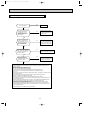
9-6. Troubleshooting flow
When OPERATION INDICATOR lamp flashes 3-time.
Indoor fan does not operate.
A Check of indoor fan motor
The indoor fan motor error has occurred, and the indoor fan doesn't operate.
Turn OFF the power supply.
Pay careful attention to the high voltage on
the fan motor connector CN211.
Is there any foreign matter that
interferes the rotation of the
line flow fan?
Turn ON the power supply, wait 5 seconds or more, and then press
EMERGENCY OPERATION switch.
Measure the supply voltage as follows within 12 seconds
after EMERGENCY OPERATION switch is pressed.
If more than 12 seconds passes by, turn OFF the power supply and
turn ON it again, then measure the voltage. w
1.Measure the voltage between CN211 1(+) and 3(-).
2.Measure the voltage between CN211 5(+) and 3(-).
No
Yes
w If more than 12 seconds passes after EMERGENCY OPERATION switch
is pressed, the voltage mentioned above 2 goes 0V DC although the
indoor electric control P.C. board is normal.
Remove the foreign matter and
adjust the line flow fan.
Is there 325V DC between
CN211 1 (+) and 3 (-), and does
the voltage between CN211 5(+)
and 3(-) rise to the range of 3 to 6V
DC within 12 seconds after
EMERGENCY OPERATION switch
is pressed?
CN211
Yes
Replace the indoor fan motor.
Indoor electronic
control P.C. board
No
Replace the indoor electronic control P.C. board.
The indoor fan motor error has occurred, and the indoor fan repeats "12-second ON and 30-second OFF" 3 times, and then stops.
Measure the voltage between CN211
6(+) and 3(-) while the fan
motor is rotating.
Is it unchanged holding
0V DC or 15V DC?
No
(Changed)
Yes
(Unchanged)
Replace the indoor fan motor.
18
Replace the indoor electronic control P.C. board.
OB388C.qxp
06.12.25 11:04 AM
Page 19
Indoor unit operates by pressing EMERGENCY OPERATION switch, but does not operate with the remote controller.
B Check of remote controller and receiver P.C. board
wCheck if the remote controller is exclusive for this air conditioner.
Press OPERATE/STOP(ON/OFF) button on the remote controller.
Is LCD display on the the remote
controller visible?
No
Replace the batteries. (Refer to 9-1.4.)
(not clear)
Yes
Remove the batteries, then set them back
and press RESET button. (Refer to 9-1.4.)
Check if the unit operates with the remote
controller.
Does the unit operate with the
remote controller?
No
Turn ON a radio to AM and press
OPERATE/STOP(ON/OFF) button on
the remote controller.
Yes
OK
No
Is noise heard from radio?
Replace the remote controller.
Yes
Are there any fluorescent lights of
inverter or rapid-start type within
the range of 1m?
Yes
● Reinstall the unit away from lights.
● Attach a filter on receiving part.
Measure the voltage between receiver P.C. board connector CN301 No.2(+) and No.3(-) when the remote
controller button is pressed.
Yes
Is the voltage approx. 4V DC?
No
(5V or 0V DC)
Replace the receiver P.C. board.
19
Replace the indoor electronic control P.C.
board.
OB388C.qxp
06.12.25 11:04 AM
Page 20
The unit does not operate with the remote controller.
Also, OPERATION INDICATOR lamp does not light up by pressing EMERGENCY OPERATION switch.
C Check of indoor electronic control P.C. board and indoor fan motor
Turn OFF the power supply.
Remove indoor fan motor connector CN211 and
vane motor connector CN151 from the indoor electronic
control P.C. board and turn ON the power supply.
Measure the resistance between CN211 3
and 4 of the indoor fan motor connector.
Short/open circuit:
Replace the indoor fan motor.
Yes
Does the unit operate with the remote controller?
Does OPERATION INDICATOR lamp light up by
pressing EMERGENCY OPERATION switch?
Measure the resistance of the horizontal vane
motor coil.
Refer to 9-5.
Short/open circuit:
Replace the horizontal vane motor and the indoor
electronic control P.C. board.
No
Replace the varistor(NR11) and fuse(F11).
Yes
No
Are the varistor(NR11) burnt
and the fuse(F11) blown?
Turn OFF the power supply.
Check both “parts side” and “pattern
side” of the indoor electronic control P.C.
board visually.
Be sure to check both the fuse
and the varistor in any case.
No
Is the fuse(F11) blown only?
Yes
Measure the resistance between
1(+) and 3(-) of the indoor fan
motor connector.
w1,w2
Is the resistance 1M'
or more?
w1. The fan motor connector's 1 lead wire is red, whereas 3 is black.
w2. Connect "+" of the tester to fan motor connector's 1 lead
wire, and "-" to 3 lead wire, otherwise the resistance cannot be
measured properly.
No
Replace the fuse (F11) and the indoor fan motor.
Yes
Replace the fuse (F11).
Measure the resistance of cement
resistor R111 on the indoor electronic
control P.C. board.
Is the resistance
approx. 4'?
No
Yes
Replace the indoor electronic control P.C. board.
Indoor electronic
control P.C.Board
Varistor(NR11)
Fuse(F11)
CN211
20
Replace the indoor electronic control P.C. board
and the indoor fan motor.
OB388C.qxp
06.12.25 11:04 AM
Page 21
• When unit cannot operate neither by the remote controller nor by EMERGENCY OPERATION switch.
Indoor unit does not operate.
• When OPERATION INDICATOR lamp flashes ON and OFF in every 0.5-second.
Outdoor unit does not operate.
D How to check mis-wiring and serial signal error (when outdoor unit does not work)
Turn OFF the power supply.
Is there rated voltage in
the power supply?
No
Check the power
supply.
Yes
Turn ON the power supply.
Is there rated voltage between
outdoor terminal block S1 and
S2?
No
Check the wiring.
Yes
Press EMERGENCY OPERATION switch once.
Does the left lamp of OPERATION INDICATOR
lamp light up?
<Confirmation of the power to the indoor unit>
No
Yes
Is serial signal error indicated 6 minutes later?
No
Yes
Is there any mis-wiring,
poor contact, or wire
disconnection of the
indoor/outdoor
connecting wire?
Yes
Correct them.
No
A
Turn OFF the power supply.
Check once more if the indoor/outdoor
B connecting wire is not mis-wiring.
Short-circuit outdoor terminal block S2 and
S3.
W1
Turn ON the power supply.
W1. Mis-wiring may damage indoor electronic control
P.C. board during the operation.
Be sure to confirm the wiring is correct before the
operation starts.
W3.Be sure to check this within 3 minutes after turning
ON. After 3 minutes, LED blinks 6 times. Even when
the inverter P.C.board or the outdoor electronic control
P.C.board is normal, LED also blinks 6 times after
3 minutes.
(Except for outdoor unit of multi system type)
Does the LED on the inverter P.C. board
or the outdoor electronic control P.C.board
Replace the inverter P.C. board or
No
repeat "3.6-second-OFF and 0.8-second-ON
the outdoor electronic control P.C.board.
(Lighted or W2
quick blinking"?
not lighted)
W3
W2 Be careful to the residual
voltage of smoothing capacitor.
Yes
A
· Turn OFF inverter-controlled lighting
equipment.
· Turn OFF the power supply and then
turn ON again.
· Press EMERGENCY OPERATION
switch.
Is serial signal
error indicated
6 minutes later?
Yes
B
· Reinstall
either the
unit or the
light each
No other away.
· Attach a filter
on remote
control
receiving
section of
the indoor
unit.
Turn OFF the power supply.
Remove the short-circuit between
outdoor terminal block S2 and S3.
Turn ON the power supply.
Is there amplitude of 10 to 20V DC
between outdoor terminal block S2
and S3? <Confirmation of serial
signal>
No
Is there any error of the
indoor/outdoor connecting wire,
such as the damage of the wire,
intermediate connection, poor
contact to the terminal block?
Yes Replace the
indoor/outdoor
connecting wire.
No
Yes
Is there rated voltage between indoor
terminal block S1 and S2?
<Confirmation of power voltage>
No
Is there any error of the
indoor/outdoor connecting wire,
such as the damage of the wire,
intermediate connection, poor
contact to the terminal block?
Yes
No
Replace the indoor electronic control P.C. board.
Be sure to release the failure-mode
recall function after checking.
Refer to outdoor unit service manual.
21
Yes Replace the
indoor/outdoor
connecting wire.
OB388C.qxp
06.12.25 11:04 AM
Page 22
E Electromagnetic noise enters into TV sets or radios
No
Is the unit earthed?
Earth the unit.
Yes
Is the distance between the
antennas and the indoor
unit within 3m, or is the
distance between the
antennas and the outdoor
unit within 3m?
Yes
Extend the distance between
the antennas and the indoor
unit, and/or the antennas and
the outdoor unit.
No
Is the distance between the
TV sets or radios and the
indoor unit within 1m, or is
the distance between the TV
sets or radios and the
outdoor unit within 3m?
Yes
Extend the distance between
the TV sets and/or radios and
the indoor unit, or the TV sets
or radios and the outdoor unit.
No
Are the antennas damaged?
Is the coaxial cable damaged?
Is there any poor contact in
the antenna wiring?
Yes
Replace or repair the antenna.
Replace or repair the coaxial cable.
No
Is the indoor/outdoor
connecting wire of the air
conditioner and the wiring of
the antennas close?
Yes
Extend the distance between
the indoor/outdoor connecting
wire of the air conditioner and
the wiring of the antennas.
No
Even if all of the above conditions is fulfilled, the electromagnetic noise may enter, depending on
the electric field strength or the installation condition (combination of specific conditions such as
antennas or wiring).
Check the followings before asking for service.
1.Devices affected by the electromagnetic noise
TV sets, radios (FM/AM broadcast, shortwave)
2.Channel, frequency, broadcast station affected by the electromagnetic noise
3.Channel, frequency, broadcast station unaffected by the electromagnetic noise
4.Layout of ;
indoor/outdoor unit of the air conditioner, indoor/outdoor wiring, grounding wire, antennas, wiring
from antennas, receiver
5.Electric field intensity of the broadcast station affected by the electromagnetic noise
6.Presence or absence of amplifier such as booster
7.Operation condition of air conditioner when the electromagnetic noise enters in.
1)Turn OFF the power supply once, and then turn ON the power supply. In this situation check for
the electromagnetic noise.
2)Within 3 minutes after turning ON the power supply, press OPERATE/STOP (ON/OFF) button
on the remote controller for power ON, and check for the electromagnetic noise.
3)After a short time (3 minutes later after turning ON), the outdoor unit starts running. During
operation, check for the electromagnetic noise.
4)Press OPERATE/STOP (ON/OFF) button on the remote controller for power OFF, when the
outdoor unit stops but the indoor/outdoor communication still runs on. In this situation check for
the electromagnetic noise.
After checking the above, consult the service representative.
22
06.12.25 11:04 AM
Page 23
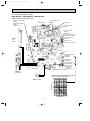
9-7. Test point diagram and voltage
MSZ-GA50VA
MSZ-GA60VA
MSZ-GA71VA
Indoor electronic control P.C. board
Varistor (NR11)
Power supply input
230V AC
Fuse(F11)
}
Release of Auto restart
function
Solder the Jumper wire
to JR07
(Refer to 8-3.)
Cement resistor
(R111)
Indoor fan motor
(CN211)
1325V DC
3(-) Fiducial terminal of
cathode side on measuring high-voltage DC
415V DC
Display
P.C.
board
5(+)3-6V DC
6(+)0V DC or 15V DC
5V DC
Indoor coil thermistor
RT12(MAIN)
RT13(SUB)
Horizontal vane
motor(CN151)
Room temperature
thermistor(RT11)
}
Timer short
mode point
JPG, JPS
(Refer to 8-1.)
Vertical vane motor (CN152)
12V DC
Receiver
P.C. board
Indoor coil thermistor [RT12 (MAIN), RT13 (SUB)]
Room temperature thermistor (RT11)
SW P.C. board
Resistance (k")
OB388C.qxp
Temperature (:)
23
OB388C.qxp
10
06.12.25 11:04 AM
Page 24
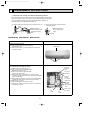
DISASSEMBLY INSTRUCTIONS
<"Terminal with locking mechanism" Detaching points>
The terminal which has the locking mechanism can be detached as shown below.
There are two types ( Refer to (1) and (2)) of the terminal with locking mechanism.
The terminal without locking mechanism can be detached by pulling it out.
Check the shape of the terminal before detaching.
(1) Slide the sleeve and check if there is a locking lever or not.
(2) The terminal with this connector has the
locking mechanism.
Sleeve
Locking lever
1Slide the sleeve.
2Pull the terminal while
pushing the locking
lever.
1Hold the sleeve, and
pull out the terminal
slowly.
Connector
MSZ-GA50VA MSZ-GA60VA MSZ-GA71VA
OPERATING PROCEDURE
PHOTOS
1. Removing the front panel
(1) Remove the screw caps of the front panel.
Remove the screws.
(2) Pull the panel down to your side slightly and unhook the
catches at the top.
Photo 1
Front panel
Screws
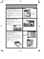
2. Removing the electronic control P.C. board, the receiver
P.C. board and the display P.C. board
(1) Remove the front panel. (Refer to 1.)
(2) Remove the screw of the electrical cover.
Remove the electrical cover.
(3) Remove the screws of the cable clamp.
Remove the cable clamp.
(4) Remove the screw of the earth wires, which is soldermounted to the electronic control P.C. board and connected
to the terminal block.
(5) While pulling the electronic control P.C. board forward little
by little, disconnect all the connectors from the board.
(6) Remove the R.L holder.
(7) Remove the electronic control P.C. board.
(8) Open the R.L holder, remove the receiver P.C. board and
the display P.C. board.
Photo 2
Screw of
the earth
wires
Fan motor
connector
Indoor
electronic
control
P.C. board
Vane motor
connector
Screw of
the electrical
cover
R.L
holder
24
Receiver
P.C.
board
Screw of the
V.A. clamp
OB388C.qxp
06.12.25 11:04 AM
Page 25
OPERATING PROCEDURE
PHOTOS
3. Removing the electrical box
(1) Remove the front panel. (Refer to 1.)
(2) Remove the electrical cover. (Refer to 2.)
(3) Disconnect the connector of the indoor coil thermistors.
(4) Disconnect the motor connector (CN211) and the vane
motor connector (CN151 and CN152) on the electronic
control P.C. board.
(5) Remove the screw of earth wire to the heat exchanger.
(6) Remove the fan motor lead wire and indoor coil thermistor
from the electrical box.
(7) Remove the lead wire of vane motor from the bottom of
electrical box.
(8) Remove the screw fixing the electrical box and remove the
electrical box.
Indoor coil
Photo 3
thermistors
4. Removing the vane motor
(1) Remove the front panel. (Refer to 1.)
(2) Remove the electrical cover. (Refer to 2.)
(3) Remove the lead wire of vane motor.(Refer to 3.)
(4) Remove the R.L. holder.
(5) Pull out the drain hose from the nozzle assembly and
remove the nozzle assembly.
(6) Remove the screws of the vane motor and disconnect the
connector.
(7) Remove the vane motor.
Photo 4
Screw of the
earth wire
Screw of the
electrical cover
Screw of the
electrical box
Vane motors
Photo 5 Screws of the
vane motor
Vane motor
5. Removing the line flow fan and the indoor fan motor
(1) Remove the front panel. (Refer to 1.)
(2) Remove the electrical box. (Refer to 3.)
(3) Pull out the drain hose from the nozzle assembly and
remove the nozzle assembly.
(4) Remove the water cut.
(5) Slide the hole cover and remove the hole cover.
(6) Remove the hexagon socket set screw from the line flow
fan.
(7) Remove the screws fixing the motor bed and remove the
fan motor. (Be careful not to drop the fan motor because it
is heavy.)
(8) Remove the screws fixing the left side of the heat
exchanger.
(9) Lift the left side of the heat exchanger.
(10) Remove the line flow fan.
Photo 8
Photo 6
Screws fixing
the left side
of the heat
exchanger
Photo 7
Water cut
Hole
cover
Screws of the motor bed
25
Screws
of the
vane
motor
OB388C.qxp
06.12.25 11:04 AM
11
Page 26
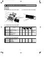
PARTS LIST (non-RoHS compliant)
MSZ-GA50VA
MSZ-GA60VA
MSZ-GA71VA
11-1. INDOOR UNIT STRUCTURAL PARTS
11-2. INDOOR UNIT HEAT EXCHANGER
1
2
10
3
4
8
5
Optional parts
(See 13.)
11
12
6
7
11-1. INDOOR UNIT STRUCTURAL PARTS
Part number that is circled is not shown in the illustration.
No.
1
2
3
4
5
6
7
8
9
Part No.
E02
E02
E02
E02
E02
E02
E02
E02
E02
527
685
888
408
685
888
534
685
918
970
234
000
142
067
010
100
975
007
Part Name
Symbol
in Wiring MSZ-GA50
Diagram VA - E1
INSTALLATION PLATE
BOX
FRONT PANEL ASSEMBLY
CATCH
SCREW CAP
GRILLE
CATECHIN AIR FILTER
CORNER BOX RIGHT
LAMP PANEL
Q'ty/unit
MSZ-GA60
VA - E1
MSZ-GA71
VA - E1
1
1
1
4
3
1
2
1
1
1
1
1
4
3
1
2
1
1
1
1
1
4
3
1
2
1
1
1
1
Remarks
Including No.4,5,6
4PCS/ SET
3PCS/ SET
11-2. INDOOR UNIT HEAT EXCHANGER
E02
E02
E02
11
E02
E02
12
E02
10
851
819
179
138
151
527
620
620
667
666
667
667
INDOOR HEAT EXCHANGER
INDOOR HEAT EXCHANGER
UNION (GAS)
UNION (GAS)
UNION (LIQUID)
UNION (LIQUID)
1
1
1
1
1
1
1
26
{12.7
{15.88
{6.35
{9.52
OB388C.qxp
06.12.25 11:04 AM
Page 27
PARTS LIST (non-RoHS compliant)
MSZ-GA50VA
MSZ-GA60VA
MSZ-GA71VA
11-4. ACCESSORY AND
REMOTE CONTROLLER
11-3. INDOOR UNIT FUNCTIONAL PARTS AND
ELECTRICAL PARTS
1
20
19
23
24
2
3
4
11
18
12
5
6
14
13
17
10
7
8
9
15
17
16
11-3. INDOOR UNIT FUNCTIONAL PARTS AND ELECTRICAL PARTS
Part numbers that are circled are not shown in the illustration.
No.
Part No.
Part Name
Symbol
in Wiring
Diagram
E02 527 302 LINE FLOW FAN
E02 408 509 BEARING MOUNT
E02 001 504 SLEEVE BEARING
E02 408 702 DRAIN HOSE
E02 A87 235 NOZZLE
E02 685 040 VANE UPPER
E02 685 041 VANE LOWER
E02 A49 382 FUSE
F11
E02 661 385 VARISTOR
NR11
E02 527 034 VANE CRANK SET
E02 918 300 INDOOR FAN MOTOR ASSEMBLY W1
MF
E02 448 303 VANE MOTOR (VERTICAL)
MV2
E02 408 303 VANE MOTOR (HORIZONTAL)
MV1
E02 918 333 MOTOR BAND
E02 918 329 DISPLAY P.C. BOARD
E02 918 468 RECEIVER P.C. BOARD
E02 918 452 ELECTRONIC CONTROL P.C. BOARD W2
17 E02 919 452 ELECTRONIC CONTROL P.C. BOARD W2
E02 920 452 ELECTRONIC CONTROL P.C. BOARD W2
18 E02 527 308 ROOM TEMPERATURE THERMISTOR
RT11
19 E02 918 375 TERMINAL BLOCK
TB
RT12, RT13
E02 918 307 INDOOR COIL THERMISTOR
20
E02 920 307 INDOOR COIL THERMISTOR
RT12, RT13
21 E02 528 034 VANE MOTOR SUPPORT SET(RIGHT)
22 E02 529 034 VANE MOTOR SUPPORT SET(LEFT)
W1 Including FAN MOTOR RUBBER MOUNT
W2 Including SW P.C. BOARD
1
2
3
4
5
6
7
8
9
10
11
12
13
14
15
16
Q'ty/unit
MSZ-GA50
VA - E1
MSZ-GA60
VA - E1
MSZ-GA71
VA - E1
1
1
1
1
1
1
1
1
1
1
1
2
1
1
1
1
1
1
1
1
1
1
1
1
1
1
1
1
2
1
1
1
1
1
1
1
1
1
1
1
1
1
1
1
2
1
1
1
1
1
1
1
1
1
1
1
1
1
1
1
1
1
1
1
1
1
1
1
1
1
1
1
Remarks
3.15A
RC0J56 RIGHT & LEFT
UP & DOWN
AUTO RESTART
AUTO RESTART
AUTO RESTART
11-4. ACCESSORY AND REMOTE CONTROLLER
23 E02 918 426
24 E02 527 083
REMOTE CONTROLLER
REMOTE CONTROLLER HOLDER
27
KM05C
OB388C.qxp
06.12.25 11:04 AM
12
Page 28
RoHS PARTS LIST (RoHS compliant)
MSZ-GA50VA
MSZ-GA60VA
MSZ-GA71VA
12-1. INDOOR UNIT STRUCTURAL PARTS
12-2. INDOOR UNIT HEAT EXCHANGER
1
2
10
3
4
8
5
Optional parts
(See 13.)
11
12
6
7
12-1. INDOOR UNIT STRUCTURAL PARTS
No.
RoHS
Part number that is circled is not shown in the illustration.
1
2
3
4
5
6
7
8
9
G
G
G
G
G
G
G
G
G
Part Name
Part No.
E12
E12
E12
E12
E12
E12
E12
E12
E12
527
685
888
408
685
888
534
685
918
970
234
000
142
067
010
100
975
007
Symbol
in Wiring MSZ-GA50
Diagram VA - E1
1
1
1
4
3
1
2
1
1
INSTALLATION PLATE
BOX
FRONT PANEL ASSEMBLY
CATCH
SCREW CAP
GRILLE
CATECHIN AIR FILTER
CORNER BOX RIGHT
LAMP PANEL
Q'ty/unit
MSZ-GA60
VA - E1
MSZ-GA71
VA - E1
1
1
1
4
3
1
2
1
1
1
1
1
4
3
1
2
1
1
Remarks
Including No.4,5,6
4PCS/ SET
3PCS/ SET
1PC/ SET
12-2. INDOOR UNIT HEAT EXCHANGER
G
G
G
11
G
G
12
G
10
E12
E12
E12
E12
E12
E12
851
819
179
138
151
527
620
620
667
666
667
667
INDOOR HEAT EXCHANGER
INDOOR HEAT EXCHANGER
UNION (GAS)
UNION (GAS)
UNION (LIQUID)
UNION (LIQUID)
1
1
1
1
1
1
1
1
1
28
{12.7
{15.88
{6.35
{9.52
06.12.25 11:04 AM
Page 29
RoHS PARTS LIST (RoHS compliant)
MSZ-GA50VA
MSZ-GA60VA
MSZ-GA71VA
12-4. ACCESSORY AND
REMOTE CONTROLLER
12-3. INDOOR UNIT FUNCTIONAL PARTS AND
ELECTRICAL PARTS
1
20
19
23
24
2
3
4
11
18
12
5
6
14
13
17
10
7
8
9
15
17
16
12-3. INDOOR UNIT FUNCTIONAL PARTS AND ELECTRICAL PARTS
Part numbers that are circled are not shown in the illustration.
No.
RoHS
OB388C.qxp
Part No.
Part Name
Symbol
in Wiring
Diagram
G E12 527 302 LINE FLOW FAN
G E12 408 509 BEARING MOUNT
G E12 001 504 SLEEVE BEARING
G E12 408 702 DRAIN HOSE
G E12 A87 235 NOZZLE
G E12 685 040 VANE UPPER
G E12 685 041 VANE LOWER
F11
G E12 A49 382 FUSE
NR11
G E12 661 385 VARISTOR
G E12 527 034 VANE CRANK SET
MF
G E12 918 300 INDOOR FAN MOTOR ASSEMBLY W1
MV2
G E12 448 303 VANE MOTOR (VERTICAL)
MV1
G E12 408 303 VANE MOTOR (HORIZONTAL)
G E12 918 333 MOTOR BAND
G E12 918 329 DISPLAY P.C. BOARD
G E12 918 468 RECEIVER P.C. BOARD
G E12 918 452 ELECTRONIC CONTROL P.C. BOARD W2
17 G E12 919 452 ELECTRONIC CONTROL P.C. BOARD W2
G E12 920 452 ELECTRONIC CONTROL P.C. BOARD W2
18 G E12 527 308 ROOM TEMPERATURE THERMISTOR
RT11
19 G E12 918 375 TERMINAL BLOCK
TB
RT12, RT13
G E12 918 307 INDOOR COIL THERMISTOR
20
RT12, RT13
G E12 920 307 INDOOR COIL THERMISTOR
21 G E12 528 034 VANE MOTOR SUPPORT SET(RIGHT)
22 G E12 529 034 VANE MOTOR SUPPORT SET(LEFT)
W1 Including FAN MOTOR RUBBER MOUNT
W2 Including SW P.C. BOARD
1
2
3
4
5
6
7
8
9
10
11
12
13
14
15
16
Q'ty/unit
MSZ-GA50
VA - E1
MSZ-GA60
VA - E1
MSZ-GA71
VA - E1
1
1
1
1
1
1
1
1
1
1
1
2
1
1
1
1
1
1
1
1
1
1
1
1
1
1
1
1
2
1
1
1
1
1
1
1
1
1
1
1
1
1
1
1
2
1
1
1
1
1
1
1
1
1
1
1
1
1
1
1
1
1
1
1
1
1
1
1
1
1
1
1
Remarks
T3.15AL250V
RC0J56 RIGHT & LEFT
UP & DOWN
AUTO RESTART
AUTO RESTART
AUTO RESTART
12-4. ACCESSORY AND REMOTE CONTROLLER
23 G
24 G
E12 918 426
E12 527 083
REMOTE CONTROLLER
REMOTE CONTROLLER HOLDER
29
KM05C
OB388C.qxp
13
06.12.25 11:04 AM
Page 30
OPTIONAL PARTS
AIR CLEANING FILTER (ANTI-ALLERGY ENZYME FILTER)
● AIR CLEANING FILTER removes fine dust of 0.01 micron from air by means of static electricity.
● Normal life of AIR CLEANING FILTER is 1 year.
If AIR CLEANING FILTER is to be washed, soak AIR CLEANING FILTER in water (when showing dirt, in lukewarm water)
and rinse it delicately, without removing the filter from the frame about once every 3 months.
● Clogged AIR CLEANING FILTER may reduce the air conditioner capacity or cause frost on the air outlet.
● Do not remove or attach AIR CLEANING FILTER during unit operation.
Model
Part No.
MSZ-GA50VA
MSZ-GA60VA
MSZ-GA71VA
MAC-2300FT
Air cleaning filter
(Anti-allergy enzyme filter:blue bellows type)
30
OB388C.qxp
06.12.25 11:04 AM
Page 31
31
OB388C.qxp
06.12.25 11:04 AM
Page 32
HEAD OFFICE: TOKYO BLDG., 2-7-3, MARUNOUCHI, CHIYODA-KU, TOKYO 100-8310, JAPAN
C Copyright 2005 MITSUBISHI ELECTRIC ENGINEERING CO.,LTD
Distributed in Jan. 2007. No.OB388 REVISED EDITION-C 6
Distributed in May 2006. No.OB388 REVISED EDITION-B 6
Distributed in Sep. 2006. No.OB388 REVISED EDITION-A 6
Distributed in Jan. 2005. No.OB388 6
Made in Japan
New publication, effective Jan. 2007
Specifications subject to change without notice.