1
OB450-1.qxp
06.11.29 1:37 PM
Page 1
Revision A:
• PARTS LIST has been revised.
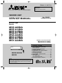
SPLIT-TYPE, HEAT PUMP AIR CONDITIONERS
INDOOR UNIT
No. OB450
SERVICE MANUAL
REVISED EDITION-A
Wireless type
Models
MSZ-A09NA
MSZ-A12NA
MSZ-A15NA
MSZ-A17NA
MSZ-A24NA
MSY-A15NA
MSY-A17NA
MSY-A24NA
Outdoor unit service manual
MUZ-A·NA Series (OB451)
MXZ-A·NA Series (OB444)
CONTENTS
MSZ-A09NA MSY-A15NA
MSZ-A12NA MSY-A17NA
MSZ-A15NA
MSZ-A17NA
1. TECHNICAL CHANGES ····································2
2. PART NAMES AND FUNCTIONS······················3
3. SPECIFICATION·················································4
4. OUTLINES AND DIMENSIONS ·························6
5. WIRING DIAGRAM ············································8
6. REFRIGERANT SYSTEM DIAGRAM ················9
7. SERVICE FUNCTIONS ····································10
8. TROUBLESHOOTING······································11
9. DISASSEMBLY INSTRUCTIONS ····················25
10. PARTS LIST······················································30
10-1. PARTS LIST·············································30
10-2. RoHS PARTS LIST ··································36
11. MICROPROCESSOR CONTROL·····················42
NOTE:
This service manual describes technical data of the intdoor units.
RoHS compliant products have <G> mark on the spec name plate.
For servicing of RoHS compliant products, refer to the PARTS
LIST (RoHS compliant).
OB450-1.qxp
06.11.29 1:37 PM
Page 2
Revision A:
• PARTS LIST has been revised. (10-1.8, 10-2.8)
1
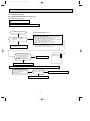
TECHNICAL CHANGES
MSZ09UN
MSZ12UN
MSH15TN
MSH17TN
MSH24WN
MS15TN
MS17TN
MS24WN
➔
➔
➔
➔
➔
➔
➔
➔
MSZ-A09NA
MSZ-A12NA
MSZ-A15NA
MSZ-A17NA
MSZ-A24NA
MSY-A15NA
MSY-A17NA
MSY-A24NA
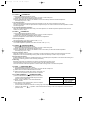
1.Control method between indoor and outdoor has been changed.
2.Indoor fan motor has been changed.
3.Signal of remote controller has been changed. (It is not available for conventional models.)
2
OB450-1.qxp
06.11.29 1:37 PM
2
Page 3
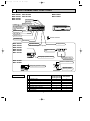
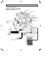
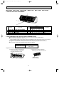
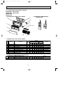
PART NAMES AND FUNCTIONS
MSZ-A09NA
MSZ-A12NA
MSZ-A15NA
MSZ-A17NA
MSY-A15NA
MSY-A17NA
MSZ-A24NA
MSY-A24NA
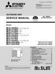
Front panel
Air inlet
Heat exchanger
Panel
Air cleaning filter
(Anti-Allergy Enzyme
Filter, Blue bellows
type)
Catechin air filter
Air outlet
Vertical vane
Remote controller
Horizontal vane
Line flow fan
MSZ-A09NA
MSZ-A12NA
MSZ-A15NA
MSZ-A17NA
MSY-A15NA
MSY-A17NA
Display section
Operation section
(When the front panel is opened)
Operation Indicator
lamp
Emergency operation switch
MSZ-A24NA
MSY-A24NA
Remote control
receiving section
Operation indicator lamp
Emergency operation switch
Remote control
receiving section
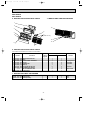
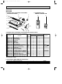
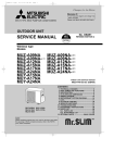
ACCESSORIES
1
2
3
4
5
6
7
8
MSZ-A09NA MSZ-A17NA
MSZ-A12NA MSY-A15NA
MSZ-A15NA MSY-A17NA
1
Installation plate
8
Installation plate fixing screw 4 o 25 mm
1
Remote controller holder
2
Fixing screw for 3 o 3.5 o 1.6 mm (Black)
2
Battery (AAA) for remote controller
1
Wireless remote controller
1
Felt tape (Used for left or left-rear piping)
1
Conduit plate
3
MSZ-A24NA
MSY-A24NA
1
7
1
2
2
1
1
–
OB450-1.qxp
3
06.11.29 1:37 PM
Page 4
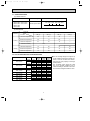
SPECIFICATION
Model
Item
INDOOR UNIT MODEL
External finish
Power supply
V, phase, Hz
Max.-fuse size (time delay)/ Disconnect switch
A
Min. circuit ampacity
A
Fan motor
F.L.A
CFM
Airflow Low—Med.—High HEAT Dry
CFM
COOL Dry (Wet)
Moisture removal
pt./h
Sound level Low-Med.-High
dB(A)
Cond. drain connection O.D.
in.
in.
W
Dimensions
in.
D
in.
H
Weight
Ib.
REMOTE CONTROLLER
Control voltage (by built-in transformer)
MSZ-A12NA
MSZ-A12NA
MSZ-A09NA
MSZ-A09NA
White
208/230, 1, 60
15
1.0
0.76
307-222-159
307(275)-229(205)-152(134)
2.3
22-33-38
1.0
0.76
353-240-159
353(318)-240(215)-152(134)
3.2
22-34-42
5/8
30-11/16
8-1/4
11-3/4
23
23
Wireless type
12-24V DC
Model
MSZ-A17NA
MSY-A17NA
MSZ-A15NA
MSY-A15NA
Item
INDOOR UNIT MODEL
MSZ-A15NA
MSY-A15NA
MSZ-A17NA
MSY-A17NA
External finish
White
Power supply
V, phase, Hz
208/230, 1, 60
Max.-fuse size (time delay)/ Disconnect switch
A
15
Min. circuit ampacity
A
1.0
1.0
Fan motor
F.L.A
0.76
0.76
CFM
381-314-254
—
381-314-254
—
Airflow Low—Med.—High HEAT Dry
CFM
COOL Dry (Wet)
381(342)-328(293)-268(240)
381(342)-328(293)-268(240)
Moisture removal
pt./h
4.7
5.1
Sound level Low-Med.-High (Cooling/Heating) dB(A) 34-40-45/34-38-44
34-40-45/ —
34-40-46/34-38-44
34-40-46/ —
Cond. drain connection O.D.
in.
5/8
in.
30-11/16
W
Dimensions
in.
8-1/4
D
in.
11-3/4
H
Weight
Ib.
23
23
REMOTE CONTROLLER
Wireless type
Control voltage (by built-in transformer)
12-24V DC
Model
Item
INDOOR UNIT MODEL
External finish
Power supply
V, phase, Hz
Max.-fuse size (time delay)/ Disconnect switch
A
Min. circuit ampacity
A
Fan motor
F.L.A
CFM
HEAT Dry
Airflow Low—Med.—High
CFM
COOL Dry (Wet)
Moisture removal
pt./h
Sound level Low-Med.-High (Cooling/Heating) dB(A)
Cond. drain connection O.D.
in.
W
in.
Dimensions
D
in.
H
in.
Weight
Ib.
REMOTE CONTROLLER
Control voltage (by built-in transformer)
MSY-A24NA
MSY-A24NA
MSZ-A24NA
MSZ-A24NA
White
208/230, 1, 60
15
1.0
0.76
568-486-296
568(508)-431(385)-296(265)
7.3
34-40-49/34-40-48
1.0
0.76
—
568(508)-431(385)-296(265)
7.3
34-40-49/ —
5/8
43-5/16
10-1/4
12-13/16
37
37
Wireless type
12-24V DC
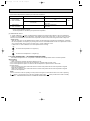
NOTE : Test conditions are based on ARI 210/240.
❈1 : Rating conditions (cooling) — Indoor : 80˚FDB, 67˚FWB, Outdoor : 95˚FDB, (75˚FWB)
(heating) — Indoor : 70˚FDB, 60˚FWB, Outdoor : 47˚FDB, 43˚FWB
❈2 :
(heating) — Indoor : 70˚FDB, 60˚FWB, Outdoor : 17˚FDB, 15˚FWB
4
OB450-1.qxp
06.11.29 1:37 PM
Page 5
3-1. OPERATING RANGE
(1) POWER SUPPLY
Model
Rated voltage
MSZ-A09NA MSY-A15NA
MSZ-A12NA MSY-A17NA
MSZ-A15NA MSY-A24NA
MSZ-A17NA
MSZ-A24NA
208/230V 1phase 60Hz
Guaranteed Voltage
Min. 198V 208V 230V Max. 253V
(2) OPERATION
Intake air
temperature
Function
Outdoor
Indoor
DB (˚F)
WB (˚F)
DB (˚F)
WB (˚F)
Standard temperature
80
67
95
—
Maximum temperature
95
71
115
—
Minimum temperature
67
57
14
—
Condition
Cooling
78%
Maximum humidity
Heating
—
Standard temperature
70
60
47
43
Maximum temperature
80
67
75
65
Minimum temperature
70
60
14
13
3-2. OUTLET AIR SPEED AND COVERAGE RANGE
Model
MSZ-A09NA
Mode
Function
HEAT
Dry
Dry
Wet
Dry
Dry
Wet
Dry
Dry
Wet
Dry
Dry
Wet
Dry
Dry
Wet
COOL
HEAT
MSZ-A12NA
MSZ-A15NA
MSZ-A15NA
MSY-A15NA
MSZ-A17NA
MSZ-A17NA
MSY-A17NA
MSZ-A24NA
MSZ-A24NA
MSY-A24NA
COOL
HEAT
COOL
HEAT
COOL
HEAT
COOL
Air flow Air speed Coverage ● The air coverage range is the figure up
(CFM) (ft./sec.) range (ft.)
to the position where the air speed is 1
23.4
16.8
307
ft./sec., when air is blown out horizon23.4
16.8
307
tally from the unit properly at the High
21.0
15.1
275
speed position.
26.7
19.3
353
The coverage range should be used
26.7
19.3
353
only as a general guideline since it
24.1
17.4
318
varies according to the size of the room
28.8
20.9
381
and furniture arranged inside the room.
28.8
20.9
381
26.0
18.8
342
28.8
20.9
381
28.8
20.9
381
26.0
18.8
342
34.4
20.2
568
34.4
20.2
568
30.9
18.1
508
5
Page 6
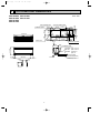
OUTLINES AND DIMENSIONS
MSZ-A09NA MSY-A15NA
MSZ-A12NA MSY-A17NA
MSZ-A15NA
MSZ-A17NA
7/16x13/16 Oblong hole
Installation plate
Indoor unit
8-7/8
2-3/16
7/8 hole
7/8
10-1/8
8-7/16
1-5/8
30-11/16
8-7/8
2-3/16
6-1/8
2-3/16
6-1/8
13-3/16
1-3/4
12-5/8
Air in
8-1/4
11-3/4
24-9/16
3/16
Installation plate
Liquid line [1/4 19-11/16
Gas line [3/8 16-15/16
Insulation [1-3/8 O.D
[3/4 I.D
Drain hose [5/8
(Connected part O.D)
4
Air out
3/4
6-1/4
2-5/16
2-3/4
Wall hole [2-9/16
{
2-1/8
8-7/16
9-3/16
10-3/4
11-5/16
7/16x1 Oblong hole
9/16
Unit : inch
1/8
4
06.11.29 1:37 PM
1-11/16
OB450-1.qxp
6
Insulation [1-1/8
Page 7
Unit : inch
MSZ-A24NA
MSY-A24NA
Installation plate
Indoor unit
3-7/8
5/16
6-13/16
3-7/8
16-5/16
16-5/16
6-13/16
1/8
1-7/8
10-1/16
42-1/16
12-3/8
06.11.29 1:37 PM
1-7/8
OB450-1.qxp
Wall hole [3
10-1/4
43-5/16
Air in
3/16
Installation plate
12-13/16
{
2-3/16
31-1/8
9-15/16
Air out
Drain hose [5/8
(Connected part O.D)
Insulation [1-1/8
3/4
6-1/4
2-5/16
Liquid line [1/4 19-11/16
Gas line [5/8 16-15/16
Insulation [1-15/16 O.D
[1-1/4 I.D
Wireless remote controller
7
OB450-1.qxp
5
06.11.29 1:37 PM
Page 8
WIRING DIAGRAM
MSZ-A09NA MSY-A15NA
MSZ-A12NA MSY-A17NA
MSZ-A15NA
MSZ-A17NA
MSZ-A24NA
MSY-A24NA
8
OB450-1.qxp
06.11.29 1:37 PM
6
Page 9
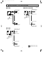
REFRIGERANT SYSTEM DIAGRAM
MSZ-A09NA
MSZ-A12NA
MSZ-A15NA MSY-A15NA
MSZ-A17NA MSY-A17NA
Refrigerant pipe [1/2
(with heat insulator)
Refrigerant pipe [3/8
(with heat insulator)
Indoor coil
thermistor
RT12(main)
Indoor
heat
exchanger
Unit:inch
Indoor
heat
exchanger
Flared connection
Indoor coil
thermistor
RT12(main)
Distributor
Flared connection
Indoor coil
thermistor
RT13(sub)
Indoor coil
thermistor
RT13(sub)
Room temperature
thermistor
RT11
Room temperature
thermistor
RT11
Flared connection
Flared connection
Refrigerant pipe [1/4
(with heat insulator)
Refrigerant pipe[1/4
(with heat insulator)
MSZ-A24NA
MSY-A24NA
Indoor
heat
exchanger
Refrigerant pipe [5/8
(with heat insulator)
Indoor coil
thermistor
RT12(main)
Distributor
Flared connection
Indoor coil
thermistor
RT13(sub)
Room temperature
thermistor
RT11
Flared connection
Refrigerant flow in cooling
Refrigerant pipe [1/4
(with heat insulator)
Refrigerant flow in heating
9
OB450-1.qxp
7
06.11.29 1:37 PM
Page 10
SERVICE FUNCTIONS
MSZ-A09NA MSZ-A12NA MSZ-A15NA MSZ-A17NA MSZ-A24NA
MSY-A15NA MSY-A17NA MSY-A24NA
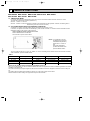
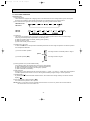
7-1. TIMER SHORT MODE
For service, set time can be shortened by short circuit of JPG and JPS the indoor electronic control P.C. board.
The time will be shortened as follows. (Refer to 8-7.)
Set time : 1-minute ➔ 1-second
Set time : 3-minute ➔ 3-second (It takes 3 minutes for the compressor to start operation. However, the starting time is
shortened by short circuit of JPG and JPS.)
7-2. P.C. BOARD MODIFICATION FOR INDIVIDUAL OPERATION
A maximum of 4 indoor units with wireless remote controllers can be used in a room.
In this case, to operate each indoor unit individually by each remote controller, P.C. boards of remote controller must be
modified according to the number of the indoor unit.
How to modify the remote controller P.C. board
Remove batteries before modification.
The board has a print as shown below :
J1
NOTE : For modification, take out
the batteries and press the
OPERATE/STOP(ON/OFF)
button twice or 3 times at
first.
After finish modification,
put back the batteries then
press the RESET button.
J2
The P.C. board has the print “J1” and “J2”. Solder “J1” and “J2” according to the number of indoor unit as shown in Table 1.
After modification, press the RESET button.
Table 1
1 unit operation
2 units operation
3 units operation
4 units operation
No. 1 unit
No modification
Same as at left
Same as at left
Same as at left
No. 2 unit
–
Solder J1
Same as at left
Same as at left
No. 3 unit
–
–
Solder J2
Same as at left
No. 4 unit
–
–
–
Solder both J1 and J2
How to set the remote controller exclusively for particular indoor unit
After you turn the breaker ON, the first remote controller that sends the signal to the indoor unit will be regarded as the remote
controller for the indoor unit.
The indoor unit will only accept the signal from the remote controller that has been assigned to the indoor unit once they are
set.
The setting will be cancelled if the breaker has turned off, or the power supply has shut down.
Please conduct the above setting once again after the power has restored.
10
OB450-1.qxp
06.11.29 1:37 PM
Page 11
7-3. AUTO RESTART FUNCTION
When the indoor unit is controlled with the remote controller, the operation mode, the set temperature, and the fan speed
are memorized by the indoor electronic control P.C. board. The “AUTO RESTART FUNCTION” sets to work the moment
power has restored after power failure. Then, the unit will restart automatically.
Operation
1 If the main power has been cut, the operation settings remain.
2 After the power is restored, the unit restarts automatically according to the memory.
(However, it takes at least 3 minutes for the compressor to start running.)
How to release “AUTO RESTART FUNCTION”
1Turn off the main power of the unit.
2Solder the Jumper wire JR07 on the indoor electronic control P.C. board. (Refer to 8-7.)
MSZ-A09/12/15/17NA
MSY-A15/17NA
JR07
BZ
JR07
BZ
CN101
CN151
CN112
CN152
CN151
CN112
CN211
CN211
MSZ-A24NA
MSY-A24NA
NOTE:
• The operation settings are memorized when 10 seconds have passed after the indoor unit was operated with the
remote controller.
• If main power is turned OFF or a power failure occurs while AUTO START/STOP timer is active, the timer setting is
cancelled.
• If the unit has been off with the remote controller before power failure, the auto restart function does not work as the
power button of the remote controller is off.
• To prevent breaker off due to the rush of starting current, systematize other home appliance not to turn on at the
same time.
• When some air conditioners are connected to the same supply system, if they are operated before power failure,
the starting current of all the compressors may flow simultaneously at restart.
Therefore, the special counter-measures are required to prevent the main voltage-drop or the rush of the starting
current by adding to the system that allows the units to start one by one.
8
TROUBLESHOOTING
MSZ-A09NA
MSY-A15NA
MSZ-A12NA
MSY-A17NA
MSZ-A15NA MSZ-A17NA
MSY-A24NA
MSZ-A24NA
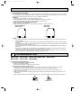
8-1. Cautions on troubleshooting
1. Before troubleshooting, check the following:
1) Check the power supply voltage.
2) Check the indoor/outdoor connecting wire for mis-wiring.
2. Take care of the following during servicing.
1) Before servicing the air conditioner, be sure to turn off the unit first with the remote controller, and then after
confirming the horizontal vane is closed, turn off the breaker and / or disconnect the power plug.
2) Be sure to turn OFF the power supply before removing the front panel, the cabinet, the top panel, and the
electronic control P.C. board.
3) When removing the electronic control P.C. board, hold the edge of the board with care NOT to apply stress on the
components.
4) When connecting or disconnecting the connectors, hold the housing of the connector. DO NOT pull the lead wires.
Lead wiring
Housing point
11
OB450-1.qxp
06.11.29 1:37 PM
Page 12
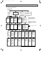
3. Troubleshooting procedure
1) First, check if the OPERATION INDICATOR lamp on the indoor unit is flashing on and off to indicate an abnormality.
To make sure, check how many times the abnormality indication is flashing on and off before starting service work.
2) Before servicing check that the connector and terminal are connected properly.
3) If the electronic control P.C. board is supposed to be defective, check the copper foil pattern for disconnection and the
components for bursting and discoloration.
4) When troubleshooting, refer to 8-2., 8-3. and 8-4.
4. How to replace batteries
Weak batteries may cause the remote controller malfunction.
In this case, replace the batteries to operate the remote controller normally.
2 Press RESET button with tip end of ball point pen
or the like, and then use the remote controller.
1 Remove the front lid and insert batteries.
Then reattach the front lid.
Insert the negative pole of the
batteries first. Check if the polarity
of the batteries is correct.
RESET button
NOTE : 1. If RESET button is not pressed, the remote controller may not operate correctly.
2. This remote controller has a circuit to automatically reset the microcomputer when batteries are replaced.
This function is equipped to prevent the microcomputer from malfunctioning due to the voltage drop caused by
the battery replacement.
INFORMATION FOR MULTI SYSTEM AIR CONDITIONER
OUTDOOR UNIT : MXZ series
Multi system air conditioner can connect two or more indoor units with one outdoor unit.
•Unit won’t operate in case the total capacity of indoor units exceeds the capacity of outdoor units. Do not
connect indoor units beyond the outdoor unit capacity.
Operation indicator lamp flashes as shown in the figure below.
•When you try to operate two or more indoor units with one outdoor unit simultaneously, one for the cooling and
the other for heating, the operation mode of the indoor unit that operates earlier is selected. The other indoor
units cannot operate, indicating as shown in the figure below. In this case, please set all the indoor units to
the same operation mode.
OPERATION INDICATOR
Lighted
Blinking
Not lighted
•When indoor unit starts the operation while the defrosting of outdoor unit is being done, it takes a few minutes
(max. 10 minutes) to blow out the warm air.
•In the heating operation, though indoor unit that does not operate may get warm or the sound of refrigerant
flowing may be heard, they are not malfunction. The reason is that the refrigerant continuously flows into it.
12
OB450-1.qxp
06.11.29 1:37 PM
Page 13
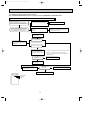
8-2. Failure mode recall function
Outline of the function
This air conditioner can memorize the abnormal condition which has occurred once.
Even though LED indication listed on the troubleshooting check table (8-4.) disappears, the memorized failure details
can be recalled.
This mode is very useful when the unit needs to be repaired for the abnormality which doesn't recur.
1. Flow chart of failure mode recall function for the indoor/outdoor unit
Those figures show about MSZ-A09/12/15/17.
Operational procedure
The cause of abnormality cannot be found because the abnormality doesn't recur.
Setting up the failure mode recall function
Turn ON the power supply.
<Preparation of the remote controller>
1 While pressing both OPERATION SELECT
button and TOO COOL button on the remote controller at the same time, press
RESET button.
2 First, release RESET button.
And release the other two buttons after all LCD in operation display section of the
remote controller is displayed after 3 seconds.
Press OPERATE/STOP(ON/OFF) button of the remote controller (the set temperature
is displayed) with the remote controller headed towards the indoor unit. W1
W1. Regardless of normal or abnormal condition, a short
beep is emitted once as the signal is received.
Does the left lamp of OPERATION INDICATOR
lamp on the indoor unit blink at the interval of 0.5
seconds?
Blinks: Either indoor or outdoor unit is abnormal.
Beep is emitted at the same timing
as the blinking of the left lamp of
OPERATION INDICATOR lamp. W2
Yes
Judgment of indoor/outdoor abnormality
(Blinks)
Before blinking, does the left lamp of
OPERATION INDICATOR lamp stay ON for 3
seconds?
Stays ON for 3 seconds (without beep):
The outdoor unit is abnormal.
No
(OFF)
Indoor unit is normal.
But the outdoor unit might be abnormal because there are some
abnormalities that can't be recalled with this way.
Confirm if outdoor unit is abnormal according to the detailed outdoor
unit failure mode recall function.
Yes
No
The indoor unit is abnormal.
Check the blinking pattern, and confirm the abnormal point with the indoor unit
failure mode table(8-2.2.).
Make sure to check at least two consecutive blinking cycles. W2
The outdoor unit is abnormal.
Check the blinking pattern, and confirm the abnormal point with the
outdoor unit failure mode table (Refer to outdoor unit service manual.)
Make sure to check at least two consecutive blinking cycles. W3
Releasing the failure mode recall function
Release the failure mode recall function by the following procedures.
• Turn OFF the power supply and turn it ON again.
• Press RESET button of the remote controller.
Repair the defective parts.
Deleting the memorized abnormal condition
1After repairing the unit, recall the failure mode again according to
"Setting up the failure mode recall function" mentioned above.
2Press OPERATE/STOP(ON/OFF) button of the remote controller (the set temperature is displayed)
with the remote controller headed towards the indoor unit.
3Press EMERGENCY OPERATION switch so that the memorized abnormal condition is deleted.
4Release the failure mode recall function according to "Releasing the failure mode recall function"
mentioned above.
Note1.Make sure to release the failure mode recall function once it's set up, otherwise the unit cannot operate properly.
2.If the abnormal condition is not deleted from the memory, the last abnormal condition is kept memorized.
W2. Blinking pattern when the indoor unit is abnormal:
Blinking at 0.52.5-second OFF second interval
Blinking at 0.52.5-second OFF second interval
ON
OFF
Beeps
Repeated cycle
Beeps
Repeated cycle
Beeps
Repeated cycle
W3.Blinking pattern when the outdoor unit is abnormal:
Blinking at 0.52.5-second OFF
3-second ON
second interval
2.5-second OFF
3-second ON
Blinking at 0.5second interval
ON
OFF
No beep
Repeated cycle
Beeps
No beep
Repeated cycle
13
Beeps
Repeated cycle
OB450-1.qxp
06.11.29 1:37 PM
Page 14
2. Indoor unit failure mode table
Left lamp of OPERATION
INDICATOR lamp
Not lighted
Abnormal point
(Failure mode)
Condition
Correspondence
Normal
–
–
1-time flash
every 0.5-second
Room temperature
thermistor
The room temperature thermistor short
or open circuit is detected every 8
seconds during operation.
Refer to the characteristics of the room
temperature thermistor (8-7.).
2-time flash
2.5-second OFF
Indoor coil thermistor
The indoor coil thermistor short or open
circuit is detected every 8 seconds during
operation.
Refer to the characteristics of the main
indoor coil thermistor, the sub indoor coil
thermistor (8-7.).
3-time flash
2.5-second OFF
Serial signal
The serial signal from outdoor unit is
not received for a maximum of 6 minutes.
Refer to 8-6.D "How to check mis-wiring
and serial signal error".
11-time flash
2.5-second OFF
Indoor fan motor
The rotational frequency feedback
signal is not emit during the 12 seconds the
indoor fan operation.
Refer to 8-6.A "Check of indoor fan
motor".
12-time flash
2.5-second OFF
Indoor control system
It cannot properly read data in the
nonvolatile memory of the indoor electronic
control P.C. board.
Replace the indoor electronic control
P.C. board.
NOTE : Blinking patterns of this mode differ from the ones of Troubleshooting check table (8-4.).
14
OB450-1.qxp
06.11.29 1:37 PM
Page 15
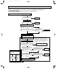
8-3. Instruction of troubleshooting
Start
Indoor unit
operates.
Outdoor unit
doesn't
operate.
Indoor unit operates.
Outdoor unit doesn't
operate normally.
Indoor unit
doesn't receive
the signal from
remote controller.
Outdoor unit
operates only
in Test Run
operation.
w
Outdoor unit
doesn't
operate
even in
Test Run
operation.
w
Unit doesn't
operate
normal
operation in
COOL or
HEAT mode.
Indoor unit
operates, when
EMERGENCY
OPERATION
switch is pressed.
Check room
temperature
thermistor.
Refer to 8-7.
"Test point
diagram and
voltage".
Refer to
"How to check
inverter/
compressor".
Refer to
"Check of
R.V. coil".
Refer to 8-6.B
"Check of
remote controller
and receiver
P.C. board".
Left lamp
3-time flash
Cause:
Indoor unit
• Trouble of
indoor fan
motor
Left lamp
4-time flash
Cause:
Indoor unit
• Trouble of
indoor unit
control
system
Left lamp
Flash on and off
at 0.5-second
intervals
Cause:
Indoor/
Outdoor unit
• Mis-wiring
or trouble
of serial signal
Left lamp
2-time flash
Cause:
Indoor unit
• Trouble of
room temperature/
indoor coil
thermistor
Refer to 8-6.
D "How to
check of
mis-wiring
and serial
signal error".
Check room
temperature
thermistor
and indoor
coil thermistor.
Refer to 8-7.
"Test point
diagram and
voltage".
Refer to 8-6.
A "Check of
indoor fan
motor".
Replace the
indoor
electronic
control
P.C. board.
OPERATION INDICATOR
lamp on the indoor unit is
flashing on and off.
Indoor unit
doesn't operate,
when
EMERGENCY
OPERATION
switch is pressed.
1. Check indoor / outdoor
connecting wire.
(Check if the power
is supplied to the
indoor unit.)
2. Refer to 8-6.C
"Check of indoor
electronic control
P.C. board and indoor
fan motor".
If blinking of OPERATION
INDICATOR lamp cannot be
checked, it can be checked with
failure mode recall function.
w
"Test Run operation" means the
operation within 30 minutes after
EMERGENCY OPERATION switch
is pressed.
Refer to outdoor unit service manual.
Left lamp
5-time flash
Cause:
Outdoor unit
• Outdoor
power
system
abnormality
Left lamp
6-time flash
Cause:
Outdoor unit
• Trouble of
thermistor
in outdoor
unit
Left lamp
7-time flash
Cause:
Outdoor unit
• Trouble of
outdoor
control
system
Left lamp
14-time flash
Cause:
Outdoor unit
• Other
abnormality
Refer to
"How to check
inverter/
compressor".
Refer to
"Check of
outdoor
thermistors".
Replace the
inverter P.C.
board or
the outdoor
electronic
control P.C.
board.
Check
"Flow chart of
the detailed
outdoor unit
failure mode
recall function."
15
OB450-1.qxp
06.11.29 1:37 PM
Page 16
8-4. Troubleshooting check table
Before taking measures, make sure that the symptom reappears for accurate troubleshooting.
When the indoor unit has started operation and the following detection method has detected an abnormality (the first
detection after the power ON), the indoor electronic control P.C. board turns OFF the indoor fan motor with
OPERATION INDICATOR lamp flashing.
Lighted
OPERATION INDICATOR
No.
Abnormal
point
1
Mis-Wiring
or serial
signal
Blinking
Not lighted
· Flashing of OPERATION INDICATOR lamp (left-hand side lamp)
indicates abnormalities.
Operation indicator lamp
Left lamp flashes.
0.5-second ON
Condition
Symptom
Indoor unit
and outdoor
unit do not
operate.
The serial signal from the outdoor unit is not
received for a maximum of 6 minutes.
Correspondence
• Refer to 8-6.D "How to check
mis-wiring and serial signal
error".
0.5-second OFF
Outdoor
control
system
2
3
4
MSZ-A09/12
MSZ-A15/17
MSY-A15/17
Left lamp lights up
Indoor coil
thermistor
Left lamp flashes.
2-time flash
Room
temperature
thermistor
Indoor fan
motor
Outdoor unit
does not
operate.
Indoor unit
and outdoor
unit do not
operate.
It cannot properly read data in the nonvolatile
memory of the inverter P.C. board or the
outdoor electronic control P.C. board.
The indoor coil or the room temperature
thermistor is short or open circuit.
• Refer to 8-7.the
characteristics of indoor coil
thermistor, and the room
temperature thermistor.
The rotational frequency feedback signal is
not emitted during the indoor fan operation.
• Refer to 8-6.A "Check of
indoor fan motor".
Indoor unit
and outdoor
unit do not
operate.
It cannot properly read data in the nonvolatile
memory of the indoor electronic control P.C.
board.
• Replace the indoor electronic
control P.C. board.
Indoor unit
and outdoor
unit do not
operate.
It consecutively occurs 3 times that the
compressor stops for overcurrent protection or
start-up failure protection within 1 minute after
start-up.
• Refer to "How to check of
inverter/ compressor".
Refer to outdoor unit service
manual.
• Check the stop valve.
Indoor unit
and outdoor
unit do not
operate.
The outdoor thermistors short or open circuit
during the compressor operation.
• Refer to "Check of outdoor
thermistor".
Refer to outdoor unit service
manual.
Indoor unit
and outdoor
unit do not
operate.
It cannot properly read data in the nonvolatile
memory of the inverter P.C. board or the
outdoor electronic control P.C. board.
• Replace the inverter P.C.
board or the outdoor
electronic control P.C. board.
Refer to outdoor unit service
manual.
Indoor unit
and outdoor
unit do not
operate.
An abnormality other than above mentioned is
detected.
• Confirm the abnormality in
detail using the failure mode
recall function for outdoor
unit.
2.5-second OFF
Left lamp flashes.
3-time flash
• Check the blinking pattern of
the LED on the inverter P.C.
board or the outdoor
electronic
control P.C. board.
Indoor unit
and outdoor
unit do not
operate.
2.5-second OFF
5
Indoor
control
system
Left lamp flashes.
4-time flash
2.5-second OFF
6
Outdoor
power
system
Left lamp flashes.
5-time flash
2.5-second OFF
Left lamp flashes.
6-time flash
7
Outdoor
thermistors
2.5-second OFF
8
Outdoor
control
system
Left lamp flashes.
7-time flash
2.5-second OFF
9 Other
abnormality
Left lamp flashes.
14-time flash
2.5-second OFF
16
OB450-1.qxp
06.11.29 1:37 PM
Page 17
OPERATION INDICATOR
Lighted
Blinking
Not lighted
No.
1
Abnormal
point
MXZ type
Operation
mode
setting
· Flashing of OPERATION INDICATOR lamp (right-hand side lamp) indicates
abnormality.
· OPERATION INDICATOR lamp (left-hand side lamp) is lighted.
Operation indicator lamp
Right lamp flash
2.5-second OFF
Symptom
Condition
Correspondence
Outdoor unit
operates but
indoor unit
does not
operate.
The operation mode of the each indoor
unit is differently set to COOL(includes DRY)
and HEAT at the same time, the operation
mode of the indoor unit that has operated at
first has the priority.
• Unify the operation mode.
Refer to outdoor unit service
manual.
8-5. Trouble criterion of main parts
MSZ-A09NA MSZ-A12NA MSZ-A15NA
MSZ-A17NA MSZ-A24NA
MSY-A15NA MSY-A17NA MSY-A24NA
Part name
Room temperature
thermistor(RT11)
Indoor coil thermistor
(RT12(MAIN), RT13(SUB))
Indoor fan motor(MF)
Horizontal vane
motor(MV)
MSZ-A09/12/15/17NA
MSY-A15/17NA
Horizontal vane
motor(MV1)
Vertical vane
motor(MV2)
MSZ-A24NA
MSY-A24NA
Check method and criterion
Figure
Measure the resistance with a tester.
Refer to 8-7. "Test point diagram and voltage",
"Indoor electronic control P.C. board", the chart of thermistor.
Check 8-6. A.
Measure the resistance between the terminals with a tester.
(Part temperature 50°F ~ 86°F)
Color of the lead wire
BRN-other one
Normal
235 " ~ 255 "
Measure the resistance between the terminals with a tester.
(Part temperature 50°F ~ 86°F)
Color of the lead wire
BRN-other one
Normal
282 " ~ 306 "
17
RED
ROTOR
YLW
BRN
ORN
GRN
RED
ROTOR
YLW
BRN
ORN
GRN
OB450-1.qxp
06.11.29 1:37 PM
Page 18
8-6. Troubleshooting flow
When OPERATION INDICATOR lamp flashes 3-time.
Indoor fan does not operate.
A Check of indoor fan motor
The indoor fan motor error has occurred, and the indoor fan doesn't operate.
Turn OFF the power supply.
Pay careful attention to the high voltage on
the fan motor connector CN211.
Is there any foreign matter that
interferes the rotation of the
line flow fan?
Turn ON the power supply, wait 5 seconds or more, and then press
EMERGENCY OPERATION switch.
Measure the supply voltage as follows within 12 seconds
after EMERGENCY OPERATION switch is pressed.
If more than 12 seconds passes by, turn OFF the power supply and
turn ON it again, then measure the voltage. w
1.Measure the voltage between CN211 1(+) and 3(-).
2.Measure the voltage between CN211 5(+) and 3(-).
No
Yes
w If more than 12 seconds or more passes after EMERGENCY OPERATION
switch is pressed, the voltage mentioned above 2 goes 0V DC although
the indoor electric control P.C. board is normal.
Remove the foreign matter and
adjust the line flow fan.
Is there 294/325V DC between
CN211 1 (+) and 3 (-), and does
the voltage between CN211 5(+)
and 3(-) rise to the range of 3 to 6V
DC within 12 seconds after
EMERGENCY OPERATION switch
is pressed?
CN211
Yes
Replace the indoor fan motor.
Indoor electronic
control P.C. board
No
Replace the indoor electronic control P.C. board.
The indoor fan motor error has occurred, and the indoor fan repeats "12-second ON and 30-second OFF" 3times, and then stops.
Measure the voltage between CN211
6(+) and 3(-) while the fan
motor is rotating.
Is it unchanged holding
0V DC or 15V DC?
No
(Changed)
Yes
(Unchanged)
Replace the indoor fan motor.
18
Replace the indoor electronic control P.C. board.
OB450-1.qxp
06.11.29 1:37 PM
Page 19
Indoor unit operates by pressing EMERGENCY OPERATION switch, but does not operate with the remote controller.
B Check of remote controller and receiver P.C. board
wCheck if the remote controller is exclusive for this air conditioner.
Switch ON the remote controller.
Is LCD display on the the remote
controller visible?
No
Replace the batteries. (Refer to 8-1.4.)
(not clear)
Yes
Remove the batteries, then set them back
and press RESET button. (Refer to 8-1.4.)
Check if the unit operates with the remote
controller.
Does the unit operate with the
remote controller?
No
Turn ON a radio to AM and press switch
ON the remote controller.
Yes
No
Is noise heard from radio?
OK
Replace the remote controller.
Yes
Are there any fluorescent lights of
inverter or rapid-start type within
the range of 3.28ft.?
Yes
● Reinstall the unit away from lights.
● Attach a filter on receiving part.
No
MSZ-A24NA
MSY-A24NA
MSZ-A09/12/15/17NA
MSY-A15/17NA
Measure the voltage between receiver P.C. board
connector CN301 No.2(+) and No.3(-) when the
remote controller button is pressed.
Yes
Replace the indoor electronic control P.C.
board.
Is the voltage approx. 4V DC?
No (5V or 0V DC)
Replace the receiver P.C. board.
19
OB450-1.qxp
06.11.29 1:37 PM
Page 20
The unit does not operate with the remote controller.
Also, OPERATION INDICATOR lamp does not light up by pressing EMERGENCY OPERATION switch.
C Check of indoor electronic control P.C. board and indoor fan motor
Turn OFF the power supply.
Remove indoor fan motor connector CN211 and
vane motor connector CN151 from the indoor electronic
control P.C. board and turn ON the power supply.
Measure the resistance between CN211 3
and 4 of the indoor fan motor connector.
Short/open circuit:
Replace the indoor fan motor.
Yes
Does the unit operate with the remote controller?
Does OPERATION INDICATOR lamp light up by
pressing EMERGENCY OPERATION switch?
Measure the resistance of the horizontal vane
motor coil.
Refer to 8-5.
Short/open circuit:
Replace the horizontal vane motor and the indoor
electronic control P.C. board.
No
Replace the indoor electronic
control P.C. board.
Yes
Are the varistor(NR11) burnt
and the fuse(F11) blown?
Turn OFF the power supply.
Check both “parts side” and “pattern
side” of the indoor electronic control P.C.
board visually.
No
Be sure to check both the fuse
and the varistor in any case.
No
Is the fuse(F11) blown only?
Yes
Measure the resistance between
1(+) and 3(-) of the indoor fan
motor connector (to CN211 on the
indoor electronic control P.C. board) .
w1,w2
No
Is the resistance 1M"
or more?
w1. The fan motor connector's 1 lead wire is red, whereas 3 is black.
w2. Connect "+" of the tester to fan motor connector's 1 lead
wire, and "-" to 3 lead wire, otherwise the resistance cannot be
measured properly.
Replace the indoor electronic control
P.C. board and the indoor fan motor.
Yes
Replace the indoor electronic
control P.C. board
Measure the resistance of cement
resistance R111 on the indoor electronic
control P.C. board.
Is the resistance
approx. 4"?
No
Yes
Replace the indoor electronic control P.C. board.
Indoor electronic
control P.C.Board
Varistor(NR11)
Fuse(F11)
CN211
20
Replace the indoor electronic control P.C. board
and the indoor fan motor.
OB450-1.qxp
06.11.29 1:37 PM
Page 21
• When unit cannot operate neither by the remote controller nor by EMERGENCY OPERATION switch.
Indoor unit does not operate.
• When OPERATION INDICATOR lamp flashes ON and OFF in every 0.5-second.
Outdoor unit does not operate.
D How to check mis-wiring and serial signal error
Turn OFF the power supply.
Is there rated voltage AC
in the power supply?
No
Check the power
supply.
Yes
Turn ON the power supply.
Is there rated voltage between
outdoor terminal block S1 and
S2?
No
Check the wiring.
Yes
Press EMERGENCY OPERATION switch once.
Does the left lamp of OPERATION INDICATOR
lamp light up?
<Confirmation of the power to the indoor unit>
Yes
Is serial signal error indicated 6 minutes later?
No
No
Yes
Is there any mis-wiring,
poor contact, or wire
disconnection of the
indoor/outdoor
connecting wire?
Yes
Make them correct.
No
A
Turn OFF the power supply.
Check once more if the indoor/outdoor
B connecting wire is not mis-wiring.
Short-circuit outdoor terminal block S2 and
S3.
W1
Turn ON the power supply.
W1. Mis-wiring may damage indoor electronic control
P.C. board during the operation.
Be sure to confirm the wiring is correct before the
operation starts.
W3.Be sure to check this within 3 minutes after turning
ON. After 3 minutes, LED blinks 6 times. Even when
the inverter P.C.board or the outdoor electronic control
P.C.board is normal, LED blinks 6 times after
3 minutes.
(Except for outdoor unit of multi system type)
Does the LED on the inverter P.C. board
Replace the inverter P.C. board or
No
or the outdoor electronic control P.C.board
the outdoor electronic control P.C.board.
repeat "3.6-second-OFF and 0.8-second-ON
(Lighted or W2
quick blinking"? W3
not lighted)
W2 Be careful to the residual
voltage of smoothing capacitor.
Yes
A
· Turn OFF inverter-controlled lighting
equipment.
· Turn OFF the power supply and then
turn ON again.
· Press EMERGENCY OPERATION
switch.
Is serial signal
error indicated
6 minutes later?
Yes
B
· Reinstall
either the
unit or the
light each
other away.
No
· Attach a filter
on remote
control
receiving
section of
the indoor
unit.
Turn OFF the power supply.
Remove the short-circuit between
outdoor terminal block S2 and S3.
Turn ON the power supply.
Is there amplitude of 10 to 20V DC
between outdoor terminal block S2
and S3? <Confirmation of serial
signal>
No
Is there any error of the
indoor/outdoor connecting wire,
such as the damage of the wire,
intermediate connection, poor
contact to the terminal block?
Yes
Replace the
indoor/outdoor
connecting wire.
No
Yes
Is there rated voltage between
indoor terminal block S1 and S2?
<Confirmation of power voltage>
No
Is there any error of the
indoor/outdoor connecting wire,
such as the damage of the wire,
intermediate connection, poor
contact to the terminal block?
Yes
No
Replace the indoor electronic control P.C. board.
Be sure to release the failure-mode
recall function after checking.
Refer to outdoor unit service manual.
21
Yes Replace the
indoor/outdoor
connecting wire.
OB450-1.qxp
06.11.29 1:37 PM
Page 22
E Electromagnetic noise enters into TV sets or radios
No
Is the unit grounded?
Ground the unit.
Yes
Is the distance between the
antennas and the indoor
unit within 9.91ft., or is the
distance between the
antennas and the outdoor
unit within 9.91ft.?
Extend the distance between
the antennas and the indoor
unit, and/or the antennas and
the outdoor unit.
Yes
No
Is the distance between the
TV sets or radios and the
indoor unit within 3.28ft., or is
the distance between the TV
sets or radios and the
outdoor unit within 9.91ft.?
Extend the distance between
the TV sets and/or radios and
the indoor unit, or the TV sets
or radios and the outdoor unit.
Yes
No
Are the antennas damaged?
Is the coaxial cable damaged?
Is there any poor contact in
the antenna wiring?
Yes
Replace or repair the antenna.
Replace or repair the coaxial cable.
No
Is the indoor/outdoor
connecting wire of the air
conditioner and the wiring of
the antennas close?
Extend the distance between
the indoor/outdoor connecting
wire of the air conditioner and
the wiring of the antennas.
Yes
No
Even if all of the above conditions is fulfilled, the electromagnetic noise may enter, depending on
the electric field strength or the installation condition (combination of specific conditions such as
antennas or wiring).
Check the followings before asking for service.
1.Devices affected by the electromagnetic noise
TV sets, radios (FM/AM broadcast, shortwave)
2.Channel, frequency, broadcast station affected by the electromagnetic noise
3.Channel, frequency, broadcast station unaffected by the electromagnetic noise
4.Layout of ;
indoor/outdoor unit of the air conditioner, indoor/outdoor wiring, grounding wire, antennas, wiring
from antennas, receiver
5.Electric field intensity of the broadcast station affected by the electromagnetic noise
6.Presence or absence of amplifier such as booster
7.Operation condition of air conditioner when the electromagnetic noise enters in.
1)Turn OFF the power supply once, and then turn ON the power supply. In this situation check for
the electromagnetic noise.
2)Within 3 minutes after turning ON the power supply, press OPERATE/STOP (ON/OFF) button
on the remote controller for power ON, and check for the electromagnetic noise.
3)After a short time (3 minutes later after turning ON), the outdoor unit starts running. During
operation, check for the electromagnetic noise.
4)Press OPERATE/STOP (ON/OFF) button on the remote controller for power OFF, when the
outdoor unit stops but the indoor/outdoor communication still runs on. In this situation check for
the electromagnetic noise.
After checking the above, consult the service representative.
22
OB450-1.qxp
06.11.29 1:37 PM
Page 23
8-7. Test point diagram and voltage
MSZ-A09NA
MSZ-A17NA
MSZ-A12NA
MSY-A15NA
MSZ-A15NA
MSY-A17NA
Indoor electronic control P.C. board
Power supply input
208/230V AC
Fuse(F11)
}
Varistor (NR11)
Indoor fan motor
(CN211)
1294/325V DC
3(-) Fiducial terminal of
cathode side on measuring high-voltage DC
415V DC
5(+)3-6V DC
6(+)0V DC or 15V DC
Release of Auto restart
function
Solder the Jumper wire
to JR07
(Refer to 7-3.)
5V DC
Indoor coil thermistor
RT12(MAIN) 12
RT13(SUB) 34
(CN112)
Horizontal vane
motor(CN151)
Room temperature
thermistor(RT11)
}
Power monitor
receiver P.C.
board
Timer short mode
point JPG, JPS
(Refer to 7-1.)
12V DC
Emergency
operation switch
Resistance (k")
Indoor coil thermistor [RT12 (MAIN), RT13 (SUB)]
Room temperature thermistor (RT11)
SW P.C. board
Temperature (˚F)
23
OB450-1.qxp
06.11.29 1:37 PM
MSZ-A24NA
Page 24
MSY-24NA
Indoor electronic control P.C. board
Varistor (NR11)
Power supply input
208/230V AC
Fuse(F11)
}
Release of Auto restart
function
Solder the Jumper wire
to JR07
(Refer to 6-3.)
Indoor fan motor
(CN211)
1294/325V DC
3(-) Fiducial terminal of
cathode side on measuring high-voltage DC
415V DC
Display
P.C.
board
5(+)3-6V DC
6(+)0V DC or 15V DC
5V DC
Indoor coil thermistor
RT12(MAIN)
RT13(SUB)
Horizontal vane
motor(CN151)
Room temperature
thermistor(RT11)
}
12V DC
Receiver
P.C. board
Timer short
mode point
JPG, JPS
(Refer to 7-1.)
Vertical vane motor (CN152)
Indoor coil thermistor [RT12 (MAIN), RT13 (SUB)]
Room temperature thermistor (RT11)
Resistance (k")
SW P.C. board
Temperature (F˚)
24
OB450-1.qxp
06.11.29 1:37 PM
9
Page 25
DISASSEMBLY INSTRUCTIONS
<"Terminal with locking mechanism" Detaching points>
The terminal which has the locking mechanism can be detached as shown below.
There are two types ( Refer to (1) and (2)) of the terminal with locking mechanism.
The terminal without locking mechanism can be detached by pulling it out.
Check the shape of the terminal before detaching.
(1) Slide the sleeve and check if there is a locking lever or not.
(2) The terminal with this connector has the
locking mechanism.
Sleeve
Locking lever
1Slide the sleeve.
2Pull the terminal while
pushing the locking
lever.
9-1. MSZ-A09NA MSZ-A12NA MSZ-A15NA
1Hold the sleeve, and
pull out the terminal
slowly.
Connector
MSZ-A17NA MSY-A15NA MSY-A17NA
PHOTOS
OPERATING PROCEDURE
1. Removing the panel
Photo 1
(1) Remove the horizontal vane.
(2) Remove the screw caps of the panel.
Remove the screws. (See Photo 1.)
(3) Hold the lower part of both ends on the panel and pull it
slightly toward you, and then remove the panel by pushing
it upward.
Screws of the panel
Horizontal vane
Photo 2
Terminal block
cover
Conduit cover
Screw of the
conduit cover
Conduit plate
25
OB450-1.qxp
06.11.29 1:38 PM
Page 26
OPERATING PROCEDURE
PHOTOS
2. Removing the electronic control P.C. board, the
power monitor receiver P.C. board, SW P.C. board
and the terminal block
Photo 3
(1) Remove the horizontal vane, the panel (Refer to 1.) and
the corner box.
(2) Remove the screw of the conduit cover, and conduit cover.
(See Photo 2.)
(3) Remove the indoor/outdoor connecting wire.
(4) Remove the switch holder from the electrical cover.
(See Photo 3.)
(5) Remove the screw of the electrical cover, and then the
electrical cover. (See Photo 3.)
(6) Remove the ground wire connected to the indoor
electronic control P.C. board from the electrical box.
(See Photo 4.)
(7) Unhook the power monitor receiver P.C. board holder from
the catch. (See Photo 3.)
(8) Open the rear cover of the power monitor receiver P.C.
board holder and pull out the power monitor receiver P.C.
board.
(9) Open the switch holder and pull out SW P.C. board.
(10) Pull the electronic control P.C. board slightly toward you
from the electrical box, and disconnect TAB3 and all the
connectors on the electronic control P.C. board.
(LD101 and LD105 are direct-mounted to the electronic
control P.C. board.)
(11) Pull out the electronic control P.C. board from the electrical
box.
(12) Remove the ground wire connected to the heat exchanger
from the electrical box. (See Photo 4.)
(13) Unhook the catches of the electrical box, and pull out the
electrical box.
(14) Remove the screw of the terminal block cover, and then
remove the terminal block cover and the terminal block
holder. (See Photo 5)
(15) Remove the terminal block by sliding it.
Switch holder
Screw of the
electrical cover.
Power monitor
receiver
P.C. board holder
Photo 4
Ground wire
Indoor fan motor
connector (CN211)
Indoor coil thermistor
connector (CN112)
Vane motor
connector (CN151)
Photo 5
3. Removing the electrical box
(1) Remove the horizontal vane, the panel (Refer to 1.) and
the corner box.
(2) Remove the screw of Conduit cover, and then the indoor/
outdoor connecting wire. (See Photo 2.)
(3) Remove the switch holder and the electrical cover.
(See Photo 3.)
(4) Remove the ground wire connected to the heat exchanger
from the electrical box. (See Photo 4.)
(5) Disconnect the following connectors on the electronic
control P.C. board; the fan motor connector <CN211>, the
indoor coil thermistor connector <CN112>, the vane motor
connector <CN151>.
(6) Unhook the catches of the electrical box, and pull out the
electrical box.
Screw
26
OB450-1.qxp
06.11.29 1:38 PM
Page 27
OPERATING PROCEDURE
PHOTOS
Photo 6
4. Removing the horizontal vane motor unit
(1) Remove the horizontal vane and the panel. (Refer to 1.)
(2) Remove the screws of the horizontal vane motor unit,
and pull out the horizontal vane motor unit. (See Photo 6.)
(3) Disconnect the connector from the horizontal vane motor
unit.
5. Removing the indoor fan motor and the line flow
fan
(1) Remove the horizontal vane, the panel (Refer to 1.) and
the corner box.
(2) Remove the switch holder and the electrical box. (Refer to 3.)
(3) Remove the drain hose from the nozzle assembly, and
remove the nozzle assembly.
(4) Remove the screws fixing the motor bed. (See Photo 7.)
(5) Loosen the screw fixing the line flow fan. (See Photo 8.)
(6) Remove the motor bed together with fan motor and motor
band.
(7) Release the hooks of the motor band, and remove the
motor band then pull out the indoor fan motor.
(8) Remove the screws fixing the left side of the heat
exchanger. (See Photo 9.)
(9) Lift the heat exchanger, and pull out the line flow fan to the
lower-left.
Screws of the
horizontal vane
motor unit
Photo 7
Screws of
the motor
bed
Photo 8
Screw of
the line
flow fan
Photo 9
Screws of the
left side of the
heat exchanger
27
Motor band
OB450-1.qxp
06.11.29 1:38 PM
Page 28
9-2.MSZ-A24NA MSY-A24NA
OPERATING PROCEDURE
PHOTOS
1. Removing the front panel
(1) Remove the screw caps of the front panel.
Remove the screws.
(2) Pull the panel down to your side slightly and unhook the
catches at the top.
Photo 1
Front panel
Corner box
Screws
2. Removing the electronic control P.C. board, the receiver
P.C. board and the display P.C. board
(1) Remove the front panel. (Refer to 1.)
(2) Remove the corner box
(3) Remove the screw of the electrical cover.
Remove the electrical cover and T.B. SW cover.
(4) Remove the screw of the ground wire, which is soldermounted to the electronic control P.C. board.
(5) Remove the R.L holder.
(6) Remove the screw of the conduit cover.
(7) Remove the conduit cover.
(8) While pulling the electronic control P.C. board forward little
by little, disconnect all the connectors from the board.
(9) Remove the electronic control P.C. board.
(10) Open the R.L holder, remove the receiver P.C. board and
the display P.C. board.
Photo 2
Screw of the ground wire
Indoor
electronic
control
P.C. board
T.B. SW cover
Screw of
T.B. SW cover
Screw of the
electrical cover
Conduit cover
R.L
holder
3. Removing the electrical box
(1) Remove the front panel. (Refer to 1.)
(2) Remove the electrical cover. (Refer to 2.)
(3) Disconnect the connector of the indoor coil thermistors.
(4) Disconnect the indoor fan motor connector (CN211) and
the vane motor connector (CN151 and CN152) on the
electronic control P.C. board.
(5) Remove the screw of ground wire to the heat exchanger.
(6) Remove the fan motor lead wire and indoor coil thermistor
from the electrical box.
(7) Remove the lead wire of vane motor from the bottom of
electrical box.
(8) Remove the screw fixing the electrical box and remove the
electrical box.
28
Photo 3
Screw of
conduit cover
Receiver
P.C. board
Screw of the
ground wire
Screw of the
electrical box
OB450-1.qxp
06.11.29 1:38 PM
Page 29
OPERATING PROCEDURE
PHOTOS
4. Removing the vane motor
(1) Remove the front panel. (Refer to 1.)
(2) Remove the electrical cover. (Refer to 2.)
(3) Remove the lead wire of vane motor.(Refer to 3.)
(4) Remove the R.L. holder.
(5) Pull out the drain hose from the nozzle assembly and
remove the nozzle assembly.
(6) Remove the screws of the vane motor and disconnect the
connector.
(7) Remove the vane motor.
Photo 4
Vane motors
Photo 5
Screws of the
vane motor
Vane motor
5. Removing the line flow fan and the indoor fan motor
(1) Remove the front panel. (Refer to 1.)
(2) Remove the electrical box. (Refer to 3.)
(3) Remove the drain hose from the nozzle assembly and
remove the nozzle assembly.
(4) Remove the water cut.
(5) Slide the hole cover and remove the hole cover.
(6) Remove the hexagon socket set screw from the line flow
fan.
(7) Remove the screws fixing the motor bed and remove the
fan motor. (Be careful not to drop the fan motor because it
is heavy.)
(8) Remove the screws fixing the left side of the heat
exchanger.
(9) Lift the left side of the heat exchanger.
(10) Remove the line flow fan.
Photo 6
Screws fixing
the left side
of the heat
exchanger
Photo 7
Water cut
Photo 8
Hole
cover
Screws of the motor bed
29
Screws
of the
vane
motor
OB450-1.qxp
06.11.29 1:38 PM
10
Page 30
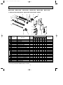
PARTS LIST
10-1. PARTS LIST (non-RoHS compliant)
MSZ-A09NA MSY-A15NA
MSZ-A12NA MSY-A17NA
MSZ-A15NA
MSZ-A17NA
1. INDOOR UNIT STRUCTURAL PARTS
2. ACCESSORY AND REMOTE
CONTROLLER
9
1
12
11
10
8
2
7
(See 10-5.)
3
4
5
6
1. INDOOR UNIT STRUCTURAL PARTS
No.
1
2
3
4
5
6
7
8
9
10
Part No.
E02
E02
E02
E02
E02
E02
A32
A49
913
915
915
916
Part name
234
000
067
010
100
100
BOX
PANEL ASSEMBLY
SCREW CAP
FRONT PANEL
CATECHIN AIR FILTER (LEFT)
CATECHIN AIR FILTER (RIGHT)
AIR CLEANING FILTER
E02 A32 975 CORNER BOX (RIGHT)
E02 913 970 INSTALLATION PLATE
E02 A49 978 CONDUIT PLATE
Q'ty/unit
Symbol
MSZMSYin Wiring
Remarks
Diagram A09NA A12NA A15NA A17NA A15NA A17NA
1
1
1
1
1
1
1 Including No.3,4
1
1
1
1
1
2 2PCS/SET
2
2
2
2
2
1
1
1
1
1
1
1
1
1
1
1
1
1
1
1
1
1
1
1 MAC-415FT-E
1
1
1
1
1
1
1
1
1
1
1
1
1
1
1
1
1
1
1
1
1
1
1
2. ACCESSORY AND REMOTE CONTROLLER
11
12
E02 A54 426 REMOTE CONTROLLER
E02 A49 426 REMOTE CONTROLLER
E02 527 083 REMOTE CONTROLLER HOLDER
1
1
30
1
1
1
1
1
1
1
1
1
1
KM06A
KM06C
OB450-2.qxp
06.11.29 1:40 PM
MSZ-A09NA
Page 31
MSZ-A12NA
MSZ-A15NA
MSZ-A17NA
MSY-A15NA
MSY-A17NA
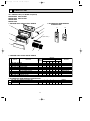
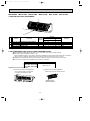
3. INDOOR UNIT ELECTRICAL PARTS AND FUNCTIONAL PARTS
1
18
17
15
16
14
2
3
4
5
6
11
10
9
12
No.
1
2
3
4
5
6
7
8
9
10
11
12
13
14
15
16
17
18
Part No.
E02
E02
E02
E02
E02
E02
E02
E02
E02
E02
E02
E02
E02
E02
E02
E02
E02
E02
E02
E02
E02
E02
E02
E02
E02
751
001
897
A54
A56
897
913
915
A49
A49
A49
913
A54
A55
A56
A57
A51
A52
897
A54
A56
915
A54
897
897
509
504
702
235
235
303
040
095
979
780
779
375
452
452
452
452
452
452
308
307
307
782
300
333
302
8
7
12
13
Q'ty/unit
Symbol
in Wiring
Part name
MSZMSYDiagram A09NA A12NA A15NA A17NA A15NA A17NA
1
1
BEARING MOUNT
1
1
1
1
1
1
SLEEVE BEARING
1
1
1
1
1
1
DRAIN HOSE
1
1
1
1
NOZZLE ASSEMBLY
1
1
1
1
NOZZLE ASSEMBLY
1
1
MV
1
1
VANE MOTOR UNIT (HORIZONTAL)
1
1
1
1
1
1
HORIZONTAL VANE
1
1
1
1
1
1
POWER MONITOR RECEIVER P.C. BOARD HOLDER
1
1
1
1
1
1
CONDUIT COVER
1
1
1
1
1
1
TERMINAL BLOCK COVER
1
1
1
1
1
1
TERMINAL BLOCK HOLDER
1
1
1
1
TB
1
1
TERMINAL BLOCK
1
1
1
1
ELECTRONIC CONTROL P.C. BOARD W1
1
ELECTRONIC CONTROL P.C. BOARD W1
1
1
ELECTRONIC CONTROL P.C. BOARD W1
1
ELECTRONIC CONTROL P.C. BOARD W1
ELECTRONIC CONTROL P.C. BOARD W1
1
ELECTRONIC CONTROL P.C. BOARD W1
1
1
1
ROOM TEMPERATURE THERMISTOR RT11
1
1
1
1
RT12, RT13 1
INDOOR COIL THERMISTOR
1
RT12, RT13
1
1
INDOOR COIL THERMISTOR
1
1
1
1
SWITCH HOLDER
1
1
1
1
MF
1
1
INDOOR FAN MOTOR W2
1
1
1
1
1
1
MOTOR BAND
1
1
1
1
1
1
LINE FLOW FAN
1
1
1
1
W1 Including SW P.C. BOARD and POWER MONITOR RECEIVER P.C. BOARD
W2 Including FAN MOTOR RUBBER MOUNT (2 PCS/SET)
31
Remarks
UP & DOWN
AUTO RESTART
AUTO RESTART
AUTO RESTART
AUTO RESTART
AUTO RESTART
AUTO RESTART
RC0J30-
OB450-2.qxp
06.11.29 1:40 PM
MSZ-A09NA
Page 32
MSZ-A12NA
MSZ-A15NA
MSZ-A17NA
MSY-A15NA
MSY-A17NA
4. INDOOR UNIT HEAT EXCHANGER
1
2
3
No.
1
2
3
Part No.
E02
E02
E02
E02
E02
A54
A56
815
155
151
620
620
666
666
667
Part name
INDOOR HEAT EXCHANGER
INDOOR HEAT EXCHANGER
UNION (GAS)
UNION (GAS)
UNION (LIQUID)
Q'ty/unit
Symbol
MSZMSYin Wiring
Remarks
Diagram A09NA A12NA A15NA A17NA A15NA A17NA
1
1
1
1
1
1
{3/8
1
1
1
1
1
1 {1/2
1
1
1
1
1
1 {1/4
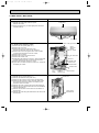
5. AIR CLEANING FILTER (ANTI-ALLERGY ENZYME FILTER)
● AIR CLEANING FILTER removes fine dust of 0.01 micron from air by means of static electricity.
● Normal life of AIR CLEANING FILTER is 1 year.
If AIR CLEANING FILTER is to be washed, soak AIR CLEANING FILTER in water (when showing dirt, in lukewarm
water) and rinse it delicately, without removing the filter from the frame about once every 3 months.
● Clogged AIR CLEANING FILTER may reduce the air conditioner capacity or cause frost on the air outlet.
● Do not remove or attach AIR CLEANING FILTER during unit operation.
Model
MSZ-A09NA MSY-A15NA
MSZ-A12NA MSY-A17NA
MSZ-A15NA MSZ-A17NA
Part No.
MAC-415FT-E
Replacement of the air cleaning filter
(2) Remove the air cleaning filter(Blue
bellows type) from the catechin air filter.
(1) Remove the catechin air filter(left one)
The air cleaning filter is not attached
to the right side catechin air filter
Air cleaning filter
(Blue bellows type)
32
OB450-2.qxp
06.11.29 1:40 PM
Page 33
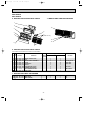
MSZ-A24NA
MSY-A24NA
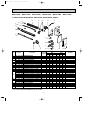
6. INDOOR UNIT STRUCTURAL PARTS
7. INDOOR UNIT HEAT EXCHANGER
1
2
11
3
4
8
5
9
(See 10-10.)
12
13
6
7
6. INDOOR UNIT STRUCTURAL PARTS
Part number that is circled is not shown in the illustration.
No.
Part No.
1
2
3
4
5
6
7
8
9
10
E02 527 970
E02 685 234
E02 888 000
E02 408 142
E02 685 067
E02 888 010
E02 534 100
E02 685 975
E02 888 007
Part Name
Symbol
in Wiring
Diagram
INSTALLATION PLATE
BOX
FRONT PANEL ASSEMBLY
CATCH
SCREW CAP
GRILLE
CATECHIN AIR FILTER
CORNER BOX (RIGHT)
AIR CLEANING FILTER
LAMP PANEL
Q'ty/unit
MSZ-A24NA
MSY-A24NA
1
1
1
4
3
1
2
1
2
1
1
1
1
4
3
1
2
1
2
1
1
1
1
1
1
1
Remarks
Including No.5,6
4PCS/ SET
3PCS/ SET
1PC/ SET
MAC-2300FT
7. INDOOR UNIT HEAT EXCHANGER
11 E02 A58 620 INDOOR HEAT EXCHANGER
12 E02 527 666 UNION (GAS)
13 E02 151 667 UNION (LIQUID)
33
{5/8
{1/4
OB450-2.qxp
06.11.29 1:40 PM
Page 34
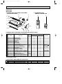
MSZ-A24NA
MSY-A24NA
8. INDOOR UNIT FUNCTIONAL PARTS AND
ELECTRICAL PARTS
1
9. ACCESSORY AND
REMOTE CONTROLLER
18
17
21
22
2
3
4
9
16
10
5
6
12
11
15
8
7
13
15
14
8. INDOOR UNIT FUNCTIONAL PARTS AND ELECTRICAL PARTS
Part numbers that are circled are not shown in the illustration.
No.
1
2
3
4
5
6
7
8
9
10
11
12
13
14
15
16
17
18
19
20
Part No.
E02
E02
E02
E02
E02
E02
E02
E02
E02
E02
E02
E02
E02
E02
E02
E02
E02
E02
E02
E02
E02
527
408
001
408
A58
685
685
527
A58
448
408
918
918
918
A58
A53
527
A58
918
528
529
302
509
504
702
235
040
041
034
300
303
303
333
329
468
452
452
308
375
307
034
034
Part Name
Symbol
in Wiring
Diagram
LINE FLOW FAN
BEARING MOUNT
SLEEVE BEARING
DRAIN HOSE
NOZZLE
VANE UPPER
VANE LOWER
VANE CRANK SET
MF
INDOOR FAN MOTOR ASSEMBLY W1
VANE MOTOR (VERTICAL)
MV2
VANE MOTOR (HORIZONTAL)
MV1
MOTOR BAND
DISPLAY P.C. BOARD
RECEIVER P.C. BOARD
ELECTRONIC CONTROL P.C. BOARD W2
ELECTRONIC CONTROL P.C. BOARD W2
RT11
ROOM TEMPERATURE THERMISTOR
TERMINAL BLOCK
TB
RT12, RT13
INDOOR COIL THERMISTOR
VANE MOTOR SUPPORT SET(RIGHT)
VANE MOTOR SUPPORT SET(LEFT)
Q'ty/unit
MSZ-A24NA
MSY-A24NA
1
1
1
1
1
1
1
1
1
2
1
1
1
1
1
1
1
1
1
1
1
1
1
1
2
1
1
1
1
1
1
1
1
1
1
1
1
1
1
1
Remarks
RC0J56 RIGHT & LEFT
UP & DOWN
AUTO RESTART
AUTO RESTART
W1 Including FAN MOTOR RUBBER MOUNT
W2 Including SW P.C. BOARD
9. ACCESSORY AND REMOTE CONTROLLER
E02 A58 426
E02 A53 426
22 E02 527 083
21
1
REMOTE CONTROLLER
REMOTE CONTROLLER
REMOTE CONTROLLER HOLDER
1
34
1
1
KM06B
KM06D
OB450-2.qxp
06.11.29 1:40 PM
Page 35
10. AIR CLEANING FILTER (ANTI-ALLERGY ENZYME FILTER)
● AIR CLEANING FILTER removes fine dust of 0.01 micron from air by means of static electricity.
● Normal life of AIR CLEANING FILTER is 1 year.
If AIR CLEANING FILTER is to be washed, soak AIR CLEANING FILTER in water (when showing dirt, in lukewarm water)
and rinse it delicately, without removing the filter from the frame about once every 3 months.
● Clogged AIR CLEANING FILTER may reduce the air conditioner capacity or cause frost on the air outlet.
● Do not remove or attach AIR CLEANING FILTER during unit operation.
Model
Part No.
MSZ-A24NA
MSY-A24NA
MAC-2300FT
Air cleaning filter
(Anti-allergy enzyme filter:blue bellows type)
35
OB450-2.qxp
06.11.29 1:40 PM
Page 36
10-2. RoHS PARTS LIST (RoHS compliant)
MSZ-A09NA MSY-A15NA
MSZ-A12NA MSY-A17NA
MSZ-A15NA
MSZ-A17NA
1. INDOOR UNIT STRUCTURAL PARTS
2. ACCESSORY AND REMOTE
CONTROLLER
9
1
12
11
10
8
2
7
(See 10-5.)
3
4
5
6
No.
RoHS
1. INDOOR UNIT STRUCTURAL PARTS
1
2
3
4
5
6
7
8
9
10
G
G
G
G
G
G
G
G
G
G
Part No.
E12
E12
E12
E12
E12
E12
A32
A49
913
915
915
916
234
000
067
010
100
100
E12 A32 975
E12 913 970
E12 A49 978
Q'ty/unit
Symbol
MSZMSYin Wiring
Part name
Remarks
Diagram A09NA A12NA A15NA A17NA A15NA A17NA
1
1
1
1
1
1
BOX
1 Including No.3,4
1
1
1
1
1
PANEL ASSEMBLY
2 2PCS/SET
2
2
2
2
2
SCREW CAP
1
1
1
1
1
1
FRONT PANEL
1
1
1
1
1
1
CATECHIN AIR FILTER (LEFT)
1
1
1
1
1
1
CATECHIN AIR FILTER (RIGHT)
1 MAC-415FT-E
1
1
1
1
1
AIR CLEANING FILTER
1
1
1
1
1
1
CORNER BOX (RIGHT)
1
1
1
1
1
1
INSTALLATION PLATE
1
1
1
1
1
1
CONDUIT PLATE
2. ACCESSORY AND REMOTE CONTROLLER
G E12 A54 426 REMOTE CONTROLLER
G E12 A49 426 REMOTE CONTROLLER
12 G E12 527 083 REMOTE CONTROLLER HOLDER
1
11
1
36
1
1
1
1
1
1
1
1
1
1
KM06A
KM06C
06.11.29 1:40 PM
MSZ-A09NA
Page 37
MSZ-A12NA
MSZ-A15NA
MSZ-A17NA
MSY-A15NA
MSY-A17NA
3. INDOOR UNIT ELECTRICAL PARTS AND FUNCTIONAL PARTS
17
18
1
15
16
14
2
3
4
5
6
11
10
9
12
No.
1
2
3
4
5
6
7
8
9
10
11
12
13
14
15
16
17
18
RoHS
OB450-2.qxp
G
G
G
G
G
G
G
G
G
G
G
G
G
G
G
G
G
G
G
G
G
G
G
G
G
Part No.
E12
E12
E12
E12
E12
E12
E12
E12
E12
E12
E12
E12
E12
E12
E12
E12
E12
E12
E12
E12
E12
E12
E12
E12
E12
751
001
897
A54
A56
897
913
915
A49
A49
A49
913
A54
A55
A56
A57
A51
A52
897
A54
A56
915
A54
897
897
509
504
702
235
235
303
040
095
979
780
779
375
452
452
452
452
452
452
308
307
307
782
300
333
302
8
7
12
13
Q'ty/unit
Symbol
in Wiring
Part name
MSZMSYDiagram A09NA A12NA A15NA A17NA A15NA A17NA
1
1
BEARING MOUNT
1
1
1
1
1
1
SLEEVE BEARING
1
1
1
1
1
1
DRAIN HOSE
1
1
1
1
NOZZLE ASSEMBLY
1
1
1
1
NOZZLE ASSEMBLY
1
1
MV
1
1
VANE MOTOR UNIT (HORIZONTAL)
1
1
1
1
1
1
HORIZONTAL VANE
1
1
1
1
1
1
POWER MONITOR RECEIVER P.C. BOARD HOLDER
1
1
1
1
1
1
CONDUIT COVER
1
1
1
1
1
1
TERMINAL BLOCK COVER
1
1
1
1
1
1
TERMINAL BLOCK HOLDER
1
1
1
1
TB
1
1
TERMINAL BLOCK
1
1
1
1
ELECTRONIC CONTROL P.C. BOARD W1
1
ELECTRONIC CONTROL P.C. BOARD W1
1
1
ELECTRONIC CONTROL P.C. BOARD W1
1
ELECTRONIC CONTROL P.C. BOARD W1
ELECTRONIC CONTROL P.C. BOARD W1
1
ELECTRONIC CONTROL P.C. BOARD W1
1
1
1
ROOM TEMPERATURE THERMISTOR RT11
1
1
1
1
RT12, RT13 1
INDOOR COIL THERMISTOR
1
RT12, RT13
1
1
INDOOR COIL THERMISTOR
1
1
1
1
SWITCH HOLDER
1
1
1
1
MF
1
1
INDOOR FAN MOTOR W2
1
1
1
1
1
1
MOTOR BAND
1
1
1
1
1
1
LINE FLOW FAN
1
1
1
1
W1 Including SW P.C. BOARD and POWER MONITOR RECEIVER P.C. BOARD
W2 Including FAN MOTOR RUBBER MOUNT (2 PCS/SET)
37
Remarks
UP & DOWN
AUTO RESTART
AUTO RESTART
AUTO RESTART
AUTO RESTART
AUTO RESTART
AUTO RESTART
RC0J30-
OB450-2.qxp
06.11.29 1:40 PM
MSZ-A09NA
Page 38
MSZ-A12NA
MSZ-A15NA
MSZ-A17NA
MSY-A15NA
MSY-A17NA
4. INDOOR UNIT HEAT EXCHANGER
1
2
No.
1
2
3
RoHS
3
G
G
G
G
G
Part No.
E12
E12
E12
E12
E12
A54
A56
815
155
151
620
620
666
666
667
Part name
INDOOR HEAT EXCHANGER
INDOOR HEAT EXCHANGER
UNION (GAS)
UNION (GAS)
UNION (LIQUID)
Q'ty/unit
Symbol
MSZMSYin Wiring
Remarks
Diagram A09NA A12NA A15NA A17NA A15NA A17NA
1
1
1
1
1
1
{3/8
1
1
1
1
1
1 {1/2
1
1
1
1
1
1 {1/4
5. AIR CLEANING FILTER (ANTI-ALLERGY ENZYME FILTER)
● AIR CLEANING FILTER removes fine dust of 0.01 micron from air by means of static electricity.
● Normal life of AIR CLEANING FILTER is 1 year.
If AIR CLEANING FILTER is to be washed, soak AIR CLEANING FILTER in water (when showing dirt, in lukewarm
water) and rinse it delicately, without removing the filter from the frame about once every 3 months.
● Clogged AIR CLEANING FILTER may reduce the air conditioner capacity or cause frost on the air outlet.
● Do not remove or attach AIR CLEANING FILTER during unit operation.
Model
MSZ-A09NA MSY-A15NA
MSZ-A12NA MSY-A17NA
MSZ-A15NA MSZ-A17NA
Part No.
MAC-415FT-E
Replacement of the air cleaning filter
(2) Remove the air cleaning filter(Blue
bellows type) from the catechin air filter.
(1) Remove the catechin air filter(left one)
The air cleaning filter is not attached
to the right side catechin air filter
Air cleaning filter
(Blue bellows type)
38
06.11.29 1:40 PM
Page 39
MSZ-A24NA
MSY-A24NA
6. INDOOR UNIT STRUCTURAL PARTS
7. INDOOR UNIT HEAT EXCHANGER
1
2
11
3
4
8
5
9
(See 10-10.)
12
13
6
7
6. INDOOR UNIT STRUCTURAL PARTS
Part number that is circled is not shown in the illustration.
No.
RoHS
OB450-2.qxp
G
G
G
G
G
G
G
G
G
10 G
1
2
3
4
5
6
7
8
9
Part No.
E12 527 970
E12 685 234
E12 888 000
E12 408 142
E12 685 067
E12 888 010
E12 534 100
E12 685 975
E12 888 007
Part Name
Symbol
in Wiring
Diagram
INSTALLATION PLATE
BOX
FRONT PANEL ASSEMBLY
CATCH
SCREW CAP
GRILLE
CATECHIN AIR FILTER
CORNER BOX (RIGHT)
AIR CLEANING FILTER
LAMP PANEL
Q'ty/unit
MSZ-A24NA
MSY-A24NA
1
1
1
4
3
1
2
1
2
1
1
1
1
4
3
1
2
1
2
1
1
1
1
1
1
1
Remarks
Including No.5,6
4PCS/ SET
3PCS/ SET
1PC/ SET
MAC-2300FT
7. INDOOR UNIT HEAT EXCHANGER
11 G E12 A58 620 INDOOR HEAT EXCHANGER
12 G E12 527 666 UNION (GAS)
13 G E12 151 667 UNION (LIQUID)
39
{5/8
{1/4
OB450-2.qxp
06.11.29 1:40 PM
Page 40
MSZ-A24NA
MSY-A24NA
8. INDOOR UNIT FUNCTIONAL PARTS AND
ELECTRICAL PARTS
1
9. ACCESSORY AND
REMOTE CONTROLLER
18
17
21
22
2
3
4
9
16
10
5
6
12
11
15
8
7
13
15
14
8. INDOOR UNIT FUNCTIONAL PARTS AND ELECTRICAL PARTS
No.
1
2
3
4
5
6
7
8
9
10
11
12
13
14
15
16
17
18
19
20
RoHS
Part numbers that are circled are not shown in the illustration.
G
G
G
G
G
G
G
G
G
G
G
G
G
G
G
G
G
G
G
G
G
Part No.
E12
E12
E12
E12
E12
E12
E12
E12
E12
E12
E12
E12
E12
E12
E12
E12
E12
E12
E12
E12
E12
527
408
001
408
A58
685
685
527
A58
448
408
918
918
918
A58
A53
527
A58
918
528
529
302
509
504
702
235
040
041
034
300
303
303
333
329
468
452
452
308
375
307
034
034
Part Name
Symbol
in Wiring
Diagram
LINE FLOW FAN
BEARING MOUNT
SLEEVE BEARING
DRAIN HOSE
NOZZLE
VANE UPPER
VANE LOWER
VANE CRANK SET
MF
INDOOR FAN MOTOR ASSEMBLY W1
VANE MOTOR (VERTICAL)
MV2
VANE MOTOR (HORIZONTAL)
MV1
MOTOR BAND
DISPLAY P.C. BOARD
RECEIVER P.C. BOARD
ELECTRONIC CONTROL P.C. BOARD W2
ELECTRONIC CONTROL P.C. BOARD W2
RT11
ROOM TEMPERATURE THERMISTOR
TERMINAL BLOCK
TB
RT12, RT13
INDOOR COIL THERMISTOR
VANE MOTOR SUPPORT SET(RIGHT)
VANE MOTOR SUPPORT SET(LEFT)
Q'ty/unit
MSZ-A24NA
MSY-A24NA
1
1
1
1
1
1
1
1
1
2
1
1
1
1
1
1
1
1
1
1
1
1
1
1
2
1
1
1
1
1
1
1
1
1
1
1
1
1
1
1
Remarks
RC0J56 RIGHT & LEFT
UP & DOWN
AUTO RESTART
AUTO RESTART
W1 Including FAN MOTOR RUBBER MOUNT
W2 Including SW P.C. BOARD
9. ACCESSORY AND REMOTE CONTROLLER
1
G E12 A58 426 REMOTE CONTROLLER
G E12 A53 426 REMOTE CONTROLLER
22 G E12 527 083 REMOTE CONTROLLER HOLDER
21
1
40
1
1
KM06B
KM06D
OB450-2.qxp
06.11.29 1:40 PM
Page 41
10. AIR CLEANING FILTER (ANTI-ALLERGY ENZYME FILTER)
● AIR CLEANING FILTER removes fine dust of 0.01 micron from air by means of static electricity.
● Normal life of AIR CLEANING FILTER is 1 year.
If AIR CLEANING FILTER is to be washed, soak AIR CLEANING FILTER in water (when showing dirt, in lukewarm water)
and rinse it delicately, without removing the filter from the frame about once every 3 months.
● Clogged AIR CLEANING FILTER may reduce the air conditioner capacity or cause frost on the air outlet.
● Do not remove or attach AIR CLEANING FILTER during unit operation.
Model
Part No.
MSZ-A24NA
MSY-A24NA
MAC-2300FT
Air cleaning filter
(Anti-allergy enzyme filter:blue bellows type)
41
OB450-2.qxp
11
06.11.29 1:40 PM
Page 42
MICROPROCESSOR CONTROL
MSZ-A09NA
MSZ-A12NA
MSZ-A15NA
MSZ-A17NA MSY-A15NA
MSZ-A24NA MSY-A17NA
MSY-A24NA
WIRELESS REMOTE CONTROLLER
w These pictures show MSZ-A24.
Signal transmitting section
(This diagram shows an overall view.)
Operation display section
ON/OFF (operate/
stop) button
VANE button
(Horizontal vane button)
Fan speed control button
Temperature buttons
Off-timer button
Operation select button
Indication of
remote controller
model is on back
ECONO COOL button
On-timer button
WIDE VANE button
(Vertical vane button)
(MSZ-A24, MSY-A24)
TIME set buttons
Forward button
Backward button
POWERFUL button
CLOCK set button
RESET button
NOTE
Use the remote controller
provided with the unit only.
Do not use other remote
controller.
overall view.)
view.)
(This diagram shows an overall
Once the operation mode is set, the same operation mode can be repeated by simply turning OPERATE/STOP
(ON/OFF) button ON.
Indoor unit receives the signal with a beep tone.
When the system turns off, 3-minute time delay will operate to protect system from overload and compressor will not
restart for 3 minutes.
INDOOR UNIT DISPLAY SECTION
Operation Indicator lamp
The operation indicator at the right side of the indoor unit indicates the operation state.
•The following indication applies regardless of shape of the indicator.
Indication
Difference
between target
temperature
and room
temperature
Operation state
This shows that the air conditioner is operating
to reach the target temperature.
Please wait until the target temperature is
obtained.
This shows that the room temperature is
approaching the target temperature.
This shows a state of standby for operation.
(For multi system air conditioner)
42
Approx.
4°F
or more
Operation Indicator
Lighted
Blinking
Not lighted
Approx.
4°F
or less
—
OB450-2.qxp
06.11.29 1:40 PM
11-1. COOL (
Page 43
) OPERATION
(1) Press OPERATE/STOP(ON/OFF) button.
OPERATION INDICATOR lamp of the indoor unit turns on with a beep tone.
(2) Select COOL mode with OPERATION SELECT button.
(3) Press TEMPERATURE buttons (TOO WARM or TOO COOL button)to select the desired temperature.
The setting range is 61 ~ 88°F.
1. Coil frost prevention
When the temperature of indoor heat exchanger becomes too low, the coil frost prevention mode works.
The indoor fan operates at the set speed and the compressor stops. This mode continues until the temperature of indoor
heat exchanger rises.
2. Low outside temperature operation
When the outside temperature lowers during cool mode operation, low outside temperature operation starts, and the
outdoor fan slows or stops.
11-2. DRY (
) OPERATION
(1) Press OPERATE/STOP(ON/OFF) button.
OPERATION INDICATOR lamp of the indoor unit turns on with a beep tone.
(2) Select DRY mode with OPERATION SELECT button.
(3) The set temperature is determined from the initial room temperature.
1. Coil frost prevention
Coil frost prevention is as same as COOL mode. (11-1.1.)
2. Low outside temperature operation
Low outside temperature operation is as same as COOL mode. (11-1.2.)
11-3. HEAT (
) OPERATION (MSZ)
(1) Press OPERATE/STOP(ON/OFF) button.
OPERATION INDICATOR lamp of the indoor unit turns on with a beep tone.
(2) Select HEAT mode with OPERATION SELECT button.
(3) Press TEMPERATURE buttons (TOO WARM or TOO COOL button) to select the desired temperature.
The setting range is 61 ~ 88°F.
1. Cold air prevention control
When the compressor is not operating or is starting, and the temperature of indoor heat exchanger and/or the room
temperature is low or when defrosting is being done, the indoor fan will stop or rotate in Very Low speed.
2. High pressure protection
In HEAT operation the compressor operational frequency is controlled by the temperature of the indoor heat exchanger to
prevent the condensing pressure from increasing excessively.
3. Defrosting
Defrosting starts when the temperature of outdoor heat exchanger becomes too low.
The indoor/outdoor fans stop, the 4-way valve reverses, and the compressor starts.
This mode continues until the temperature of outdoor heat exchanger rises or the fixed time passes.
11-4. FAN( d )OPERATION (MSY)
(1) Press OPERATE/STOP(ON/OFF) button.
OPERATION INDICATOR lamp of the indoor unit turns ON with a beep tone.
(2) Select FAN mode with OPERATION SELECT button.
(3) Select the desired fan speed. When AUTO, it becomes Low.
Only indoor fan operates. Outdoor unit does not operate.
11-5. “I FEEL CONTROL” (
) OPERATION (MSY)
(1) Press OPERATE/STOP (ON/OFF) button on the remote
controller. OPERATION INDICATOR lamp of the indoor
Initial room temperature
unit turns on with a beep tone.
75°F or more
(2) Select “I FEEL CONTROL” mode with OPERATION
SELECT button.
(3) The operation mode is determined by the room temperaless than 75°F
ture at start-up of the operation.
• Once the mode is fixed, the mode does not change by room temperature afterwards.
•
Under the ON-TIMER (
operation starts.
Mode
COOL mode of
"I FEEL CONTROL"
DRY mode of
"I FEEL CONTROL"
) operation, mode is determined according to the room temperature at the set time the
43
OB450-2.qxp
06.11.29 1:40 PM
Page 44
(4) The initial set temperature is decided by the initial room temperature.
Model
Initial room temperature
COOL mode of
"I FEEL CONTROL"
79°F or more
Initial set temperature
75°F
❈1
Initial room temperature
77°F to 79°F
DRY mode of
"I FEEL CONTROL"
minus 4°F
Initial room temperature
less than 77°F
minus 4°F
❈1 When the system is restarted with the remote controller, the system operates with the previous set temperature regardless of room temperature at restart.
The set temperature is calculated by the previous set temperature.
(5) TEMPERATURE buttons
In “I FEEL CONTROL” (
) mode, set temperature is decided by the microprocessor based on the room temperature.
In addition, set temperature can be controlled by TOO WARM or TOO COOL buttons when you feel too cool or too warm.
Each time the TOO WARM or TOO COOL button is pressed, the indoor unit receives the signal and emits a beep tone.
• Fuzzy control
When the TOO COOL or TOO WARM button is pressed, the microprocessor changes the set temperature, considering
the room temperature, the frequency of pressing TOO COOL or TOO WARM button and the user’s preference to heat or
cool. So this is called “Fuzzy control”, and works only in “I FEEL CONTROL” mode.
In DRY mode of “I FEEL CONTROL”, the set temperature doesn’t change.
TOO
COOL
…To raise the set temperature 2~4 degrees (°F)
TOO
WARM
…To lower the set temperature 2~4 degrees (°F)
11-6. AUTO CHANGE OVER ··· AUTO MODE OPERATION (MSZ)
Once desired temperature is set, unit operation is switched automatically between COOL and HEAT operation.
Mode selection
(1) Initial mode
When unit starts the operation with AUTO operation from off;
• If the room temperature is higher than the set temperature, operation starts in COOL mode.
• If the room temperature is equal to or lower than the set temperature, operation starts in HEAT mode.
(2) Mode change
COOL mode changes to HEAT mode when about 15 minutes have passed with the room temperature 4 degrees
below the set temperature.
HEAT mode changes to COOL mode when about 15 minutes have passed with the room temperature 4 degrees
above the set temperature.
NOTE:
If two or more indoor units are operating in multi system, there might be a case that the indoor unit, which is operating
in
(AUTO), cannot change over to the other operating mode (COOL
HEAT) and becomes a state of standby.
Refer to 8-1. ”INFORMATION FOR MULTI SYSTEM AIR CONDITIONER”.
44
OB450-2.qxp
06.11.29 1:40 PM
Page 45
11-7. AUTO VANE OPERATION
1. Horizontal vane
(1) Vane motor drive
These models are equipped with a stepping motor for the horizontal vane. The rotating direction, speed, and angle of
the motor are controlled by pulse signals (approximate 12V) transmitted from indoor microprocessor.
(2) The horizontal vane angle and mode change as follows by pressing VANE CONTROL button.
MSZ-A09/12/15/17
MSY-A15/17
MSZ-A24
MSY-A24
(3) Positioning
The vane is once pressed to the vane stopper to confirm the standard position and then set to the desired angle.
Confirming of standard position is performed in the following cases.
(a) When the operation starts or finishes (including timer operation).
(b) When the test run starts.
(c) When multi-standby starts or finishes.
(4) VANE AUTO (
) mode
In VANE AUTO mode, the microprocessor automatically determines the vane angle and operation to make the optimum
room-temperature distribution.
(1) In COOL and DRY operation
Vane angle is fixed to Horizontal position or Angle 1.
Upward
Vane angle is fixed to Angle 4.
(2) In HEAT operation (MSZ)
(5) STOP (operation OFF) and ON-TIMER standby
In the following cases, the horizontal vane returns to the closed position.
(a) When OPERATE/STOP (ON/OFF) button is pressed (POWER OFF).
(b) When the operation is stopped by the emergency operation.
(c) When ON-TIMER is ON standby.
(6) Dew prevention
During COOL or DRY operation with the vane angle at Angle 2 ~ 4 (A09 ~ 17) / Angle 3 ~ 5 (A24) when the compressor
cumulative operation time exceeds 1 hour, the vane angle automatically changes to Angle 1 for dew prevention.
(7) SWING MODE ( )
By selecting SWING mode with VANE CONTROL button, the horizontal vane swings vertically. The remote controller
displays “
”.
(8) Cold air prevention in HEAT operation (MSZ)
The horizontal vane position is set to Upward.
NOTE: When 2 or more indoor units are operated with multi outdoor unit, even if any indoor unit turns thermostat off,
this control doesn’t work in the indoor unit.
45
OB450-2.qxp
06.11.29 1:40 PM
Page 46
(9) To change the air flow direction not to blow directly onto your body. (MSZ-A09/12/15/17, MSY-A15/17)
To change the air
flow direction
Pressing and holding
VANE CONTROL
button for 2 seconds
or more causes
the horizontal vane
to reverse and
move to horizontal
position.
When to use this function?
COOL/DRY
HEAT
(for MSZ)
Use this function if you don’t
want the air from the indoor
unit to blow directly onto your
body.
• Depending on the shape of
the room,the air may blow
directly onto your body.
The air conditioner starts the
cooling or drying operation
approx. 3 minutes after the
vane has moved to the horizontal position.
• When VANE CONTROL
button is pressed again,
the vane returns to the
previously-set position
and the air conditioner
starts the cooling or
drying operation in
approx. 3 minutes.
The air conditioner starts heating operation approx. 3 minutes
after the vane has moved to the
horizontal position.
• Sometimes the area
around your feet may not
warm. To warn the area
around the feet, set the
horizontal vane to
(AUTO) or the downwardblowing position.
• Press VANE CONTROL
button again to return the
vane to the previously-set
position.
Horizontal
position
• When VANE CONTROL
button is pressed again,
the vane returns to the
previously-set position
and the air conditioner
starts the heating operation
in approx. 3 minutes.
NOTE:
• If you make the air flow not to blow directly onto your body by pressing VANE CONTROL button,
the compressor stops for 3 minutes even during the operation of the air conditioner.
• The air conditioner operates with Very Low speed until the compressor turns on again.
(10) ECONO COOL (
) operation (ECONOmical operation)
When ECONO COOL button is pressed in COOL mode, set temperature is automatically set 3.6°F higher than that in
COOL mode.
Also the horizontal vane swings in various cycle.
SWING operation makes you feel cooler than set temperature. So, even though the set temperature is higher than that
in COOL mode, the air conditioner can keep comfort. As a result, energy can be saved.
ECONO COOL operation is cancelled when ECONO COOL button is pressed once again or VANE CONTROL
button is pressed or change to other operation mode.
) operation
(11) POWERFUL (
The air conditioner automatically adjusts the fan speed and the set temperature, and operates the POWERFUL
mode.The POWERFUL mode is automatically released 15 minutes after operation starts, and the operation mode
returns to the mode prior to POWERFUL operation.
2. Vertical vane (MSZ-A24, MSY-A24)
(1) Vane motor drive
These models are equipped with a stepping motor for the vertical vane. The rotating direction, speed, and angle of the
motor are controlled by pulse signals (approximate 12V) transmitted from microprocessor.
(2) The vertical vane angle and mode change as follows by pressing WIDE VANE button.
1
2
3
4
SWING
5
6
(3) Positioning
The vane is once pressed to the vane stopper to confirm the standard position and then set to the desired angle.
Confirming of standard position is performed in the following cases.
(a) When OPERATE/STOP(ON/OFF) button is pressed (POWER ON/OFF).
(b) When SWING is started or finished.
(c) When the power supply turns ON.
(4) SWING MODE ( )
By selecting SWING mode with WIDE VANE button, the vertical vane swings horizontally.
The remote controller displays “
”.
46
OB450-2.qxp
06.11.29 1:40 PM
Page 47
(5) WIDE MODE (
)
By selecting WIDE mode with WIDE VANE button, indoor fan speed becomes faster than setting fan speed on the
remote controller (W). The remote controller displays “
”.
NOTE : The position of vane angle 3, angle 4 and angle 5 are different in COOL operation and HEAT operation.
W Indoor fan speed becomes faster than setting fan speed on the remote controller even when
selected.
or
is
11-8. TIMER OPERATION
1. How to set the time
(1) Press OPERATE/STOP (ON/OFF) button to start the air conditioner.
(2) Check that the current time is set correctly.
NOTE : Timer operation will not work without setting the current time. Initially “AM0:00” blinks at the current time display of
TIME MONITOR, so set the current time correctly with CLOCK SET button.
How to set the current time
(1)Press the CLOCK set button.
(2)Press the TIME SET buttons (
and
) to set the current time.
• Each time FORWARD button (
) is press, the set time increases by 1minute, and each time BACKWARD button
(
) is press, the set time decreases by 1minute.
• Pressing thoes buttons longer increases / decreases the set time by 10 minutes.
Press the CLOCK set button.
ON timer setting
(1) Press ON-TIMER button(
START
) during operation.
(2) Set the time of the timer using TIME SET buttons (
OFF timer setting
(1) Press OFF-TIMER button (
STOP
and
) during operation.
(2) Set the time of the timer using TIME SET buttons (
w Each time FORWARD button (
(
).w
and
). w
) is pressed, the set time increases by 10 minutes; each time BACKWARD button
) is pressed, the set time decreases by 10 minutes.
2. Cancel
START
To cancel ON timer, press ON-TIMER button (
).
To cancel OFF timer, press OFF-TIMER button( STOP ).
TIMER is cancelled and the display of set time disappears.
PROGRAM TIMER
• OFF timer and ON timer can be used in combination. The timer of the set time that is reached first will operate first.
• “ ” and “ ” display shows the order of OFF timer and ON timer operation.
(Example 1) The current time is 8:00 PM.
(Example 2) The current time is 11:00 AM.
The unit turns off at 11:00 PM, and on at 6:00 AM.
The unit turns on at 5:00 PM, and off at 9:00 PM.
NOTE : If the main power is turned off or a power failure occurs while AUTO START/STOP timer is active, the timer setting
is cancelled. As these models are equipped with an auto restart function, the air conditioner starts operating with
timer cancelled when power is restored.
47
OB450-2.qxp
06.11.29 1:40 PM
Page 48
11-9. EMERGENCY/TEST OPERATION
In case of test run operation or emergency operation, use EMERGENCY OPERATION switch on the front of the indoor
unit. Emergency operation is available when the remote controller is missing, has failed or the batteries of the remote
controller run down. The unit will start and OPERATION INDICATOR lamp will light.
The first 30 minutes of operation is the test run operation. This operation is for servicing. The Indoor fan speed runs at
High speed and the system is in continuous operation (with thermostat ON).
After 30 minutes of test run operation the system shifts to EMERGENCY COOL / HEAT MODE with a set temperature of
75°F. The fan speed shifts to Med..
All protective operations such as the coil frost prevention works even in emergency operation.
In the test run or emergency operation, the horizontal vane operates in VANE AUTO (
) mode.
Emergency operation continues until EMERGENCY OPERATION switch is pressed once or twice or the unit receives any
signal from the remote controller. In case of latter normal operation will start.
NOTE : Do not press EMERGENCY OPERATION switch during normal operation.
Operation mode
Set temperature
Fan speed
E.O.
SW
EMERGENCY OPERATION switch
Horizontal vane
75°F
HEAT
(MSZ)
75°F
Medium
Medium
Auto
Auto
COOL
The operation mode is indicated by the Operation
Indicator lamp on the indoor unit as following
Operation indicator lamp
(MSZ type)
Press once <Cool>
Lighted
Press again <Heat>
Not lighted
Press once again <Stop>
(MSY type)
Press once <Cool>
Press again <Stop>
HEAD OFFICE: TOKYO BLDG., 2-7-3, MARUNOUCHI, CHIYODA-KU, TOKYO 100-8310, JAPAN
C Copyright 2006 MITSUBISHI ELECTRIC ENGINEERING CO.,LTD
Distributed in Dec. 2006. No. OB450 REVISED EDITION-A 7
Distributed in Apr. 2006. No. OB450 7
Made in Japan
New publication, effective Dec. 2006
Specifications subject to change without notice.