1
SG79Y513H02
SPLIT-TYPE AIR CONDITIONERS
Models
INSTALLATION MANUAL
MSZ-GA50 VA
MSZ-GA60 VA
MSZ-GA71 VA Series
MSZ-GA80 VA
R410A
•
•
CAUTION
Be sure to read “THE FOLLOWING SHOULD ALWAYS BE OBSERVED FOR
SAFETY” before installing the air conditioner.
Be sure to observe the cautions specified here as they include important items
related to safety.
The indications and meanings are as follows.
■ Do not install the unit in a place where an inflammable gas leaks.
If gas leak and accumulate in the area surrounding the unit, it could cause an
explosion.
■ Install an earth leakage breaker depending on the installation place
(Where it is humid).
If an earth leakage breaker is not installed, it could cause an electric shock.
WARNING
■ Perform the drainage/piping work securely according to the installation
manual.
If there is a defect in the drainage/piping work, water could drop from the unit
and household goods could be wet and damaged.
CAUTION
Could lead to serious injury in particular environments when operated incorrectly.
■ Fasten a flare nut with a torque wrench as specified in this manual.
When fastened too tight, a flare nut may broken after a long period and cause
a leakage of refrigerant.
After reading this manual, be sure to keep it together with the OPERATING
INSTRUCTIONS in a handy place on the customer’s site.
WARNING
■ Do not install the unit by yourself (customer).
Incomplete installation could cause injury due to fire, electric shock, the unit
falling or leakage of water. Consult the dealer from whom you purchased the
unit or special installer.
■ Install the unit securely in a place which can bear the weight of the unit.
When installed in an insufficient strong place, the unit could fall causing injury.
■ Use the specified wires to connect the indoor and outdoor units securely
and attach the wires firmly to the terminal block connecting sections so
the stress of the wires is not applied to the sections.
Incomplete connecting and fixing could cause fire.
■ Do not use intermediate connection of the power cord or the extension
cord and do not connect many devices to one AC outlet.
It could cause a fire or an electric shock due to defective contact, defective
insulation, exceeding the permissible current, etc.
■ Check that the refrigerant gas do not leak after installation has completed.
If refrigerant gas leaks indoors, and comes into contact with the fire of a fan
heater, space heater, stove, etc., harmful substances will be generated.
■ Perform the installation securely referring to the installation manual.
Incomplete installation could cause a personal injury due to fire, electric
shock, the unit falling or leakage of water.
■ Perform electrical work according to the installation manual and be sure
to use an exclusive circuit.
If the capacity of the power circuit is insufficient or there is incomplete
electrical work, it could result in a fire or an electric shock.
■ Attach the electrical cover to the indoor unit and the service panel to the
outdoor unit securely.
If the electrical cover in the indoor unit and/or the service panel in the outdoor
unit are not attached securely, it could result in a fire or an electric shock due
to dust, water, etc.
■ Be sure to use the part provided or specified parts for the installation
work.
The use of defective parts could cause an injury or leakage of water due to a
fire, an electric shock, the unit falling, etc.
2. SELECTING THE INSTALLATION LOCATION
2-1 INDOOR UNIT
•
•
•
•
•
•
•
•
•
•
•
•
•
•
•
•
•
•
•
Where it is not exposed to strong wind.
Where airflow is good and dustless.
Where it is not exposed to rain and direct sunshine.
Where neighbours are not annoyed by operation sound or hot air.
Where rigid wall or support is available to prevent the increase of operation sound
or vibration.
Where there is no risk of combustible gas leakage.
When installing the unit at a high level, be sure to fix the unit legs.
Where it is at least 3 m away from the antenna of TV set or radio. Operation of the
air conditioner interferes with radio or TV reception in areas where reception is
weak. An amplifier may be required for the affected device.
Install the unit horizontally.
Please install it in an area not affected by snowfall or blowing snow. In areas with
heavy snow, please install a canopy, a pedestal and/or some baffle boards.
Note:
It is advisable to make a piping loop near outdoor unit so as to reduce vibration
transmitted from there.
CAUTION
Avoid the following places for installation where air conditioner trouble is liable to occur.
Where flammable gas could leak.
Where there is much machine oil.
Salty places such as the seaside.
Where sulfide gas is generated such as a hot spring.
Where there is high-frequency or wireless equipment.
•
•
•
•
•
■ The appliance shall be installed in accordance with national wiring
regulations.
1
Where airflow is not blocked.
Where cool air spreads over the entire room.
Maximum refrigerant piping length between indoor unit and outdoor unit is 30 m
and the difference of height of both units is 15 m.
Rigid wall without vibration.
Where it is not exposed to direct sunshine.
Where easily drained.
At a distance 1 m or more away from your TV and radio. Operation of the air
conditioner interferes with radio or TV reception in areas where reception is weak.
An amplifier may be required for the affected device.
In a place as far away as possible from fluorescent and incandescent lights
(so the infrared remote control can operate the air conditioner normally).
Where the air filter can be removed and replaced easily.
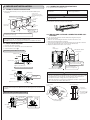
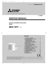
2-2 OUTDOOR UNIT
■ Be sure to cut off the main power in case of setting up the indoor
electronic control P.C. board or wiring works.
It could cause an electric shock.
■ When installing or relocating the unit, make sure that no substance
other than the specified refrigerant (R410A) enters the refrigerant circuit.
Any presence of foreign substance such as air can cause abnormal pressure
rise or an explosion.
IMPORTANT NOTES
TO COMPLY WITH THE REQUIREMENT OF
AUSTRALIAN STANDARD AS/NZS 3000
ELECTRICAL INSTALLATIONS (WIRING RULES)
THE ELECTRICAL WIRING REQUIRED BETWEEN
THE INDOOR AND OUTDOOR UNITS MUST BE
INSTALLED BY A LICENCED ELECTRICAL
CONTRACTOR.
■ Earth the unit.
Do not connect the earth to a gas pipe, water pipe, lightning rod or telephone
earth. Defective earthing could cause an electric shock.
Could lead to death, serious injury, etc.
•
When installing an MXZ
series outdoor unit, refer to
the MSZ type manual for
indoor unit set up.
[FLARE CONNECTION TYPE]
1. THE FOLLOWING SHOULD ALWAYS BE
OBSERVED FOR SAFETY
•
HFC
utilized
2-3 WIRELESS REMOTE CONTROLLER MOUNTING
•
•
Place of mounting
• Where it is easy to operate and easily visible.
• Where children can not touch.
Mounting
Select a position about 1.2 m above the floor, check that signals from the remote
controller are surely received by the indoor unit from that position (‘beep’ or ‘beepbeep’ receiving tone sounds). After that, attach remote controller holder
to a
pillar or wall and set the wireless remote controller .
In rooms where inverter type fluorescent lamps are used, the signal from the
wireless remote controller may not be received.
PIPING PREPARATION
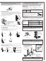
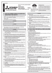
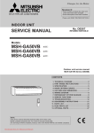
3. INSTALLATION DIAGRAM & ACCESSORIES
1 Specifications
Use the refrigerant pipes that meet the following specifications.
FLARED CONNECTIONS
•
•
•
•
Limits
Pipe
For liquid
MSZ-GA50/60/71/80
Pipe length
30 m max.
Height difference
15 m max.
No. of bends
•
Outside diameter Insulation thickness
This unit has flared connections on both indoor and outdoor sides.
Remove the outdoor units valve cover, then connect the pipe.
Refrigerant pipes are used to connect the indoor and outdoor units.
Be careful not to crush or bend the pipe in pipe bending.
For gas
GA50/GA60
6.35
8
GA71/GA80
9.52
8
GA50
12.7
8
GA60/GA71/GA80
15.88
8
No additional charge is required.
Exceeding 7 m
Be sure to use the insulation of specified thickness. Excessive thickness may cause
incorrect installation of the indoor unit and lack of thickness may cause dew drippage.
(Refer to the table below.)
MSZ-GA50
20 g/m × (refrigerant piping length (m) -7)
Refrigerant to
MSZ-GA60
20 g/m × (refrigerant piping length (m) -7)
be added
MSZ-GA71
55 g/m × (refrigerant piping length (m) -7)
MSZ-GA80
55 g/m × (refrigerant piping length (m) -7)
72 mm or more
100 mm or more for left and left
back piping (using spacer)
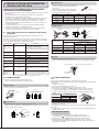
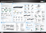
ACCESSORIES
Check the following parts before installation.
<Indoor unit>
Installation plate
1
Installation plate fixing screw 4 × 25 mm
Remote controller holder
Fixing screw for
3.5 × 16 mm (Black)
Battery (AAA) for remote controller
Wireless remote controller
Felt tape (Used for left or left-rear piping)
7
1
2
2
1
1
Anti-allergy enzyme filter
2
PART TO BE PROVIDED AT YOUR SITE
Decide the installation position using mark on the installation
plate indicating the indoor unit size as reference.
Be careful the
drain hose is not
raised.
120
or m mm
ore
1
200
or m mm
ore
2
8
H
Optional extension pipe
Indoor/outdoor unit connecting wire
(4-core 1.0 mm2-2.0 mm2)
1
Wall hole cover
1
Pipe fixing band (The quantity depends
on the pipe length.)
2 to 5
Fixing screw for
4 × 20 mm (The
quantity depends on the pipe length.)
2 to 5
1
Drain hose (or soft PVC. hose, 15 mm
inner dia. or hard PVC pipe VP16)
1
Refrigeration oil
1
Power supply cord (See the table in 5
INDOOR/OUTDOOR WIRE CONNECTION
AND OUTDOOR POWER SUPPLY CORD
CONNECTION for the cord size.)
1
Lock the catch.
B
360 mm
3
E
F
Separate the 2 connecting pipes and
apply insulation individually.
4
5
8 mm thickness thermal insulation
plastic
100
mm
K
ore
or m
ore
m
0m
10
15 mm
10.5 mm
Note: Do not
obstruct the
air outlet.
Left-rear
6
A
4-10 mm × 21 mm slot
Note:
When operating the air conditioner in low outside temperature,
be sure to follow the instructions described below.
Never install the outdoor unit in a place where its air inlet/outlet
side may be exposed directly to wind.
To prevent exposure to wind, install the outdoor unit with its
air inlet side facing the wall.
To prevent exposure to wind, it is recommended to install a
baffle board on the air outlet side of the outdoor unit.
•
•
•
C
Left
Downward
500 mm or more
Putty
17 mm
1
330 mm
8
7
1800 mm or
more from
the floor
G
Piping tape
500 mm
Piping can be directed towards rear,
right, downward, left or left-rear
directions.
Front
Rear side
Right
Rear
7 mm or more
1
Wall hole sleeve
100 mm
D
1
Extension pipe
Air outlet
Heat resisting
foam plastic
0.045 specific
gravity
CAUTION
Additional charge is required.
840 mm
Insulation material
Use a copper pipe or a copper-alloy seamless pipe with a thickness of 0.8 mm
(for ø6.35, 9.52) or 1.0 mm (for ø12.7, ø15.88). Never use any pipe with a thickness
less than 0.8 mm (for ø6.35, 9.52) or 1.0 mm (for ø12.7, ø15.88), as the pressure
resistance is insufficient.
2 Ensure that the 2 refrigerant pipes are insulated to prevent condensation.
3 Refrigerant pipe bending radius must be 100 mm or more.
Refrigerant adjustment ... If pipe length exceeds 7 m, additional refrigerant
(R-410A) charge is required.
(The outdoor unit is charged with refrigerant for pipe length up to 7 m.)
Up to 7 m
mm
•
10 max.
Pipe length
mm
or m
When the piping is to be attached to a
wall containing metals (tin plated) or
metal netting, use a chemically treated
wooden piece 20 mm or thicker
between the wall and the piping or
wrap 7 to 8 turns of insulation vinyl
tape around the piping.
ore
50
m
0m
or m
350
mm
or m
ore
Units should be installed by licensed contractor according
to local code requirement.
4-3 CONNECTING WIRE SPECIFICATIONS
4. INDOOR UNIT INSTALLATION
•
4-1 FIXING OF INSTALLATION PLATE
•
Find a structural material (such as a stud) in the wall and fix installation plate
horizontally.
72 mm or more
100 mm or more for left
and left back piping (using
spacer)
Bind the line to the center hole.
ore
m or m
200 m
ll)
a
w
e
(off th
ore
m or m
120 m
wall)
e
th
ff
(o
Use special room air conditioning circuit.
Cable 4-core 1.0 mm2, in conformity
with Design 245 IEC 57.
Indoor/outdoor unit connecting wire
Specification
WARNING
Never cut the indoor and outdoor unit connecting wire and connect it to other wires.
It may cause a fire.
Do not bundle the spare wire, but put it as shown below.
ore
m or m
1800 m floor
e
from th
Installation
plate fixing
screw
4 × 25 mm
Installation
plate
Plumb
Align the plumb line
with the mark .
4-4 INDOOR AND OUTDOOR CONNECTING WIRE CONNECTION
To prevent the installation plate from vibrating, be sure to fix the holes
as indicated by the arrows {.
When bolts recessed in the concrete wall are to be utilized, secure the installation
plate
using 11 × 20 · 11 × 26 oval hole (450 mm pitch).
If the recessed bolt is too long, change it for a shorter one available in the market.
4-2 WALL HOLE DRILLING
1 Determine the wall hole position.
2 Drill a 75 mm hole so that outside can be lower than inside.
3 Insert the wall hole sleeve .
You can connect indoor/outdoor lead wire without removing the front panel.
1 Open the front panel.
2 Remove one screw holding the electrical cover, then remove the cover.
3 Remove the VA clamp and the cord clamp.
4 Pass the indoor/outdoor unit connecting wire from the back of the indoor unit and
process the end of the wire, then connect it to the terminal block.
5 Replace the fixture and electrical cover securely.
Indoor
terminal block
ELECTRICAL COVER
VA clamp
Positioning of the holes on the wall
Fixing screws
Installation plate
100 mm
Insert the scale.
Align the scale with the line.
Never fail to hook the left claw on
the wire fixture to secure indoor/
outdoor unit connecting wire .
Hole of dia.
75 mm
Securely push the wire into
the terminal block until no
part of its core is appeared.
Repeat the same procedure for the left hole.
Indoor/outdoor unit connecting wire
Wall hole
WARNING
Wall thickness
75 mm dia.
•
One scale
Cut with 1 extra
scale length.
•
(Indoor side)
Use the indoor/outdoor unit connecting wire that meets the Standards to connect
the indoor and outdoor units and fix the wire to the terminal block securely so that
no external force is conveyed to the connecting section of the terminal block.
Incomplete connection or fixing of the wire could result in a fire.
Attach the electrical cover securely. If it is attached incorrectly, it could result in a
fire or an electric shock due to dust, water, etc.
(Wall hole cross section)
Wall hole sleeve
Be sure to use wall hole sleeve
to prevent the outdoor connecting wires from
contacting with metal part in the wall and to prevent damage by rat in case the wall
is hollow.
Seal the wall hole
gap with putty .
Earth wire
(green/yellow)
Indoor/outdoor unit
connecting wire
4-core 1.0 mm2
Terminal
block
Cut off the
extra length.
Lead wire
Pipe fixing
band
Fix the pipe to wall with
pipe fixing band .
<Connection details>
Indoor unit
Wall hole
sleeve
Indoor terminal block
15 mm
35 mm
Wall hole sealing and fixing pipe to wall
Wall hole cover
Loosen terminal
screw.
Fixing screw
Outdoor terminal block
FOR LEFT OR LEFT-REAR PIPING
CAUTION
•
•
•
•
•
Be careful not to make mis-wiring.
Firmly tighten the terminal screws to prevent them from loosening.
After tightening, pull the wires lightly to confirm that they do not move.
If the connecting wire is incorrectly connected to the terminal block, the unit does
not operate normally.
If an earth is incorrect, it may cause an electric shock.
•
Pipe arrangement
Put the refrigerant piping and the drain hose together, then apply felt tape
Be careful drain
hose is not heaved.
to them.
Cut off in case of left piping.
4-5 AUTO RESTART FUNCTION
•
•
These models are equipped with an auto restart function. If you do not want to use this
function, please consult the service representative because the setting of the unit needs
to be changed.
When the indoor unit is controlled with the remote controller, the operation mode, the
set temperature, and the fan speed are memorized by the indoor electronic control P.C.
board. The auto restart function sets to work the moment the power has restored after
power failure, then the unit will restart automatically. If the unit is operated in “AUTO”
mode before power failure, the operation mode (COOL, DRY or HEAT) is not stored in
the memory. When the main power is turned on, the unit decides the operation mode
by the initial room temperature at restart and starts operation again.
Operation
Use a bandage stopper at
the end of felt tape .
Felt tape
Firmly apply felt tape
from the end.
overlap width should be 1/3
(Felt tape
the tape width.)
REATTACHING DRAIN HOSE
Be sure to reattach the drain hose and the drain cap in case of left or left-rear piping.
Otherwise, it could cause drops of water to drip down from the drain hose.
1 If the main power (230V AC) has been cut, the operation settings remain.
2 When three minutes have passed after power was restored, the unit will restart
automatically according to the memory.
Notes:
The operation settings are memorized when 10 seconds have passed after the
remote controller was operated.
If the main power is turned off or a power failure occurs while AUTO START/STOP
timer is active, the timer setting is cancelled. As these models are equipped with the
auto restart function, the air conditioner should start operating at the same time that
a power has restored.
If the unit has been off with the remote controller before power failure, the auto
restart function does not work as the power button of the remote controller is off.
To prevent breaker off due to the rush of starting current, systematize other home
appliances not to turn on at the same time.
•
•
Drain cap
•
•
4-6 PIPE FORMING
•
•
•
•
•
Place the drain hose below the refrigerant piping.
Make sure that the drain hose is not heaved or snaked.
Do not pull the hose to apply the tape.
When the drain hose passes the room, be sure to wrap insulation material (obtainable at a store) around it.
Wrap the felt tape
around the pipe and the drain hose, then put the pipe in the
back space of the indoor unit.
1 Pull out the drain cap at the rear right of the indoor unit.
Hold the convex section at the end and pull the drain cap.
Drain cap
Liquid pipe
Gas pipe
Drain hose
2 Pull out the drain hose at the rear left of the indoor unit.
Hold the claw marked by the arrow and pull out the drain hose forward.
Indoor/outdoor unit
connecting wire
Felt tape
FOR REAR, RIGHT OR DOWNWARD PIPING
•
Pipe arrangement
Put the refrigerant piping and the drain hose together, then apply piping tape
them.
Be careful drain hose is not
heaved.
to
Firmly apply piping tape
from the end.
Drain hose
3 Put the drain cap into the section to which the drain hose is to be
attached at the rear of the indoor unit.
Insert the screwdriver, etc. (not sharp-edged tool) into the hole at the end of the cap and
insert the cap fully into the drain pan.
Cut off in case of right piping.
•
•
•
Cut off in case of downward piping.
Insert the piping and the drain hose into the wall hole sleeve , and hook the upper
part of the indoor unit on the installation plate .
Check if the indoor unit is hooked securely on the installation plate
by moving the
unit to left and right.
Thrust the lower part of the indoor unit into the installation plate .
Drain cap
4 Insert the drain hose into the section to which the drain hose is
to be attached at the rear right of the indoor unit.
Insert the drain hose fully into the drain pan. Check if the hose is hooked securely to
the projection of its inserting part at the drain pan.
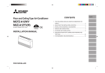
5. OUTDOOR UNIT INSTALLATION
INDOOR/OUTDOOR UNIT CONNECTING WIRE CONNECTION AND OUTDOOR POWER SUPPLY CORD
CONNECTION
•
•
Drain hose
INDOOR UNIT INSTALLATION
Insert the drain hose into the wall hole sleeve , and hook the upper part of
indoor unit on the installation plate . Then, move the unit to the very edge of the
left side for putting the piping easily in the back space of the indoor unit. After that,
cut the part of packing material (spacer assembly) to hook it on the back rib and
lift the indoor unit as shown in the figure below.
Rated Voltage Breaker capacity Connect to the supply terminals and leave a contact
separation of at least 3 mm at each pole to disconnect the source power pole. (When the power switch
230 V
20 A
is shut off, it must disconnect all poles.)
•
•
•
•
Cut part of packing material (spacer assembly) to
hook it on the back rib.
•
•
Spacer assembly
Spacer
Connect the refrigerant piping with the extension pipe .
Thrust the lower part of the indoor unit into the installation plate
•
15 mm
35 mm
For the indoor/outdoor unit connecting wires, be sure to use the ones in compliance
with the standards.
Be sure to push the core until it is hidden and pull each cable to make sure that it
is not pulled up incomplete insertion may cause a risk of burning the terminal
blocks.
Indoor and Outdoor
connecting wire
Specification
3-core 2.5 mm2 or more, in conformity with
Design 245 IEC 57.
3-core 4.0 mm2 or more, in conformity with
Design 245 IEC 57.
3-core 6.0 mm2 or more, in conformity with
Design 245 IEC 57.
•
•
Indoor terminal block
Loosen terminal screw.
Earth wire
(green/yellow)
Indoor/outdoor unit
connecting wire
4-core 1.0 mm2
Air
Water
leakage
Water
leakage
Lead wire
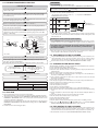
Waving
(Fig. 1)
(Fig. 2)
Terminal block
(Fig. 3)
L N
Outdoor terminal block
<Connection details>
Power supply cord
Tip of drain
hose dipped
in water.
Water
leakage
Less than
50 mm gap
•
•
3-core
CAUTION
•
•
•
•
Ditch
(Fig. 4)
25 m or less
A means for disconnection of the supply with an isolation switch, or similar
device, in all active conductors shall be incorporated in the fixed wiring.
Never cut the power cord and connect it to other wires.
It may cause a fire.
Accumulated
drain water
Do not raise.
15 m or less
WARNING
If the extension drain hose has to pass through a room, be sure to wrap it with
commercially sold insulation.
The drain hose should point downward for easy drain flow. (Fig. 1)
Do not make drain piping as shown in Fig. 2 to 5.
Downward slope
10 m or less
Cable 4-core 1.0 mm2, in conformity with
Design 245 IEC 57.
.
4-7 DRAIN PIPING
•
Peel off both ends of connecting wire (extension wire).
When too long, or connected by cutting off the middle,
peel off power supply wire to the size as shown in the
right.
Be careful not to contact connecting wire with piping.
Make earth wire a little longer than the others.
(more than 35 mm)
Power supply cord
Specification
Securely attach the spacer
assembly in the concave part
of the rib, taking care its
direction is correct as shown in
the right.
•
•
Connect the indoor/outdoor unit connecting wire
from the indoor unit correctly
on the terminal block.
For future servicing, give extra length to connecting wire.
(Fig. 5)
If the drain hose provided with the indoor unit is too short, connect it with drain hose
that should be provided at your site. (Fig.6)
When connecting the drain hose to the hard vinyi chloride pipe, be sure to insert it
securely into the pipe. (Fig.7)
Use care not to make mis-wiring.
Firmly tighten the terminal screws to prevent them from loosening.
After tightening, pull the wires lightly to confirm that they do not move.
If the connecting wire is incorrectly connected to the terminal block, the unit
does not operate normally.
Be sure to fix the indoor/outdoor unit
connecting wire
and power supply
cord
using this cord clamp.
Drain hose
Drain hose
Hard vinyl chloride pipe
I.D. 30 mm
70 cm
or more
(Fig. 6)
Soft hose
I.D.
15 mm Differentdiameter joint
Be sure to put the left
portion into the square
hole of the service panel.
Be sure to insert the
drain hose securely
into the pipe.
Service panel
(Fig. 7)
Fixing screws
Remove two fixing
screws to open the
service panel.
Valve cover
WARNING
Be sure to attach the service panel of the outdoor unit securely. If it is not attached
correctly, it could result in a fire or an electric shock due to dust, water, etc.
3 Putting nut on
6. INDOOR/OUTDOOR UNIT CONNECTION
FINISHING AND TEST RUN
•
INSTALLATION INFORMATION FOR THE AIR CONDITIONER WITH R410A REFRIGERANT
•
•
•
1
2
3
4
This room air conditioner adopts an HFC refrigerant (R410A) which will never destroy
the ozone layer.
Pay particular attention to the following points, though the basic installation
procedure is same as that for R22 air conditioners.
As R410A has a working pressure approx. 1.6 times as high as that of R22, some
special tools and piping parts / materials are required. (Refer to the table below.)
Take sufficient care not to allow water and other contaminations to enter the
R410A refrigerant during storage and installation, since it is more susceptible to
contaminations than R22.
For refrigerant piping, use clean, pressure-proof parts / materials specifically
designed for R410A. (Refer to 2. Refrigerant piping.)
Composition change may occur in R410A since it is a mixed refrigerant. When
charging, charge liquid refrigerant to prevent composition change.
Remove flare nuts attached to indoor and outdoor
units, then put them on pipe having completed
burr removal.
(not possible to put them on after flaring work)
Flare nut for R410A pipe differs from R22 pipe.
Refer to the following table for detail.
mm
inch
R410A
R22
1/4
17
17
ø9.52
3/8
22
22
ø12.7
1/2
26
24
ø15.88
5/8
29
27
4 Flaring work
•
Carry out flaring work using flaring tool as shown below.
A
Flaring tool
York
Die
Die
The following tools are required for R410A refrigerant. Some R22 tools can be
substituted for R410A tools.
The diameter of the service port on the stop valve in outdoor unit has been changed to
prevent any other refrigerant being charged into the unit. (Cap size has been changed
from 7/16 UNF with 20 threads to 1/2 UNF with 20 threads.)
Can R22 tools be used?
Gauge manifold
No
Wing nut type
Flare nut
R410A has high pressures beyond the measurement range of existing gauges.
Port diameters have been changed to prevent
any other refrigerant from being charged into the
unit.
Hose material and cap size have been changed
to improve the pressure resistance.
Gas leak detector
No
Dedicated for HFC refrigerant.
Yes
1/4 and 3/8
Copper pipe
A (mm)
Outside diameter
Conventional flare tool
Flare tool for R410A
clutch type
No
Torque wrench
Copper pipe
Clutch type
Description
Charge hose
Copper pipe
ø6.35
6-1 Tools dedicated for the air conditioner with R410A
refrigerant
R410A tools
Flare nut
•
Clutch type
Wing nut type
ø6.35 mm
0 to 0.5
1.0 to 1.5
1.5 to 2.0
ø9.52 mm
0 to 0.5
1.0 to 1.5
1.5 to 2.0
ø12.7 mm
0 to 0.5
1.0 to 1.5
2.0 to 2.5
ø15.88 mm
0 to 0.5
1.0 to 1.5
2.0 to 2.5
Firmly hold copper pipe in a die in the dimension shown in the table above.
5 Check
No
1/2 and 5/8
Flare tool
Yes
Clamp bar hole has been enlarged to reinforce
the spring strength in the tool.
Flare gauge
New
Provided for flaring work (to be used with R22
flare tool).
Vacuum pump
adaptor
New
Provided to prevent the back flow of oil. This
adapter enables you to use existing vacuum
pumps.
Electronic scale
for refrigerant
charging
New
It is difficult to measure R410A with a charging
cylinder because the refrigerant bubbles due to
high pressure and high-speed vaporization.
•
•
Compare the flared work with figure below.
If flare is noted to be defective, cut off the flared section and do flaring work again.
Smooth all around
Inside is shining without any scratches.
Even length
all around
No: Not substitutable for R410A Yes: Substitutable for R410A
6-3 PIPE CONNECTION
6-2 FLARING WORK
•
Main cause of gas leakage is defect in flaring work.
Carry out correct flaring work in the following procedure.
1 Pipe cutting
•
•
•
•
Cut the copper pipe correctly with pipe cutter.
No good
Copper pipe
Good
90°
Tilted
Uneven
Note:
Fasten a flare nut with a torque wrench as specified in the table below.
When fastened too tight, a flare nut may broken after a long period and cause a leakage
of refrigerant.
1 Indoor unit connection
Connect both liquid and gas pipings to indoor unit.
Apply a thin coat of refrigeration oil
on the seat surface of pipe.
For connection first align the center, then tighten the first 3 to 4 turns of flare nut.
Use tightening torque table below as a guideline for indoor unit side union joint
section, and tighten using two wrenches. Excessive tightening damages the flare
section.
Burred
Pipe diameter
ø6.35 mm
ø9.52 mm
ø12.7 mm
ø15.88 mm
2 Burrs removal
•
•
Completely remove all burrs from the cut cross section of pipe.
Put the end of the copper pipe to downward direction as you remove burrs in order to
avoid to let burrs drop in the piping.
Burr
Copper pipe
2 Outdoor unit connection
Connect pipes to stop valve pipe joint of the outdoor unit in the same manner applied for
indoor unit.
For tightening, use a torque wrench or spanner and use the same tightening torque
applied for indoor unit.
•
Spare
reamer
Pipe
cutter
Tightening torque
N·m
kgf·cm
13.7 to 17.7
140 to 180
34.3 to 41.2
350 to 420
49.0 to 56.4
500 to 575
73.5 to 78.4
750 to 800
INSULATION AND TAPING
1 Cover piping joints with pipe cover.
2 For outdoor unit side, surely insulate every piping including valves.
3 Using piping tape , apply taping starting from the entry of outdoor unit.
Stop the end of piping tape
with tape (with adhesive agent attached).
When piping have to be arranged through above ceiling, closet or where the
temperature and humidity are high, wind additional commercially sold insulation for
prevention of condensation.
•
•
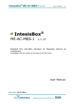
6-4 PURGING PROCEDURES·LEAK TEST
PROCEDURE
•
Press the EMERGENCY OPERATION switch.
1 Press it once, and after test run for 30 minutes the EMERGENCY COOL MODE starts.
PURGING PROCEDURES
Connect the refrigerant pipes (both liquid pipe and the gas pipe) between the indoor
and the outdoor unit.
Remove the service port cap of the stop valve on the side of the outdoor unit gas
pipe. (The stop valve will not work in it initial state fresh out of the factory (totally
closed with cap on).)
Connect the gauge manifold valve and the vacuum pump to the service port of the
stop valve on the gas pipe side of the outdoor unit.
If the left side lamp of the operation indicator blinks every 0.5 seconds, inspect the
indoor/outdoor unit connecting wire
for mis-wiring.
2 Press it once more, and the EMERGENCY HEAT MODE starts.
3 Press it once more, and the operation stops.
(The operation mode changes in order of 1 ~ 3 every time the EMERGENCY
OPERATION switch is pressed.)
Mode Operation Indicator lamp
1 COOL
Run the vacuum pump. (Vacuumize for more than 15 minutes.)
Check the vacuum with the gauge manifold valve, then close the gauge manifold
valve, and stop the vacuum pump.
Leave as it is for one or two minutes. Make sure the pointer gauge manifold valve
remains in the same position. Confirm that the pressure gauge shows–0.101 Mpa
[Gauge] (–760 mmHg).
Vacuum
pump
Window
Charge hose
(for R410A)
*4 to 5 turns
Adapter for
preventing
the back flow
(or the vacuum
pump with the
function to
prevent the
back flow)
•
After refrigerant pipes are connected and evacuated, fully open all stop valves on
both sides of gas pipe and liquid pipe.
Operating without fully opening lowers the performance and this causes trouble.
•
Tighten the cap to the service port to obtain the initial status.
Retighten the cap.
Leak test
Tightening torque
N·m
kgf·cm
Cap for service port
13.7 to 17.7
140 to 180
Cap for stop valve
19.6 to 29.4
200 to 300
6-5 TEST RUN
Before performing the test run, recheck any wrong wiring.
Wrong wiring prevents normal operation or results in blown fuse disabling operation.
The test run can be started by pressing EMERGENCY OPERATION switch. When the
EMERGENCY OPERATION switch is once pressed, the unit will start the test run
(continuous operation) for 30 minutes.
A thermostat does not work during this time. After 30 minutes the unit will start the
EMERGENCY OPERATION at a fixed temperature setting of 24°C in COOL MODE or
HEAT MODE.
Perform test run in the following procedure.
(Off)
(Off)
In starting the heating operation, indoor unit fan may not operate to prevent blowing
cool air. Please wait for a few minutes until the temperature of heat exchanger rises and
warm air blows out.
Once the compressor stops, the restart preventive device operates so the compressor
will not operate for three minutes to protect the air conditioner.
6-6 EXPLANATION TO THE CUSTOMER
•
Pipe length exceeding 7 m
Charge the prescribed amount
of gas. (refer to 3)
(Light)
If the indoor unit is operated with the remote controller, both the test
run and the emergency operation are released by commands from
the remote controller.
Remove the gauge manifold valve quickly from the service port of the stop valve.
Pipe length up to 7 m
No gas charge is needed.
(Off)
Press the ON/OFF button on the remote controller and check that an electronic sound is
heard from the indoor unit. Press the ON/OFF button again to turn the air conditioner off.
Charge hose
(for R410A)
Service port
EMERGENCY
OPERATION switch
HEAT
Checking the remote (infrared) signal reception
Handle High
Handle
Low
Stop
valve
Hexagonal wrench
•
•
Gauge manifold
valve (for R410A)
Stop valve
*Open
(Off)
3 STOP
-0.101MPa Compound pressure
Stop valve (-760 mmHg) gauge (for R410A)
Pressure gauge
(for R410A)
*Close
•
•
2
(Light)
Using the OPERATING INSTRUCTIONS, explain the following to the customer, how to
control temperature, how to remove the air filters, how to remove or put the remote
controller in the remote controller holder, how to clean, precautions for operation, etc.
Recommend the customer to read the OPERATING INSTRUCTIONS carefully.
6-7 CHECKING AFTER INSTALLATION
After finishing the installation, check the following items and mark the next to each item.
Is the specified power supply voltage used?
Is the power line equipped with the circuit breaker?
Have the ends of the indoor/outdoor connecting wire been properly inserted into the
terminal blocks?
Has the indoor/outdoor connecting wire been secured firmly?
Are the power supply cord and indoor/outdoor connecting wire connected directly to
the units (no intermediate connections)?
Is the earth wire longer than the other wires so that it will not become disconnected
when tension is applied?
Is the earth wire connected properly?
Are the pipes designed for use with R410A or do they have the specified thickness?
Has the leak test been carried out for the pipe connections?
Has air purging been carried out?
Are the stop valves open fully?
Is the drain hose properly installed?
Has water been poured through the drain hose to confirm proper drainage?
Are the pipes at the rear of the unit bundled with felt tape (for left and left-rear piping
only)?
Can the installation location bear the weight of the unit and not amplify its vibration or
noise?
Is the area under the unit free of objects that block the air outlet?
Are the vertical and horizontal vanes closed securely?
Is the front panel installed securely?
Has the test run been carried out?
Has the drain work been performed properly and are there no bubbling sounds?
Have all of the
WARNING and
CAUTION items in “1. THE FOLLOWING
SHOULD ALWAYS BE OBSERVED FOR SAFETY” been checked?
6-8 EXPLANATION TO THE CUSTOMER
•
•
Using the OPERATING INSTRUCTIONS, explain the following to the customer, how to
control temperature, how to remove the air filters, how to remove or put the remote
controller in the remote controller holder, how to clean, precautions for operation, etc.
Recommend the customer to read the OPERATING INSTRUCTIONS carefully.
7. FOR MOVEMENT AND MAINTENANCE
7-1 REMOVING AND REINSTALLING THE FRONT PANEL
FRONT PANEL REMOVAL
4 Release the hooks.
7-4 GAS CHARGE
1 Connect gas cylinder to the service port of stop valve (3-way).
2 Execute air purge of the pipe (or hose) coming from refrigerant gas cylinder.
3 Replenish specified amount of the refrigerant, while operating the air conditioner
for cooling.
Note:
In case of adding refrigerant, comply with the quantity specified for the refrigerating
cycle.
CAUTION
•
1 Remove the screw caps.
2 Remove three screws.
Hold this concave section and pull the bottom
forward to remove the front panel.
3 Pull the bottom.
FRONT PANEL REINSTALLATION
Note:
Do not open the front panel up beyond the level position.
The panel may come off in order to prevent it from being damaged.
1 Set the horizontal vane to the position as below before reinstalling the front
panel.
•
Do not discharge the refrigerant into the atmosphere.
Take care not to discharge refrigerant into the atmosphere during installation,
reinstallation, or repairs to the refrigerant circuit.
When charging the refrigerant system with additional refrigerant, be sure
to use liquid refrigerant.
Adding gas refrigerant may change the composition of the refrigerant in the
system and affect normal operation of the air conditioner. Also, charge the
system slowly, otherwise the compressor will be locked.
To maintain the high pressure of the gas cylinder, warm the gas cylinder with warm
water (under 40°C) during cold season. But never use naked fire or steam.
3
5 Push
Union
1 Point the
horizontal
vane slightly
downward.
Stop valve
Indoor unit
Liquid pipe
Gas pipe
2 4
Horizontal vane
2
3
4
5
Attach the bottom of the front panel under the horizontal vane.
Fit in the top of the front panel.
Fit in the bottom of the front panel and tighten it using screws.
Push the section of the front panel marked by the arrow and fit the panel into the
air conditioner.
Refrigerant gas
cylinder operating
valve
Outdoor unit
Service port
Gauge manifold valve
(for R410A)
Charge hose (for R410A)
Refrigerant gas cylinder for
R410A with siphon
7-2 PUMPING DOWN
When relocating or disposing of the air conditioner, pump down the system following
the procedure below so that no refrigerant is released into the atmosphere.
1 Connect the gauge manifold valve to the service port of the stop valve on the gas
pipe side of the outdoor unit.
2 Fully close the stop valve on the liquid pipe side of the outdoor unit.
3 Close the stop valve on the gas pipe side of the outdoor unit almost completely
so that it can be easily closed fully when the pressure gauge shows —0.101 MPa
[Gauge] (0 kgf/cm2).
4 Start the EMERGENCY COOLING OPERATION.
To start the EMERGENCY OPERATION in COOL MODE, disconnect the power
supply plug and/or turn off the breaker. After 15 seconds, connect the power
supply plug and/or turn on the breaker, and then press the EMERGENCY
OPERATION switch once. (The EMERGENCY COOLING OPERATION can be
performed continuously for up to 30 minutes.)
5 Fully close the stop valve on the gas pipe side of the outdoor unit when the
pressure gauge shows 0.05 to 0 MPa [Gauge] (approx. 0.5 to 0 kgf/cm2).
6 Stop the EMERGENCY COOLING OPERATION.
Press the EMERGENCY OPERATION switch twice to stop the operation.
Refrigerant (liquid)
Electronic scale for
refrigerant charging
7-3 REMOVING THE INDOOR UNIT
Remove the bottom of the indoor unit from the installation plate.
1 Remove the front panel. (See FRONT PANEL REMOVAL shown above.)
2 Insert flat screwdrivers into the square holes at the left and right bottom of the
indoor unit and push them up; the bottom of the indoor unit goes down and the
hooks are released.
Push
Go down
Square hole
HEAD OFFICE: TOKYO BLDG., 2-7-3, MARUNOUCHI, CHIYODAKU, TOKYO
100-8310, JAPAN