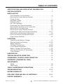
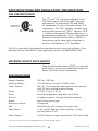
1
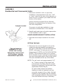
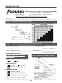
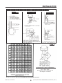
SRE-1550 ELECTRA-RIDE™ II STAIRWAY ELEVATOR Technical Service email: [email protected] www.bruno.com DEALER: INSTALLATION MANUAL MAN-1550-1 03-18-2008 1780 EXECUTIVE DR., P.O. BOX 84, OCONOMOWOC, WI 53066 USA TELEPHONE:(262) 567-4990 FAX: (262) 953-5501 1-800-882-8183 IMPORTANT NOTES The warranty for the Electra-Ride™ II Stairway Elevator is rendered null and void if the unit is installed by anyone other than an authorized Bruno dealer. This stairway elevator is intended for indoor use only in a heated, enclosed location above 35 F (2 C). ™ ™ Electra-Ride is a trademark of Bruno Independent Living Aids, Inc.®. The Electra-Ride II, #5,230,405 is covered by one or more U.S. Patents and/or U.S. Patents Pending. ©2008,1996 BRUNO INDEPENDENT LIVING AIDS, INC.® 2 SRE-1550 03-18-2008 TABLE OF CONTENTS SPECIFICATIONS AND REGULATORY INFORMATION. . . . . . . . . . 4 CARTON CONTENTS. . . . . . . . . . . . . . . . . . . . . . . . . . . . . . . . . . . 5 INSTALLATION Tools Necessary for Installation . . . . . . . . . . . . . . . . . . . . . . . . . 6 Mounting the Lower Bumper Bracket . . . . . . . . . . . . . . . . . . . . . 7 Fitting the Rail. . . . . . . . . . . . . . . . . . . . . . . . . . . . . . . . . . . . . 7 Application Guide. . . . . . . . . . . . . . . . . . . . . . . . . . . . . . . . . . 8-9 Cutting the Rail . . . . . . . . . . . . . . . . . . . . . . . . . . . . . . . . . . . 10 Rail Joint Assembly. . . . . . . . . . . . . . . . . . . . . . . . . . . . . . . . . 11 Positioning Foot Clamp Assemblies. . . . . . . . . . . . . . . . . . . . . . 12 Mounting the Carriage on the Upper Rail. . . . . . . . . . . . . . . . . . 13 Adjusting the Carriage Angle. . . . . . . . . . . . . . . . . . . . . . . . . . 13 Mounting the Upper Bumper Bracket. . . . . . . . . . . . . . . . . . . . . 14 Installing the Seat and Footrest Assemblies. . . . . . . . . . . . . . 16-17 Seat Swivel and Seat Arm Adjustment . . . . . . . . . . . . . . . . . . . 18 Final Limit Switch and Ramp Actuation . . . . . . . . . . . . . . . . . 19-20 Upper Bumper Bracket . . . . . . . . . . . . . . . . . . . . . . . . . . . . . . 24 ELECTRICAL Connecting the Battery Charger. . . . . . . . . . . . . . . . . . . . . . . . 14 Routing the Wiring Harness. . . . . . . . . . . . . . . . . . . . . . . . . 14-15 Safety Switches. . . . . . . . . . . . . . . . . . . . . . . . . . . . . . . . . . . 17 Call/Send Transmitters. . . . . . . . . . . . . . . . . . . . . . . . . . . . 19-23 Circuit Board Diagnostics. . . . . . . . . . . . . . . . . . . . . . . . . . . 24-25 Battery Charger LED's and Fuse. . . . . . . . . . . . . . . . . . . . . . . . 26 Learning the Remote IR Transmitter. . . . . . . . . . . . . . . . . . . 27-28 Circuit Breaker. . . . . . . . . . . . . . . . . . . . . . . . . . . . . . . . . . . . 28 LUBRICATION . . . . . . . . . . . . . . . . . . . . . . . . . . . . . . . . . . . . . . 29 TESTING ELEVATOR OPERATION. . . . . . . . . . . . . . . . . . . . . . . . 30 CONVERSION TO RIGHT-HAND OPERATION . . . . . . . . . . . . . . . 31 OVERSPEED (COMMERCIAL ONLY). . . . . . . . . . . . . . . . . . . . . . . 32 ADJUSTMENTS Speed. . . . . . . . . . . . . . . . . . . . . . . . . . . . . . . . . . . . . . . . . . 33 Seat Height. . . . . . . . . . . . . . . . . . . . . . . . . . . . . . . . . . . . . . 33 YEARLY MAINTENANCE OPERATIONS . . . . . . . . . . . . . . . . . . . . 34 TROUBLESHOOTING. . . . . . . . . . . . . . . . . . . . . . . . . . . . . . . . 35-36 WIRING SCHEMATIC . . . . . . . . . . . . . . . . . . . . . . . . . . . . . . . . . 37 EXPLODED VIEW AND BILL OF MATERIALS. . . . . . . . . . . . . . 38-41 LIMITED WARRANTY. . . . . . . . . . . . . . . . . . . . . . . . . . . . . . . . . 42 SRE-1550 03-18-2008 3 ©2008,1996 BRUNO INDEPENDENT LIVING AIDS, INC.® SPECIFICATIONS AND REGULATORY INFORMATION CSA CERTIFICATION ® 208135 C US The "C" and "US" indicators adjacent to the CSA Mark signify that the product has been evaluated to the applicable CSA and ANSI/ UL Standards, for use in Canada and the U.S., respectively. This "US" indicator includes products eligible to bear the "NRTL" indicator. NRTL, i.e. National Recognized Testing Laboratory, is a designation granted by the U.S. Occupational Safety and Health Administration (OSHA) to laboratories which have been recognized to perform certification to U.S. Standards. This lift is intended to be installed in accordance with the current editions of the National Electric Code NFPA-70 and applicable sections of ANSI/ASME A18.1. MATERIAL SAFETY DATA SHEETS Material safety data sheets (MSDS) on materials used on this unit may be requested through the Bruno Technical Service Department. SPECIFICATIONS Weight Capacity: Variable Speed: Power Source : Motor: Drive: Control: Brake: Maximum Incline: Rail: Seat Swivel: Power Supply: 350 lbs. (159 kg) 0 to 38 feet per minute (0 to12 m/mn) two (2) 12-volt sealed, maintenance-free batteries with 24-volt continuous-duty charger 24 VDC, 2-pole, 1.02 hp self-locking gearbox, rack and pinion drive constant pressure (armrest and two remotes) self-locking worm gear 45 degrees steel channel with integral drive gear rack 0, 45, and 90 degrees, both directions, at top and at bottom of rail 24 VDC battery charger powered by 120V wall outlet This unit is covered by one or more US Patents and/or has U.S. Patents Pending. ©2008,1996 BRUNO INDEPENDENT LIVING AIDS, INC.® 4 SRE-1550 03-18-2008 CARTON CONTENTS The ELECTRA-RIDETM II is shipped in 5 cartons. Check the contents of the cartons against the list below to be sure you have all of the components before beginning an installation. Report any discrepancies to Bruno Independent Living Aids immediately. Also, check the carton contents for shipping damage upon receipt. Damage claims must be filed by the dealer, not the manufacturer. Bruno Independent Living Aids cannot be held responsible for shipping damage. CARRIAGE BOX (1) (4) (2) (2) complete carriage assembly Velcro® strips (2.5" ea.) call/send transmitters mounting plates, call/send transmitters (1) call/send transmitters with hardware kit (2) SRE-K-2701 residential transmitters ---or--(2) SRE-K-0055A commercial call/send transmitters INSTALLATION BOX (1) tube white lithium grease (1) final limit switch ramp assembly (2) bumper assemblies (1) SRE-K-1553 bumper assembly parts kit (10) 11" lg wire ties (32) sheet metal screws (m 6.3 x 50 mm)(16' rail); (40) for (20' rail) clamp sets: • 9 (16' rail) • 11 (20' rail) • 13 (24' rail) • TBD** (custom rail) **depends upon rail length • upon request: clamps, adjustable, 9 lbs. ea. (1) SRE-K-1501 electrical parts kit SEAT BOX (1) seat assembly (1) footrest assembly (1) battery charger RAIL BOX ***NOTE: Rail sections must have matching numbers stamped on the sections. SRE-1550 03-18-2008 (1) ea. rail section *** RAIL BOX WITH JOINT PLATE (1) ea. (1) ea. rail section *** joint plate (1) SRE-K-1502 hardware kit (joint plate) 5 ©2008,1996 BRUNO INDEPENDENT LIVING AIDS, INC.® INSTALLATION Necessary Tools • protractor level, builder's level • socket set, metric (10 mm through 22 m) Be sure you have all necessary parts and tools before traveling to installation site. • ratchet, with 6" extension • combination wrench set, metric (22 mm through 36 mm) • Phillips screwdrivers • slotted screwdrivers • Allen wrenches, metric (4 mm minimum size) NOTE: • electric drill with letter `O' (.316") and 1/4" bit THE STANDARD STAIRWAY ELEVATOR • hacksaw with 2 or 3 blades, or metal cutting bandsaw IS SUITABLE FOR STAIRWAY ANGLES UP • 20' tape measure TO 45 DEGREES. • small rubber mallet • C-clamp • flashlight • 5/16" open-end wrench • needle nose pliers • scissors or knife • extension cord • double-sided foam tape • file • 12" adjustable wrench • additional hardware for installation on floor surface(s) other than wood Bruno ships the Stairway Elevator with fasteners appropriate for WOODEN STAIR TREADS ONLY. Other stair material may require different fasteners. Please contact Bruno Independent Living Aids, Inc. for information. ©2008,1996 BRUNO INDEPENDENT LIVING AIDS, INC.® 6 SRE-1550 03-18-2008 INSTALLATION ASSEMBLY Residential and Commercial Units 1. D etermine whether a left- or right-side installation is appropriate for the site. "Left" or "right" refers to the side of the stairway on which the rail is installed (as viewed from the bottom of the stairs). bumper bracket Unless otherwise specified Bruno Stairway Elevators are shipped from the factory in the left-side configuration. Conversion to right-side installation is easy (instructions included later in this manual). 2. I dentify and locate lower rail section appropriate to the installation (left or right). LOWER BUMPER BRACKET INSTALLATION 1. A ssemble the bumper bracket to the lower rail. FITTING THE RAIL This rail must be installed 1/2" to 1" above stair nosing. Otherwise, footrest will hit the steps, causing intermittent operation. 1. D etermine the correct length for the rail by measuring along a straight line placed on the stairs. (SEE STEP 2 IN THE APPLICATION GUIDE, next page) To that amount, add Measurement B (STEP 4 IN THE APPLICATION GUIDE). This process will allow you to custom fit the elevator to your customer by determining the most comfortable seat-to-floor height within the space available at the top of the stairs. NOTE: T he rail must rest approximately 1/2" to 1" above nosing of the steps and extend from the lower floor to a point beyond the nosing of the top step (see Application Guide Step 4). In some cases where the bottom landing is made of material such as concrete, ceramic tile or slate, the last bracket on the landing may be omitted with a bracket added on the second step from the bottom and top of stairway. SRE-1550 03-18-2008 7 ©2008,1996 BRUNO INDEPENDENT LIVING AIDS, INC.® INSTALLATION 1780 Executive Drive, P.O. Box 84, Oconomowoc, WI 53066 USA Tel.: (262) 567-4990 1-800-882-8183 Fax: (262) 953-5501 www.bruno.com Straight Stairway Elevator Application Guide Dealer No.: _______ P.O. No. _______ Customer: __________ Date: ________ Step 1: Determine Staircase Angle Step 2: Define Stairway Dimensions and Details stair tread material ____________________ staircase width ___________________ (32” min. for standard unit) lower landing material_________________obstructions______________________ (ex. handrails, moldings) upper landing material__________________ Step 3: Specify Chair and Rail Details Step 4: Determine Rail Length hand (looking from bottom of stairs): left right chair upholstery tan vinyl tan fabric other (specify) __________ additional options keyswitch on chair keyed call/send transmitters commercial/overspeed package Refer to Step 3 on following pages. ©2008,1996 BRUNO INDEPENDENT LIVING AIDS, INC.® 8 SRE-1550 03-18-2008 INSTALLATION Step 3: SRE-1550 ELECTRA-RIDE™ APPLICATION DETAILS TOP VIEW FRONT VIEWS SIDE VIEWS Step 4 alternate seat height dimensions Measured @ Lower Level: 23.5”, 24.5”, 25.5” Reduce B by 1.5” for each inch the seat height is increased. SRE-1550 03-18-2008 9 ©2008,1996 BRUNO INDEPENDENT LIVING AIDS, INC.® INSTALLATION CUTTING THE RAIL-Residential and Commercial Units NEVER CUT OFF THE JOINT END! The M6 bolts securing the gear rack must remain intact. Cut off the end with the pre-drilled charge contact mounting holes. Then, using the provided template, redrill (2) holes on each end of the rail. IMPORTANT NOTE! Under no circumstances should a rail section be cut shorter than 18” (46 cm). There must be at least (2) clamps on a short rail section (one at the rail joint and one at the rail end). Cutting a rail shorter than 18” (46 cm) would not allow enough room for the (2) necessary clamps. Example: After measuring the staircase, you determine you need 9 feet of rail. From your (2) 8-foot sections you decide to use (1) 8-foot section and cut the remaining one foot from the second 8-foot section. Doing this could yield a rail piece with insufficient weld. Instead, Bruno recommends cutting at least one foot off one of the 8-foot sections (leaving 7 feet of rail) and then cutting two feet from the second 8-foot section. You will have a (1) 7-foot section and (1) 2-foot section, both of which are long enough to be properly mounted (2 clamps minimum per short rail). 1. U se a metal-cutting power saw or manual hacksaw to cut the rail to length. Cut off the end of the rail to be located at the top of the stairway. 2. U se a file or other appropriate tool to deburr the cut end of the rail. Soften any sharp edges which might abrade the insulation of the wiring to be routed to the bumper at the end of the rail. 3. U se a C-clamp to hold the upper bumper bracket in place in the cut end of the rail. USE “O” SIZE DRILL BIT (8.03mm/.316") 4. U se the holes in the bumper bracket as guides to drill mounting holes. Use an O-size (8.03 mm/.316") drill bit in the rail. ©2008,1996 BRUNO INDEPENDENT LIVING AIDS, INC.® 10 SRE-1550 03-18-2008 INSTALLATION RAIL JOINT ASSEMBLY-Residential and Commercial Units NOTE Always install the rail with the gear rack towards the center of the stairs and the gear teeth facing wall. NOTE The chamfered edges of the holes must face "up" toward the bottom of the rail. 1. A ssemble the rail joint by attaching the bottom plate to the rail with the screws, lock washers and hex nuts provided with the unit. 2. I nstall the bolts, internal-tooth washers and hex nuts through the joint blocks on both sides of the rail. 3. T ighten all bolts securely and make sure screw heads are flush with the surface of the inside of the rail. Once two sections of rail are installed, and before installing the carriage, run a plomb line along the rail. If the rail bows, insert shims or readjust clamps. SRE-1550 03-18-2008 11 ©2008,1996 BRUNO INDEPENDENT LIVING AIDS, INC.® INSTALLATION POSITIONING FOOT CLAMP ASSEMBLIES-Residential and Commercial Units •I nstall foot clamps at least 1-1/2” (38 mm) from wall. •P rovide additional clearance if seat needs to swivel against wall. •B efore securing all clamps, run carriage assembly up and down stairway to check seat clearance over the entire travel length. 1. I nstall rail mounting foot clamps in the placement pattern shown to the left. Leave a minimum space of 1-1/2" (38 mm) from the wall. 2. F or ease of installation, finger tighten all clamps to rail. Position the clamp assembly so the nut is closest to the wall. Foot Clamp Placement • • • • • bottom landing first tread up from bottom landing top landing first tread down from top landing closest tread above and below rail joint(s) • minimum of every third tread over the remainder of the staircase. NOTE: If top or bottom clamp is omitted because the landing is cement or ceramic tile, or if the owner wishes not to drill holes in the landing, a set of clamps should be added on the second-to- last step and at the top of stairway. 3. S lide top and bottom clamps down until firmly seated on step. When installing on carpeted stairs, tap the clamps with a rubber mallet to compress carpet and cushion before anchoring to steps. 4. S ecurely install one screw near the wall on the top and bottom of foot of clamp assemblies. This will enable the installer to change the position of the rail if necessary and prevent drilling excess holes. rail 1/2" to 1" (13-25 mm) above nosing rail mounting foot clamp assembly If threaded fastener extends below a stair tread that is exposed, it can be trimmed flush with pliers. ©2008,1996 BRUNO INDEPENDENT LIVING AIDS, INC.® 12 SRE-1550 03-18-2008 INSTALLATION MOUNTING CARRIAGE ON UPPER RAIL Residential and Commercial Units 1. T urn toggle switch off. When facing the front of the unit, remove the left motor cover. 2. S lide the carriage into the rail until the spur gear rests on the gear rack. 3. M anually turn the motor pulley to fully engage the entire carriage inside the upper rail. circuit breaker with built-in ON/OFF switch ADJUSTING THE CARRIAGE ANGLE Residential and Commercial Units angle adjustment bracket 1. A djust the carriage angle by loosening the angle adjustment bolts. Level the angle adjustment bracket, using a standard builder's level or protractor level. 2. W hen the angle adjustment bracket is level, securely tighten all four angle adjustment bolts*. TORQUE RATING = 70 LB-FT angle adjustment bolts SRE-1550 03-18-2008 13 ©2008,1996 BRUNO INDEPENDENT LIVING AIDS, INC.® INSTALLATION UPPER BUMPER BRACKET 1. I nstall the upper bumper bracket to rail. 2. B efore tightening the bracket, check to make sure that the bumper wires are not trapped under the bumper bracket at the lower landing. 3. Tighten the bracket. CONNECTING THE BATTERY CHARGER AND ROUTING THE WIRING HARNESS 1. P osition the charger in a suitable permanent location where it will not create a tripping hazard. After routing the wire harness out of sight, 2. Route the battery charger wiring a small piece of double sided foam tape harness along the back side of the rail. can be applied to the harness plugs for attachment under the rail. Note: If the charger plug and wire are located in a vulnerable location, use of a plug lock is recommended to prevent accidental unplugging. Plug locks are available at hardware and department stores. Choose one of these (2) mounting holes 3. S ecure this harness to the rail clamps with wire ties or double-sided tape (see note to left). Be sure that this wiring is mounted securely to avoid damage. 4. S ecure the charger in the chosen location (Step 1) by inserting (2) screws (provided) through the mounting holes in the charger base. NOTE: There are (2) mounting holes on each side of the charger base. Choose one of the two on each side. Choose one of these (2) mounting holes ©2008,1996 BRUNO INDEPENDENT LIVING AIDS, INC.® 14 SRE-1550 03-18-2008 INSTALLATION elevator charge bumper 5. C onnect the charger power cord to the nearest wall or floor outlet. 6. C onnect the charger wiring harness to the elevator power cable. 7. Bundle together loose wires. charger power cord elevator power cable 8. Turn ON the charger power switch. + charger power switch NOTES: •T he charger should be plugged into a household outlet all of the time. • The elevator is designed so that the batteries will be charged when the carriage is at either end of the rail. connect charger wiring harness to elevator power cable elevator charge bumper • I t is imperative that the carriage be “parked” at the end of the rail when it is not in use to maintain full battery charge. • I f the stairway elevator cannot be parked at one end of the rail (for example, on stairways with a door at the top), use the remote call/send transmitter to send the carriage to the other end. In this way, the carriage will properly engage the charging contacts, ensuring that the batteries will remain fully charged. SRE-1550 03-18-2008 15 ©2008,1996 BRUNO INDEPENDENT LIVING AIDS, INC.® INSTALLATION INSTALLING THE SEAT ASSEMBLY Residential and Commercial Units 1. F eed the five-conductor lead through the hollow tube under the seat. 2. I nsert the seat frame post into the outer mounting tube. 3. D etermine the correct seat height, then insert the bolt in the corresponding hole. Make sure the head of the bolt protrudes 3/8" (9.5 mm) from the mounting tube. 4. F ish the excess wires into the hole on front pivot bolt. outer mounting tube bolt protrudes 3/8" (9.5 mm) front pivot bolt Optional Large Seat with Fixed Arms (1540 Style) ©2008,1996 BRUNO INDEPENDENT LIVING AIDS, INC.® 16 SRE-1550 03-18-2008 INSTALLATION FOOTREST ASSEMBLY-Residential and Commercial Units 1. C onnect the wires as shown to the right. pivot bolt 2. T uck the excess wires in the footrest hanger just above the footrest switch bracket, and below where the outer mounting tube would sit. 3. W hile holding the wires in place, bring the footrest close to the carriage, near the pivot bolt, and tilt the footrest slightly while raising it up and over the bolt until it is engaged in the slot. footrest switch bracket set screws footrest outer mounting tube 4. T ighten the bolt, then the (2) set screws at the top of the footrest post (see illustration below) to completely secure the seat post. footrest hanger safety switch DO NOT PINCH THE WIRES WHILE SLIDING THE FOOTEST OVER THE BOLT. SAFETY SWITCHES-Residential and Commercial Units Safety switches are located on each side of the footrest, and on each side of the carriage. footrest safety switch (one also located on other side) The footrest safety switches will stop the elevator if they contact an object as the unit moves up/down the rail. 1. C onfirm correct operation of the footrest safety switches by moving the sliding tray (BOTH SIDES) while operating the elevator. The carriage safety switches (one on each side of the carriage) stop the elevator when the unit reaches the end of the rail. 1. C onfirm correct operation of the carriage safety switches by running the elevator to the top and bottom of the rail. carriage safety switch (one also located on other side) SRE-1550 03-18-2008 17 ©2008,1996 BRUNO INDEPENDENT LIVING AIDS, INC.® INSTALLATION SEAT SWIVEL AND ARM ROTATION-Residential and Commercial Units 1. F old the seat up when the Elevator is not in use. 2. T o unfold the seat when ready to use the Elevator, simply push down the seat, or the arm rest. push up latch to swivel seat The swivel latch located directly under the seat allows the seat to rotate in 45-degree increments. 3. T o disengage the latch, lift up on either the right or left lever found at the front edge of the seat. 4. R elease the lever to lock the seat in place. 5. P ush the arm lock lever to rotate the arm up to 90 degrees for easy transfer. The arm then can be rotated back to its original position. The arm locks in place automatically when the latch re-engages. ARM ADJUSTMENT-Residential and Commercial Units If you are not adjusting the arm, skip to Step No. 4. arm lock release arm lock release PSM-10002 screws 1. T o adjust to a wider setting, loosen the arm adjustment screws on the bottom of the seat (see left). 2. R otate the arm out to the desired position. 3. Tighten the arm adjustment screws. arm adjustment screws 4. S crew (2) PSM-10002 into the seat bottom to lock the armrest in place. If extending the arms to maximum width, be sure to adjust the rail-towall distance to compensate for the increased angle of rotation. ©2008,1996 BRUNO INDEPENDENT LIVING AIDS, INC.® 18 SRE-1550 03-18-2008 INSTALLATION FINAL LIMIT SWITCH AND ACTUATION RAMP Residential and Commercial Units 1" 8" LH RH The final limit switch and actuation ramp assembly is safety features which enhance the stopping capability of the Elevator. 1. M ount the actuation ramp to the side of the rail, 1" (25 mm) from the top of the rail in a LEFT-HAND installation. tighten M6 x 10 hex head cap screws Measure the distance from the end of the rail to the inside edge of the actuation ramp. In a RIGHT-HAND installation mount the ramp 8" (203 mm) from the top end of the rail. 2. T ighten M6 X 10 hex head screws on bottom of ramp. 3. T he limit switches on the end of the carriages require adjustment (see illustration below). FAILURE TO ADJUST LIMIT SWITCHES WILL INTERFERE WITH UNIT CHARGING . •S horten the switch on the lower end of the carriage. •L engthen the switch on the upper end of the carriage. SRE-1550 03-18-2008 19 ©2008,1996 BRUNO INDEPENDENT LIVING AIDS, INC.® INSTALLATION 1. Remove the seat. 2. Remove the carriage from the rail. 3. T o adjust the limit switches, remove the covers and rotate the angle adjustment bracket weldment, if necessary, to access the limit switches. limit switch adjustment 4. L oosen the limit switches using a 9/16" box wrench on the outside nut and a 5/8" open end wrench on the inside nut. It may also be necessary to use a pair of needle nose pliers. 5. T o access the limit switch on the motor side, it may be necessary to remove the charge contact assembly. a. R emove wire tie on the charge contact. b. Slide the charge contact out of the way, being careful to keep wires connected. c. R emove the outer nut on the limit switch. d. S lide the limit switch out to provide access to the inside nut for adjustment. e. Tighten and reinstall parts. f. Replace covers. g. A djust the angle adjustment bracket. h. Replace unit on rail. i. T est that the unit charges correctly. charge contact Make sure contacts make solid contact with rail end when carriage stops at top or bottom of rail. ©2008,1996 BRUNO INDEPENDENT LIVING AIDS, INC.® 20 SRE-1550 03-18-2008 ELECTRICAL RESIDENTIAL INFRARED CALL/SEND TRANSMITTER The call/send system on the Bruno SRE-1550 is based on infrared (IR) controls. Like a television remote, the SRE-1550 hand-held transmitter may experience certain types of interference. Receivers are mounted on both sides of the SRE-1550 carriage to minimize interference. Should interference occur, the unit will stop. This feature has been integrated into the SRE-1550 to ensure your safety. The direct line between the transmitter to either of the (2) transmitters should be clear of obstacles for optimal operation. It may be necessary to reposition the transmitters so that they are aimed at the carriage. To reduce the possibility of interference: •W hile riding in the seat, ALWAYS operate the Elevator using the rocker switch on the armrest. Operating the SRE-1550 with a transmitter while riding in the seat can lead to signal interference. •D O NOT mount the transmitters behind an obstacle such as a rail post. •D O NOT allow direct sunlight to shine on the receivers (blinding the receivers on the carriage). • DO replace transmitter batteries regularly. Depleted or nearly-depleted batteries alter the effective range of the transmitter. •D O keep the transmitter and receiver lens free of dirt and debris. Use a non-abrasive cleaner suitable for glass or acrylic surfaces. Do not use polishes or cleaning products containing wax.These products will leave a film on the lens that will reduce the signal transmission range. SRE-1550 03-18-2008 21 ©2008,1996 BRUNO INDEPENDENT LIVING AIDS, INC.® ELECTRICAL CALL/SEND TRANSMITTER-RESIDENTIAL Mounting the standard infrared call/ send transmitter Mounting with bracket and hardware: 1. M ount the bracket to the back of the transmitter using the (4) screws provided. 2. P osition the bracket/transmitter unit in the mounting location on the wall and mark the top and bottom bracket holes. 3. D rill a pilot hole slightly smaller than the anchors provided. 4. G ently pound the anchors into the wall with a rubber mallet. 5. P osition the bracket/transmitter unit on the wall so that the top/bottom bracket holes align with the anchors. 6. S ecure the bracket/transmitter to the wall using the screws provided. TESTING THE CALL/SEND TRANSMITTER Soft Start Feature The controller includes a soft start feature which causes a short delay between the time the rocker switch on the armrest is depressed and the initiation of carriage movement. This is normal! 1. U sing the rocker switch on the seat armrest, run the unit up and down the rail. NOTE: T he unit should travel noticeably faster going up than down. 2. Check for smooth operation and travel. 3. N ow, using one of the remote call/send transmitters, run the unit up and down the rail. 4. Repeat Step 3 with the other transmitter. 5. Check for smooth operation and travel. ©2008,1996 BRUNO INDEPENDENT LIVING AIDS, INC.® 22 SRE-1550 03-18-2008 ELECTRICAL CALL/SEND TRANSMITTER-COMMERCIAL 1. I nstall the key-controlled call/send transmitters as shown below. The key switch should be approximately 48" (122 cm) from the floor. 2. I nstall one transmitter at the top of the stairs, and one at the bottom. 3. T he seat key switch and rocker switch are located under the right arm pad (on your right as you are sitting in the seat). Please refer to the instructions "Changing Controls From Right to Left Armrest" if the unit will be installed on the right side of the stairway (as viewed from the bottom of the stairs). INSTALLLING COMMERCIAL CALL/SEND TRANSMITTER SRE-1550 03-18-2008 23 ©2008,1996 BRUNO INDEPENDENT LIVING AIDS, INC.® ELECTRICAL CIRCUIT BOARD DIAGNOSTICS The circuit board provided on the SRE-1550 is equipped with (4) diagnostic modes that continuously monitor the unit’s operation. This choice of operational modes allows the SRE-1550 to respond to the requirements of a wide variety of installations. NOTE : T he SRE-1550 is shipped in the MULTI-USER/DIAGNOSTIC MODE. MULTI-USER/DIAGNOSTIC MODE Provides full range of Audio diagnostic notices: *Circuit Board Power Up: Chirp *Safety Device Activated: Chirp *Elevator Stopped Off Charge Bumper: 5 Beeps (4 short and 1 long) Repeats every 3 minutes until the Elevator is returned to the bumper. *Seat Safety Disengaged: Chirp repeats every 3 seconds until seat safety switch is re-engaged. *Battery Voltage Drop: 5 Beeps (3 short and 2 long) Repeats every 4 minutes until seat safety switch is disengaged, the battery voltage increases, or the switch is pressed. *Battery Voltage Critical: 5 Beeps (2 short and 3 long) Repeats once a minute until the voltage exceeds 16V or the switch is pressed. *Switch Active During Power Up: 3 Beeps / Pause Repeats beeps every 5 seconds until all switches are off. *More Than One Switch Active: 3 Beeps / Pause/X beeps (number of beeps indicates which switches are active) Repeats every 30 seconds until all switches are off. *Transmitter ID Memory Full: 3 Beeps (1 short and 2 long) SINGLE-USER MODE Provides the same audio diagnostic notices as the Multi-User/Diagnostic Mode, except for the Seat Safety Disengaged notice. QUIET MODE In the QUIETmode, none of the Audible Warning Messages is active. BATTERY WARNINGS ONLY MODE Provides battery audio diagnostic only. *Elevator Stopped Off Charge Bumper: 5 Beeps (4 short and 1 long) Repeats every 3 minutes until Elevator is returned to the bumper. *Battery Voltage Drop : 5 Beeps (3 short and 2 long) Repeats once every 4 minutes until the seat safety switch is disengaged or the battery voltage increases. *Battery Voltage Critical: 5 Beeps (2 short and 3 long) Repeats once a minute until voltage is above 16 V. ©2008,1996 BRUNO INDEPENDENT LIVING AIDS, INC.® 24 SRE-1550 03-18-2008 ELECTRICAL CIRCUIT BOARD DIAGNOSTICS AUDIO REFERENCE NOTICE: Before touching anything inside the carriage assembly, ground yourself by touching an unpainted metal surface on the unit such as an exposed bolt, or one of the mounting screws on the electrical panel. While you work, periodically touch an unpainted metal surface to dissipate any static electricity that could harm internal components. Chirp 0.25 seconds Short Beep 0.50 seconds Long Beep 1.50 seconds Pause 1.00 second Changing the PCB Diagnostic Mode 1. Turn the circuit breaker on the carriage to `OFF’. 2. Remove the left carriage cover. 3. T he unit is shipped in the Multi-User Diagnostic Mode. Changes are made via the Number 1 and Number 2 positions on the 4-Ganged DIP Switch. 4 GANGED DIP SWITCH DIP SWITCH POSITION DIAGNOSTIC MODE #1 #2 Multi-User OFF OFF Single-User OFF ON Quiet ON OFF Battery Warnings Only ON ON Other Circuit Board Features Also located on the 4-ganged DIP switch are switches #3 Installation and #4 Coast Delay. The coast delay option (Switch #4) has been provided in cases of interference which may cause intermittent operation. The normal setting is 600 mSec. of coast. Should the unit lose the remote call/send signal, this can be increased to 900 mSec. by moving Switch #4 to the `ON’ position. SRE-1550 03-18-2008 25 ©2008,1996 BRUNO INDEPENDENT LIVING AIDS, INC.® ELECTRICAL Battery charger LED’s charging power on RED ready YELLOW GREEN ON OFF OFF ON (5 sec.) ON (5 sec.) ON (5 sec.) ON ON OFF ON SLOW BLINK SLOW BLINK ON ON ON ON ON OFF (Vfloat >27.4V) BLINK OFF ON ON OFF FAST BLINK ON BLINK ON STATUS charger not connected to battery (AC power ON, no battery connected) battery disconnect situation detected (AC power ON, battery disconnect); 10-second delay until yellow and green LED’s completely off charger at maximum voltage/delivering maximum current batteries close to being fully charged batteries fully charged low voltage indication battery defective or heavily sulfated bad connection or batteries Battery Charger Fuse Replacement power switch fuse If the charger is subject to a power line surge, the AC input fuse may blow. Refer to the illustration to the left for fuse location. To replace fuse: 1. T urn OFF the battery charger power switch. 2. R emove power cord from wall outlet. 3. T wist the fuseholder cap and pull out to remove the fuse. 4. R eplace with the same size and type: (Bussmann GMD-2A or equivalent) 2A, Slo-Blow, 5x20 mm. ©2008,1996 BRUNO INDEPENDENT LIVING AIDS, INC.® 26 SRE-1550 03-18-2008 ELECTRICAL LEARNING THE REMOTE INFRARED TRANSMITTER (not necessary when installing unit for the first time) The operating channel of the two (2) infrared transmitters included with the SRE-2750 is pre-set at the Bruno factory. Reasons for relearning transmitters: • there are multiple units in the same location; • you have to replace transmitters. To relearn a transmitter: 1. Turn the circuit breaker OFF. 2. R emove the CARRIAGE COVER to expose the circuit board. LEARN/ERASE button 3. L ocate the LEARN/ERASE button on the circuit board (see left). 4. O n one of the IR TRANSMITTERS, remove the battery access panel. NOTE: If the transmitter is mounted to a wall, unscrew the (2) mounting bracket screws, turn the transmitter over and remove the battery access panel. 5. O n the TRANSMITTER board, locate the switch labelled "SW3" (see left). 6. C hange the configuration for switches 1 and 2. 9V battery (access panel removed) SRE-1550 03-18-2008 SW3 switch Note: T here are four possible configurations: • 1 up, 2 down (default manufacturer's setting) • 1 up, 2 up • 1 down, 2 up • 1 down, 2 down 7. Once you have changed the switch positions: • turn on the CARRIAGE circuit breaker; • wait until you hear a BEEP. 27 ©2008,1996 BRUNO INDEPENDENT LIVING AIDS, INC.® ELECTRICAL LEARNING THE REMOTE INFRARED TRANSMITTER (not necessary when installing unit for the first time) 8. Clear the memory: • Hold down the LEARN/ERASE button until the LED goes out (approximately 12 seconds). 9.Press and hold the LEARN/ERASE button (LED is on). As you continue to press the LEARN/ ERASE button, press either of the call/send transmitter buttons until the LEARN/ERASE LED goes out (approximately 2-5 sec.). 10.Release both buttons (LEARN/ERASE and transmitter). The remote is now “learned”. 11.Test transmitter operation: • Depress either of the transmitter buttons. • I f the carriage moves, the new configuration has been accepted and the transmitter relearned. • If the carriage does not move, repeat Steps 8 through 10. 12.Make sure all transmitters are set to the same switch configuration. 13.Remount the transmitter back (remount on wall if applicable). 14.Remount and secure the carriage cover. CIRCUIT BREAKER The on/off switch is built into the circuit breaker provided to protect the battery, controller and motor circuits in the Elevator carriage. It is unlikely that this circuit breaker will ever trip in normal use. However, if the elevator should fail to operate, as a first troubleshooting step, check the circuit breaker. Then determine what caused the circuit breaker to trip and correct the problem. Most likely causes of a tripped circuit breaker: circuit breaker with built-in ON/OFF switch ©2008,1996 BRUNO INDEPENDENT LIVING AIDS, INC.® • foreign object jamming the rail or gear rack • overloading the elevator (exceeding its rated load capacity). 28 SRE-1550 03-18-2008 LUBRICATION PRIOR TO LUBRICATION run the carriage up and down the rail 56 times. This will clean the paint chips out of the gear rack. Vacuum or brush the gear rack and rail to remove any paint chips loosened during this operation. Once the gear rack and rail are clean and free of paint debris, proceed with lubrication. These instructions apply to carriages with nylon wheels. If you are lubricating a carriage with steel wheels, apply the grease to the rail and the gear rack teeth. Apply a light coating of white lithium grease to the gear rack teeth only. SRE-1550 03-18-2008 29 ©2008,1996 BRUNO INDEPENDENT LIVING AIDS, INC.® TESTING ELEVATOR OPERATION TESTING ELEVATOR OPERATION 1.With the seat in the central riding position, power the elevator completely down and up the rail using the rocker switch on the seat arm. A slight delay will occur between the time the rocker switch is depressed and the start of carriage movement. This is normal and is a function of the soft start feature of the controller. The elevator should travel noticeably faster going up than down. The unit should operate in such a way that the arrow depressed on the rocker switch corresponds to the desired direction of travel. 2.Observe the elevator-to-wall clearance. A clearance of 1/2" to 1" is acceptable. 3.Check that sufficient clearance exists for the call/send antenna over the entire rail. 4.Run the elevator up and down the stairs with the remote call/send transmitter. 5.Repeat Step 4 with the second transmitter. 6.Raise the seat to the folded position. 7.Run the elevator completely up and down the rail with the seat arm rocker switch and then with each of the transmitters. 8.If necessary, adjust the rail placement by sliding it closer to, or further from the wall. 9.Verify proper operation of: • speed • direction • final limit switch • footrest safety switch • seat swivel safety switch • remote call/send transmitter. 10. Train the customer to use the stairway elevator correctly and safely. Be sure to have the customer operate the unit while you are there to answer any questions or concerns. Remind the customer to always use the seat positioning belt. ©2008,1996 BRUNO INDEPENDENT LIVING AIDS, INC.® 30 SRE-1550 03-18-2008 CONVERSION TO RIGHT-HAND INSTALLATION The circuit breaker must be turned OFF while changing from left-hand to right-hand installation. Otherwise, the board will not accept the change. As shipped from the factory, the ElectraRideTM II is set up for left-side installation (as viewed from the bottom of the stairs). To convert the elevator for right-side installation: 1. M ake sure the circuit breaker switch on the rear of the carriage is in the OFF position. 2. R emove the left side carriage cover (the cover without the speed control). 3. S et the No. 3 DIP Switch on the 4-ganged dip switch to the ON position. 4-ganged DIP switch • • • • switch switch switch switch 1 2 3 4 = = = = diagnostic diagnostic right-hand install coast delay LEARN switch CHANGING CONTROLS FROM RIGHT TO LEFT ARMREST 1. R emove the switch housing weldment by removing the Torx head machine screw under the arm. The trim holding the harness on the backside of the arm slides off. 2. T o disconnect the harness under the seat, remove the seat hinge nut. 3. Slide the harness cable guide off. 4. Reinstall the seat hinge nut. 5. R emove the 2 screws from the swivel switch cover, then remove the cover. (continued on next page) SRE-1550 03-18-2008 31 ©2008,1996 BRUNO INDEPENDENT LIVING AIDS, INC.® OVERSPEED (COMMERCIAL) 6.Unplug the switch harness, and remove the grommet. 7.Slide the grommet onto the other side of the swivel switch cover, and reconnect the harness. 8.Reassemble the cover using the 2 screws. 9.Remove the seat hinge nut, and install the harness guide on the opposite side. 10.Fasten the switch housing on the left arm. Slide the trim over the harness on the backside of the arm. OVERSPEED — COMMERCIAL UNITS ONLY OVERSPEED ALIGNMENT Before installing the carriage, the overspeed cam must be adjusted to line up with the overspeed housing. 1. L ooking at the end of the carriage, align the white mark on the cam with the white mark on the overspeed housing. align looking at end of carriage 2. S lide the carriage on the rail, making sure not to alter the alignment. RESETTING THE OVERSPEED If the overspeed is tripped during installation or service operations, reset the cam by rotating it back to its detent position. By by-passing the overspeed switch and running up the drive unit, it is possible to manually rotate the cam. In the event of a failure which activates the overspeed, it will be necessary to remove the complete drive unit from the rail, and to return the unit to the dealer or manufacturer for diagnosis and repair before putting the unit back into service. ©2008,1996 BRUNO INDEPENDENT LIVING AIDS, INC.® 32 SRE-1550 03-18-2008 ADJUSTMENTS SPEED ADJUSTMENT speed adjustment potentiometer The Speed Adjustment Potentiometer is located on the top of the carriage. To adjust: 1. L oosen the collet nut on the speed control potentiometer approximately one-half turn. 2. T urn the potentiometer completely in the counterclockwise direction. This is the starting point. 3. T urn the Potentiometer in the clockwise direction, aligning the slotted shaft with the weight range of the user. 4. T he speed may be adjusted by turning the slotted shaft on the Potentiometer (clockwise = faster, counterclockwise = slower). 5. W ith the customer seated on the unit, perform several test runs to arrive at the most to appropriate speed setting. 6. W hen the speed has been set satisfactorily, retighten the collet nut. CW = faster CCW = slower 7. Recheck the speed. Turn potentiometer counterclockwise. THEN Turn clockwise, aligning slotted shaft with weight range of customer SEAT HEIGHT ADJUSTMENT-Residential and Commercial Units 1. R emove footrest assembly, then gently pull the extra wire from the hole in the pivot bolt. 2. R emove the bolt in the outer mounting tube. 3. A djust the seat height, replace thebolt and secure. 4. R einsert the extra wire in the pivot bolt. 5. Replace the footrest assembly. SRE-1550 03-18-2008 33 ©2008,1996 BRUNO INDEPENDENT LIVING AIDS, INC.® MAINTENANCE YEARLY MAINTENANCE OPERATIONS •C lean rails, racks and wheels. Regrease. • Check for dry and/or worn belts. Lubricate. • Check rail wear. There should be no groove. •C lean charging contacts (both carriage and rail ends) withScotch Brite®. • Check battery voltage (load test). •C heck safety switches (footrest, carriage, seat). •C heck armrest switch and keyswitch (if applicable). • Check battery charger output: • Load test using remote controls: ▫ Check voltage while carriage is traveling up. ▫ Test with carriage against contacts. ▫ Test with carriage away from contacts. ▫ Check contacts and lights. • Check speed. • Check seat belt for wear and proper operation. •E xamine exposed wiring. Are there any cuts or abrasions? •V erify operation of seat swivel mechanism. Does it move easily andlock in place correctly? • Check that all hardware is properly tightened. ©2008,1996 BRUNO INDEPENDENT LIVING AIDS, INC.® 34 SRE-1550 03-18-2008 TROUBLESHOOTING • Check circuit breaker. Reset if necessary. UNIT FAILS TO OPERATE UNIT OPERATES SLOWLY, LACKS POWER • Check battery connections. • Check to see if footrest safety switches have been depressed. Safety tray below footrest should slide freely not stick in a position which could depress the safety switches. • Check battery charge. Battery voltage should be in a range of 16-28 VDC. • Check setting of speed control potentiometer. • Check for loose connections. •C heck that charger is plugged in, turned on and operating properly. • CONTROLS OPERATE BACKWARDS AND UNIT GOES "UP" SLOWLY • AND "DOWN" FAST Unit has been connected for left-hand operation but is installed on the right-hand side of the stairs (or vice versa). M ake correct connections (see Reversing Operations in the installation manual). • Check all safety mechanisms, including swivel seat safety switch. UNIT OPERATES ERRATICALLY OR INTERMITTENTLY WITH REMOTE CALL/SEND SRE-1550 03-18-2008 • Change the delay setting on the receiver board to 900 mSec. • Reorient the transmitter (to point directly at the carriage). • Consult your dealer, an experienced technician or contact the Bruno Technical Service Department. 35 ©2008,1996 BRUNO INDEPENDENT LIVING AIDS, INC.® TROUBLESHOOTING UNIT OPERATES ERRATICALLY OR INTERMITTENTLY WITH A RIDER USING THE ARMREST-MOUNTED CONTROL SWITCH • Check swivel seat safety switch. • Check that the footrest safety tray is not dragging on the stair nosing or hitting debris on the stairs. If necessary, reposition the stair rail mounting brackets to correct the problem. • Check the rail for debris that may contact safety switches (footrest and carriage panels). UNIT WILL NOT OPERATE UNLESS THE SEAT IS POSITIONED SO THAT IT FACES THE OPEN SIDE OF THE STAIRS • This is correct lift operation. UNIT WILL NOT OPERATE WITH CALL / SEND REMOTE • Check batteries in remote call/send unit. UNIT DOES NOT SHUT OFF WHEN IT HITS THE BUMPER AT THE END OF THE RAIL ROUGH OR CHATTERING RIDE • A safety switch in the seat swivel prevents the unit from operating with the seat "out of position". • Aim transmiter at the carriage • Transmitters must be `learned' to receiver. • Connections were not made correctly when changing unit from left-side to right-side installation. Consult wiring diagram in installation manual. •V erify correct operation of limit switch in carriage assembly. • Wipe down rail. •A pply a small amount of grease to the gear rack only ©2008,1996 BRUNO INDEPENDENT LIVING AIDS, INC.® 36 SRE-1550 03-18-2008 WIRING SCHEMATIC SRE-1550 03-18-2008 37 ©2008,1996 BRUNO INDEPENDENT LIVING AIDS, INC.® EXPLODED VIEW / BILL OF MATERIALS ©2008,1996 BRUNO INDEPENDENT LIVING AIDS, INC.® 38 SRE-1550 03-18-2008 EXPLODED VIEW / BILL OF MATERIALS SRE-1550 03-18-2008 39 ©2008,1996 BRUNO INDEPENDENT LIVING AIDS, INC.® ©2008,1996 BRUNO INDEPENDENT LIVING AIDS, INC.® 40 PART NO. FSW-63003 MFHS-06001 MFHS-10001 MHCS-10005 MITW-10001 MNPL-10150 MSHS-06001 MSLW-06001 PBS-00102 ~ ~ ~ RTR-63002 SPG-08203 SRE-00088 SRE-00089 SRE-00181 SRE-00182 SRE-00377 SRE-00447 SRE-00452 SRE-00484 SRE-00611 SRE-00634 SRE-00688 SRE-20119 TAP-75000 UNT-08001 VBL-17501 VPY-10003 VPY-40002 ~ ~ 1 26 10 1 29 31 23 20 14 32 27 32 21 5 6 28 APPLY BLUE LOCTITE #242 TO THREADS SHEET 1 OF 1 OF MFHS-06001 (3) & MFHS-10001 REV. 7 (3791)(10/3/07)(JDE) APPLY GREEN LOCTITE #680 TO I.D. 13 DESCRIPTION 5/8" I.D. X 1" O.D. X .062" THK FLAT WASHER M6 X 1 X 20mm LG FLAT SOCKET HEAD CAP SCREW M10 X 1.5 X 20mm LG FLAT HEAD SOCKET CAP SCREW M10 X 1.5 X 130MM LG HEX HEAD CP SCREW M10 INTERNAL TOOTH WASHER M10 X 1.5 HEX NUT (PLATED) M6 X 1 X 14mm LG SOCKET HEAD CAP SCREW 6MM SAFETY WASHER (6.5MM X 10MM) SPST NC PUSHBUTTON SWITCH (.75A SCREW TERMINAL) HEXAGON LOCKNUT (PBS-00102) HEXAGON FACENUT (PBS-00102) TERMINAL SCREW (PBS-00102) 5/8" RETAINING RING (EXTERNAL/HEAVY DUTY) SPUR GEAR CHARGE CONTACT ASSEMBLY (+) CHARGE CONTACT ASSEMBLY (+) 1/4" SQ KEY (1.13" LG) 3/16" SQ. KEY - 1 5/8" LG MOTOR MOUNT CARRIAGE BRACKET WELDMENT SRE GEAR BOX SPUR GEAR END PLATE MOTOR MOUNT STABILIZER MOTOR ASSEMBLY (1/2" SHAFT) CARRIAGE BASE ASSEMBLY (ORBITAL FORMED) CARRIAGE WHEEL w/BEARING 3.5" LG 3/4" WIDE DOUBLE COATED ACRYLIC FOAM TAPE #8 `U'-NUT (BLACK) 17.5" J3 POLY-RIB BELT 1" 7 GROOVE `J'-POLY V PULLEY 7 GROOVE `J'-POLY V PULLEY SERIAL NO. LABEL (SMALL) SERIAL NO. LABEL (LARGE) SRE-00648 ITEM NO. QTY. 1 12 2 3 3 1 4 4 5 4 6 4 7 4 8 4 9 2 10 2 11 2 12 4 13 6 14 1 15 2 16 2 17 2 18 1 19 1 20 1 21 1 22 1 23 2 24 1 25 1 26 6 27 2 28 1 29 2 30 1 31 1 32 2 33 1 3 7 APPLY GREEN LOCTITE #680 TO I.D. 2 4 22 12 25 15 16 SRE-1550 03-18-2008 for your independence £ ©2007 Bruno Independent Living Aids, Inc. 11 9 ASSEMBLY NOTE: APPLY 3-4 DROPS OF `FULL-PULL' BELT DRESSING TO EACH BELT. BRUSH INTO GROOVES AND RUN AROUND DIAMETER OF EACH BELT. 17 18 8 19 30 24 33 CLEAN AND DE-GREASE PARTS, APPLY BLUE LOCTITE #242 TO THREADS OF BOTH SET SCREWS. TORQUE SET SCREWS TO 50 IN-LB 21 7 5 6 CARRIAGE BASE ASSEMBLY (1550) EXPLODED VIEW / BILL OF MATERIALS EXPLODED VIEW / BILL OF MATERIALS SRE-1550 03-18-2008 41 ©2008,1996 BRUNO INDEPENDENT LIVING AIDS, INC.® FIVE YEAR MAJOR COMPONENTS WARRANTY TWO YEAR LIMITED WARRANTY for Bruno Stairlifts Bruno Independent Living Aids, Inc. (“Bruno”), warrants to the original purchaser of a Bruno Stairlift that the Bruno Stairlift is free from defects in material and workmanship for a period of two years from date of purchase. In addition, Bruno warrants that the motor, gear box and rail (the “Major Components”) will be free from defects in materials and workmanship for a period of five years from the date of purchase. The exclusive remedy for a defect in a Bruno Stairlift shall be the repair or replacement, at the option of Bruno, of the defective part or component. After the first 30 days of this warranty, only parts and components are covered. This warranty does not cover labor and other services after the initial 30 days. If repair or replacement of a Bruno Stairlift is not commercially practical or cannot be timely made, Bruno may elect to refund the purchase price of the Bruno Stairlift instead of repairing or replacing the Bruno Stairlift. IN NO EVENT SHALL BRUNO BE RESPONSIBLE FOR INDIRECT, INCIDENTAL OR CONSEQUENTIAL DAMAGES, WHETHER SUCH DAMAGES ARISE FROM CLAIMS BASED ON CONTRACT, WARRANTY, TORT (INCLUDING NEGLIGENCE), STRICT LIABILITY OR PRODUCT LIABILITY. Some states do not allow the exclusion or limitation of incidental or consequential damages, so the above limitation or exclusion may not apply to you. ALL IMPLIED WARRANTIES, INCLUDING ANY WARRANTY OF MERCHANTABILITY OR FITNESS FOR A PARTICULAR PURPOSE, ARE LIMITED IN THEIR DURATION TO THE LENGTH OF THE WARRANTY STATED ABOVE FOR THE AFFECTED COMPONENT. Some states do not allow limitations on how long an implied warranty lasts so the above limitation may not apply to you. To obtain warranty service, you must follow these procedures: 2.Return the Bruno Stairlift, freight prepaid, to the address provided by your Bruno dealer or Bruno with proof of purchase indicating the date purchased. 1. Obtain return authorization by calling your local Bruno dealer; Bruno will pay for shipping back to the purchaser within the continental United States and Canada if a defect in material or workmanship is discovered. Return freight and repair charges will be the responsibility of the purchaser if the problem is not covered by warranty. This warranty does not cover damage or failure caused by misuse, abuse, accidents, physical damage, modifications not made by Bruno, damage in shipment, or repairs undertaken by anyone other than Bruno factory employees or authorized distributors. The “original purchaser” of a Bruno Stairlift that is leased or rented shall be the person or entity acting as the lessee or rental provider. This warranty gives you specific legal rights, and you may also have other rights which vary from state to state. Bruno specifically does not authorize any person to extend the time or scope of this warranty. For further information regarding this limited warranty, please contact Bruno by calling 1-800-882-8183 or writing to Bruno at the following address: Bruno Independent Living Aids, Inc. Attention: Service Department 1780 Executive Drive, Post Office Box 84 Oconomowoc, WI 53066 USA First in Performance. Built to Last! Straight & Custom Curved Rail Stairlifts Vertical Platform Lift Over 25 Different Vehicle Lift Solutions Turning Automotive Seating Bruno Independent Living Aids, Inc® 1780 Executive Drive, P.O. Box 84, Oconomowoc, WI 53066 262-567-4990 • FAX: 262-953-5501 • www.bruno.com ©2006 Bruno Independent Living Aids, Inc.® All illustrations and specifications in this brochure are based on the latest product information available at the time of publication. Bruno Independent Living Aids, Inc®. reserves the right to make changes at any time without notice. Manual Back Cover 8/06-2. P/N 1550-I