1
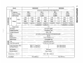
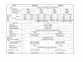
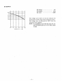
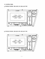
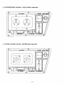
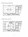
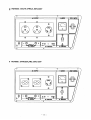
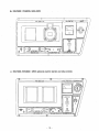
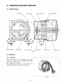
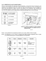
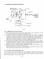
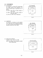
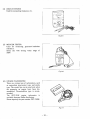
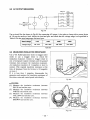
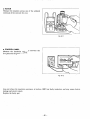
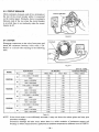
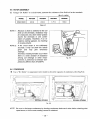
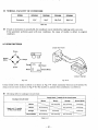
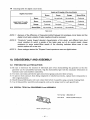
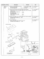
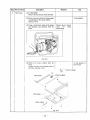
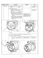
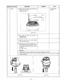
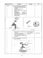
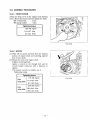
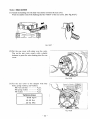
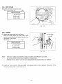
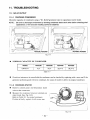
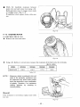
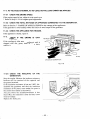
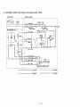
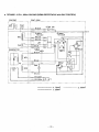
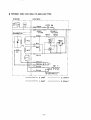
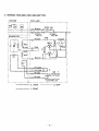
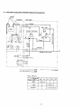
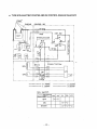
6
mEab
IISSUE EM D-GS08591
E
HRdi!!!I!@M
GASOLINE
ENGINE
GENERATQ
SERVICE MANUAL
@FUJl HEAVYINDUSTRIESLTD.
CONTENTS
Title
Section
1. SPECIFICATIONS
2.
PERFORMANCE
3.
FEATURES
4.
GENERAL
4-2
4-3
Location of Serial Number and Specification Number . . . . . . . ...”...............”..
Construction
21
5-2
Function . . . . . . . . . . . . . . . . . . . . .." . . . . . . . . . . . . . . . . .." . . .."" . . . . . . . . .." . . . . . . . . . . . . . . . . . . .
21
5-3
Description of Generator Operation . . . . . . . . . . . . . . . . . . . . . . . . . . . . . . . . . . . . . . . . . . . . . . . .
25
8.
MEASURING
. . . . . . . . . . . . . . .." . . . . . . .." . . . . . . . . . . . . . . . . . . . . . . . . . . . . . . . . . . . . .
28
. . . . . . . . . . . . . . . . . . . . . . . . . . . . . . . . . . .." . . . . . . . . . . . . . . . . . . . ..-
29
..".. ". . .." . . . . . . . . . . . . . . . . . . . . . . . . . . . . . . . . . . . . . . . . . . . . . .
32
8-1
Measuring Instruments . . . . . . . . . . . . . . . . . . . . . . . . . . . . . . . . . . . . . . . . . .. C. . . . . . . . . . . . . . . ..-
32
8-2
AC Output Measuring
8-3
Measuring Insulation Resistance . . . . . . . . . . . . . . . . . . . . . . . . . . . . . . . . . . . . . . . . . . . . . . . . ..-
35
CHECKING FUNCTIONAL MEMBERS
........ ......................................
Pilot
LamP
.
.
.
.
.
.
.
.
.
.
.
.
.
.
.
.
.
.
.
.
.
.
.
.
.
.
.
.
.
.
.
........ ....... ..............................
9-1
37
37
PRECAUTIONS
OF APPLICATIONS
PROCEDURES
. . . . . . . . . . .." . . . . . . . . . . . . . . . . . . . . . . . . . . . . . . . . . . . . . ..". "........
35
9-2
AC Receptacles
. . . . . . . . . . . . . . . . . . . . . . . . . . . . . . . . . . . . . . . . . . . . . . . ... . . . . . . . . . . . . . . . . . . . .
37
9-3
Circuit Breaker . . . . . . . . . . . . . . . . . . . . . . . . . . . . . . . . . . . . . . . . . . . . . . . . . . . . . . . . . . . . . . . . . . . . . . .
38
9-4
Stator . . . . . . . . . . . . . . . . . . . . . . . . . . . . . . . . . . . . . . . . . . . . . . . . . . . . . . . . . . . . .. C. . . . . . . . . . . . . . . . . .
38
9-5
Rotor . . . . . . . . . . . . . . . . . . . . . . . . . . . . . . . . . . . . . . . . . . . . . . . . . . . . . . . . . . . . . . . . . . . . . .. C. . . . . . . . .
39
9-6
Condenser
39
9-7
............................. ............... ...............................
Diode Rectifier . . . . . . . . . . . . . . . . . . . . . . . . . . . . . . . . . . . . . . . . . . . . . . . . . . . . . . . . . . . . . . . . . . . . . . .
Disassembly
AND ASSEMBLY
40
. . . . . . . . . . . . . . . . . . . . . . . . . . . . . . . .. C. . . . . . . . . . . . . . . . . .
41
10-1
Preparation and Precautions . . . . . . . . . . .."... ".. ".. ". . . . . . . . . . . . . . . . . . . . . . . . . . . . . . . .
41
10-2
Special Tools for Disassembly and Assembly . . . . . . . . . . . . . . . . . . . . . . . . . . . . . . . . . . . . .
41
10-3
Disassembly Procedures . . . . . . . . . . . . . . . . . . . . . . . . . . . . . . . . . . . . . . . . . . . . . . . . . . . . . . . . . . . .
42
10-4
Assembly Procedures .." . . . . . . . . . . . . . . . . . . . . . . . . . . . . . . . . . . . . . . . . . . . . . . . . . . . . . . . . . . . .
51
10-5
Checking, Disassembly and Reassembly of the Control Box . . . . . . . . . . . . . . . ..--..
58
Troubleshooting
11-1
NOTE:
21
Construction . . . . . . . . .." . . . .."... ". . . . . . .." . . ..". . . . . .." . . . . . . . . . .." . . . . . . . . . . . . . . . . . .
RANGE
12.
AND FUNCTION . . . . . . .."... ".- . . . . . . . . . . . . ..-. -C.---... -"---------
20
5-1
7.
11.
1
3
DESCRIPTION
SAFETY
10.
. . . .." . . . . . . . . . .."... ". . ..".. "... ". . . . . . . . . . . . . . . . . . . . . . . . ..."
. . . . . . . . . . . . . . . . . . .." . . . . .." . . .."... "". ". . . . . . . . . . . . . . . . . . . . . . . . . . . . .." . . . . . . . . . . . 5
6.
9.
. . . . . . . . . .." . . ..". """ . . . . . ..".. "" . . . . . . . . . . . . . . . . . . . . . . .." . . .."" . . . . . . . . .
CURVES
OF THE GENERATOR
. ..-”” .”... -. . ..”. o. . . . . . ..”......
6
External View of Generator . . . . . . . . . . . . . . . . . . . . . . . . . . . . . . . . . . . . . . . . . . . . . . . . . . . . . . . . . . . 6
Control Panel . . . . . . . . . . . . . . . . . . . . . . . . . . . . . . . . . . . . . . . . . . . . . . . . . . . . . . . . . . . . . . . . . . . . . . . . . . 7
4-1
5.
Page
. . . . . .." . . . . . . .." . . . . . . . . . . . . . . . . . . . . . . . . . . . . . . . . . . . . . . . . . . . . . . . . . .
59
11-2
No AC Output . . . . . . . . . . . . . . . . . . . . . . . . . . . . . . . . . . . . . . . . . . . . . . . . . . . . . . . . . . . . . . . . . . . . . . . . 59
AC voltage is too high or too low . . . . . . . . . . . . . . . . . . . . . . . . . . . . . . . . . . . . . . . . . . . . . . . . . . . ’61
11-3
AC voltage is normal at no-load, but the load cannot be applied ..-. ---... ”...-”.
62
11-4
No DC Output . . . . . . . . . . . . . . . . . . . . . . . . . . . . . . . . . . . . . . . . . . . . . . . . . . . . . . . . . . . . . . . . . . . . . . . .
63
11-5
idle Control . . . . . . . . . . . . . . . . . . . . . . . . . . . . . . . . . . . . . . . . . . . . . . . . . . . . . . . . . . . . . . . . . . . . . . . . ..-
64
......................................................................
67
WIRING DIAGRAM
As for the servicing information on engine portion, please
EHI 7, EH25
and EH34 engine service manual.
refer to the
I
1. SPECIFICATIONS
!
I
I
3V
I
I
UOlVNU3llV
I
i
I
I
r
I
T
i
i
j
a,
a
D
C
a
c
U
8
c
i
- 1 -
I
T
3NIDN3
N N
IoIo
IncD
-m
.-C
U
! I
I
I
-r
-
L
E
E
0
a3
X
w
d
a,
X
m
In
d
(D
I
(D
0
0
0
>
0
PC
0
0
0
9
0
-I
.
,
.
IS
:d
:
:
T
i
C
a,
U
S
s
I
!
I
j
:
!
I
I
!
I
E
E
m
b
b
X
d
m
0
X
m
0
d
I
i
N
-
I
I
i
j
!
I
U
n3
I
a,
n
I
.
:
0
.c
co
0
N
m
0
I
.
:
.
s
I
I
tlOlVNtl3llV
3N13N3
I
I
i
i
7
!
- 2 -
2. PERFOMANCECURVES
63T \
250
(1 25)
23ov/115v
220
/2 0
1
Rated
414
Load
50Hz
(Hz)
Hz
51
00
24ov/12ov
250
(1 25)
230V/115V
220
21 0
(1 0 5 )
0
112
Rated
Load
-3-
414
DC OUTPUT
DC Voltage
DCAmpere
DCoutput
........................
........................
........................
12v
8.3A
1oow
Thevoltagecurveshown
in theleftindicatesthe
characteristic of DC output when charging
a battery.
The voltagemay bedecreased by 20% whenthe
resistance load is applied.
NOTE: It is possible to use both DC and AC outputs simultaneously up to the rated output
in total.
C U R R E N T (AI&
- 4 -
3. FEATURES
3-1 BRUSHLESS ALTERNATOR
Newly developed brushless alternator eliminates troublesome brush maintenance.
3-2 CONDENSER TYPE VOLTAGE REGULATOR
A trouble freecondensertypevoltageregulatorensuresastablevoltage
underall
working
conditions.
3-3 OIL SENSOR
Oil sensor automatically shutsoff the engine whenever the oil level falls down below the lower limit
to protect the engine from seizure.
3-4 QUIET OPERATION
Robin RGV series generator delivers a quiet operation with:
0 A large super silent muffler.
0 A quiet 4-stroke Robin Rro OHV engine.
0 A silent cyclone air cleaner.
3-5 NO RADIO NOISE
Noise suppressor spark plug and spark plug cap are equipped standard
interfe.rence.
to prevent radio frequency
3-6 LARGE FUEL TANK
The large fuel tank allows more than 5 to 11 hours of continuous operation which is sufficient for a
half day or one day work without refueling.
3-7 RUGGED TUBULAR FRAME
Full cradle type rugged tubuler frame protects the generator all around.
3-8 COMPACT AND LIGHT WEIGHT
Newly developed brushless alternator enabled the
light in weight.
RGV generators to be very compact in size and
3-9 MINIMAL MAINTENANCE
0
0
0
0
0
0
A brushless alternator release the operator from periodical brush maintenance.
A trouble free condenser type voltage regulator.
A drip-proof alternator design.
No-fuse circuit breakers.
An electronic pointless ignition system.
A dust-proof cyclone air cleaner.
3-10 LONG-LIFE DURABILITY
The heavy-dut! 4 stroke Robin Rro OHV engine and virtually maintenance-free brushless alternator
ensure greater durability with :
0 A brushless alternator with a condenser voltage regulator.
Full rubber mount in a sturdy tubular frame.
0 A forged ste.el crankshaft supported by two main ball bearings.
A pointless electronic ignition system.
0 A cast-iron cylinder liner.
0 A forged aluminum connecting rod.
- 5 -
4. GENERAL DESCRIPTION OF THE GENERATOR
4-1 EXTERNAL VIEW of GENERATOR
GAUGELEVEL FUEL
VOLT?JETER
STOP B U T O N
CHOKE KNOB
kC
AIR CLEANER
.
.
DC
RECOIL STARTER
,
DC CIRCUIT BREAKEFi
OIL SENSOR
AC CIRCUIT
BREAKER
SPARK
MUFFLER
31L DRAIN PLUG
LEVEL
OIL
GAUGE
-6-
4-2 CONTROL PANEL
RGV2200, RGV2600 : SOHz, 60HZ-1lOV, 60Hz-120VTYPE
RGV2200, RGV2600 : 50H~-220V,240V, 60HZ-220V TYPE
-7-
RGV2200, RGV2600 : SOHZ, 60H~-lIOV/220VDUAL VOLTAGE TYPE
RGV2200, RGV2600, RGV4000 : U.K., 50H~-110V/120V[BS RECEPTACLE]
-8-
RGV2600 : U.S.A., 60Hz-120V [NEMA RECEPTACLE]
RGV2200, RGV2600, RGV4000 : GERMANY, 50Hz-220V
- 9 -
RGV2200, RGV2600, RGV4000 : SOUTH AFRICA, 50HZ-220V
I
RGV2200, RGV2600, RGV4000 SWITZERLAND, 50HZ-22OV
- 10 -
RGV2200, RGV2600, RGV4000 : AUSTRALIA, 50HZ-240V
RGV4000 : 5OHZ, 60Hz-11OV, 60HZ-120V TYPE
- 11 -
RGV4000 : 50H~-220V,240V, 60HZ-220V TYPE
0
RGV4000 : SOHZ, 6OHZ-l10V/220V TYPE
-
12 -
RGV4000 : U.S.A., 60H~-120V/240V [NEMA RECEPTACLE]
@
.
I
RGV2200, RGV2600, RGV4000 : FRANCE, 50Hz-220V
PRISES CA
L
CHARGE DE B A T T E R I E SEULEMENT
-
13-
0
RGV6000 : 50Hz, 60Hz-1lOV, 60Hz-IiOV TYPE
U
VMEIER
I
@
1
0
I
1
!
L
!
RGV6000 : 50H~-220V,240V, 60Hz-220V TYPE
f0
0
o\
0
~
O
\
0
0 )
- 14-
RGV6000 : 50Hz, 60H~-llOV/220VDUAL VOLTAGE TYPE
- 15 -
. .
RGV6000 : U.S.A., 60H~-120V/240V [NEMA RECEPTACLE]
RGV6000 : GERMANY, 50Hz-220V
f0
0
0
I
O
\
0
- 16 -
RGV6000 : SOUTH AFRICA, 50Hz-220V
J
h
A
U
U
,
k
E
m
I
VMEtER
I
63
0
RGV6000 : SWITZERLAND, 50Hz-220V
f0
o\
0
0
ON
0
- 17
-
E
RGV6000 : AUSTRALIA, 50HZ-240V
0
RGV4000, RGV6000 : (With optional electric starter and idle control)
-
la
-
RGV6000 : FRANCE, 5 0 H ~ 2 2 0 V
VOLTMETRE
0
0
RGV4000, RGV6000 : (With optional electric starter and idle control)
/@
P R l S E S CA
-
19 -
4-3 LOCATION of SERIAL NUMBER and SPECIFICATION NUMBER
Serial number and specification number are stamped on the LABEL (MODEL NAME) stuck on the end
cover.
NOTE: Always specify these numbers when inquiring about the generator or ordering spare parts in
order to get correct parts and accurate
service.
MODEL NAME
-
20 -
5. CONSTRUCTION AND FUNCTION
5-1 CONSTRUCTION
E N D COVER
MOUNT R U B B E R
STATOR BOLT
R E A R COVER
ROTOR COMPLETE
BALL BEARING
T H R O U G H BOLT
SUPPORT
STATOR COMPLETE
RING
FRONT C O V E R
Fig. 5-7
5-2 FUNCTION
5-2-1 STATOR
I
Thestatorconsists
of alaminatedsiliconsteel
sheet core, a main coil and a condenser coil which
are wound in the core slots.
excites
Thecoil
condenser
coil
field
the rotor
which generates AC voltage in the main coil.
i
-II
i
1
I
I
Fig. 5-2
- 21
-
5-2-2 CONDENSER
One or two condensers are installed in the control
box and are connected to the condenser coil of the
stator.
Thesecondensersandcondenser
coilregulatethe
output voltage.
:
5-2-3 ROTOR
The rotor consists of alaminatedsiliconsteel
sheet core and a field coil which is xound over the
core.
DC current in the fie.ld coil magnetizes the steel
sheet core. Tw~opermanent magnets are provided
for the primary exciting action.
Fig. 5-4
A diode rectifier and surge absorber is mounted insideof the insulator.
!
1
!
.
-
22 -
5-2-4 DC CIRCUIT BREAKER
j
(1) The 10 ampere DC circuit breaker mounted on
thecontrolpanelprotectswhole
DC circuit
fromgettingdamage
by overloadorshort
circuit.
Fig. 5-6
5-2-5 NO-FUSE BREAKER
The no-fuse breaker protects the generator from getting damage
by overloading or short circuit'in the
appliance.Table 5-1 shows the capacity of no-fuse breaker by each spec. and their objectof protection.
I
1
MODEL
RGV2200
I
SPECIFICATION
NO-FUSE BREAKER
50HZ-11OV
12A
Total output amperage
60Hz-11OV, 120v
15A
Total output amperage
50HZ-11OVI22OV
60HZ-120VI240V
I
'
6.5A (2-Pole, 2-Element)
(2-Pole.
8A 2-Element)
I
50HZ-11OV.
.
OV. 12Ov
. .
60HZ-240V
.
.
50HZ-11
OVl220V
i
60Hz-11OVi22OV,
12OVi24OV
50HZ-11OV
60142-1lov, 120v
I
.
15A
RGV4000
.
RGV6000
.
Total output amperage
Total output amperage
.
50Hz-220V
!
27A
j
30A
.
I
I
14A
(2-Pole,
2-Element)
[
15A
(2-Pole,
2-Element)
40A
!
50HZ-240V
50HZ- 11OV/22OV.
60HZ- 11OVi22OV.
60Hz-120Vi240V
.
Total amperage
output
1
Total output
amperage
amperage
Total output
Total output amperage
Total output amperage
Total output
amperaqe
1
Total outputamperage
Total output
amperage
20A
Total output amperage
30A
23 -
amperage
Total output
Output from30A receptacle
18A
Table 5-1
!
i
30A
20A
(2-Pole.
2-Element)
-
amperage
Total output amperage
.12A
-5OHZ-240V
50HZ-11
OVi220V
Total output
Total output
amperage
14A
50HZ-220V. 60Hz-220V
I
aA
I
I
50HZ-11OV
60HZ-11OV. 120V
I
.
1 OA (2-Pole. 2-Element)
I
.60Hz-11OV!22OV.
120V!240V
I
Total output amperage
. !i
9A (2-Pole.
2-Element)
I
60HZ-220V
!
Total output amperage
9A
RGV2600
Total output
amperage
18A
1OA
I
'
20A 60HZ-11
50Hz-220V
.
I
Total output amperage
8A
60HZ-220V
I
I
OBJECT of PROTECTION
6.5A 50HZ-220V, 240V Total output amperage
'
~
j
I
Total
amperage
output
Total output
amperage
ifrom Output
30A receptacle
60HZ-220
5-2-6 RECEPTACLE and AC PLUG (STD.SPEC.)
These are used for taking AC output power from the generator. A total of five kinds of receptacles, each
varying in rated voltage and current from another, are used. Each model has at least one receptacle to
delivertheratedgeneratoroutput.
As many AC plugsasthereceptacles,eachmatchingthe
corresponding receptacle, are provided. Table 5-2 shows the rated current for each receptacle. Be careful
not to use the receptacles andAC plugs beyond the specified amperage limitsto prevent burning.
I
I
up to 30 amperes
(See Caution.)
I
I
Table 5-2
Caution: To connect the appliance to locking receptacle,
insertthe plug intothe receptacle and turn it
clockwise to lock.
Fig. 5-7
NOTE: If your generator has receptacles peculiar to your country, Table
5-2 does not apply.
NOTE: The generator for U.S.A. market is equipped with NEMA standard receptacles shown in table
5-3. Use the proper plug for connecting appliance to the generator.
Style
Ampere
Receptacle
AC plug
125V
20A
NEMA
NEMA
5-20R
5-20P
NEMA
L14-20R
L14-20P
NEMA
NEMA
L5-30P
Table 5-3
-
24
-
Description
GFCl
(Ground Fault Circuit
Interrupter)
Receptacle, duplex
Locking Receptacle
Locking
Receptacle
5-3 DESCRIPTION Of GENERATOR OPERATION
PERMANENT MAGNET
FOR INITIAL EXCITATION
STATOR
COIL
MAIN
.
RECEPTACLE
SURGE
ABSORBER
"'_I
Fig. 5-8
5-3-1 GENERATION Of NO-LOAD VOLTAGE
When the generator starts running, the permanent magnet built-in to the
rotor generates 3 to 6V of
AC voltage in the main coil and condenser coil woundon the stator.
As one or two condensers are connected to the condenser coil, the small voltage at the condenser
which flows through the condenser coil. At this time: a small flux
coil generates a minute current
isproducedwithwhichthemagneticforce
at therotor's magnetic pole is intensified.Whenthis
magnetic force is intensified, the respective voltages in the main coil and condenser coil rise up.
As the current
increases, the magnetic flux at the rotor's magnetic pole increases further. Thus the
voltages at the main coil and condmser coil keep rising by repeating this process.
As AC current flows through the condenser coil, the density
of magnetic flux in the rotor changes.
This change of magnetic flux induces AC voltage in the field coil, and the diode rectifier in the field
flows through the field coil and
coil circuit rectifies this AC voltage into DC. Thus a DC current (8
magnetizes the rotor core to generate an output voltage in the main coil.
When generator speed reaches 2700 to 2800 rpm (50Hz type) or 3000 to 3300 rpm (60Hz type), the
current in the condenser coil and field coil increases rapidly.
This acts to stabilize the output voltage of each coils. If gene.rator speed further increases to the rated
value, the generator output voltage will reach to the rated value.
!z
:s
5-3-2 VOLTAGE FLUCTUATIONS UNDER LOAD
When the output current :g
flows through the main coil to the appliance, a magnetic flux is produced and
serves to increase current
in the condenser coil. When current
8
3 increases, the density of magnetic
flux across the rotorcorerises.
As a result,thecurrent
flowing in thefield -coilincreasesand
the
generator output voltage is preventedfrom decreasing.
z
;n
-
-
25 -
i
5-3-3 FULL POWER SWITCH (Dual Voltage Type)
The full power switch is provided for the dual voltage type
receptacle in each voltage.
to take out the full rated power from
one
1201240V
11OI220V)
r "-:(or
I
240V (or 220V)
43l
Fig. 5-9
MC,
-
I
Rec. 1
1
Fig. 5- 10
Switch :
Position I
ll0V
or
120v
1 10:'220v
or
120i240V
LOWER
VOLTAGE
RECEPTACLE
I
:
Rated
output
I
Half of rated
output
-
- 26 -
No output
can
be :aken.
Rated output
1
Table 5-4
"
HIGHER VOLTAGE
RECEPTACLE
:
I
I
1
Two main coils are wound over stator core. Each main coil outputs half the rated power at the
1owe.r
voltage (llOV or 120V). These main coils are
wound to be in the same phase. The full power switch
reconnects these main coilsin parallel or in series.
Fig. 5-9 shows a circuit diagram.When the full power switch is set for single lower voltage indication
(11OV or 12OV), the switch position is as indicated by the lower solid line in the diagram. Fig. 5-10 is a
simplified representation of this circuit, showing the two main coils connected in parallel.In this case, the
higher voltage -(220V or 240V) at Rec. 3 cannot be taken out. Rec. 2 for the lower voltage can output up
to the rated power (up to 30A if the rated current is over 30A), and Rec. 1 can output up toa total of 15A.
When the full power switch is set for double voltage indication (110V/220V or 120V/240V), the switch
position is as indicatedby the upper dotted line in Fig. 5-9. Fig. 5-11 is a simplified representation of this
circuit, showing the two main coils connectea in series. In this case, power can be taken simultaneously
from the receptacles for the both voltages. Rec. 3 for the higher voltage can output up to the rated power,
but Rec. 1 and Rec. 2 for the lower voltage can output only up tohalf the rated power each.
Table 5-4 is a summary of the above explanation. Select the proper output voltageby full power switch in
accordance with the appliance to be used.
5-3-4 VOLTAGE CHANGEOVER SWITCH
The generator of 50Hz 110V/220Vdualvoltagetypefor
U.K. isprovidedwithvoltagechangeover
switch instead of full power switch.
The output voltage is selected from llOV and 220V by turning this switch and both voltages cannot be
taken out simultaneously.
VOLTAGE
CHANGEOVER
SWITCH
11ov
RECEPTACLE
PTACLE
-
-
Fig. 5-12
-
27
-
6. SAFETY PRECAUTIONS
1. Use extreme caution near fuel. A constant danger
of explosion or fireexists.
Do not fill the fuel tank while the engine is running. Do not smoke or use opern flame near the fuel
tank. Be careful not to spill fuel when refueling. If spilt, wipe it and let dry before starting the engine.
2. Do not place inflammable materials nearthe generator.
Be careful not to put fuel, matches, gunpowder, oily cloth, straw, and any other inflammables near the
generator.
3. Do not operate the generator in a room,cave or tunnel. Always operate in a well-ventilated area.
Otherwise the engine may overheat and also, the poisonous carbon monoxide containedin the exhaust
gases will endanger human lives. Keep the generator at least
1 m (4 feet) away from structures or
facilities during use.
4. Operate the generator on a level surface.
If the generator is tilted or moved during use, there is a danger of fuel spillage and a chance that the
generator may tip over.
5. Do not operate with wet hands or in the rain.
Severe electric shock may occur. If the generator is wet by rain or snow, wipe it and thoroughly dry it
before starting.
Don't pour water over the generator directlynor wash it with water.
If the generator is wet with water, the insulations will be adversely affected and may cause current
leakage and electric shock.
6. Do not connect the generator to-the commercial power lines.
This may cause a short-circuit or damage to the generator.Use a transfer switch for connecting
with
indoor wiring.
NOTE: The parts numbers of
shown in Table6-1.
the transfer switches and of the plastic box to store them are as
!
Part No.
j
!
,
340-45606-08 j
367-43008-08
'
Q'ty
Transfer Switch
365-45604-08
367-45605-08
Part Name
I
I
348-43009-08 j
Transfer
Switch
I
I
!
'
Phase
Allowable Current
1
1
15A
1
1
30A
Transfer
Switch
1
Plastic Box
1
Plastic Box
1
j
1
1
'
i
1
j
i
60A
30A
60A
Table 6-7
7. Be sure to check and remedy the cause of circuit breaker tripping before re-setting it on.
CAUTION :If the circuit breaker tripped off as a result of using an electrical appliance,the cause
can be an overload or a short-circuit. In such a case, stop operation immediately and carefully
check the electrical applianceand AC plugs for faulty wiring.
-
28 -
7 . RANGE OF APPLICATIONS
Generally, the power rating of an electrical appliance indicates the amount of work that can be done by
it.The electric power required for operating an electrical appliance is
not always equaltotheoutput
wattage of the appliance. The electrical appliances generally have a label showing their rated voltage,
frequency, and power consumption (input wattage). The power consumption of an electrical appliance is
the power necessary for using it.When using a generator for operating an electrical appliance,the power
factor and starting wattage must be taken into consideration.
In order to determine the right size generator, it is necessary to add the total wattage of all appliances to
be connected to the unit.
Refer to the followings to calculate the power consumption of each appliance or equipmentby its type.
Incandescent lamp, heater, etc. with a power factor of 1.O
Total power consumption must be equal to or less than. the
rated output of the generator.
Example: A rated 3000W generator can turn thirty lOOW incandescent lamps on.
Fluorescent lamps,mercury lamps, etc. with a smaller power factor
Select a generator with a rated output equivalent to 1.2 to 2 times of the power consumption of the
load.
Example: A 400W mercury lamp requires 600W to 700W power source to be turned on.
A rated 3000W generator can power four or five 400W mercury lamps.
NOTE1: If
a power factor correction capacitor is not applied to the mercury lamp or fluorescent
lamp, the more powershall be required to drive those lamps.
A rated 3000 W generator candrive one ortwo 400 W mercury lamps without power factor
correction capacitors.
of the fluorscent lamp generally indicates the output wattage
of the
NOTE2: Nominal wattage
lamp.
Therefore, if the fluorescent lamp has no
special indication as to the power consumption,
efficiency shouldbe taken into accountas explained in Item (5) on the following page.
Motor driven tools and light electrical appliances
Generally the starting wattage of motor driven tools and light electrical appliances are 1.2 to 3 times
lager than their running wattage.
Example: A rated 250W electric drill requires a 400W generator to start it.
Initially loaded motor driven appliances such as water pumps,compressors,etc.
These appliances require large starting wattage which is 3 to 5 times of running wattage.
Example: A rated 900W compressor requires a 4500W generator to drive it.
NOTEi:
Motor-driven appliances require the aforementioned generator output only at the
starting.
Once their motors are started, the appliances consume about 1.2 to 2 times their rated
power consumption so that the excess power generated by the generator can be used
for other electrical appliances.
NOTE2
Motor-drivenappliancesmentioned
in ltems (3) and (4) vary in theirrequiredmotor
startingpowerdependingonthekind
of motor and start-upload. Ifitis
difficult to
determine the optimum generator capacity,select a generator with a larger capacity.
-
29 -
(5) Appliances without any indication as to power consumption
Some appliances have no indication as to power consumption;
butinsteadtheworkload(output)
indicated. In such a case, power consumption is to be worked out according to the numerical formula
mentioned below.
is
(Output of electrical appliance)
= (Power consumption)
(Efficiency)
Efficiencies of some electrical appliances are as follows:
Single-phase motor - - - - - - . . - - - - - - 0.6
0.75
0.65
0.9
Three-phase motor
-- --------Fluorescent lamp . . . . . . . . . . . . . . . . . . . 0.7 - 0.8
-
The smallerthe motor, the
lower the efficiency.
is 40W. Its efficiency is 0.7 and
accordingly, power consumption will be 40 + 0.7= 57W. As explained in Item(2), multiply
this power consumption value of 57W by 1.2 - 2 and you will get the figure of the necessary
capacity of a generator. In other words, a generator with a rated output
of 1000Wcapacity
can light nine to fourteen 40W fluorescent lamps.
Example 2: Generally speaking, a 400W motor means that its
work load is 400W. Efficiency of this
motor is 0.7 and power consumption will be 400 + 0.7= 570W. When this motor is used for
a motor-driven tool: the capacity of the generator should be multiple of 570W by 1.2 to 3 as
explained in the Itern(3).
570(W) X 1.2-3=684(W)-1710(W)
Example 1: A 40W fluorescent lamp means that its luminous output
I
MODEL
-
50HzFrequency
lncandesent lamp,
heater, etc.
Fluorescent lamp,
mercury lamp, etc.
i
1
1
14OOW
approx.
700W
60Hz
50Hz
60HZ
I
1800W
2000w
2200w
1
I
approx.
9OOW
approx.
approx.
400W ' 400W
Pump. compressor, etc.
approx.
300W
i
I
I
50Hz
!
60Hz
3000W
j
3500W
I
I
I
I
approx.
approx.
lOOOW j 1100W
I
I approx.
approx.
800W
I
1
I
!
I
Electric tool etc.
I
RGV2600
i
I
I
I
I
RGV6000
RGV2200
RGV4000
1I
approx.
approx.
approx.
approx.
approx.
approx.
400W
400W
1i
1
I
400W
Table 7-1
- 30 -
:i
1
50Hz
4400W
I
II
60Hz
4800W
I
approx.
2000W
1800W \
approx.
1600W
1!
approx.
approx.
16OOW
18OOW
750W
I
i
1
750W
'i
i
I
1
approx.
1500W
I
approx.
800W
1
800W
I
approx.
2350W
j approx.
I
2000W
1
app:ox.
800W
NOTES: Wiring between generator and electrical appliances
1. Allowable current of cable
Use a cable with an allowable current that is higher than the rated input current of
the load
(electrical appliance). If the input currentis higher than the allowable current of the
cable used, the
cable will become excessively heatedand deteriorate the insulation, possibly burning.
it out.
Table 7-2 shows cables and their allowable currents for your reference.
2. Cablelength
If a long cable is used, a voltage drop occurs 'due to the increased resistance in the conductors
decreasing the input voltage tothe load (electrical product). As a result, the load be
candamaged.
Table 7-2shows voltage drops per100 meters of cable.
TI
Nominal cross
I
mm2
No.
1
No. l m m
Qil00m
1
3010.18
2.477
2.5V
12
16
50 / 0.18
1.486
1.5V
5V
17
i
3710.26
0.952
A
I
0.75
7
18
1.27
2.0
8
13
i
I
Resistance
dia.
11I I1
Flowing Current
1A
5.5
1
12-10
10-8
I
0.517
45 10.32
23
5A
8A
10A
-
-
7.5V
12V
15V
5V
8V
1
1OV
4~
1
5~
,
12.5V
8V
1
I 1V
1
j
! 1 . 5 ~j 2.5V
I
3.5
3A
-
3V
I
25
70 10.32
0.332
I
,
I
-
1V
I
!
2V
I
I
I 2.5V 3.5V
Table 7-2
1
V = 100 X R X I X l
R means resistance ( 0 !lo0 m) on the above table.
Voltage drop indicates as
I
means electric current through the wire
(A).
8 means the length of the wire (m).
The length of wire indicates round length,it means twice the length from generator to electrical tools.
- 31 -
8. MEASURINGPROCEDURES
8-1 MEASURING INSTRUMENTS
8-1-1 “Dr. ROBIN” GENERATOR TESTER
The“Dr.Robin”generatortester
is exclusively
designedforfast,easydiagnosisandrepair
of.
Robin generators.
The “Dr. Robin” has the following features:
(1) Functions of voltmeter,
frequency
meter,
meggertester,capacitancemeterandcircuit
tester are combined in one unit.
(2) Fast and easy readout by- digital indicator.
(3) Built-in automaticbatterycheckerindicates
the time to change batterie.s.
(4) Tester and accessories
are
installed in a
handy, sturdy case for easy carring.
0
Fig. 8-1
SPECIFICATIONS
-
Model
I
Dr. Robin
~
Part Number
388-47565-08
0-5OOV AC
Voltage
Q)
p!
,
[r
25-70HZ
Frequency
m 1 Resistance
.G
-
0.1 -1.999 Q
L
3
m
10-1 00 ,E F
Condenser Capacity
m
a,
I
z
I
3M R
lnsuiation Resistance
_____
Circuit Protector
1
Power Source
I
I
Accessories
Dimensions (L X W
Fuse
2 x 6F44P(006P) Dry CellBattery
Testleadswith needie probes . . ‘ 1 set
Test leads with jack plugs . . . . . . 1 set
X
H)
i
285 mrnx200 r n m x l 1 0 rnrn
1.6kg
Weight
Table 8- 1
The “Dr. Robin”generator tester can
number.
be ordered from Robin generator distributors by the following part
I Dr. Robin Part Number : 388-47565-08 I
If you do not have a ”Dr. Robin“generator tester,use the instruments described in the following section
for checking generator parts.
-
32 -
8-1-2 INSTRUMENTS
(1) VOLTMETER
AC voltmeter is necessary.Theapproximate
ACvoltageranges
of the voltmeters to be
used forvarioustypes
of generatorsareas
follows:
0 to 15OV: Typewithanoutputvoltage
of
110 or 120V
0 to 300V: Type withanoutputvoltage
of
220,230 or 240V
0 to 15OV, 0 to 330V: Dual voltage type
-.
””-
I
F O R AC
Fig. 8-2
(2) AMMETER
ACammeter is necessary.AnACammeter
with a range. that can be changed according to
the current rating of a given generator is most
desirable. (About 10A, 20A, 100A)
FOR AC
Fig. 8-3
FREQUENCY METER
Frequency range : About 45 to 65Hz
!
NOTE: Be careful of the frequency meter’s
input voltage range.
.,
r
I
Fig. 8-4
-
33 -
(4)
CIRCUITTESTER
Used for measuring resistance, etc.
Fig. 8-5
TESTER
( 5 ) MEGGER
Used for
measuring
generator
insulation
resistance.
Select
one
with
testing
voltage range of
5OOV.
!
I
Fig. 8-6
(6) ENGINETACHOMETER
There are various types of tachometers, such
as contactlzss type,contacttype,andstrobe
type. The contact type can be used only when
the generator
and
engine
have
been
disassembled.Thecontactlesstype
is recommended.
The
PET-2100E
engine
tachometer
is
available from your Robin distributors.
Please inquireby the part number PET-2100E.
I
I
!
I
!
Fig. 8-7
-
34 -
8-2 AC OUTPUT MEASURING
TO AC RECEPTACLE
Fig. 8-8
Use a circuit like the shown in Fig.8-8 for measuringAC output. A hot plate or lamp with a power factor
of 1.0 may be used as a load. Adjust the load and rpm. and check that the voltage range is as specified in
Table 8-2 at the rated amperage and rated rpm.
Rated voltage
Voltage range
120v
110v
99-121V
220v
240V
21 6-264V 198-242V 108-1 32V
Table 8-2
8-3 MEASURING INSULATION RESISTANCE
Use a "Dr. Robin"generator tester in megger tester
mode or use
megger
a
tester
to
check
the
insulationresistance.Connectameggertesterto
one of receptacle. output terminals and the ground
terminal,thenmeasuretheinsulationresistance.
An insulation resistance of 1 megohm or more is
normal. (The original insulation resistance at the
time of shipment from the factory is 10 megohm
or more.)
If it is less than 1 megohm,disassemblethe
generator and measure the insulation resistance of
the stator, rotor and control panel individually.
0
STATOR
(1) Measure
the
insulation
resistance
between
BLUE lead and the core.
(2) Measure
the
insulation
resistance
between
WHITE lead and the core.
(3) Measure
the
insulation
resistance
between
YELLOW lead and -the core.
(4) lMeasure the
insulation
resistance
between
BROWN lead and the core.
Fig. 8-10
-
35 -
.
0
..
ROTOR
Measure the insulation across one of the soldered
terminals of the rotor and the core.
I
I
Fig. 8- 1 1
0
CONTROL PANEL
Measure theinsulationresistancesbetweenthe
live parts and the grounded parts.
Any part where the insulation resistance is less than 1MQ has faulty insulation, and may cause electric
leakage and electric shock.
Replace the faulty part.
-
36 -
9. CHECKING FUNCTIONAL MEMBERS
9-1 PILOT LAMP and VOLTMETER
Checkthepilotlampandthevoltmeter
if it is
turned on by applying specific voltage.
Pilot lamp and voltmetercannotbechecked
with
circuittesterbecauseitsresistanceistoolarge.
(See Fig.9-1.)
I
'
Fig. 9-1
Pilot lamp should be turnedon at 70 to 12OV.
9-2 AC RECEPTACLES
Using a "Dr. Robin"or a circuit tester, check continuity between the two terminals at the rear
of the AC
receptacles while the receptacle is mounted on the control panel. When continuity is found between the
output terminals of the rece.ptacle with a wire connected across these terminals,
the AC receptacle is
normal. When the wire is removed and no continuity is found between these terminals, the receptacles
are also normal.
&
.: I
.I:
Fig. 9-28
Fig. 9-2A
-
37 -
AC RECEPTACLE
I
9-3 CIRCUIT BREAKER
Check continuity between each of two terminals at
the rear of the circuit breaker while it is mounted
on the control panel. Normally, there is continuity
be.tween each of the two when the circuit breaker
is on while there is no continuity when the circuit
breaker is off. .
.
. .
.
Fig. 9-3
.
9-4 STATOR
Disengage connectors on the wires from stator and
checktheresistancebetweenwireswitha"Dr.
Robin" or a circuit tester refering to the following
table.
Fig. 9-4
(Rxl!! +lo%)
I
I
i
.
.
I
.
I
'
RGV2200
.
.
.
.
.
60
I
.
r;n
4"
'
.j
RGV6000 . .
.
.
..
r
.
i
120V, 120Vi240V
110V.
220V.
110Vj220V
I
.
::
60
. ! .
240V
!
1.24
1.24
1.24
1.24
1.oo
1.oo
120vi240v
120v.
~
.
i
0.33
!
I
0.39
0.24
Yellow iYellow
4.48
4.48.
0.75
. .
.
I
.
0.70
.
I
__
j
0.75
-
3.46.
Table 9-1
.
2.64
.
.
.!
1;99.
:
1.99
- !
1.
0.54
j
0.54
i
0.39
0.56
0.24
.
" .
!
.
-,
:
1.19
I
1:44
0.83
0.33
.
..
.
3.46
.
2.64
0.75
0.70
0.54
11ov. 220v. 11ovi220v
,
2.33
1.44
-
220v. 1lOV/220V
.
0.75
.
I
..
I
1.96
2.33
240V
50.
.
1.19
220v, 11OV:'220V
I
-1
OV/220V
240v
220v. 11OV!220V
-60 j
0.54 120V/240V
120V.
..
.
.I
0.83
'
1
.
jI
CondenserWinging
I
Black! Blue
1.96
1~ O VI . ~ O V ~ ~ ~ O V
11ov. 220v,
11
I
I
RGV4000
I
50
RGV2600
j
-
White / Red
OVl22OV
1.1
240V
220V,~
llOV/220V
!
60
iI
II
11ov,
220v,
50 I
. ,
AC Winding
Specification
Voltaae
I
Hz
1.03
I
' -1.03
0.79
0.79
0.24
.
.
.
.
-0.24
-0.56
:.
.
NOTE:- If--the--circuit
tester is not sufficiently accurate, it may not show the values given and may give
erroneous readings.
Erroneous readings will also occur when there
is a wide variation 0-f resistance among coil
at ambient temperatures different from
ZO"C(68"F).
windings or when measurement is performed
-
38 -
9-5 ROTOR ASSEMBLY
(1) Using a "Dr. Robin" or a circuit tester, measure the resistance of the field coil at the terminals.
(RxlQ &lo%)
MODEL
RESISTANCE
I
RGV2200
RGV2600
RGV4000
RGV6000
2.52 R
2.04 R
1.77R
1.60 R
I
Table 9-2
NOTE 1: Because a diode is soldered to the coil
ends at the terminals, resistance may
be measured only when tester probes
touche the terminalsinonecombinationofpolarity.Therefore,ifnoresistance reading appears, try checking
in reverse polarity.
NOTE 2: Ifthe circuit testerisnotsufficiently
accurate,itmaynotshowthevalues
given and may give
erroneous
readings.
Erroneous reading will also occur when
there is a wide variation of resistance
among coil windingsorwhenmeasurement is performed at embient temperatures different from2OoC(68"F).
9-6 CONDENSER
W
Use a "Dr. Robin" in capacitance meter mode to check the capacity of condensers. (See Fig.9-6).
3
RGV4000, RGV6000
I
Fig. 9-6
NOTE: Be sure to discharge condensers by shorting condenser leads each other before checking their
capacitance,or the accurate reading cannotbe obtained.
- 39 -
I
W
NORMALCAPACITY OF CONDENSER
MODEL
RGV2200
Resistance
RGV2600
17~F
.
RGV6000
202FX2
24kF
RGV4000
282FX2
Table 9-3
I
If such an instrument is unavailable, the condenser can be checked by replacing with a new one.
If thegeneratorperformsgoodwithnewcondenser,thecause
of trouble is defect in original
condenser.
.
- ..
9-7 DIODE RECTIFIER
DIODE RECTIFIER
Brown
Brown/
Orange
White
.
.
Brown
Brown
Brown
CIRCUIT TESTER
~.
Fig. 9-9
.
.
.
Fig. 9-10
..
Circuit -inside of the diode rectifiers is as shown in Fig. 9-9. Check continuity between each terminal
using a circuit tester as shown in Fig. 9-10. The rectifier is normal when condtinuity is as follows:
.
W
...
.
Checking table. for
.
analogue c.ircuit tester.
Analogue. circuit tester
Ii
I
I
I
b!
!
..
..
.
:
.
Apply
black
Brown
I
Brown
I
Apply red 3 .needle
-of ttie circuit tester
Brown
Orange
Brown;White
i
Sneedle of the
circuit
tester
Brown
Continuity
I
No continuity j
i
I
I
- 40 -
Brown:White
Continuity
.
.
N O continuity
Continuity
I
,
Continuity
No continuity
i
Orange
-
No continuity j
No continuity
r-"
No continuity
I
i
.
j
Continuity
?"-..,I
No continuity
W
Checking table for digital circuit tester.
Apply red @
J
needle of the circuit tester
Digital circuittester
Brown
Brown
Apply black@ needle
of the circuittester
-
Brown
Orange
1
N O continuity
!
Brown,White
Brown
Orange
BrownWhite
No continuity
No continuity
Continuity
No continuity
Continuity
1
Continuity
Continuity
No continuity
No continuity
Continuity
I
No continuity
Table 9-4-2
NOTE 1: Because of the difference of measuring method between the analogue circuit tester and the
digital circuit tester, polarityof tester needles should be reversed.
NOTE 2: “Continuity” means forward direction characteristics of
the diode, and different from short
circuit condition (in which apointerof
the testergoes out ofits normal scale),shows
resistanceto some extent. Whenresults of thecheckingindicatesfailureeveninone
section,replace with anew one.
NOTE 3: Some analogue testerslike “Simpson” brand operate assame as digital testers.
10. DISASSEMBLY AND ASSEMBLY
10-1 PREPARATION and PRECAUTIONS
1) Be sure to memorize the location of individual parts when disassembling the generator so that. the
generator can be reassembled correctly. Tag the disassembled part with the necessary information to
facilitate easier and smoother reassembly.
2) For more convenience,divide the parts into several groups and store them in boxes.
3) To prevent bolts and nuts from being misplaced or installed incorrectly, replace them temporarily to
their original position.
4) Handle disassembled parts with care; clean them before reassembly using a neutral cleaning fluid.
5 ) Use all disassembly .‘assembly tools properly, and use the proper tool for each specific job.
10-2 SPECIAL TOOLS for DISASSEMBLY and ASSEMBLY
Part Number : 388-95001-07
PartName
R E A R COVER PULLER
- 41
-
: REARCOVERPULLER
Step Part to remov
.
I
Description
..
Remarks
Tool
' .
-
Front Panel
..-
.
(1) Take off the four bolts and remove the
..
.
.
-
t
-1
.
-
~
10 mm spanner or
box wrench
front panel from the frame.
(See Fig. 10-1.)
.
(2) Disconnect the connectors on the wiring
beween the-front paneland the engine.
(SeeFig. 10-2.) . .
.
- . -
ti
~~
-
. .
..
.. .
. .
.- .
.."
.
,. - . ....
. .
. .
i
.
.
. .
Fig. 10-1
(.3) Take off the bushing from the bottom of
.. -
.
.
.-
the front panel.
(See Fig. 10-2.:)
.
.
.
Press the upperendof
the
bushing
and
pull
out:
.. .
. .
,.
..
f
:
:
!
(4)Disconnect the connectors on the wiring
from the front panel to'the alternator.
'(See Fig. 10-1.)
.
.
1
.
.
.
.-
I
i . .
..
-..
...
. .
- 42 -
. .
FIG. 10-3
.
. "
- . - :.
Step 'art to remove
FuelTank
2.
..
..
-
..
-Description
.
-1
Tool
..Remarks
-.
( I ) Discharge fuel from the tank: - .
Use
utmost
.care
about
1: Shut the fuel strainer.
.fire hazard. . 2. Remove the-strainercup.
3. Put a vessel to receive fuel under the - Wipe off spilt fuel
strainer and
open
the
-fuel.cock tothoroughly.
discharge fuel:(See Fig. 10-4.)
4. Attachthe strainer cup to the strainer
Donot lose the filter
body.
screen.
.
.
-
.
I
.. ..
. .
.
. .
.
:
;;
.
I
1;
Fig. 10-4
I
'
i
I
(2) Disconnect fuel hose from. the strainer.
Pliers
Loosenthe hose clamp on thetop of the
strainer and pull outthefuel
hose from
the strainer. (See Fig. 10-5.)
T
(3j Take off the four nuts and remove the
fuel tank. (See Fig. 10-6.1
I
Fig. 10-5
I
Fig. 10-6
-
43 -
10 mm spanner or
box wrench
Step Part to remove
3.
Muffler and
l4uffler
Cover
Description
!
Remarks
Tool
I
The rear plate is welded
to
the
frame of the
RGV6000.
10 mm spanner or
box wrench
( 1 ) Remove therear plate from the frame.
(Except for RGV6000)
6X 12mm flange bolt . . . . . . . . . . 2 pcs.
(2) Remove the two bolts whichfix the muffler to the alternator.
Loosen the two nuts on the muffler flange and remove the muffler
from the engine.
8X20mm bolt and washer ass'y . . . . . 2 pcs.
8mm stainless nut . . . . . . . . . . . . . . . . 2 pcs.
8mm spring washer
for RGV4000 and RGV6000 . . . . . . . 2 pcs.
Muffler gasket . . . . . . . . . . . . . . . . . . 1 PC.
12 mm spanner or
box wrench
(3) Remove the muffler cover 1 and the muffler cover 2 from the muffler.
6X lOmm bolt and washer ass'y - . 8 pcs.
(See Fig. 10-8.)
10 mm spanner or
box wrench
( 3 ) For RGV6000 only:
12 mm spanner or
box wrench
Remove the muffler bracket from the rear cover.
8X20mm bolt and washer ass'y . . . 2 pcs.
~cIUFFLERCOVER 1
A
M.ilL!FFLERCOVER 2
FAUFFLER BRACKET
for RGV6000 only
FIG. 10-7
- 44
-
Dart to remove
Pipe Frame
Remarks
Description
Tool
(1) For RGV6000:
Remove the fuel strainer from the frame.
(2) Remove the nuts which are fixing engine
and alternator to the mount rubbers.
(See Fig. 10-8.)
12 rnm spanner
Remove the air cleaner
(3) Using a chain-block, sling up the engine
for
cover
and alternator anddismountfrom
theeasier
dismounting.
frame.
Fig. 10-8
( 3 ) Remove the mountrubbersfromthe
frame.
Loosen the n u t s on the bottom side of
the frame. (See Fig. 10-9.)
’
12 mm spanner or
box wrench
MOUNT RUBBER
,
0
Fig. 10-9
- 45 -
'art to remove
Rear Cover
-
Description
Remarks
Tool
10 mm spanner or
box wrench
(1) Remove the end cover. (See Fig. 10-10.)
64 bolt. . . . . . . . . . . . . . . . 4 p a .
(2) Take off the rear cover.
1. Removethe four boltswhichfasten
the rear cover to the front cover.
6 4 bolt. . . . . . . . . . . . . . . . . 4 PC-,
2. Use. a special tool"REAR COVER
PULLER" to removethe rear cover.
a) Insert the two screws of the special
toolintothethreadholesof
the
rear cover.
b)Apply the center bolt of the special
tool on the head of the through bolt.
c)Tighten the center boltto pull out
the rear cover.
10 mm spanner or
box wrench
Insert the two screws
sufficiently and evenly,
or the thread hole maybe
damaged at removing.
Fig. 10-10
Fig. 10-1 1
!
In the case that "RE.AR COLER PULLER''is unavailable, remove the
rear cover by the follow-ing instructions.
I
I
3 . Hit on the boss andlegsof
rear
cover with a plastichammerto
loosen.
Do not give a strong hit
; on the
boss or legs.
i
i
Fig. 10-12
Fig. 10-13
- 46 -
I
Box Lvrench
Plastichammer
Step
'art to remove
.
.
- .
.Description
-
-
Remarks
6.
Startor
~
stator to the rear cover.
(See Fig. 10-14.)
~
~
Tool . .~
10 mm socket
wrench
(1) Remove the four bolts which fasten the
~~~
.
I
I
I
I
~~~~~~~~~
6~ BOLT . . . . . . 4
pcs.
. .
0
6,
-.
.
SPRING WASHER
. . . . . . . . . 4 pcs.
Fig. 10-14
I
(2) Put a pieceof .lumber on the floor in. I
upright position.
(See Fig. 10-15.)
II
.
-
.
( 3 ) Hold the rear cover and stator upside
down with both hands.
(4) Down the rear cover and stator over a
lumber lightly hitting the bottom of rear I
cover to the top end of lumber to pull out I
I
the stator.
i
(See FIE. 10-16.)
I
~.
1
"[NOTES]
1. Apply fingers-to stator coil to keep the stator from dr-oppingon the floor.
2. Gently hit the bottom of rear cover to-.the top end of lumber several times until the stator
comes out loose:'
I
!
Fig. 10-16
Fig. 10-15
-
47 -
Step Part to remove
6.
I
Description
Tool
Remarks
(5) Take apart the support ring and
Stator
stator from rear cover.
SUPPORT R I N G
\
60 BOLT . . . . . . 4 pcs.
60 SPRING WASHER
.........
Q WASHER
....4
. 4 pcs.
pcs.
Fig. 10-1 7
-
-. .
..
Rotor
i1 i Take off the through Dolt.
.Apply a box nrench on the head of I
through bolt. HittheLvrench handle with 1
a hammercounter-clockwise to loosen. j
Fig. 10-18
- 48 -
Box lvrench
Plastic hammer
Step Dart to remove
Description
I
I.
Rotor
Remarks
Tool
(3) Use a bolt and oil as a tool for pulling
out rotorin the following procedures:
1. Pour engine oil into the center hole of
rotor shaft.
Fill with oilto the shaft end.
(See Fig. 10-19.)
2. Prepareaboltwiththefollowing
thread size:
RGV2200,2600. . . . . . . MIOXP1.25
RGV4000,6000.. . . . . .M12XP1.50
3. Apply a few turns of seal tape around
the tip of the bolt.
Fig. 10-19
Fig. 10-20
4. Screw~thebolt into the thread of the
rotor shaft.
5. Torque the bolt using a socket wrench
until the rotor comesoff loose.
* The hydraulic pressure inside the rotor
shafttakes apan therotorfromthe
engine shaft.
(4)
Wipe .off oil thoroughly from rotor shaft
and engine-PTO shaft.
I
Fig. 10-21
- 49
-
Do notstickoutyour
face over the rotor.
It may jump up on
separation.
Socket wrench
Step Part to remove
8.
Front Cover
Description
Remarks
(1) Remove the front cover.
Loosenthe four bolts and removethe
front cover.
86 bolt . . . . . . . . . . . . . . . . 4 PC-.
Fig. 10-22
-
-
50 -
Tool
12 mm Socket
wrench
10-4 ASSEMBLY PROCEDURES
10-4-1 FRONT COVER
Attach the front cover to the engine main bearing
cover. Match the faucet joint and tighten the bolts.
M8 X 18mm bolt. . . . . . 4 pcs.
M 8 spring washer . . . . . 4 pcs.
Tightening torque
120-1 40 kg-crn
11.8-13.7 N m
8.7-10.1 ft4bS
Fig. 10-23
10-4-2 ROTOR
(1) Wipe off oil, grease and dust from the tapered
portion of engine shaft and matching tapered
hole of rotor shaft.
(2) Mount the rotor to the engine shaft.
Tighten the through bolt.
Applyawrench
on thethroughboltandhit
wrenchhandleclockwisewitha
hammer to
tighten.
If an impact wrench is available, use it.
Tightening torque :
I
Tightening torque
IRGV I
11.3-1 3.2 Nom
RGV
4000,6000
22.5-24.5 Nom
I
2200.2600
I
115-135 kg-cm
Fig. 10-24
8.7-10.8 ft4bs
230-250 kgwn
16.6-1 9.5 ft*lbs
- 51 -
10-4-3 STATOR
1
(1) Put the stator in the rear cover setting the four
grooves on the side of stator with thread holes
of the rear cover.
Tighten the four bolts tentatively to check if
the grooves and thread holes are aligned
correctly. (See Fig.10-25.)
NOTE :Be careful not to give cuts to wires when
them
pulling
(2) Remove the four bolts.
i
60 BOLT . . . . . . 4 pcs.
e"---60 SPRING WASHER
/ . . . . . . . . . . . 4 pcs.
i
I
I
60 WASHER . . . . 4 pcs.
B
I
!
i
a
I
-
.
I
L
Fig. 10-25
(3) Apply the support ring between the rear cover and
Tap on the support ring evenly using an
aluminum bar and a hammer to press into the
rear cover. (See Fig.lO-26.)
(4)Join the stator to rear cover with four bolts,
washers and spring washers. (See Fig. 10-25.)
M6 bolt .......................
4 pcs.
M6 washer ....................
4 pcs.
M 6 spring washer ........... 4 pcs.
I
/
; ALUMINUM
I
80-1 00 k g w n
7.8-9.8 Nom
5.8L7.2 ft-lbs
NOTE: Tighten four boltsevenlytakingseveral
steps.
Fig. 10-26
The dimensions of the stator bolts are shown in
Table 10-1.
MODEL
'
RGV2200
,
RGV2600
RGV4000
I
'
Tab!e 70-7
- 52
-
65mm
2.56 inch
85mm
3.35
inch
I
1i
i
!
S
i!
15mm
0.59 inch
,
20mm
0.79 inch
j
d
M6x
,.o
M6
X
1.0
b.16
X
1.0
I
I
95 mm
3.74 inch
1
115mm
4.53 inch
:
RGV6000
l
'
;
I
2o mm
0.79 inch
40 mm
1.57 irxh
I
!
-1
10-4-4 REAR COVER
(1) Attach the bushing over the lead wire drawn out from the rear cover.
Press the smaller endof the bushing into the windowof the rear cover. (See Fig.10-27.)
Fig. 10-27
Puttherearcoverwithstatorover
the rotor.
Tap on the rearcoverevenlywithaplastic
hammer to press the rotor bearing into the rear
cover.
Fig. 10-28
Fix the rear cover to theadaptorwith
bolts, spring washers, and washers.
M 6 x 25 mm bolt .............. 4 pcs.
M6 spring washer ............. 4 pcs.
346 washer .....................
4 pcs.
four
50-60 kg-cm
4.9-5.9 Nom
3.6-4.3ft-lbs
Fig. 10-29
- 53 -
10-4-5 END COVER
Attach the end cover to the rear cover.
M 6 X 8mm flange bolt -----.---..
4 pcs.
40-60kg*cm
3.9-5.9N-m
2.9-4.3 ft-lbs
Fig. 10-30
r-
10-4-6 FRAME
(1) Attach the mount rubbers to the frame.
Insert the setting tongue of mount rubber into
the hole on the frame and tighten the nut from
the bottom of the frame.
M8 flange nut ...................... 4 pcs.
F R A M E UPPER
Tightening torque
120-1 40 kg-cm
1 1.8-1 3.7 Nom
8.7-1 0.8 ft*lbS
Fig. 10-31
NOTE : The mount rubbers are selected to reduce vibration most effectivelyby model.
Be sure to use the correct mount rubber for your generator.
Although mount rubbers have the
same appearance, their characteristicsare different.
(2) Attach the
5 mm terminal of the grounding wires (green.:pellow) to the unpainted thread hole of the
frame base plate using a 5 mm brass scrsLv.
- 54 -
(3) Install the engine and alternator assembly into the frame.
Put the engine and alternator assembly into the frame from the sideof it.
Tighten the nuts over the mountrubber bolts to fix.
Mgnuts ..........................
4 pcs.
I
Tightening
torque
120-1 40 k g w n
1
11.8-1.3.7 Nom
8.7-1 0.1 ftolbs
NOTE :Remove the air cleaner cover for easier installation.
NOTE : When tightening the nuts, slightly lift the engine and alternator assembly so that the weight is
not applied to the mount rubbers.
(4) Fasten the other earth cable with5 mm terminal
to the unpainted bolt hole on the frame.
(See Fig.10-32.)
EARTH CABLE
Fig. 10-32
( 5 ) Attach the rear plate frame.
(For RGV2200,2600,4000 only)
"6 x 10 m m bolt .............. 2 pcs.
Attach fuel tank mount rubbers to rear plates.
The nuts €or mount rubbers are welded to rear
plates.
I
Tightening
torque
40-60 kg-cm
REAR PLATE
I
I
3.9-5.9 N-rn
2.9-4.3 f?*lbs
.
.
.
Fig. 10-33
- 55 -
104-7 MUFFLER and MUFFLER COVER
(1) For RGV6000 only:
Attach the muffler bracket to therear cover. Tighten the boltstemporarily.
(2) Attach the muffler cover 1 and the muffler cover 2 to the muffler.
M6 X lOmm bolt and washer Ass'y - . - - - -8-pcs.
7.9-9.8 Nom
5.8-7.2
ft*lbs
(3) Put the muffler gasket to the engine.
(4) Attach the muffler with muffler coverto the engine and the rear cover.
P
:&
Tighten the two nuts fou the muffler first.
Use the spring washers €or RGV4000 and
RGV6000.
8mm stainless nut.................... 2 pcs.
8mm spring washer.. ................. 2 pcs.
(for RGV4000 and RGV6000 only)
220-280 k g w n
21.6-27.4 Nom
15.8-20.2 ft-lbs
:zTightentheboltstofixthe
A
muffler to the
rear cover.
M 8 X20mm bolt and washer Ass')'
.-.-.2 pcs. (for RGV2200, 2600, 4000)
190-250 kg-crn
18.6-24.5 Nom
13.7-1 8.0
ft*lbS
is For RGV6000 only:
Tightenthetwobolts
to fix the muffler
bracket to.the 'rear cover: and .then the two
-.. bolts-for the muffler to the
muffler bracket.
M 8 X 2 0 m m bolt and Lvasher Ass'y
- . ..... 3-pcs. (for
RGV6000
only)
190-250 kg-cm
18.6-24.5 Nom
13.7-1 8.0 ft*lbS
Fig. 10-35
- 56 -
rainer
fuel
( 5 ) For RGV2200, RGV2600 and RGV4000 only :
Attach the rear plate to the frame.
M6 X 1Omm bolt ............... 2 pcs.
I
Tightening
torque
40-60 kg-cm
I
3.9-5.9 Nom
2.9-4.3 ft*lbs
10-4-8 FUEL TANK
(1) For RGV2200, RGV2600 and RGV4000 only :
Attach the fuel strainer to the bottomof the fuel tank.
Screw in the fuel strainer all the way and return
one to two turns, andthen lock it with the lock nut.
FUEL GAUGE
For RGV6000 only :
theAttach
frame.
to the
TAXK FUEL
CAP
4.9-6.9 Nom
(2) Mount the fuel tank on the frame with rubber
washers between the tank flange and the frame.
M6 X20mm bolt (black) ...........
Rubber \%-asher........................
NOTE : For easy tank assembly,
glue the rubber /
;
.
washersover the mountingholes of the
Y
'
frame.
(3) Connect the rubber pipe.
First, €it thehose clamps on therubber pipe
and
connect
it to the
strainer
and
the
fasten
carburetor.
Then
the
it with
hose
clamps.
For RGV6000, connect the rubber pipe to the
strainer and the fuel tank in the same wag.
HOSE C U M P
easier connection.
-
57 -
Fig. 10-36
10-4-9 FRONT PANEL
-Mount the front panel assembly to the frame.
Refer to Section 10-5 for disassembly, checking and reassembly proceduresof the front panel.
(1) Connect the wires from the front panel and the
engine.
(2) Connect the wires drawn out from the stator to
the wires from the front panel.
NOTE :Connect the wires of the same color.
(3) Presstheupperend
of thebushingintothe
bottom window of the front panel.
(4) Mount the front panel to the frame.
M6 X 12 mm flange bolt ....................
4 pcs.
3.9-5.9 Nom
Fig. 10-37
10-5 CHECKING, DISASSEMBLY and REASSEMBLY of the FRONT PANEL
10-5-1 CHECKING OF THE FRONT PANEL
Dismount the front panel from frame.
Remove the controlpanel and check each components and wiring.
Refer to Section 9 for the detailof checking procedure for the componentsin the front panel.
10-5-2 DISASSEMBLY
(1) Remove the control panel from the front panel.
3 4 4 s c r e ~..............
~
6 pcs. (RGV2200, RGV2600, RGV4000)
344screLy .............. 7 pcs. (RGV6000)
(2) Disconnect-the connectorson the wires to detach the control panel and front panel.
(3) Remove the condensers and diode rectifierfrom the front panel.
(4) After disconnecting individual wires, remove the control panel components.
NOTE : Full power switch and pilot lamp have their wires soldered. Unsolder them to remove those
parts if necessary.
10-5-3 REASSEMBLY
(1) Install the receptacles, no-fuse breaker, terminals, switches, etc. on the control panel and wirz them.
NOTE : Circuit diagrams are shown in Section 12. Colored wires are used for easy identification, and
are of the correct capacity and size. Use heat-resistant type wires (permissible temperature
range 75°C or over) in the specified
gauge shown. in the circuit diagrams.
(2) Install condensers, and diode rectifier into the front panel.
(3) Connect the wires of control panel components and front panel.
(4)Attach the control panel to the front panel.
M4 screw ..... 6 pcs. (RGV2200, RGV2600, RGV4000)
M4 Screw .............. 7 pcs. (RGV6000)
1.2-1.5 Nom
- 58 -
11. TROUBLESHOOTING
11-1 NO AC
OUTPUT
11 -1-1 CHECKING CONDENSER
Check the capacity of condensers using a “Dr. Robin”generator tester
in capacitance meter mode.
NOTE : Be sure to discharge condensers byshorting condenser leads each otherbefore checking their
capacitance, or the accurate reading cannot be obtained.
Fig. 11-1
NORMAL CAPACITY OF CONDENSER
I
MODEL
’
CAPACITY
j
I
RGV2200
RGV2600
24y F
17.2F
I
RGV4000
1
RGV6000
20,2Fx2
i
28cFX2
!
I
Table 1 1 - 1
If such an instrument is unavailable,the condenser can be checked by replacing with a new one.If the
generator performs good with new condenser, the cause of trouble is defect in original condenser.
~.
11-1-2 CHECKING STATOR
Removecontrolpanelanddisconnectstator
wires at the connectors.
Measure the resistance between terminals
on
stator leads. (See F i g 1 1-2)
Refer to Table 9-1 for normal resistance.
If stator is faulty: replace it \vith a new one.
Fig. 1 1-2
-
59 -
!
Check
the
insulation
resistance
between
statorcoreandeachstatorleadusinga
Dr.
Robin generator tester in msgger tester mode
or a megger tester. (Fig. 11-3)
If insulation is bad, replace stator with a new
one.
Fig. 1 1-3
1
11-1-3 CHECKING ROTOR
!
(1) CHECKING FIELD COIL
W Remove rear cover and stator.
Fig. 1 1-4
W
Using a Dr. Robin or a circuit tester, measure the resistance of the field coil at the terminals.
t
MODEL
.
RESISTANCE
2.52 Q
.
I
2.01ST
( R X l Q *lo%)
'
RGV4000
'
1.77R
RGV6000
RGV2200
RGV2600
I
1.60 Q
T&de 1 1-2
NOTE 1 : Because a diode is soldered to the coil
ends at the terminals, resistance may
be measured only when tester probes
touch the terminals in one combination
of polarity. Therefore, if no resistance
reading
appears,
checking
try
in
reverse polarity.
[Remedy]
If the resistance is not normal, replace rotor with a
new one.
I
Fig. 1 1 -5
- 60 -
Measuretheinsulationacrossone
of the
soldered terminals of the rotor and the core.
(Fig. 11-6)
If insulation is bad, replace rotor with a new
one.
Fig. 1 1 -6
11-2 AC VOLTAGE IS TOO HIGH OR TOO LOW
11-2-1 CHECKING ENGINE SPEED
If the engine speed is too high or too low, adjust it
to the rated r.p.m.
.
..
;;
;
[How to adjust engine r.p.m.1
Loosen the lock nut on the adjusting screw.
Turntheadjustingscrewclockwise
to decreaseenginespeed or counter-clockwiseto
increase engine speed.
Normal engine speed at no load is :
3100 - 3150 r.p.m. for 50Hz type
3700 - 3750 r.p.m. for 6OHz type
11-2-2 CHECKING CONDENSER
Check condenser referring to Step 11-1-1
11-2-3 CHECKING STATOR
Fig. 1 1 -7
Check stator referring to Step 11-1-2.
11-2-4 CHECKING ROTOR
Check rotor referring to Step 11-1-3.
-
61 -
I
11-3 AC VOLTAGE
11-3-1 CHECK THE
IS NORMAL AT NO-LOAD, BUT THE LOAD CANNOT BE APPLIED.
ENGINE SPEED.
If the engine speed is low, adjust
it to the rated r.p.m.
* Refer to Step 11-2-1 for engine speed adjustment.
11-3-2 CHECK THE TOTAL WATTAGE OF APPLIANCES CONNECTED TO THE GENERATOR.
Refer to Section 7 "RANGE OF APPLICATIONS" for the wattage of the appliances.
If the generator is over-loaded, reduce the load to the rated outputof the generator.
11-3-3 CHECK THE APPLIANCE
FOR TROUBLE.
If the appliance is faulty, repair it.
11-34 CHECK IF THE
ENGINE
HEATED.
IS OVER-
If the cooling air inlet and/or cooling air outlet is
cloggedwithdirt,grass,chafforother
debris..
remove it.
AIR OUTLET (GENERATOR!
.
Fig. 11-8
..
11-3-5
CHECK
THE
INSULATION OF THE
GENERATOR.
Stop the engine. Measure the insulation resistance
between- theliveterminal
of thereceptacleand
the ground terminal.
If the insulation resistance is less than 1MQ: disassemble thegeneratorandcheck
the insulation
resistance of the stator, rotor and the live parts in
the control box. (Refer to Section 8-3.)
Any part where the insulationresistance is less
than 1 M E , the insulation is faulty and may cause
electric leakage.
Replace the faulty part.
Fig. 1 1-9
-
62 -
11-4 NO DC OUTPUT
11-4-1 CHECK THE AC OUTPUT.
Check the generator by following Step 11-1-1through Step 11-1-3.
114-2 CHECK THE DC BREAKER.
If the D C breakerturned off whilecharginga
battery,
check
the
cables
for
short-circuit
or
connection in reverse polarity before resettingit on.
NOTE : IftheDC
output is used to chargea
largecapacitybattery
or anover-dischargedbattery, an excessivecurrent
may flow causing.
11-4-3 CHECK THE
II
WIRING.
Fig. 17-10
Check all the wires to be connected correctly.
11-44 CHECK THE DIODE RECTIFIER.
Remove the control panel and che-ck the diode
rectifier with a circuit tester.
Refer to Section 9-7 "DIODE RECTIFIER'' for the
checking procedure.
11-4-5 CHECK THE DC COIL
Check the resistance between two brown leads from stator with a circuit tester.
I
I
I
MODEL
RGV2200
RGV2600
RGV4000
I
SPECIFICATION
i
i
i
!
60Hz
i
120V,220V, 11OV/22OV,12OVl24OV
1
I
120V.
220V,
110V/220V.
;
i
11 OV. 220V,240V. 11OV!220V
0.24R
120V.220V, 11OVi22OV,12OVl24OV
0.200
1 1
OV. 220V, 240V, 11OVi22OV
0.150
I
120V.220V. 11OVl22OV. 120V/240V
0.13R
50Hz
~
: 60Hz
:
:
50Hz
60Hz
5OHz
RGV6000
8
RESISTANCE
50Hz
60Hz
11OV. 220V.240V,
110V.
220V,
240V.
11OVl22OV
110V/220V
120Vi240V
I
0.3652
0.32R
1
0.260
1
0.21 0
Table 11-3
If the resistance reading is much larger or smaller than the specified value, the DC coil
faulty. Replace stator with a new one.
-
63 -
of the stator is
11-5 IDLE CONTROL (OPTIONAL EQUIPMENT)
11-5-1 ENGINE SPEED IS NOT INCREASED WHEN A LOAD IS APPLIED
(1) Inspect the solenoid bracket.
Check the bend angleof solenoid bracket.
If thebracketisdistorted,correcttheangle
with proper tool. .
(2) Checkthe
wattage of loadappied
to the
generator.
If the
generator
is
loaded
over
the
rated
wattage, the engine speed can not be increased.
lMost induction loads such as electric motor or
electric tools or welding machine require three
to five times large wattage
of their ratings at
starting.
This starting wattage must not exceed the rated
output of the generator.
v
(3) Check the slow set r.p.m.
The
normal
idling
speed
CONTROL is as follows :
by
the
Fig. 11-12
IDLE
ADJUSTING SCREW
RGV2200, 2600 - - - - 1900
- . - 2100 r.p.m.
.
- 2200 r.p.m.
RGV4000, 6000 - - - . -2000
Theabove
speedsettingis
for cold engine
condition.
If the engine speed is out of adjusting range of
the
adjusting
screw,
move
the
solenoid
backward.
Fig. 77-73
-
64 -
(4) Check the wiring through ZCT on the IDLE
CONTROL UNIT.
IDLE CONTROL UNIT
i
I
A) Single Voltage Type
Make sure that an output wire from main coil
is passingthrough
the. ZCT ontheIDLE
COKTROL UNIT.
B) Dual Voltage Type
Checkthattwooutputwires(blackwireand
red wire) from main coils are passing through
the ZCT on the IDLE COKTROL UKIT in the
same direction.
/
\\\
ZCT
Fig. 17-14
( 5 ) Checking the IDLE CONTROL UNIT
Checktheresistancebetweensixleads
of
IDLE CONTROL UNIT with circuit tester.
1-”
IDL
I
Terminal numberof
the IDLE CONTROL UNIT
Fig. 11-15-
Apply black 3 needle of the circuit tester
Circuit tester
(with battery power source1SV)
\I
n
L.
!
Apply
red
@ needle
of the circuit tester
!
Q
1
I
kR
3 1
I
1
I
250 kR
kR
.
250
22
00
250
1
.a
:g
75
kQ
A
i
75kQ
I
00
250
kR
I
,
”
.
:
f
.n
.&
I-
250 kR
I
8.5 kR
I
3 0 -
!
7.8kQ
7.8kR
75 kR
1
1
* Teste: measuring range : 1000 k 0
Tabi‘e 11-4
NOTE : The resistance readings vary depending on the types
of circuit testers.
of the resistance readingsmeasuredbyanordinary
Theabovetableshowsanexample
analogue circuit tester with 1.5 volt battery power source.
It is advisable for you to check the resistance readings using your standard circuit tester and
revise the checking table.
-
65 -
11-5-2 ENGINE SPEED IS NOT REDUCED WHEN LOAD IS OFF.
(1) Check the distortion of the SOLEKOID BRACKET as shownin step 11-5-1-(1).
(2) Check the wiring of SOLENOID.
Check two leads from SOLENOID are securely connected.
(3) Check the wiring of IDLE CONTROL USIT.
Check all leads from IDLE CONTROL UNIT are securely and correctly connected.
(4)Checking- the SOLEKOID.
Measure the resistance between two leads from
SOLENOID.
I
NORMAL RESISTANCE
SOLEXOID
\
I
25-31 O
If the resistance. is larger or smaller than
range, .SOLENOID
.
is defective,
Replace \vith a new one.
th-is
Fig. 11-17
.-
.
.
.
- 66
-
12. WIRING DIAGRAM
0
RGV2200,2600 : 50Hz-11OV, 60H~-11
OV, 60HZ-120V TYPE
r--------r""""""-ENGINE
CONT-BOX
~
1
ET
I
-
67 -
RGV2200,2600 : 50H~-220V,240V, 60Hz-220V TYPE
rENGINE
""""~
?@
..
.
rCONT-BOX
"""""""
1
.
I
.
,,
I
I
STOP SW
b
,
i
I
i
I
fix:
TCB
I
L"
- 68 -
RGV2200,2600 : 50Hz, 60H~-llOV/22OVTYPE
r-------- r"""""-"""
ENGINE
CONT-BOX
1
~
ET
1. 25mm2
- 69
-
RGV2200,2600 : U.K., 50H~-llOV/22OV[BS RECEPTACLE]
ENGINE
r””“”~
CONT-BOX
r”””””“””I
1
I
“ - 3
Black
STOP SW
I
c
CB
I
1
I
I
.
Brown/White
-
70 -
T
0
RGV2600 U.S.A.,60Hz-12OV [NEMA RECEPTACLE]
ENGINE
~
r""""""""CONT-BOX
1
I
I
ET
- 71 -
0
RGV4000 : 50H~-11
OV, 60Hz-11OV, 60Hz-120V-TYPE
ENGINE
CONT-BOX
r-------1r--
1
I
STOP SW
I
ET
! I Ii Piii
I
- 72 -
RGV4000 50H~-220V,240V, 60HZ-220V TYPE
ENGINE
CONT-BOX
7r--
1
ET
I
I
i
I
I
I
I
I
i
I
I
L
I
I
I
I
Brown/White
1 - L
-
73 -
I
-J
..
0
RGV4000 : 5OHZ, 6OHZ-l1OV/220V TYPE
ENGINE
CONT-BOX
r-------7r--
1
ET
- 74 -
RGV4000 : U.K.., 50H~-llOV/220V[BS RECEPTACLE]
ENGINE
CONT-BOX
- -- - -- r-------1 r---------1
I
Black
STOP SW
I Ii P Ii i
I
I
I
J
- 75
-
0
RGV4000 : U.S.A., 60Hz-l20V/240V [NEMA RECEPTACLE with IDLE CONTROL]
CONT-BOX
r"""-"""""""""-
ENGINE
r--
~
1
I
I
STOP SW
Green/
Yellow
!L""""II""""-"""""""""""---l
I
-
~
76
-
A ET
'I
RGV6000 : 5OHZ-1lOV, 6OHZ-1 lOV, 60Hz-120V TYPE
ENGINE-
r--
CONT-BOX
1 r---
1
I
I
STOP SW
I
ET
Brown/White
- - - -- - -- - - 0.75mm2
- 77
-
I
2.00mm2
RGV6000 : 50H~-220V,240V, 60HZ-22OV TYPE
rCONT-BOX
""""""""-
ENGINE
r""""7
1
I
I
I
ET
.
I
-
1
:
I
Brown/White
- - - -- - -- - - 0 .75mm2
2 . Omm"
1.25mm'
- 78 -
I
0
RGV6000 : 50Hz, 60HZ-11OV/22OV TYPE
ENGINE
rCONT-BOX
""""""""""
r--
1
I
I
STOP SW
?
I
I I
I
I
L--J
1
Green/
ET
Brown/White
- 79 -
-
I
RGV6000 : U.K., 50H~-lIOV/220V[BS RECEPTACLE]
ENGINE
rCONT-BOX
""""""""""
~
1
I
STOP SW
Green/Yellow
T
IL - - -- - -
GENERATOR
-I
ET
I
I
I
I
I
I
I
I
I
r--------
Trl
I
Brown/White
- 80
-
0
RGV6000 : U.S.A., 60Hz-l20V/240V [NEMA RECEPTACLE with IDLE CONTROL]
ENGINE
CONT-BOX
1r - -
r--
I
1
II
I
I
I
I
I'
I
White
I
I
J
-
81 -
a TYPE WITH ELECTRIC STARTER (Optional Equipment)
15mm2
,~
ENGINE
CONT-BOX
1;
-Black
I
!
4
ET
Green/Yellow
!
Key s w i t c h
OFF
ON
I
START
-
a2 -
I
ST
IG
6
-M
I
I
I
TYPE WITH ELECTRIC STARTER AND IDLE CONTROL (Optional Equipment)
ET
"""""""-""-"II
L - - -- - -
blue
!
Key s w i t c h
+M
-M
I
-
a3 -
B
IG
ST
0
TYPE WITH IDLE CONTROL (Optional Equipment)
ENGINE
rCONT-BOX
"""""""""""""
" " - ~
r
--, -
I
I
-"
I
I
1
,
"
"
Green/
Yellow
SOL
I
-
I
" I
I
.
I
CHG
- 84
-
Part Name
Symbols
MC
AC Winding
cc
Condenser Winding
DC
DC Winding
FC
Field Winding
Condenser
C
Diodes Stack
L
D
Pilot Lamp
DC
CB
Assy
Output
Terminal
T
Circuit Breaker
N FB No-Fuse Breaker
vc sw
Voltage Changeover Switch
sw1
Voltage Changeover Switch
STOP SW
0.s
so L
Engine Stop Switch
Oil Sensor Control Unit
Solenoid
Idle ControlUnit
Spark Plug
Charge Coil
Ignition Coil
ET
ST. M
KEY SW
BAT
V
REC
Earth Terminal (Ground Terminal)
Starting Motor
Key Switch
: Battery
Voltmeter
AC Output Receptacle
Control Box
-
(Front
85 -
Panel)
CONT.BOX
0 FUJI HEAVY -INDUSTRIESLTD.
INDUSTRIAL PRODUCTS DIV.
.:'.
Subaru Bldg.
1-7-2, Nishi-Shinjuku, Shinjuku-ku, Tokyo 160, Japan
TEL : (Tokyo 03) 3347-2414,5 TELEX 232-2401 FUJI J
CABLE ADDRESS: FUJIHEAVY TOKYO
FACSIMILE: (TOKYO 03)3347-2418
.
."
.-
.~
....
PRINTED IN JAPAN
June-1993
~
x\
.~
...
.
.. .
.
"