1
QB Series
Precision Balance
Operation Manual
42194
Contents
About This Manual ................................................................................................................................... 1
1.0
Introduction.................................................................................................................................. 1
1.1
1.2
1.3
1.4
1.5
1.6
1.7
1.8
2.0
Unpacking and Inspection . . . . . . . . . . . . . . . . . . . . . . . . . . . . . . . . . . . . . . . . . . . . . . . . . . . . . . . . .
General Care and Maintenance . . . . . . . . . . . . . . . . . . . . . . . . . . . . . . . . . . . . . . . . . . . . . . . . . . . . .
Installation Guidelines . . . . . . . . . . . . . . . . . . . . . . . . . . . . . . . . . . . . . . . . . . . . . . . . . . . . . . . . . . . .
Installation Steps . . . . . . . . . . . . . . . . . . . . . . . . . . . . . . . . . . . . . . . . . . . . . . . . . . . . . . . . . . . . . . . .
Special Information . . . . . . . . . . . . . . . . . . . . . . . . . . . . . . . . . . . . . . . . . . . . . . . . . . . . . . . . . . . . . .
Front Panel . . . . . . . . . . . . . . . . . . . . . . . . . . . . . . . . . . . . . . . . . . . . . . . . . . . . . . . . . . . . . . . . . . . .
Powering Up the QB Series Balance . . . . . . . . . . . . . . . . . . . . . . . . . . . . . . . . . . . . . . . . . . . . . . . . .
Powering Down the QB Series Balance . . . . . . . . . . . . . . . . . . . . . . . . . . . . . . . . . . . . . . . . . . . . . . .
1
2
2
3
4
4
5
5
Weighing Operations ................................................................................................................... 6
2.1
2.2
2.3
2.4
2.5
2.6
2.7
Units of Measure . . . . . . . . . . . . . . . . . . . . . . . . . . . . . . . . . . . . . . . . . . . . . . . . . . . . . . . . . . . . . . . .
Changing Units of Measure . . . . . . . . . . . . . . . . . . . . . . . . . . . . . . . . . . . . . . . . . . . . . . . . . . . . . . . .
General Weighing . . . . . . . . . . . . . . . . . . . . . . . . . . . . . . . . . . . . . . . . . . . . . . . . . . . . . . . . . . . . . . .
Weighing with a Tare . . . . . . . . . . . . . . . . . . . . . . . . . . . . . . . . . . . . . . . . . . . . . . . . . . . . . . . . . . . . .
Batching . . . . . . . . . . . . . . . . . . . . . . . . . . . . . . . . . . . . . . . . . . . . . . . . . . . . . . . . . . . . . . . . . . . . . .
Removing the Tare . . . . . . . . . . . . . . . . . . . . . . . . . . . . . . . . . . . . . . . . . . . . . . . . . . . . . . . . . . . . . .
Weighing with the Comparator Function . . . . . . . . . . . . . . . . . . . . . . . . . . . . . . . . . . . . . . . . . . . . . .
2.7.1
2.7.2
6
6
7
7
7
8
8
Comparator Function Activation . . . . . . . . . . . . . . . . . . . . . . . . . . . . . . . . . . . . . . . . . . . . . . . . . . . . . . 8
Basic Over/Under Parameter Selection . . . . . . . . . . . . . . . . . . . . . . . . . . . . . . . . . . . . . . . . . . . . . . . . . 9
2.8 Setting the Upper and Lower Comparison Limits. . . . . . . . . . . . . . . . . . . . . . . . . . . . . . . . . . . . . . . . 9
2.8.1
2.8.2
2.8.3
2.8.4
Reference Sample Method . . . . . . . . . . . . . . . . . . . . . . . . . . . . . . . . . . . . . . . . . . . . . . . . . . . . . . . . .
Digital Reference Method . . . . . . . . . . . . . . . . . . . . . . . . . . . . . . . . . . . . . . . . . . . . . . . . . . . . . . . . . .
Weighing with the Comparator Function . . . . . . . . . . . . . . . . . . . . . . . . . . . . . . . . . . . . . . . . . . . . . . .
Deactivating the Comparator Function . . . . . . . . . . . . . . . . . . . . . . . . . . . . . . . . . . . . . . . . . . . . . . . .
10
10
11
11
2.9 Operating the Counting Function . . . . . . . . . . . . . . . . . . . . . . . . . . . . . . . . . . . . . . . . . . . . . . . . . . . 12
2.9.1
2.9.2
2.9.3
2.9.4
2.9.5
3.0
4.0
Counting Function Activation . . . . . . . . . . . . . . . . . . . . . . . . . . . . . . . . . . . . . . . . . . . . . . . . . . . . . . .
Programming the Average Piece Weight . . . . . . . . . . . . . . . . . . . . . . . . . . . . . . . . . . . . . . . . . . . . . . .
Using the APWR (Automatic Piece Weight Refinement) Program . . . . . . . . . . . . . . . . . . . . . . . . . . . .
Using the Counting Mode . . . . . . . . . . . . . . . . . . . . . . . . . . . . . . . . . . . . . . . . . . . . . . . . . . . . . . . . . .
Deactivating the Counting Mode . . . . . . . . . . . . . . . . . . . . . . . . . . . . . . . . . . . . . . . . . . . . . . . . . . . . .
12
12
13
13
13
Span Calibration ........................................................................................................................ 14
Function Parameters.................................................................................................................. 15
4.1 Viewing Parameters . . . . . . . . . . . . . . . . . . . . . . . . . . . . . . . . . . . . . . . . . . . . . . . . . . . . . . . . . . . . . 17
4.2 Changing Parameters . . . . . . . . . . . . . . . . . . . . . . . . . . . . . . . . . . . . . . . . . . . . . . . . . . . . . . . . . . . 17
5.0
Specifications ............................................................................................................................ 19
5.1 RS-232C Specifications. . . . . . . . . . . . . . . . . . . . . . . . . . . . . . . . . . . . . . . . . . . . . . . . . . . . . . . . . . 20
5.1.1
5.1.2
5.1.3
5.1.4
Pin Function . . . . . . . . . . . . . . . . . . . . . . . . . . . . . . . . . . . . . . . . . . . . . . . . . . . . . . . . . . . . . . . . . . . .
RS-232C Commands . . . . . . . . . . . . . . . . . . . . . . . . . . . . . . . . . . . . . . . . . . . . . . . . . . . . . . . . . . . . .
Output Control Settings . . . . . . . . . . . . . . . . . . . . . . . . . . . . . . . . . . . . . . . . . . . . . . . . . . . . . . . . . . .
Interface Specifications . . . . . . . . . . . . . . . . . . . . . . . . . . . . . . . . . . . . . . . . . . . . . . . . . . . . . . . . . . . .
20
21
23
23
5.2 Connecting to a Computer . . . . . . . . . . . . . . . . . . . . . . . . . . . . . . . . . . . . . . . . . . . . . . . . . . . . . . . 23
5.2.1
Hardware . . . . . . . . . . . . . . . . . . . . . . . . . . . . . . . . . . . . . . . . . . . . . . . . . . . . . . . . . . . . . . . . . . . . . . 23
5.3 Accessories . . . . . . . . . . . . . . . . . . . . . . . . . . . . . . . . . . . . . . . . . . . . . . . . . . . . . . . . . . . . . . . . . . . 24
Technical training seminars are available through Rice Lake Weighing Systems.
Course descriptions and dates can be viewed at www.rlws.com or obtained by calling
715-234-9171 and asking for the training department.
© 2003 Rice Lake Weighing Systems. All rights reserved. Printed in the United States of America.
Specifications subject to change without notice.
January 2003
6.0
Troubleshooting ......................................................................................................................... 25
7.0
Dimensions ................................................................................................................................ 27
QB Series Limited Warranty................................................................................................................... 28
ii
QB Series Operation Manual
About This Manual
The QB Series precision balance is an advanced precision weighing instrument incorporating a
highly-sophisticated electronic tuning fork sensor assembly capable of providing quick, reliable, and stable
weight measurement. This manual is intended to give users guidelines and specifications to ensure proper use
and care of the device.
1.0
Introduction
The QB Series balance contains several features to provide optimum performance.
Standard features include:
•
Twelve program-selectable units of measure, including: grams (g), kilograms (kg), pounds (lb), carats,
decimal oz, troy ounces, pennyweights, grain, Hong Kong tael, Sin tael, Taiwanese tael, or momme
NOTE: Display shows"to indicate unit of measure other than g, kg, or lb.
•
•
•
•
•
•
•
•
•
•
•
•
Three independent operating modes (straight weighing, piece counting, and over/under checkweighing)
Virtual immunity from external vibrations
No warm-up time
Ultra-fast response time
Built-in automatic zero tracking
Die-cast aluminum housing to resist corrosion and EMI
Liquid crystal display (LCD) – 0.5" (12.5mm)
Standard 115 VAC adapter (230 VAC adapter optional)
Automatic shut-off (used with battery operation only)
Front panel controls
Automatic sleep mode (when used with internal rechargeable battery pack only)
Large weighing platform
Options include:
•
•
•
Glass breeze break (for nominal capacities of 620g and below)
RS-232C for interfacing with a printer or other peripheral equipment
Internal rechargeable battery (operates for 32 hours on one charge)
NOTE: There are many AC adapters available in the marketplace. If you should need to replace the AC adapter provided
with this unit, we recommend that you choose the RLWS AC adapter PN 42566 for 115 VAC or PN 42168 for 230 VAC
use. Use of any other AC adapter can void the warranty.
1.1
Unpacking and Inspection
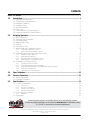
Each QB Series balance comes with the following components (see Figure 1-1 on page 2).
• AC adapter
• Weighing platform (round or rectangle, model dependent)
• Weighing platform support (size is model dependent)
Be sure all components have come with your QB Series balance.
NOTE: Store the packing material and box in a safe, easily accessible place. Should you ever need to transport the
balance across any substantial distance, using the original packing material is the first step to protecting your
investment.
Introduction
1
Weighing Platform
(both styles)
Platform Support
E
RIC
Adaptor
Connector
QB
T
ER
OV
PT
CE
AC
R
DE
UN
F
P
ON
F
OF
Level Indicator
E
LAK
Expansion Bay
Display
Leveling Leg (4)
AC Adaptor
Figure 1-1. Main Component Parts of the QB Series
1.2
General Care and Maintenance
To keep your QB Series balance operating properly, the device needs to be maintained and cared for. Keep the
housing and platform clean by wiping them off with a soft damp cloth daily. If necessary, use a slight solution of
water and dish soap to clean away stains and dirt. Check under the platform support area for any build up of dirt
and debris that could interfere with the mechanism. Keep your calibration masses in a safe, dry area. Unplug the
AC adapter when the device is not in use. For long term storage, remove the internal battery (if equipped).
1.3
Installation Guidelines
For optimum performance, we recommend that you use your QB Series device in a clean, stable environment.
Avoid the following:
• Excessive drafts
• Significant temperature and/or humidity changes
• Strong magnetic fields exist or equipment that may generate a magnetic field
• Excessive dust
• Unstable or vibrating work surface
• Corrosive gases or large amounts of dust
• Long-term exposure to direct sunlight
• Disassembling or modifying the unit in any way
• Moving the balance when an item is on the weighing platform
• Handling your balance with wet hands
• Shock loading or intentionally overloading the device
• Leaving the device exposed to direct sunlight
• Using any solvents on the device
2
QB Series Operation Manual
1.4
Installation Steps
Use the following steps to properly install the QB Series balance:
1. Inspect the leveling legs and ensure that they are all completely retracted.
2. Place the balance down on a firm, level mounting surface.
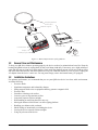
3. Using the bubble level to the upper left of the display panel as a guide, adjust the leveling legs as
necessary until the bubble is centered inside the bulls-eye of the bubble level (see Figure 1-2).
BALANCE IS LEVEL
BALANCE IS NOT LEVEL
Blue
circle
Bubble
Leveling leg
Figure 1-2. Level Adjustment
4. Plug the AC adapter into the back of the unit (see Figure 1-3).
Figure 1-3. AC Adapter Connection
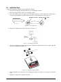
5. Secure the weighing pan support onto the device. Tighten the adjusting knob until it is finger tight. Do
not use a screwdriver (see Figure 1-4).
Adjusting
Knob
E
RIC
ER
OV
PT
CE
AC
R
DE
UN
E
LAK
QB
T
F
P
ON
F
OF
Figure 1-4. Attach Weighing Pan Support
6. Place the platform cover down over the weighing pan support (see Figure 1-1 on page 2 for exploded
view).
7. Plug the AC adapter into a suitable wall outlet.
Introduction
3
1.5
Special Information
The QB Series balance is a sensitive, precision weighing instrument and should always be treated with care.
While every attempt is made prior to shipping to ensure that your balance arrives ready-to-use, uncontrollable
events during the shipping process may make it necessary to calibrate the device before being used.
While not absolutely necessary, we recommend that you perform a span calibration prior to using the balance for
the first time. Even though your QB Series balance was carefully calibrated at the factory, shipping and the
effects of specific gravity can have a negative impact on accuracy. Review Section 3.0 on page 14 for instructions
on this feature.
In the event that the device fails to operate properly, contact your Rice Lake Weighing Systems dealer for
assistance.
1.6
Front Panel
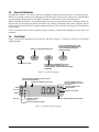
Figure 1-6 shows the QB Series keypad and key functions. Figure 1-7 on page 5 shows the LCD display
segments display.
Print key, or data transmission key.
ON
OFF
P
Tare key. In weighing mode, used
to tare weight. In calibration mode,
used to increment/decrement
parameter values.
F
Turns scale on or off.
T
Function key. In weighing mode, used
to select display unit of measure. In
calibration mode, used to select operational
parameters.
Figure 1-5. Front Panel Keypad
Memory function activated for values used in
limit or sampling functions.
Indicates weighing mode in
lb or oz (dependent on model)
See Table 2-1.
Indicates the battery charge is low.
OVER
M
LOW
lb
P
ACCEPT
Indicates supplemental
unit of measure.
Indicates count mode.
UNDER
Not used.
Indicates a negative
weighing value.
Indicates default weighing mode in grams.
Limit mode judgement results.
Figure 1-6. QB Series Display Segments
4
QB Series Operation Manual
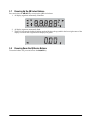
1.7
Powering Up the QB Series Balance
Press and release the ON/OFF key to turn on the QB Series balance.
1. All display segments momentarily illuminate.
M
lb
P
k
2. All display segments momentarily flash.
3. The device activates the default weighing mode and displays the g symbol in the lower right corner of the
display to indicate that weighments are displayed in grams.
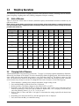
1.8
Powering Down the QB Series Balance
To turn the balance off, press and release the ON/OFF key.
Introduction
5
2.0
Weighing Operations
The following section describes weighing operations of the QB Series balance, including: units of measure,
general weighing, weighing with a tare, batching, comparator, and piece counting.
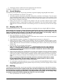
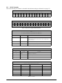
2.1
Units of Measure
Table 2-1 shows the various units of measure (maximum capacity and minimum increment) available on your
QB Series balance.
NOTE: There is no push-button conversion from one unit to another. The QB Series balance is capable of showing only
one unit of measure during a weighing operation. Switching to another unit of measure requires a change in the set up
procedure (see Section 2.2).
Unit of Measurement
(Display Symbol)
gram
(g)
kilogram
(kg)
carat
ounces
pound
(lb)
troy ounces
pennyweight
grain
HK tael
SIN tael
TW tael
momme
Conversion
Factor/g
QB-150E QB-300E QB-600E QB-620E QB-1500E QB-3000E QB-6000E QB-6200E QB-12KE
150 x
0.01
0.15 x
0.00001
750 x
0.05
5.2 x
0.0005
0.33 x
0.00002
4.8 x
0.0005
96 x
0.005
2300 x
0.2
4 x .0002
3.9 x
0.0002
4x
0.0002
40 x
0.002
300 x
0.01
0.3 x
0.00001
1500 x
0.05
10 x
0.0005
0.66 x
0.00002
9.6 x
0.0005
190 x
0.005
4600 x
0.2
8x
0.0002
7.9 x
0.0002
8x
0.0002
80 x
0.002
600 x
0.02
0.6 x
0.00002
3000 x
0.1
21 x
0.0005
1.3 x
0.00005
19 x
0.0005
380 x
0.01
9200 x
0.5
16 x
0.0005
15 x
0.0005
16 x
0.0005
160 x
0.005
620 x
0.01
0.62 x
0.00001
3100 x
0.05
21 x
0.0005
1.3 x
0.00002
19 x
0.0005
390 x
0.005
9500 x
0.2
16 x
0.0002
16 x
0.0002
16 x
0.0002
160 x
0.002
1500 x
0.1
1.5 x
0.0001
7500 x
0.5
52 x
0.005
3.3 x
0.0002
48 x
0.005
960 x
0.05
2300 x 2
40 x
0.002
39 x
0.002
40 x
0.002
400 x
0.02
3000 x
0.1
3x
0.0001
15000 x
0.5
100 x
0.005
6.6 x
0.0002
96 x
0.005
1900 x
0.05
46000 x
2
80 x
0.002
79 x
0.002
80 x
0.002
800 x
0.02
6000 x
0.2
6x
0.0002
3000 x 1
210 x
0.005
13 x
0.0005
190 x
0.005
3800 x
0.1
92000 x
5
160 x
0.005
150 x
0.005
160 x
0.005
1600 x
0.05
6200 x
0.1
6.2 x
0.0001
31000 x
0.5
210 x
0.005
13 x
0.0002
190 x
0.005
3900 x
0.05
95000 x
2
160 x
0.002
160 x
0.002
160 x
0.002
1600 x
0.02
12000 x
1
12 x
0.001
60000 x
5
420 x
0.05
26 x
0.002
380 x
0.05
7700 x
0.5
180000 x
20
320 x
0.02
310 x
0.02
320 x
0.02
3200 x
0.2
1
0.001
0.2
28.349527
453.5924
31.103481
1.5551740
0.0647989
37.428932
37.799466
37.5
3.75
Table 2-1. Unit Capacities
2.2
Changing Units of Measure
After the balance has been powered up (see Section 1.7 on page 5), all display segments momentarily illuminate,
followed by two flashes of all displays. The device then displays default weighing mode. If the balance does not
show a 0.00 value after the normal start sequence, press and release the T key. The balance returns to a 0.00
value. The default unit of measure from the factory is g (grams). If the balance has already been used, a different
unit of measure may already be activated. To change the active unit of measure, use the following steps:
1. Ensure that there is nothing on the platform and that the weight reading is 0.00.
2. Press and hold the F key until the word Func is displayed.
3. Release the F key. The display changes to show either 1.SET.1 or 1.SET.2.
4. Repeatedly press and release the F key to change the display, until it reads 7.un.1 (if the active unit of
measure is currently g). If the active unit of measure is another value, 7.un. is displayed, followed by any
one of the following values: 2, 3, 4, 5, 6, 7, 8, 9, A, b, or C.
5. Refer to Table 2-1 above and Table 4-1 on page 15 to determine the setting required for the desired unit
of measure.
6. Repeatedly press and release the T key until the appropriate value is displayed.
7. Press and release the P key to confirm the setting.
6
QB Series Operation Manual
8. The display returns to a 0.00 value for the appropriate unit of measure.
To change to a different unit of measure, repeat steps 1 – 9 above.
2.3
General Weighing
The following section provides a step-by-step procedure on general weighing using the QB Series balance.
1. Power up the balance (see Section 1.7 on page 5).
2. All display segments momentarily illuminate, followed by two flashes of all displays. The device then
displays default weighing mode. To change the default unit of measure, please refer to Section 2.2 on
page 6. If the balance does not show a 0.00 value after the normal start sequence, press and release the T
key. The device returns to a 0.00 value.
3. Gently place the item to be weighed on the platform. The unit of measure indicator begins to flash
indicating the balance is registering the weight of the commodity. The value display begins to update.
When the unit of measure indicator ceases flashing, the device is stable and you can read the weight
value.
2.4
Weighing with a Tare
The following section provides a step-by-step procedure on weighing with a tare using the QB Series balance.
NOTE: Whenever the tare function is activated, the effective weighing range of the device is reduced by the value of the
tare. For example, on a QB-600 with a total capacity of 600g, if a tare of 100g is entered into the balance, the total
effective NET weighing range of the device is only 500g (total rated capacity [600g] - tare value [100g] = 500g. Any
attempt to weigh over the effective weighing range results in a “o-Err” error message.
1. Power up the balance (see Section 1.7 on page 5).
2. The balance displays default weighing mode. If the balance does not show a 0.0 value after the normal
start sequence, press and release the T key.
3. The default unit of measure is displayed. To change the unit of measure, see Section 2.2.
4. Gently place the empty container on the platform. The unit of measure indicator begins to flash,
indicating that the balance is registering the weight of the commodity. The value display begins to
update. When the unit of measure indicator ceases flashing, the balance is stable and you can read the
weight value.
5. Press the T key. The zero display (0.00) appears.
NOTE: The value of the original tare must be ≥ +/- 4 displayed divisions from zero. If the original tare
value is ≤ +/- 3 divisions from zero, the device automatically re-establishes a new zero setting before the
T button can be activated. The tare function is not available. To disable this “auto-zero” feature, please
refer to Section 4.0 on page 15.
6. Gently place the product to be weighed in the previously tared container. The unit of measure indicator
begins to flash indicating that the balance is registering the weight of the commodity. The displayed
value begins to update. Continue adding commodity until the display indicates the desired weight value.
When the unit of measure indicator ceases flashing, the device is stable and you can read the weight
value.
NOTE: To view the gross weight of the commodity and the tare, remove the container with its contents
from the weighing platform. The total weight is displayed as a negative number. To return to normal
weighing, replace the container with its contents on the platform.
7. To weigh another commodity and tare or to re-use the current tare and weigh additional samples, remove
the commodity and container from the platform and press the T key to have the display return to a 0.00
reading, then repeat steps 1– 6.
2.5
Batching
The following section provides a step-by-step procedure on using the batching feature of the QB Series balance.
NOTE: Whenever the tare function is activated on a QB balance, the effective weighing range of the device is reduced by
the value of the tare. For example, on a QB-600 with a total capacity of 600g, if a tare of 100g is entered into the balance,
the total effective NET weighing range of the balance is only 500g (total rated capacity [600g] - tare value [100g] = 500g).
Any attempt to weigh over the effective weighing range results in a “o-Err” error message.
1. Power up the balance (see Section 1.7 on page 5).
Weighing Operations
7
2. The balance displays default weighing mode. If the balance does not show a 0.0 value after the normal
start sequence, press and release the T key.
3. The default unit of measure is displayed. To change the unit of measure, see Section 2.2.
4. Gently place the empty container on the platform. The unit of measure indicator begins to flash
indicating the device is registering the weight of the commodity. The value display begins to update.
When the unit of measure indicator ceases flashing, the balance is stable and you can read the weight
value.
5. Press the T key. The zero display (0.00) appears.
NOTE: The tare value must be ≥ ± 4 display divisions from zero. If the tare value is ≤ ± 3 divisions from
zero, the device automatically re-establishes a new zero setting before the T button can be activated.
The tare function is not available. To disable this auto-zero feature, please refer to Section 4.0 on
page 15.
6. Gently place the commodity to be weighed in the previously tared container.
7. The unit of measure indicator begins to flash indicating the device is registering the weight of the
commodity.
8. The value display begins to update.
9. Continue adding commodity until the display indicates the desired weight value.
10. When the unit of measure indicator ceases flashing, the device is stable and you can read the weight
value.
11. Without removing the product, press the T key.
12. Gently add the next product quantity. Only the net weight of the new commodity is displayed.
13. Repeat steps 11 and 12 as necessary.
NOTE: To view the gross weight of the commodity and the tare, remove the container with its contents
from the weighing platform. The total weight is displayed as a negative number. To return to normal
weighing, replace the container with its contents on the platform.
2.6
Removing the Tare
Use the following steps to remove a tare value from the QB balance:
1. Remove the container (empty or full) from the weighing platform.
2. The display shows the weight of the container and the commodity, if any, as a negative value.
3. Press and release the T key.
4. The display returns to a 0.0 value.
2.7
Weighing with the Comparator Function
The QB Series balance is equipped with an onboard comparator function that determines how the weight of a
commodity relates to a pre-determined over/under zone. This feature can help alleviate weighing errors and
speed up the judgement-making process. Rather than reading a weight value and making a mental calculation as
to whether or not the value is acceptable, the operator can simply concentrate on the OVER, UNDER and ACCEPT
indicators to determine whether a weight value is acceptable or not. The comparator function is not available in
the counting mode.
NOTE: When the counting mode is activated, the comparator function is automatically deactivated. Should you desire to
return to the comparator function, all of the most recently entered parameters are automatically recalled when the
counting function is deactivated (see Section 2.9 on page 12).
2.7.1
Comparator Function Activation
Prior to using the comparator function, the parameters for the operation must be programmed into the device.
Use the following steps to program the parameters for the comparator function.
1. Power up the balance (see Section 1.7 on page 5).
2. The balance displays default weighing mode. If the balance does not show a 0.0 value after the normal
start sequence, press and release the T key.
3. The default unit of measure is displayed. To change the unit of measure, see Section 2.2.
4. Press and hold the F key until the word Func is displayed.
8
QB Series Operation Manual
5. Release the F key. The display changes to show either 1.SET.1 or 1.SET.2. If the display shows 1.SET.1,
continue with step 6 below. If the display shows 1.SET.2, press and release the T key once to change the
value to 1.SET.1, then continue with step 6 below.
6. Press and release the F key once. The display changes to read 2.SEL.1. This indicates that the comparator
function is currently inactive.
7. Press and release the T key once. The display changes to read 2.SEL.2. This indicates that the comparator
function is active.
8. Press and release the F key once. The display changes to read 21.Co.X, where “X” is a value of either 1 or
2. Continue with Section 2.7.2 to establish the basic parameter configuration of the comparator function.
2.7.2
Basic Over/Under Parameter Selection
1. With the display reading 21.Co.X, where “X” is a value of either 1 or 2, (see step 8, Section 2.7.1 above),
determine if you wish to have the comparator function with only a stable weight reading (recommended)
or for all weight readings. If you wish to have a comparison done for only stable weight readings press
and release the T key until the display reads 21.Co.2. If you wish to have a comparison done for all
weight readings, press and release the T key until the display reads 21.Co.1.
2. Press and release the F key once. The display changes to read 22.Li.X where “X” is a value of either 0 or 1.
3. Determine if you wish to have a comparison performed for the entire weighing range of the balance, or if
you wish to exclude comparisons for values close to zero and for negative values (recommended). If you
wish to have comparisons performed for the entire weighing range of the balance, press and release the T
key until the display reads 22.Li.1. If you wish to have comparisons excluded for values close to zero and
for negative weight values (recommended), press and release the T key until the display reads 22.Li.0.
4. Press and release the F key once. The display changes to read 23.bu.X, where “X” is a value of either 0,
1, 2, 3, 4, 5, or 6.
5. Determine which of the following visual indications you would prefer for the various over/under/accept
conditions.
Parameter Value
Indication
23.bu.0
Solid arrow next to appropriate display legend
23.bu.1
Flashing arrow next to UNDER display legend. Solid arrow next to ACCEPT and OVER display legends
23.bu.2
Flashing arrow next to ACCEPT display legend. Solid arrow next to UNDER and OVER display legends
23.bu.3
Flashing arrow next to OVER display legend. Solid arrow next to UNDER and ACCEPT display legends
23.bu.4
Flashing arrow next to UNDER and ACCEPT display legends. Solid arrow next to OVER display legend
23.bu.5
Flashing arrow next to ACCEPT and OVER display legends. Solid arrow next to UNDER display legend
23.bu.6
Flashing arrow next to ACCEPT, UNDER, and OVER display legends
Table 2-2. Over/Under Parameter Values
6. Press and release the T key repeatedly until the appropriate parameter value from Table 2-2 is selected.
7. Press and release the P key once. The display returns to a 0.00 reading and the arrows next to the display
legends OVER, UNDER, and ACCEPT flash continuously indicating that upper and lower limits need to be
established. Continue with Section 2.8.3 on page 11.
NOTE: If the OVER, UNDER and ACCEPT arrows are not flashing, one of two conditions exist. Either the
comparator function has not been turned on correctly, or there are UPPER and LOWER comparison
limits already programmed into the unit. Verify that the comparator function is properly activated (see
Section 2.7.1 on page 8), then continue with Section 2.8 below.
2.8
Setting the Upper and Lower Comparison Limits
There are two methods for establishing the upper and lower comparison limits – the reference sample method
and the digital reference method. Section 2.8.2 on page 10 discusses the reference sample method where samples
of commodity that exactly represent the upper and lower limits are weighed and memorized by the balance.
Section 2.8.2 on page 10 discusses the digital reference method where the upper and lower limits are known
values and can therefore be digitally keyed into the balance.
Weighing Operations
9
2.8.1
Reference Sample Method
Use the following steps to establish upper and lower comparison limits in the QB Series balance using the
reference sample method.
1. Press and hold the P key until the display reads L Set, then release the P key.
2. The following indicators flash simultaneously – unit of measure, 0.00 weight value or the previously
entered lower limit value, under arrow, and M.
3. Place a commodity on the weighing platform that represents the minimum acceptable weight value.
4. Press and release the F key once.
5. The display continues to flash showing the unit of measure, minimum acceptable weight value, under
arrow, and M (see Figure 1-7 on page 5). Write down these values for future reference.
6. Press and release the P key once.
7. The display momentarily indicates H Set.
8. The following indicators then flash simultaneously: unit of measure, 0.00 weight value, over arrow (#)
and M (see Figure 1-7 on page 5).
9. Place a commodity on the weighing platform that represents the maximum acceptable weight value.
10. Press and release the F key once.
11. The display momentarily blanks, followed by a flashing display showing the unit of measure, maximum
acceptable weight value, over arrow and M (see Figure 1-7 on page 5). Write down this value for future
reference.
12. Press and release the P key once. The OVER indicator flashes and the weight display shows the value
used in step 9.
13. Remove the sample from the weighing platform. The display returns to a 0.00 value and the over arrow
(#) disappears.
2.8.2
Digital Reference Method
Use the following steps to establish upper and lower comparison limits in the QB Series balance using the digital
reference method.
1. Ensure that you have followed the instructions in Sections 2.7.1 and 2.7.2 on page 9, then continue
below.
2. Determine and write down the values you need to use as the lower limit and upper limit values.
3. The display shows a 0.00 reading and the arrows next to the display legends OVER, UNDER, and
ACCEPT flash continuously indicating that over and under limits need to be established. Continue with
Section 2.8.3 on page 11.
NOTE: If the OVER, UNDER, and ACCEPT arrows are not flashing one of two conditions exists. Either the
comparator function has not been turned on correctly (see Section 2.7.1 on page 8), or there are OVER
and UNDER comparison limits already programmed into the unit. Verify that the comparator function is
properly activated (see Section 2.7.1 on page 8). Continue with Section 2.8.4 on page 11.
4. Press and hold the P key until the display reads L Set, then release the P key.
5. The following indicators flash simultaneously: unit of measure, 0.00 weight value or the previously
entered lower limit value, under arrow, and M (see Figure 1-7 on page 5).
6. Press and release the T key once. With the exception of the least significant digit, the display stops
flashing, and indicates all zeros, or the last lower limit value entered.
7. Press and release the T key once. The flashing digit changes by a value of one.
8. Continue to press and release the T key until the flashing digit reads the value you desire.
9. Press and release the F key once. The value selected in step 8 above is set. The digit stops flashing and
the next most significant digit begins to flash.
10. Repeat steps 7 – 9 as necessary until the display reads the value you desire as the lower limit value.
11. If you need to change a digit once it has been set, repeatedly press and release the F key until the value
you want to change is flashing. Then return to steps 7 – 9.
12. Once the balance reads the correct lower limit value, press and release the P key once. The entire display
flashes showing the value you have selected as the lower limit value.
13. Press and release the P key again. The display momentarily reads H Set.
10
QB Series Operation Manual
14. The following indicators flash simultaneously: unit of measure, 0.00 weight value or the previously
entered upper limit value, over arrow (#), and M (see Figure 1-7 on page 5).
15. Press and release the T key once. With the exception of the least significant digit, the display stops
flashing, and indicates all zeros, or the last upper limit value entered.
16. Press and release the T key once. The flashing display changes by a value of one.
17. Continue to press and release the T key until the flashing display reads the value you desire.
18. Press and release the F key once. The value selected in step 17 above is set. The display stops flashing
and the next most significant digit begins to flash.
19. Repeat steps 17 and 18 as necessary until the display reads the value you desire as the upper limit value.
20. If you need to change a digit once it has been set, repeatedly press and release the F key until the value
you want to change is flashing. Then return to steps 17 and 18.
21. Once the balance reads the correct upper limit value, press and release the P key once. The entire display
flashes showing the value you have selected as the lower limit value.
22. Press and release the P key again. The display returns to the weighing mode showing a 0.00 value.
2.8.3
Weighing with the Comparator Function
Once the comparator function has been activated (see Section 2.7.1 on page 8) and upper and lower limit values
have been set (see Section 2.8 on page 9), use with the following steps to weigh with the comparator function:
1. Place a commodity on the weighing platform that is exactly equal to the lower limit value. The ACCEPT
indicator should illuminate confirming that any sample ≥ the lower limit value is acceptable. If not,
return to Section 2.8.1 or 2.8.2 on page 10 to re-enter the lower limit value.
2. Place a commodity on the weighing platform that is exactly equal to the upper limit value. The ACCEPT
indicator should illuminate confirming that any sample ≤ the upper limit value is acceptable. If not,
return to Section 2.8.1 or 2.8.2 on page 10 to re-enter the upper limit value.
3. Once the lower and upper limits are functioning correctly, any sample that is ≤ the upper limit value and
≥ the lower limit value is acceptable.
4. Remove the test sample from the platform.
5. If the balance does not show a 0.00 value, press and release the T key. The balance returns to a 0.00
value.
6. If applicable, place an empty container on the platform and press the T key. The balance returns to a 0.00
reading (see Section 2.4 on page 7)
7. Gently place the item to be weighed on the platform. The unit of measure indicator begins to flash
indicating the balance is registering the weight of the commodity. The displayed value begins to update.
When the unit of measure indicator ceases flashing, the balance is stable and displays the weight value
along with the appropriate OVER, UNDER or ACCEPT indicator illuminated.
2.8.4
Deactivating the Comparator Function
Use the following steps to deactivate the comparator function in the QB Series balance.
1. Press and hold the F key until the word Func is displayed.
2. Release the F key. The display changes to show 1.SET.1.
3. Press and release the F key once. The display changes to read 2.SEL.2. This indicates that the comparator
function is currently active.
4. Press and release the T key once. The display changes to read 2.SEL.1. This indicates that the comparator
function is inactive. Any existing over/under parameters remain in memory, but are inactive.
5. Press and hold the F key for approximately four seconds. The display returns the conventional weighing
mode and the comparator function is inoperative.
Weighing Operations
11
2.9
Operating the Counting Function
The QB Series balance is capable of functioning as a counting device, enabling it to determine quantity as
opposed to weight. In order to perform this function, the balance must be programmed with the average piece
weight of the sample being evaluated. Once programmed, the balance performs the following calculation to
determine the total number of pieces to display:
Weight on platform - tare weight (if applicable) / average piece weight = displayed piece count
NOTE: When the counting mode is activated, the comparator function is automatically deactivated. Should you desire to
return to the comparator function, all of the most recently entered parameters are automatically recalled when the
counting function is deactivated. If you need to return to the counting mode at a later time, the last average piece weight
utilized is still active.
2.9.1
Counting Function Activation
Prior to using the counting function, the parameters for the operation must be programmed into the balance.
1. Power up the balance (see Section 1.7 on page 5).
2. The balance displays the default weighing mode. If the balance does not show a 0.00 value after the
normal start sequence, press and release the T key.
3. Press and hold the F key until the word Func is displayed.
4. Release the F key. The display changes to show either 1.SET.1 or 1.SET.2. If the display shows 1.SET.2,
continue below with step 5. If the display shows 1.SET.1, press the T key once to change the value to
1.SET.2 and then continue with step 5 below.
5. Press and release the P key once. The display advances to the weighing mode with a 0 value and the P
(counting pieces) indicator illuminated.
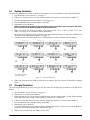
2.9.2
Programming the Average Piece Weight
To program the average piece weight, use the steps outlined below.
NOTE: The QB series balance can determine the average piece weight by evaluating initial samples of 10, 30, 50, or 100
pieces. We strongly recommend that you always use a sample of 100 pieces to ensure the most uniform sample piece
calculation resulting in the most accurate counting operation possible based on the samples provided. It is important to
remember that an accurate counting function relies on a uniformity of parts being counted. If there is a large variance
from piece to piece, that error is introduced into the counting function with a resultant error in the value displayed by the
balance.
1. Press and release the T key once to ensure that the value on the display is 0.
2. If you desire to use a container to hold the parts to be counted, place the empty container on the weighing
platform.
3. The display may change to indicate a counting value. Press and release the T key to return the display to
a 0 value.
NOTES:
•
•
The tare value must be ≥ +/- 4 display divisions from zero. If the tare value is ≤ +/- 3 divisions from
zero, the balance automatically re-establishes a new zero setting before the T button can be
activated. The tare function is not available. To disable this “auto-zero” feature, please refer to
Section 4.0 on page 15.
Whenever the tare function is activated on a QB balance, the effective weighing range of the device
is reduced by the value of the tare. For example, on a QB-600 with a total capacity of 600g, if a tare
of 100g is entered into the device, the total effective NET weighing range of the balance is only 500g
(total rated capacity [600g] - tare value [100g] = 500g. Any attempt to weigh over the effective
weighing range results in a “o-Err” error message.
4. Press and hold the F key until the display reads U Set. Then release the F key.
5. The display shows on xxx where “xxx” is either 10, 30, 50, or 100 depending on what value was last used
to determine an average piece weight.
6. Repeatedly press and release the T key until the display reads on 100 (recommended) or the quantity you
desire to use as a sample.
7. With the display flashing the number of pieces you have chosen to use as a sample, place those items on
the weighing platform or in the empty container.
8. Press and release the F key once. The display momentarily blanks, except for the flashing M indicator
which confirms that the balance is memorizing the average piece weight.
12
QB Series Operation Manual
NOTES:
•
•
It is possible to use a sample that is too light for the balance to accurately calculate an average
piece weight. If you notice that the display momentarily shows ADD followed by a display that
includes an illuminated UNDER annunciator, you have attempted to use a sample that is too light for
the device to accurately calculate an average piece weight. Continue adding additional samples and
pressing the F key until the UNDER annunciator goes out or simply return to step 4 and utilize a
larger sample.You can abort a sample evaluation at any time by pressing and releasing the P key
once. The display momentarily displays STOP followed by a counting value display.
The minimum average piece weight must be ≥ the minimum increment (readability) of the balance
being used. If you notice that the display momentarily shows L-Err, the commodity in question can
not be counted with this balance.
9. The display then resumes flashing. To begin counting based on the current average piece weight
calculation, press and release the P key once. The display stops flashing and the M indicator disappears.
The balance shows the current quantity of the commodity on the weighing platform. Proceed to
Section 2.9.4 on page 13.
10. To utilize the QB’s exclusive APWR (Automatic Piece Weight Refinement) program, continue with
Section 2.9.3 on page 13 (recommended).
2.9.3
Using the APWR (Automatic Piece Weight Refinement) Program
The APWR program is an exclusive feature of the QB Series. When utilized, its unique capabilities refine the
average piece weight as often as desired to take into consideration the largest sample possible. As the average
piece weight of a commodity is refined, the overall counting results are dramatically improved. Within the net
weighing range of the balance, there is no limit as to how many samples are used.
1. Complete steps 1 – 8 in Section 2.9.2 on page 12.
2. With the display flashing the sample count, M indicator and P indicator, add any number of additional
samples to those already being weighed.
3. Press and release the F key once. The display momentarily blanks, except for the flashing M indicator
which confirms that the balance is calculating and updating the previously memorized average piece
weight. Repeat steps 2 and 3 as many times as desired.
4. When you are ready to exit the APWR, press and release the P key once. The display stops flashing the
the M indicator disappears.
2.9.4
Using the Counting Mode
Use the following steps to perform piece count operations on the QB Series balance.
1. Complete the steps in Section 2.9.1 – 2.9.3 as appropriate.
2. Remove the test sample from the platform.
3. If the balance does not show a 0 value, press and release the T key. The balance returns to a 0 value.
4. If applicable, place an empty container on the platform and press the T key. The balance returns to a 0
reading (see Section 2.4 on page 7).
5. Gently place the items to be counted on the weighing platform or in the empty container as appropriate.
6. The P annunciator begins to flash as the display updates. When the P annunciator stops flashing, you can
read the quantity of commodity being evaluated.
2.9.5
Deactivating the Counting Mode
Use the following steps to deactivate the count mode of the QB Series balance.
1. Press and hold the F key until the word Func is displayed (U SET appears first, followed by Func).
2. Release the F key. The display changes to show 1.SET.2.
3. Press and release the T key once to change the value to 1.SET.1. This deactivates the counting mode.
4. Press and release the P key once. The display advances to the weighing mode with a 0.00 value.
5. Even though the counting mode has been deactivated, the most recently used average piece weight
remains in memory and is recalled when the counting mode is reactivated.
Weighing Operations
13
3.0
Span Calibration
To achieve optimum accuracy from your QB Series balance, it should be calibrated on a regular basis in the
environment in which it is normally used. If the device is moved to another physical environment, recalibrate the
device before using it. A few extra moments invested with this section will ensure virtually error-free
performance of the device.
After properly performing the installation guidelines (see Section 1.3 on page 2 and Section 1.4 on page 3),
follow these calibration steps.
1. Power up the balance (Section 1.7 on page 5).
2. Have ASTM Class 4 test weights available equal to 100% of the nominal capacity (in grams) of the
device. (Weights and weight sets are available from Rice Lake Weighing Systems.)
3. Ensure that there is no load on the platform.
4. Ensure that the device is level and on a stable surface, free from environmental changes. Pay special
attention to possible and sudden changes in humidity, temperature and moving air.
5. Ensure that the balance displays a 0 or 0.00 value. If not, press and release the T key once.
6. If the device is currently using any unit of measure other than grams, activate the grams unit of measure
(Section 2.2 on page 6).
7. If the device is currently in the counting mode, reactivate the conventional weighing mode (see
Section 2.9.5 on page 13).
8. Press and hold the F key until the word CAL appears. As you press and hold the F key for approximately
two seconds, the word FUNC appears. The word CAL appears after two additional seconds.
9. When the word CAL appears, release the F key. If you hold the F key down too long, the unit returns to
the default weighing mode. If this occurs, start over at step 8.
10. While pressing and holding the T key, press and hold the F key. Release both keys at the same time. The
display shows unit 1 where 1 represents the function code for the grams unit of measure as active.
11. Press and release the F key.
12. The device momentarily displays a flashing on 0, indicating an automatic calibration of true mechanical
zero.
13. After zero calibration, the device automatically advances to read on F.S.
14. Place a load equal to the nominal capacity of the device on the center of the platform.
15. The on FS display flashes, indicating that the device is electronically calibrating a full scale load
equivalent to the nominal capacity of the device.
16. When calibration is complete, the device automatically displays the calibrated nominal capacity of the
balance.
17. Remove the test load from the balance.
18. The device automatically returns to a 0.0 value and the default weighing mode.
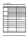
In some rare cases, automatic calibration may not be possible. In the event of an error message during
calibration, please refer to the table below for the appropriate corrective action.
Error Message
O-ERR
Problem
• Calibration load is in excess of the nominal capacity of the
device. The device is out of calibration and is sensing a
100% load being greater than the nominal capacity of the
device.
• The calibration test load is > 100% of the nominal
capacity.
Solution
• Change the test load so that it is
equal to 1/2 or 3/4 the nominal
capacity of the device. Then run a
second calibration at 100% nominal
capacity.
• Reduce the test load so that it is
equal to 100% of the nominal
capacity of the device.
1-ERR
Calibration load is less than 1/2 of the nominal capacity of the
device.
Increase the test load so that it is equal to
the nominal capacity of the device.
2-ERR
Data error is in excess of 1% of the rated capacity.
Contact your RLWS dealer.
Table 3-1. Possible Calibration Process Error Messages
14
QB Series Operation Manual
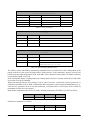
4.0
Function Parameters
The parameter menu allows you to activate or deactivate certain features and functions of the QB Series balance.
The following section provides information on the functions of the QB and how to view and change those
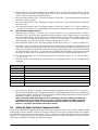
functions. Table 4-1 below describes the various functions of the QB.
NOTE: Bold type indicates factory setting.
Display
1.SET
Setting
1
Function
Mode Selection
2
2.SEL
1
2
21.CO
1
2
22.LI
0
1
23BU
0
1
2
3.AO
Comparator
Function
Comparator OFF
Conditional
Response
Parameter
(available only when
comparator is set
to ON)
Active when balance is stable and in motion
Range Response
Parameter
(available only when
comparator is set
to ON)
Inactive for data near zero and for negative data (recommended)
Response
Condition (available
only when the
comparator is set
to ON)
6.IF
Comparator ON
Active when balance is stable ONLY (recommended)
Active for the entire weighing range (all data)
Solid arrow next to appropriate display legend
Flashing arrow next to UNDER display legend.
Solid arrow next to ACCEPT and OVER display legends.
Flashing arrow next to ACCEPT display legend.
Solid arrow next to UNDER and OVER display legends.
3
Flashing arrow next to OVER display legend.
Solid arrow next to UNDER and ACCEPT display legends
4
Flashing arrow next to UNDER and ACCEPT display legends.
Solid arrow next to OVER display legend.
5
Flashing arrow next to ACCEPT and OVER display legends.
Solid arrow next to UNDER display legend.
6
Flashing arrow next to ACCEPT, UNDER, and OVER display legends.
0
Auto Zero
0
1
Auto zero function off
Auto zero function on (± 3d)
Sleep Mode
1
5.rE
Weighing mode only
Counting mode only
1
4.AP
Description
Sleep mode ON (available only when internal rechargeable battery installed).
Turns device off after three minutes of inactivity when running off of battery power.
Sleep mode OFF
Response Speed
Very fast (extremely stable environment)
2
Fast (stable environment)
3
Average (typical environment)
4
Slow (difficult environment)
5
Very slow (unstable working environment)
0
1
2
Baud rate (available
only when optional
RS-232 is installed).
Interface off or not installed
Continuous serial output (6-digit)
Continuous serial output (7-digit)
Table 4-1. Function List
Function Parameters
15
Display
61.0.C
Setting
Function
0
Output control
(available only when
interface option is
set to ON)
1
2
Description
Output prohibited (stop)
Continuous output
NOTE: When the RS-232C interface is installed, output interval of data in
constant transmission is 0.1 – 1 second, depending on the weighing condition
and response parameters of 5.rE.X above.
Continuous output when data is stable. No output when data is unstable.
NOTE: When RS-232C interface installed, output interval of data in constant
transmission is 0.1 – 1 second, depending on the weighing condition and
response parameters of 5.rE.X above.
3
Data output x 1 each time P key is pressed and released in weighing mode
4
Automatic output x 1 after data stablized
NOTE: Only one transmission is sent after a stabilization from an increasing load.
No additional output will be generated until the device returns to a 0.00 value and
resets for the next load.
62.6L
5
Automatic output x 1 of stable data; output prohibited if data unstable
6
Automatic output x 1 of stable data; continuous output of unstable data
7
Data output x 1 each time P key is pressed and released with data stablized
1
Baud rate (available
only when interface
option is set to ON)
1200 bps
None
2
Parity bit selection
(avalable only when
interface option is
set to ON)
1
Unit of measure
gram
2
3
63.PA
0
1
7.UN
2400 bps
4800 bps
Odd
Available only when option 6.IF.2 is selected
(parity bit available only in 7-digit format)
Even
2
kilogram
3
carat
4
decimal ounce
5
pound
6
troy ounce
7
pennyweight
8
grain
9
Hong Kong tael
A
Singapore tael
b
Taiwanese tael
C
momme
Table 4-1. Function List (Continued)
16
QB Series Operation Manual
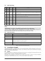
4.1
Viewing Parameters
The following information provides a step-by-step procedure to view the parameters of the QB Series balance.
1. Turn the balance on (see Section 1.7 on page 5).
2. If the device does not show a 0.0 value after the normal start sequence, press and release the P key.
3. Turn the counting function off (see Section 2.9.5 on page 13).
4. Press and hold the F key until the display reads FUNC.
5. Immediately release the F key.
NOTE: If you hold the F key down too long, the display changes from FUNC to CAL. Simply press and release
the P key to return to the default weighing mode and return to step 4.
6. When you release the F key, the display reads 1.SEt.X where “X” is a value of either 1 or 2. (see
Table 4-1 on page 15 for a definition of these parameters).
7. Press and release the F key again to advance to the next parameter display. Compare the information in
the display to the information in Table 4-1 on page 15.
8. Continue to press and release the F key to scroll through each of the parameter function displays.
Weight Unit
P
F
ON
OFF
T
P
F
Response Speed
Auto-power Off
➩
➩ 1.SEL . 2
1.S ET. 1
ON
OFF
Zero Tracking
➩ 22.L . 1
21.C . 2
ON
OFF
T
F
P
ON
OFF
T
P
F
T
➩
➩
ON
OFF
P
F
➩
5 . E. 3
Response Speed
Auto-power Off
4. AP. 1
ON
OFF
T
P
F
T
3. A . O 1
ON
OFF
F
P
Response Speed
➩
Response Speed
2 3.
T
ON
OFF
.2
P
F
T
➩
Weight Unit
➩ 6 1. . . 0
6 . IF. 1
ON
OFF
P
F
Output Control*
T
ON
OFF
P
F
Weight Unit
Weight Unit
➩ 62. .L. 1 ➩ 7.
T
ON
OFF
P
F
T
ON
OFF
. 1
P
F
T
*Only applies when device
is RS-232 equipped.
Figure 4-1. Function Parameters
9. When you press and release the F key after the last parameter, the device returns to the default weighing
mode.
4.2
Changing Parameters
The following information provides a step-by-step procedure for changing the parameters of the QB Series
balance.
1. Turn the balance on (see Section 1.7 on page 5).
2. Ensure there is no load on the platform.
3. Ensure that the device is in the normal weighing mode, not the counting mode. To turn off the counting
mode and return to the normal weighing mode, see Section 2.9.5 on page 13.
4. If the device does not show a 0.0 value after the normal start sequence, press and release the T key.
5. Press and hold the F key until the display reads FUNC.
6. Immediately release the F key.
7. If you hold the F key down too long, the display changes from FUNC to CAL. Press and release the P key
to return to the default weighing mode and return to step 4.
8. When you release the F key, the display reads 1.SEt. 1.
Function Parameters
17
9. Using Table 4-1 on page 15 as a guide, scroll to the function you wish to change by repeatedly pressing
the F key. If you scroll through all of the functions, the device automatically returns to the conventional
weighing mode. To return to the function mode, return to step 5.
10. Once the function you wish to change is displayed, repeatedly press the T key until the parameter you
want to use is displayed.
11. To continue on to another function, return to step 9.
12. If you do not need to change another function, press the P key to confirm your settings and return to the
conventional weighing mode.
18
QB Series Operation Manual
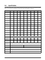
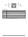
5.0
Specifications
This section contains tables listing common specifications and model specific data for the QB Series balance.
Table 5-1 below provides specifications of each of the models in the QB Series of balances.
Unit of Measure
(Display Symbol)
QB-150E
QB-300E
QB-600E
QB-620E
QB-1500E
QB-3000E
QB-6000E
QB-6200E
gram
(g)
150 x
0.01
300 x
0.01
600 x
0.02
620 x
0.01
1500 x
0.1
3000 x
0.1
6000 x
0.2
6200 x
0.1
12000 x 1
kilogram (kg)
0.15 x
0.00001
0.3 x
0.00001
0.6 x
0.00002
0.62 x
0.0001
1.500 x
0.0001
3x
0.0001
6x
0.0002
6.2 x
0.0001
12 x 0.001
carat
(")
750 x
0.05
1500 x
0.05
3000 x
0.1
3100 x
0.05
7500 x
0.5
15000 x
0.5
30000 x 1
31000 x
0.5
60000 x 5
ounce
(")
5.2 x
0.0005
10 x
0.0005
21 x
0.0005
21 x
0.0005
52 x
0.005
100 x
0.005
210 x
0.005
210 x
0.005
420 x 0.05
pound
(")
0.33 x
0.00002
0.66 x
0.00002
1.3 x
0.00005
1.3 x
0.00002
3.3 x
0.0002
6.6 x
0.0002
13 x
0.0005
13 x
0.0002
26 x 0.002
troy ounce
(")
4.8 x
0.0005
9.6 x
0.0005
19 x
0.0005
19 x
0.0005
48 x
0.005
96 x
0.005
190 x
0.005
190 x
0.005
380 x 0.05
pennyweight
(")
96 x
0.005
190 x
0.005
380 x
0.01
390 x
0.005
960 x
0.05
1900 x
0.05
3800 x
0.1
3900 x
0.05
7700 x 0.5
grain
(")
2300 x
0.2
4600 x
0.2
9200 x
0.5
9500 x
0.2
2300 x 2
46000 x 2
92000 x 5
95000 x 2
18000 x
20
HK tael
(")
4 x 0.002
8x
0.0002
16 x
0.0005
16 x
0.0002
40 x
0.002
80 x
0.002
160 x
0.005
160 x
0.002
320 x 0.02
Sing tael
(")
3.9 x
0.0002
7.9 x
0.0002
15 x
0.0005
16 x
0.0002
39 x
0.002
79 x
0.002
150 x
0.005
160 x
0.002
310 x 0.02
Taiwanese tael
(")
4x
0.0002
8x
0.0002
16 x
0.0005
16 x
0.0002
40 x
0.002
80 x
0.002
160 x
0.005
160 x
0.002
320 x 0.02
momme
(")
40 x
0.002
80 x
0.002
160 x
0.005
160 x
0.002
400 x
0.02
800 x
0.02
1600 x
0.05
1600 x
0.02
3200 x 0.2
Tare range
QB-12KE
100%, push-button
Percentage of
minimum division
0.025
0.05
0.05
0.1
0.025
0.05
0.25
0.1
0.1
Linearity (g)
±0.01
±0.01
±0.02
±0.01
±0.1
±0.1
±0.2
±0.1
±1
Repeatibility/
Standard Dev. (g)
±0.01
±0.01
±0.02
±0.01
±0.1
±0.1
±0.2
±0.1
±1
Sensitivity drift
(ppm/degree C/
span)
Pan size (mm)
Pan size (in)
±10
140∅
190 x 190
5.512∅
7.48 x 7.48
Physical
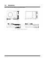
dimensions (mm)
See Figure 7-1 on page 27
Physical
dimensions (in)
See Figure 7-1 on page 27
Display
0.4724“ (12mm) 6-digit LCD
Table 5-1. Model Specific Data
Specifications
19
Unit of Measure
(Display Symbol)
QB-150E
QB-300E
Shipping weight
(lb)
QB-600E
QB-620E
QB-3000E
QB-6000E
1.27
QB-6200E
QB-12KE
1.59
Admissable RH%
80% RH (Non-condensing; max)
Admissable
ambient temp
0° - 40° C
32° - 104° F
Calibration
method
Calibration mass
(g)*
QB-1500E
Semi-automatic, external calibration with reference weight
150
300
600
620
Power
1500
3000
6000
6200
12000
115/230 VAC (via AC adapter) 50/60 Hz
Accessories
included
115 VAC adapter, operating instructions, in-use cover
Table 5-1. Model Specific Data (Continued)
* Recommended ASTM Class 4.
5.1
RS-232C Specifications
The QB Series may be equipped with an optional RS-232C feature (PN 42174), which is compatible for
communication with printers and computers. When the balance is connected directly to a printer, displayed data
can be output either via the P key on the balance, or automatically when certain conditions have been met. Refer
to Table 4-1 on page 15 for a list of parameters available.
NOTE: The optional battery pack (PN 42169) cannot be used simultaneously with the RS-232C option.
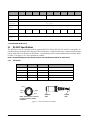
5.1.1
Pin Function
Pin Number
Signal
Output/Input
Function
1
Tare
Input
External tare input (1)
2
DTR
Output
High level with scale power ON
3
RXD
Input
Receiving data
4
TXD
Output
Transmission data
5
GND
N/A
Signal ground
Table 5-2. RS-232C Pin Function
Pin 2
Pin 4
Pin 5
Pin 1
Pin 3
NOTE: Printer side of connector
to show correct pin number
orientation.
Balance
side
Figure 5-1. RS-232 Connector Schematic
20
QB Series Operation Manual
Printer
side
5.1.2
RS-232C Commands
One of the following two formats is selectable in the function setting (see Section 4.0 on page 15).
6-digit data format
(Content: 14 words, including terminators; CR = 0DH, LF = 0AH)
1
2
3
4
5
6
7
8
9
10
11
12
13
14
P1
D1
D2
D3
D4
D5
D6
D7
U1
U2
S1
S2
CR
LF
Table 5-3. RS-232C 6-digit Command Format
7-digit data format*
1
2
3
4
5
6
P1
D1
D2
D3
D4
D5
7
8
9
10
11
12
13
14
15
D6
D7
D8
U1
U2
S1
S2
CR
LF
*Note inclusion of D8.
Table 5-4. RS-232C 7-digit Command Format
Data
D1 ~ D7, 7 words with 6-digit format (see Table 5-3)
D1 ~ D8, 8 words with 7-digit format (see Table 5-4)
D
Code
0~9
Contents
30H ~ 39H
Data 0 ~ 9
(Max 6 digits with 6-digit format or max 7 digits with
7-digit format)
.
2EH
Decimal point (floating)
sp
20H
Space; leading zero suppression
Table 5-5. Data
Polarity: P1 = 1 word
P1
Code
Contents
+
2BH
Data is 0 or positive
–
2DH
Data is negative
sp
20H
Data is 0 or positive
Table 5-6. Polarity
Units
(U1, U2 = 2 words, based on ASCII codes)
U1
U2
Contents
Symbol
k
g
kilogram
kg
p
c
quantity
(pcs)
m
o
momme
mom
l
b
pound
lb
d
w
pennyweight
dwt
t
l
tael
tl
Table 5-7. Units
Specifications
21
Units
(U1, U2 = 2 words, based on ASCII codes)
sp
g
gram
g
c
t
carat
ct
o
z
ounce
oz
o
t
troy ounce
ozt
g
g
grain
gr
Table 5-7. Units (Continued)
Conditional Response Parameter For Comparator Function
(S1 = 1 word)
S1
Code
Contents
l
4CH
Low (under)
g
47H
Good (accept)
h
48H
High (over)
Table 5-8. Conditional Response Parameter for Comparator Function
Status of Data
(S2 = 1 word)
S2
Code
Contents
s
53H
Data stabilized
u
55H
Data unstabilized
e
45H
Erroneous data; all data unreliable except S2 (device
display reads either “o-Err” or “u-Err”)
Table 5-9. Input Command, Data Reception
The balance can be controlled by transmitting commands from an external device and is independent of the
timing on the device due to the full duplex nature of the interface. If the command is properly received, the
balance transmits acknowledgement (ACK, code 06H). If the command is unacceptable, the balance transmits
non-acceptance (NAK, code 15H).
In the conventional display weighing mode (non-counting mode), the device responds with ACK or NAK within
one second of receipt of command.
When transmitting function code changes, such as unit of measure, conditional response parameter, or
calibration commands, ACK or NAK are transmitted after completion of the requested command process (e.g.,
when the new parameter has been set and confirmed). Commands that are sent before ACK or NAK are
transmitted from the device are ignored.
Input format command consists of four (4) words, including terminators (CR=0DH or LF=0AH) as follows:
1
2
3
4
C1
C2
CR
LF
C1
C2
CODE
Contents
T
sp
54h 20H
Tare Command
External tare command is as follows:
22
QB Series Operation Manual
5.1.3
Output Control Settings
C1
C2
Code 1
Code 2
Contents
0
0
4FH
30H
Interface off, no printing available
0
1
4FH
31H
Automatic continuous printing of zero display, unstable and stable weighing values
0
2
4FH
32H
Automatic continuous printing of stabilized data only (for example, stable 0 value and
stable weight value)
0
3
4FH
33H
Pushbutton printing from balance P key of stable 0 value and stable weight value
0
4
4FH
34H
Auto-printing of stabilized weight value only
0
5
4FH
35H
Auto-printing x 1 of stabilized zero value and stabilized weight value
0
6
4FH
36H
Auto-printing x 1 of any weight stable display value
0
7
4FH
37H
Pushbutton printing from balance P key of stable 0 value and stable weight value
0
8
4FH
38H
Automatic output x 1 of stable data; continuous output of unstable data
0
9
4FH
39H
Data output x 1 each time P key is pressed and released with data stabilized
Table 5-10. Output Control Settings
NOTES:
• The performance of the device can be controlled by output controls with commands 00-07 and by the parameter
settings (see Table 4-1 on page 15). Commands 08 and 09 are limited to an input command string.
• Once any command is initiated, that status is maintained until a new command is initiated. However, once the power is
turned off, the output control status returns to the setting previous to the last input command.
5.1.4
Interface Specifications
Item
Transmission method
Specification
RS-232C serial data, random access
Transmission speed
1200/2400/4800 bps; user selectable; (see Table 4-1 on page 15)
Transmission code
ASCII; 8-bit
Signal level
Contents of word
Parity bit
EIA RS-232C;
High Level - Data logic “0” + 5 VDC to +15 VDC
Low Level - Data logic “1” -5 VDC to -15 VDC
8-bit word based on ASCII standard character codes; 1 start bit; 2 stop bits; 0/1 parity bit
Null, even or odd parity
Table 5-11. RS-232C Interface Specifications
5.2
Connecting to a Computer
Connecting the balance to a computer enables you to operate the balance from the computer as well as receive
data such as displayed weight and unit of measure. The following sections describe the hardware and output
signal formats provided with the balance.
5.2.1
Hardware
A 5-pin DIN connector for interfacing to other devices (see Figure 5-2 on page 24) is located on the rear of the
QB Series balances equipped with the optional RS-232C interface.
The balance does not output any data unless pin 2 is held in an ON state (+5 VDC to +15 VDC). Interfaces
requiring the CTS handshake may tie pins 5, 4, and 8 on the computer side to defeat it.
Specifications
23
DB-25
Connection
TXD
RXD
GND
DCD
RTS
CTS
DSR
DTR
2
3
7
8
4
5
6
20
Jump pins
8, 4, and 5
3
4
5
1
RXD
TXD
GND
2
DTR
DIN-5
Balance
Connections
Jump pins
6 and 20
Figure 5-2. Connection to a Computer
5.3
Accessories
RLWS Part Number
Description
42566
115 VAC adapter for QB/MB Series balances
42168
230 VAC adapter for MB/QB/IB Series balances
42171
Internal rechargeable battery for QB Series (incompatible with PN 42174 below)
42174
RS-232C interface for QB Series (incompatible with PN 42171 above) includes DIN-5 pin connector
(cable not included)
42177
Glass breeze break for QB Series (scales with round weighing pans only)
42181
In-use cover
41555
Limit output pack
42194
Additional operating manual
Table 5-12. MB Series Balance Accessories
24
QB Series Operation Manual
6.0
Troubleshooting
The following section contains a troubleshooting chart for the QB Series scale. Refer to this chart to locate
causes and corrective actions to various conditions.
Condition
Display does not
stabilize
Cause
Corrective Action
• Wind or vibration is affecting scale
• Set up balance elsewhere or under a
protective hood
• Scale is set on unstable surface
• Set the scale on a firm surface that is free
from vibrations
• Span is out of calibration
• Level the scale
• Perform span and zero adjustment
• Tare value entered incorrectly
• Clear and re-enter tare value
• Balance is not set level
• Set balance level
• Span is out of calibration
• Perform span adjustment
• Interference with weigh pan or pan
support
• Check for foreign material under weigh pan
or weigh pan support
Linearity error
• Mechanical adjustment has changed
• Consult your local Rice Lake Weighing
Systems Service distributor
Display is blank
• Adapter is not connected
• Connect AC adapter to the scale and 120
VAC outlet
• Recharge battery
• Press the ON/OFF key
Displayed value is in
error
Weight value is drifting
• Battery needs recharging
• Auto Power OFF is activated.
• Device is not set to comparator mode
• Reference value is greater than the
nominal capacity of the device
• Lower limit value is ≥ upper limit value
• Turn on comparator mode
• Change reference value
Balance does not weigh
to nominal capacity
• Tare + sample weight exceeds capacity
• (Weight range = maximum capacity –
tare weight)
• Add the individual weights of the tare and
the commodity to determine if together they
are more than the nominal capacity of the
device
b-ERR
• Electronic
malfunction
due
to
e l e c t ro - s t a t i c d i s c h a r g e ( E S D ) o r
electro-magnetic interference (EMI)
• Consult your local Rice Lake Weighing
Systems distributor
L-ERR
• In counting mode, the unit weight of the
samples is less than the minimum
division of the device
• This commodity can not be counted with
this device
O-ERR
• Capacity is exceeded
• Use a test mass to ensure the balance can
weigh to its rated capacity
• Ensure that the commodity being weighed
is not in excess to the nominal capacity of
the balance
• Consult your local Rice Lake Weighing
Systems distributor
U-ERR
• Interference with the weighing pan or
weighing pan support
• Remove interference
Comparator limits can
not be established
• Change lower limit value
Table 6-1. Troubleshooting Chart
Troubleshooting
25
Condition
Cause
Corrective Action
1 - ERR
• The calibration weight is less than 1/2
full capacity
• Reinitiate calibration with a test mass equal
to the nominal capacity of the balance
• Consult your local Rice Lake Weighing
Systems distributor
2-ERR
• The data error exceeds 1%
• Defective weighing mechanism
• Consult your local Rice Lake Weighing
Systems distributor
3-ERR
4-ERR
• Calibration has started with a load on
the platter
• Remove load and reinitiate calibration
process
• Consult your local Rice Lake Weighing
Systems distributor
U - ERR
• Material wedged underneath
platform support plate
• Remove platform and platform support
plate, then clean and reassemble
the
Table 6-1. Troubleshooting Chart (Continued)
26
QB Series Operation Manual
7.0
Dimensions
208
208
Figure 7-1 below shows the dimensions of the QB Series balance.
310
310
Ø140
71
(87)
71
(86)
190
Figure 7-1. QB Series Dimensions
Dimensions
27
QB Series Limited Warranty
Rice Lake Weighing Systems (RLWS) warrants that all RLWS equipment and systems manufactured and sold by
RLWS and properly installed by an authorized RLWS Distributor or Original Equipment Manufacturer (OEM)
will operate per written specifications as confirmed by the Distributor/OEM and accepted by RLWS. All systems
and components are warranted against defects in materials and workmanship for five years.
RLWS warrants that the equipment sold hereunder will conform to the current written specifications authorized
by RLWS. RLWS warrants the equipment against faulty workmanship and defective materials. If any equipment
fails to conform to these warranties, RLWS will, at its option, repair or replace such goods returned within the
warranty period subject to the following conditions:
• Upon discovery by Buyer of such nonconformity, RLWS will be given prompt written notice with a
detailed explanation of the alleged deficiencies.
• Individual electronic components returned to RLWS for warranty purposes must be packaged to
prevent electrostatic discharge (ESD) damage in shipment. Packaging requirements are listed in a
publication, Protecting Your Components From Static Damage in Shipment, available from RLWS
Equipment Return Department.
• Examination of such equipment by RLWS confirms that the nonconformity actually exists, and was
not caused by accident, misuse, neglect, alteration, improper installation, improper repair or
improper testing; RLWS shall be the sole judge of all alleged non-conformities.
• Such equipment has not been modified, altered, or changed by any person other than RLWS or its
duly authorized repair agents.
• RLWS will have a reasonable time to repair or replace the defective equipment. Buyer is responsible
for shipping charges both ways.
• In no event will RLWS be responsible for travel time or on-location repairs, including assembly or
disassembly of equipment, nor will RLWS be liable for the cost of any repairs made by others.
THESE WARRANTIES EXCLUDE ALL OTHER WARRANTIES, EXPRESSED OR IMPLIED,
INCLUDING WITHOUT LIMITATION WARRANTIES OF MERCHANTABILITY OR FITNESS FOR
A PARTICULAR PURPOSE. NEITHER RLWS NOR DISTRIBUTOR WILL, IN ANY EVENT, BE
LIABLE FOR INCIDENTAL OR CONSEQUENTIAL DAMAGES.
RLWS AND BUYER AGREE THAT RLWS’ SOLE AND EXCLUSIVE LIABILITY HEREUNDER IS
LIMITED TO REPAIR OR REPLACEMENT OF SUCH GOODS. IN ACCEPTING THIS WARRANTY,
THE BUYER WAIVES ANY AND ALL OTHER CLAIMS TO WARRANTY.
SHOULD THE SELLER BE OTHER THAN RLWS, THE BUYER AGREES TO LOOK ONLY TO THE
SELLER FOR WARRANTY CLAIMS.
NO TERMS, CONDITIONS, UNDERSTANDING, OR AGREEMENTS PURPORTING TO MODIFY
THE TERMS OF THIS WARRANTY SHALL HAVE ANY LEGAL EFFECT UNLESS MADE IN
WRITING AND SIGNED BY A CORPORATE OFFICER OF RLWS AND THE BUYER.
© 2003 Rice Lake Weighing Systems, Inc. Rice Lake, WI USA. All Rights Reserved.
RICE LAKE WEIGHING SYSTEMS • 230 WEST COLEMAN STREET • RICE LAKE, WISCONSIN 54868 • USA