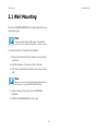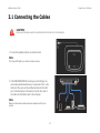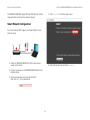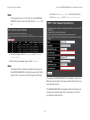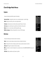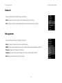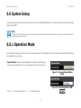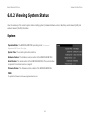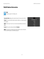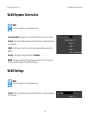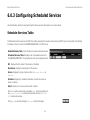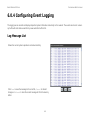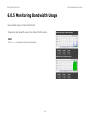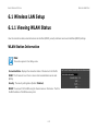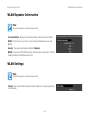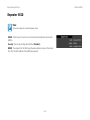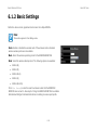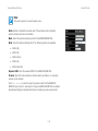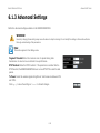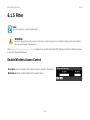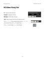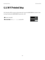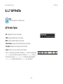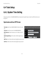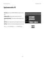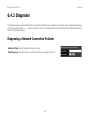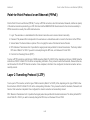
1
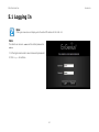
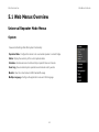
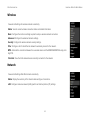
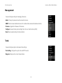
EnGenius® X-TRA RANGE® ERB300H/ERB150H Wireless-N HD Media Bridge & Range Extender User Guide V1.0 TABLE OF CONTENTS TABLE OF CONTENTS Product Overview Product Overview 1-1 Hardware Features . . . . . . . . . . . . . . . . . . . . . . . . . . . . . . . . . . . . . . . . . . . . . . . . . . .1-1 Software Features . . . . . . . . . . . . . . . . . . . . . . . . . . . . . . . . . . . . . . . . . . . . . . . . . . . .1-2 Technical Specification . . . . . . . . . . . . . . . . . . . . . . . . . . . . . . . . . . . . . . . . . . . . . . . . .1-2 Physical Interface . . . . . . . . . . . . . . . . . . . . . . . . . . . . . . . . . . . . . . . . . . . . . . . . . . .1-2 Wireless Specification . . . . . . . . . . . . . . . . . . . . . . . . . . . . . . . . . . . . . . . . . . . . . . . .1-2 Hardware Specification . . . . . . . . . . . . . . . . . . . . . . . . . . . . . . . . . . . . . . . . . . . . . . .1-2 Package Contents 1-4 Product Layout 1-5 Installation System Requirements 2-1 Wall Mounting 2-2 I TABLE OF CONTENTS EnGenius Quick Start Installing the Software 3-1 Setup Notes . . . . . . . . . . . . . . . . . . . . . . . . . . . . . . . . . . . . . . . . . . . . . . . . . . . . . . . .3-1 Installation . . . . . . . . . . . . . . . . . . . . . . . . . . . . . . . . . . . . . . . . . . . . . . . . . . . . . . . . .3-2 Connecting the Cables 3-3 Installation Setup Wizard Setting Up the ERB300H/ERB150H 4-1 Using the ERB300H/ERB150H as a Range Extender . . . . . . . . . . . . . . . . . . . . . . . . . . . . .4-1 Using the ERB300H/ERB150H as a Media Entertainment Bridge . . . . . . . . . . . . . . . . . . . .4-4 Getting Started . . . . . . . . . . . . . . . . . . . . . . . . . . . . . . . . . . . . . . . . . . . . . . . . . . . .4-4 Setting Up the Media Bridge . . . . . . . . . . . . . . . . . . . . . . . . . . . . . . . . . . . . . . . . . . .4-4 Web Configuration Logging In 5-1 Web Menus Overview 5-2 Universal Repeater Mode Menus . . . . . . . . . . . . . . . . . . . . . . . . . . . . . . . . . . . . . . . . . .5-2 II TABLE OF CONTENTS System . . . . . . . . . . . . . . . . . . . . . . . . . . . . . . . . . . . . . . . . . . . . . . . . . . . . . . . . . .5-2 Wireless . . . . . . . . . . . . . . . . . . . . . . . . . . . . . . . . . . . . . . . . . . . . . . . . . . . . . . . . .5-3 Network . . . . . . . . . . . . . . . . . . . . . . . . . . . . . . . . . . . . . . . . . . . . . . . . . . . . . . . . .5-3 Management . . . . . . . . . . . . . . . . . . . . . . . . . . . . . . . . . . . . . . . . . . . . . . . . . . . . . .5-4 Tools. . . . . . . . . . . . . . . . . . . . . . . . . . . . . . . . . . . . . . . . . . . . . . . . . . . . . . . . . . . .5-4 Wizard . . . . . . . . . . . . . . . . . . . . . . . . . . . . . . . . . . . . . . . . . . . . . . . . . . . . . . . . . .5-5 Logout . . . . . . . . . . . . . . . . . . . . . . . . . . . . . . . . . . . . . . . . . . . . . . . . . . . . . . . . . .5-5 Client Bridge Mode Menus . . . . . . . . . . . . . . . . . . . . . . . . . . . . . . . . . . . . . . . . . . . . . .5-6 System . . . . . . . . . . . . . . . . . . . . . . . . . . . . . . . . . . . . . . . . . . . . . . . . . . . . . . . . . .5-6 Wireless . . . . . . . . . . . . . . . . . . . . . . . . . . . . . . . . . . . . . . . . . . . . . . . . . . . . . . . . .5-6 Network . . . . . . . . . . . . . . . . . . . . . . . . . . . . . . . . . . . . . . . . . . . . . . . . . . . . . . . . .5-7 Management . . . . . . . . . . . . . . . . . . . . . . . . . . . . . . . . . . . . . . . . . . . . . . . . . . . . . .5-7 Tools. . . . . . . . . . . . . . . . . . . . . . . . . . . . . . . . . . . . . . . . . . . . . . . . . . . . . . . . . . . .5-8 Logout . . . . . . . . . . . . . . . . . . . . . . . . . . . . . . . . . . . . . . . . . . . . . . . . . . . . . . . . . .5-8 Basic Network Settings System Setup 6-1 Operation Mode 6-1 Viewing System Status 6-2 III TABLE OF CONTENTS System . . . . . . . . . . . . . . . . . . . . . . . . . . . . . . . . . . . . . . . . . . . . . . . . . . . . . . . . . . .6-2 WLAN Station Information . . . . . . . . . . . . . . . . . . . . . . . . . . . . . . . . . . . . . . . . . . . . . .6-3 WLAN Repeater Information . . . . . . . . . . . . . . . . . . . . . . . . . . . . . . . . . . . . . . . . . . . . .6-4 WLAN Settings . . . . . . . . . . . . . . . . . . . . . . . . . . . . . . . . . . . . . . . . . . . . . . . . . . . . . .6-4 Repeater SSID . . . . . . . . . . . . . . . . . . . . . . . . . . . . . . . . . . . . . . . . . . . . . . . . . . . . . .6-5 Configuring Scheduled Services 6-6 Schedule Services Table. . . . . . . . . . . . . . . . . . . . . . . . . . . . . . . . . . . . . . . . . . . . . . . .6-6 Add/Edit a Service. . . . . . . . . . . . . . . . . . . . . . . . . . . . . . . . . . . . . . . . . . . . . . . . . . . .6-7 Configuring Event Logging 6-8 Log Message List . . . . . . . . . . . . . . . . . . . . . . . . . . . . . . . . . . . . . . . . . . . . . . . . . . . . .6-8 Monitoring Bandwidth Usage 6-9 Configuring the System Language 6-10 Wireless LAN Setup 6-11 Viewing WLAN Status 6-11 WLAN Station Information . . . . . . . . . . . . . . . . . . . . . . . . . . . . . . . . . . . . . . . . . . . . . 6-11 WLAN Repeater Information . . . . . . . . . . . . . . . . . . . . . . . . . . . . . . . . . . . . . . . . . . . . 6-12 WLAN Settings . . . . . . . . . . . . . . . . . . . . . . . . . . . . . . . . . . . . . . . . . . . . . . . . . . . . . 6-12 Repeater SSID . . . . . . . . . . . . . . . . . . . . . . . . . . . . . . . . . . . . . . . . . . . . . . . . . . . . . 6-13 Basic Settings 6-14 IV TABLE OF CONTENTS Advanced Settings 6-16 Security 6-18 Encryption Type . . . . . . . . . . . . . . . . . . . . . . . . . . . . . . . . . . . . . . . . . . . . . . . . . . . . 6-19 Wired Equivalent Privacy (WEP) . . . . . . . . . . . . . . . . . . . . . . . . . . . . . . . . . . . . . . . . 6-19 Wi-Fi Protected Access (WPA) Pre-Shared Key . . . . . . . . . . . . . . . . . . . . . . . . . . . . . . 6-20 Filter 6-21 Enable Wireless Access Control . . . . . . . . . . . . . . . . . . . . . . . . . . . . . . . . . . . . . . . . . . 6-21 MAC Address Filtering Table . . . . . . . . . . . . . . . . . . . . . . . . . . . . . . . . . . . . . . . . . . . . 6-22 Wi-Fi Protected Setup 6-23 AP Profile 6-24 AP Profile Table . . . . . . . . . . . . . . . . . . . . . . . . . . . . . . . . . . . . . . . . . . . . . . . . . . . . . 6-24 Add an AP Profile. . . . . . . . . . . . . . . . . . . . . . . . . . . . . . . . . . . . . . . . . . . . . . . . . . . . 6-25 Wired Equivalent Privacy (WEP) . . . . . . . . . . . . . . . . . . . . . . . . . . . . . . . . . . . . . . . . 6-25 Wi-Fi Protected Access (WPA) Pre-Shared Key . . . . . . . . . . . . . . . . . . . . . . . . . . . . . . 6-26 Client List 6-27 WLAN Client Table . . . . . . . . . . . . . . . . . . . . . . . . . . . . . . . . . . . . . . . . . . . . . . . . . . . 6-27 Network Setup 6-28 Network Status 6-28 LAN Status Settings. . . . . . . . . . . . . . . . . . . . . . . . . . . . . . . . . . . . . . . . . . . . . . . . . . 6-28 V TABLE OF CONTENTS LAN Settings 6-30 Management Setup 6-31 Administrator Account Setup 6-31 SNMP Setup 6-32 Firmware 6-33 Upgrading Firmware . . . . . . . . . . . . . . . . . . . . . . . . . . . . . . . . . . . . . . . . . . . . . . . . . 6-33 Configuration Settings 6-34 Backing Up Settings . . . . . . . . . . . . . . . . . . . . . . . . . . . . . . . . . . . . . . . . . . . . . . . . . 6-34 Reset 6-35 Resetting the Device . . . . . . . . . . . . . . . . . . . . . . . . . . . . . . . . . . . . . . . . . . . . . . . . . 6-35 Tools Setup 6-36 System Time Setting 6-36 Synchronize with an NTP Server . . . . . . . . . . . . . . . . . . . . . . . . . . . . . . . . . . . . . . . . . 6-36 Synchronize with a PC . . . . . . . . . . . . . . . . . . . . . . . . . . . . . . . . . . . . . . . . . . . . . . . . 6-37 Diagnosis 6-38 Diagnosing a Network Connection Problem . . . . . . . . . . . . . . . . . . . . . . . . . . . . . . . . . . 6-38 Wizard Mode 6-39 Logout 6-40 Dynamic IP Address (DHCP) . . . . . . . . . . . . . . . . . . . . . . . . . . . . . . . . . . . . . . . . . . . . 6-44 VI TABLE OF CONTENTS Static IP . . . . . . . . . . . . . . . . . . . . . . . . . . . . . . . . . . . . . . . . . . . . . . . . . . . . . . . . . . 6-44 Point-to-Point Protocol over Ethernet (PPPoE) . . . . . . . . . . . . . . . . . . . . . . . . . . . . . . . . 6-45 Layer 2 Tunneling Protocol (L2TP) . . . . . . . . . . . . . . . . . . . . . . . . . . . . . . . . . . . . . . . . 6-45 VII CONVENTIONS Conventions The following conventions are used to give the user additional information about specific procedures or content. It is important to pay attention to these conventions as they provide information to prevent damage to equipment or personal injury. Note: Indicates additional information that is relevant to the current process or procedure. Example: General Conventions Indicates information used to demonstrate or explain an associated concept. N/A: The following general conventions are used in this document. ! ! Indicates that a component or a procedure is not applicable to this model. CAUTION! Prerequisite: CAUTIONS APPEAR BEFORE THE TEXT IT REFERENCES. CAUTIONS APPEAR IN CAPITAL LETTERS TO EMPHASIZE THAT THE MESSAGE CONTAINS VITAL HEALTH AND SAFETY INFORMATION. Indicates a requirement that must be addressed before proceeding with the current function or procedure. WARNING! Content Conventions Warning information appears before the text it references to emphasize that the content may prevent damage to the device or equipment. The following acronyms are used to represent the different modes of the ERB300H/ERB150H. If a feature or function is not supported in all modes, the supported modes are identified in a notification. Important: Indicates information that is important to know for the proper completion of a procedure, choice of an option, or completing a task. Mode Definitions VIII CONVENTIONS Indicates keyboard keys that are pressed by the user. Note: This section applies to Client Bridge mode, Note: This section applies to Universal Repeater mode, Typographical Conventions The following typographical conventions are used in this document: Italics Indicates book titles, directory names, file names, path names, and program/process names. Constant width Indicates computer output shown on a computer screen, including menus, prompts, responses to input, and error messages. Constant width bold Indicates commands lines as entered on the computer. Variables contained within user input are shown in angle brackets (< >). Bold IX COPYRIGHT Copyright This user guide and its content is copyright of © EnGenius Networks, 2011. All rights reserved. Any redistribution or reproduction in part or in whole in any form is prohibited. Do not distribute, transmit, store in any form of electronic retrieval system or commercially exploit the content without the expressed written permission of EnGenius Networks. X Product Overview Chapter 1 PRODUCT OVERVIEW PRODUCT OVERVIEW 1.1 Product Overview EnGenius ERB300H/ERB150H integrates your home media streaming wirelessly sal repeater, the ERB300H/ERB150H is not only an HD Media bridge gateway to bridge your home media with excellent quality but also a wireless repeater. The Client Bridge mode makes the ERB300H/ERB150H as a home wireless multi-media center. The 4 ports Ethernet designed can make more IP related device to enjoy the smoothly wireless connection. The ERB300H/ERB150H comes with four Fast Ethernet LAN ports. The ERB300H/ERB150H provides extended wireless coverage through one (ERB150H) or two (ERB300H) detachable 2dBi antennas. The WPS push button design makes it easy to setup the ERB300H/ERB150H without any complicated configuration settings. The incorporation of two operating modes into the ERB300H/ERB150H’s design means the it can be operated within different networking environments and applications. Passive PoE Supported (ERB150H) User might not find power socket from some special environment. This problem can be solved by the ERB150AN passive PoE port. ERB150AN power can be supplied by 12V/1A PoE Injector through RJ-45 cable. X-TRA RANGE family devices are specially tailored for multi-media and high performance applications Wireless LED Signal Indicator (ERB300H) EnGenius ERB300H/ERB150H is one of the member of X-TRA RANGE family series. The max. RF power is up to 26dBm for the reason to enhance the signal and extend range to avoid dead spots for home multi-media and light-business user. ERB150H equips 1 x SMA connector designed while the ERB300H equips 2 x SMA connectors designed. User could change the high gain antenna by different demand. To easily identify where the best place for the ERB300H through the Wireless Signal LED Indicator. GREEN means GOOD. ORANGE means Normal. RED means POOR. Hardware Features Operation Modes ERB300H/ERB150H supports the following operating modes: universal repeater, client bridge. In the default mode of univer- 1-1 IEEE802.11b/g/n, 300Mbps Wireless Speed (ERB300H) IEEE802.11b/g/n, 150Mbps Wireless Speed (ERB150H) X-TRA Range Technology Equipped PRODUCT OVERVIEW SOFTWARE FEATURES Technical Specification 4 x Fast Ethernet Ports Designed Easy Connection via WPS Button Operating Modes: Repeater, Client Bridge Wireless Signal LED Indicator QoS Wireless Multimedia (WMM) (ERB300H) 4x 10/100Mbps LAN Ports Passive PoE Supported (ERB150H) WPS/Reset Button Power Switch 1x 2dBi SMA Antenna Connector (ERB150H) 2x 2dBi SMA Antenna Connector (ERB300H) Physical Interface Software Features System Log Wireless Client List Wireless Signal Indicator Operating Modes: Repeater, Client Bridge Channel Setting: Auto/Manual/Scan Output Power Control QoS (WMM) Wireless Multimedia WPS Wireless Specification ERB150H: IEEE 802.11 B/G/N, 150MBps Wireless Speed ERB300H: IEEE 802.11 B/G/N, 300MBps Wireless Speed Tx Output Power: 26±2dBm Rx Sensibility: -90dBm Hardware Specification 1-2 Dimension: 165mm x 120mm x 18mm (L x W x H) Power Adapter: 12V, 1A Passive PoE: 12V, 1A (ETH-4) (ERB150H) Encryption: WEP/WPA/WPA2/TKIP/AES PRODUCT OVERVIEW Hidden SSID MAC Address Filtering PPTP/IPSec/L2TP Pass-through Remote Control/Firmware Upgrade Backup/Restore Setting TECHNICAL SPECIFICATION 1-3 PRODUCT OVERVIEW PACKAGE CONTENTS 1.1 Package Contents ITEM QUANTITY ERB300H/ERB150H Wireless N Range Extender 1 2dBi Antennas 2 Quick Installation Guide 1 12V/1A Power Adaptor 1 Ethernet Cable 1 User CD (with user manual) 1 Technical Support Card 1 1-4 PRODUCT OVERVIEW PRODUCT LAYOUT 1.1 Product Layout FRONT PANEL COMPONENTS A B C D E 1-5 DESCRIPTION Wi-Fi Protected Setup button. To activate WPS, press button for 1~5 seconds. To reset to factory settings, press button for > 11 seconds. A WPS/Reset Button B Power LED Power status LED. C WLAN LED Wireless LAN (WLAN) status LED. D Signal Indicator LED E LAN (1 – 4) LEDs Green - Signal is good. Orange - Signal is normal. Red - Signal is weak. LAN port status LED(s). PRODUCT OVERVIEW PRODUCT LAYOUT A B C A D Figure 1-1: ERB300H B E C D A Figure 1-2: ERB150H BACK PANEL COMPONENTS A External Antenna Connectors B DC Power Jack C LAN Ports (1 – 4) D Power Switch E Passive PoE Port DESCRIPTION External interface for the antennas. Connects the ERB300H/ERB150H to a DC power adapter source. Connects up to four computers (4) to a local area network (LAN) using Ethernet cable. Turns the ERB300H/ERB150H on or off. Supplies power to the device through an RJ-45 cable. (ERB150H only) 1-6 Installation Chapter 2 INSTALLATION SYSTEM REQUIREMENTS 2.1 System Requirements To install the ERB300H/ERB150H, you need the following: Computer (Windows, Linux, OSX Operating System) CD-ROM * Web Browser (Internet Explorer, FireFox, Chrome, Safari) Network Interface Card with an open RJ-45 Ethernet Port Wi-Fi Card or USB Wi-Fi Dongle (802.11 B/G/N) ** An existing router or access point (AP) with SSID broadcast CAT5 Ethernet Cables Note: * Windows Only: Using ERB300H/ERB150H Setup CD ** Optional 2-1 INSTALLATION WALL MOUNTING 2.1 Wall Mounting Mounting the ERB300H/ERB150H on a wall optimizes the wireless access range. Note: Choose a location that is within reach of an electrical outlet for the AC adapter and the DSL or Cable modem. To mount the device on the wall do the following: 1. Measure the distance from the middle of each mounting screw hole. 2. Mark the locations of the screw holes on the wall. 3. Drill a hole for each marked location and insert a screw in each. Note: Make sure to leave enough of the screw head above the wall surface to secure the ERB300H/ERB150H. 4. Install and secure the mounts onto the ERB300H/ ERB150H. 5. Install the ERB300H/ERB150H on the wall. 2-2 EnGenius Quick Start Chapter 3 ENGENIUS QUICK START INSTALLING THE SOFTWARE 3.1 Installing the Software Note: Before getting started, please power off the cable or DSL modem. Setup Notes When considering the placement of the ERB300H/ERB150H remember the following: It must be close to an electrical outlet. Upon first setup, it must be close to the computer that is used to set up and configure the ERB300H/ERB150H. For optimal wireless access place the ERB300H/ ERB150H in the center of the room, at a high altitude and with an unobstructed view of the other wireless devices. Other electronic devices can interfere with the wireless frequency of the ERB300H/ERB150H and reduce the wireless access range. 3-1 ENGENIUS QUICK START INSTALLATION Installation Note: If the instructions do not automatically start, open a file manager and browse the root folder of the CD-ROM. Look for the file named index.html and open it. 1. Insert the ERB300H/ERB150H installation CD into the CD-ROM drive. 2. Click Quick Start. The wizard will guide you through setting up your ERB300H/ERB150H. 3-2 ENGENIUS QUICK START CONNECTING THE CABLES 3.1 Connecting the Cables ! CAUTION! UNPLUG ALL PERIPHERALS AND THE ADAPTER BEFORE STARTING WITH THIS PROCEDURE. 1. Connect the adapter cable to an electrical outlet. Note: The Power LED lights up to show the device is active. 2. If the ERB300H/ERB150H is acting as a client bridge, connect media entertainment devices, a maximum of four, to the LAN ports. Plug one end of an Ethernet cable into the LAN port on the back panel of the device. Plug the other end of the cable into the Ethernet port of the computer. Note: Make sure the network cables and power adapter are firmly connected. 3-3 Installation Setup Wizard Chapter 4 INSTALLATION SETUP WIZARD SETTING UP THE ERB300H/ERB150H 4.1 Setting Up the ERB300H/ERB150H The EnGenius ERB300H/ERB150H is both a Range Extender and a Media Entertainment Bridge. As a Range Extender, the ERB300H/ERB150H extends the reach of a wireless network to areas with poor signal reception. As a Media Entertainment Bridge, the ERB300H/ERB150H wirelessly connects home entertainment devices so they may share content. Connect the ERB300H/ERB150H to an existing wireless network either by WPS configuration or by Smart Wizard configuration. Note: Use the ERB300H/ERB150H Signal Indicator to find an optimal location. Using the ERB300H/ERB150H as a Range Extender WPS Configuration Note: Place the device in an area that is free of obstructions and other electronic equipment that may interfere with the Wi-Fi connection. Use the ERB300H/ERB150H Signal Indicator to find an optimal location. Green- Signal is good. Orange- Signal is normal. Red- Signal is weak. 1. Attach the ERB300H/ERB150H‘s Wi-Fi antenna and power on the device. 2. Press the WPS button on the ERB300H/ERB150H and hold for 2 seconds. The WPS signal will start fast blinking. 3. Within two minutes of activating the WPS button on the ERB300H/ERB150H, press the WPS button on your router or access point. Signal Indicator 4-1 INSTALLATION SETUP WIZARD USING THE ERB300H/ERB150H AS A RANGE EXTENDER 7. Click Scan Now to find the target router. The ERB300H/ERB150H Signal Strength LED lights up and the range extender connects to the wireless network. Smart Wizard Configuration For routers without WPS support, use Smart Wizard to complete the setup. 4. Attach the ERB300H/ERB150H‘s Wi-Fi antenna and power on the device. 8. Select the target router and click Connect. 5. Connect a computer to the ERB300H/ERB150H with an Ethernet cable. 6. Open a web browser and enter the default IP, 192.168.0.1, in the address bar. 4-2 INSTALLATION SETUP WIZARD USING THE ERB300H/ERB150H AS A RANGE EXTENDER Note: new value in Repeater (SSID) and selecting a new value in Encryption and Authentication Type. If the target router is not in the list, move the ERB300H/ ERB150H closer to the router and click the Refresh button. 9. Select the target router’s Encryption and Authentication Type. 10.Enter the Pre-shared Key and click Connect. Note: The default SSID, encryption and authentication type of the ERB300H/ERB150H is initially the same as that of the target router. The values can be changed by entering a To complete the ERB300H/ERB150H installation, remove the Ethernet cable and place the range extender back in the previously selected location. The ERB300H/ERB150H immediately starts transmitting and receiving the wireless signal and is now ready to connect to your wireless media devices. 4-3 INSTALLATION SETUP WIZARD USING THE ERB300H/ERB150H AS A MEDIA ENTERTAINMENT BRIDGE Using the ERB300H/ERB150H as a Media Entertainment Bridge Note: When the ERB300H/ERB150H connects via Wi-Fi to a remote router under bridge or repeater mode, the device’s IP address changes to the router’s DHCP subnet address. However, it is not possible to access the device using the subnet IP address nor can a static IP address be assigned in the traditional manner. Getting Started Create a wireless media entertainment network using the ERB300 as a Media Entertainment Bridge (Client Bridge mode) by following the instructions in the next section. A work-around is available by following one of these two procedures: Enter the model name of the device in a web browser’s address bar. For example, enter http://erb300h/ to connect to the ERB300H or http://erb150h/ to connect to the ERB150H. Setting Up the Media Bridge Connect the ERB300H/ERB150H to an existing wireless network either by WPS configuration or by Smart Wizard configuration. The default management IP address of the device is 192.168.1.250. To connect to the device over a LAN, the LAN’s subnet IP address must be 192.168.1.xxx. Otherwise directly connect a PC to the device. Note: Manually configure a PC’s IP address to 192.168.1.xxx and enter 192.168.1.250 in a web browser’s address bar. It is recommended to use WPS configuration if the ERB300H/ERB150H supports it. WPS Configuration Note: See WPS Configuration on page 4-1 for details. 4-4 INSTALLATION SETUP WIZARD USING THE ERB300H/ERB150H AS A MEDIA ENTERTAINMENT BRIDGE Smart Wizard Configuration 4. Select Expert Mode to display the Login Page. 1. Attach the ERB300H/ERB150H‘s Wi-Fi antenna and power on the device. 5. Enter the default Password: admin and click Login. 2. Connect your computer to the ERB300H/ERB150H with an Ethernet cable 3. Open a web browser and enter the default IP, 192.168.0.1, in the address bar. 4-5 INSTALLATION SETUP WIZARD USING THE ERB300H/ERB150H AS A MEDIA ENTERTAINMENT BRIDGE 6. Click System>>Operation Mode to display the Operation Mode screen. 9. Select your target router and click Add to AP Profile. 7. Click Client Bridge in the drop-down menu and click Apply to save the settings. 10.If the target router uses encryption, enter the password in Pre-shared Key and click Save. Note: The first time the device is changed to client bridge (CB) mode, it is assigned an IP address by its DHCP server (there is no need to set a static IP address). 8. Click Wireless>>Basic to display the Site Survey button. Click the button to view a list of wireless signals. If the profile was saved successfully, the following screen is displayed. Click Close to return to the web management page. Select the target router and click Connect. 4-6 INSTALLATION SETUP WIZARD USING THE ERB300H/ERB150H AS A MEDIA ENTERTAINMENT BRIDGE Note: Manually configure a PC’s IP address to 192.168.1.xxx and enter 192.168.1.250 in a web browser’s address bar. The first time the device connects to a router in CB mode it becomes a DHCP client and automatically configures its subnet to that of the host network. To complete the procedure, select media entertainment devices, a maximum of four, and connect each device to a LAN port on the ERB300H/ERB150H. The ERB300H/ERB150H is successfully setup as a client bridge to the router and is ready to stream media entertainment applications. Note: When the ERB300H/ERB150H connects via Wi-Fi to a remote router under bridge or repeater mode, the device’s IP address changes to the router’s DHCP subnet address. However, it is not possible to access the device using the subnet IP address nor can a static IP address be assigned in the traditional manner. A work-around is available by following one of these two procedures: Enter the model name of the device in a web browser’s address bar. For example, enter http://erb300h/ to connect to the ERB300H or http://erb150h/ to connect to the ERB150H. The default management IP address of the device is 192.168.1.250. To connect to the device over a LAN, the LAN’s subnet IP address must be 192.168.1.xxx. Otherwise directly connect a PC to the device. 4-7 Web Configuration Chapter 5 WEB CONFIGURATION LOGGING IN 5.1 Logging In Note: If the login screen does not display, enter the default IP address of 192.168.0.1. Note: The default user name is admin and the default password is admin. 1. At the login screen enter a user name and a password. 2. Click Login to continue. 5-1 WEB CONFIGURATION WEB MENUS OVERVIEW 5.1 Web Menus Overview Universal Repeater Mode Menus System View and edit settings that affect system functionality. Operation Mode Configure the device to be a universal repeater or a client bridge. Status Display the summary of the current system status. Schedule schedule services to start and stop at specific times or intervals. Event Log View recorded system operations and network activity events. Monitor View the current network traffic bandwidth usage. Multiple Language Configure the application menu and GUI language. 5-2 WEB CONFIGURATION UNIVERSAL REPEATER MODE MENUS Wireless View and edit settings for wireless network connectivity. Status View the current wireless connection status and related information. Basic Configure the minimum settings required to setup a wireless network connection. Advanced Configure the advanced network settings. Security Configure the wireless network security settings. Filter Configure a list of clients that are allowed to wirelessly connect to the network. WPS Automate the connection between the a wireless device and the ERB300H/ERB150H using an 8digit PIN. Client List View the 2.4G wireless devices currently connected to the network. Network View and edit settings that affect network connectivity. Status Display the summary of the Internet status and type of connection. LAN Configure local area network (LAN) specific and Internet protocol (IP) settings. 5-3 WEB CONFIGURATION UNIVERSAL REPEATER MODE MENUS Management View and configure settings for managing the device. Admin Change the password used to access this device. SNMP Monitor network-attached devices for conditions that warrant administrative attention. Firmware Upgrade the firmware of this device. Configure Save and load system settings from a file on a hard disk drive (HDD). Reset Reset system settings to factory defaults. Tools View and configure system and network tools settings. Time Setting Configure the system time with NTP servers. Diagnosis Diagnose the current network status. 5-4 WEB CONFIGURATION UNIVERSAL REPEATER MODE MENUS Wizard Start the wizard to configure the connection between the device and the ERB300H/ERB150H. Logout Logout of the device application. 5-5 WEB CONFIGURATION CLIENT BRIDGE MODE MENUS Client Bridge Mode Menus System View and edit settings that affect system functionality. Operation Mode Configure the device to be a universal repeater or a client bridge. Status Display the summary of the current system status. Schedule schedule services to start and stop at specific times or intervals. Event Log View recorded system operations and network activity events. Monitor View the current network traffic bandwidth usage. Multiple Language Configure the application menu and GUI language. Wireless View and edit settings for wireless network connectivity. Status View the current wireless connection status and related information. Basic Configure the minimum settings required to setup a wireless network connection. Advanced Configure the advanced network settings. WPS Automate the connection between the a wireless device and the ERB300H/ERB150H using an 8digit PIN. AP Profile Setup wireless security based on profiles. 5-6 WEB CONFIGURATION CLIENT BRIDGE MODE MENUS Network View and edit settings that affect network connectivity. Status Display the summary of the Internet status and type of connection. LAN Configure local area network (LAN) specific and Internet protocol (IP) settings. Management View and configure settings for managing the device. Admin Change the password used to access this device. SNMP Monitor network-attached devices for conditions that warrant administrative attention. Firmware Upgrade the firmware of this device. Configure Save and load system settings from a file on a hard disk drive (HDD). Reset Reset system settings to factory defaults. 5-7 WEB CONFIGURATION CLIENT BRIDGE MODE MENUS Tools View and configure system and network tools settings. Time Setting Configure the system time with NTP servers. Diagnosis Diagnose the current network status. Logout Logout of the device application. 5-8 Basic Network Settings Chapter 6 BASIC NETWORK SETTINGS SYSTEM SETUP 6.0 System Setup The following sections explain the features and functionality of the ERB300H/ERB150H in universal repeater mode (URM) and client bridge mode (CBM). Note: If a feature or function does not apply to all modes, a note indicates which modes are applicable. Otherwise, it is assumed the feature or function applies to all modes. 6.0.1 Operation Mode Set the primary function of the device to act as a universal repeater or client bridge. The function that is selected affects which items are available in the main menu. Operation Mode Select Universal Repeater to extend the router/AP signal coverage or Client Bridge to function as a bridge for other network devices. Figure 6-1: Universal Repeater Mode (URM) Figure 6-2: Client Bridge Mode (CBM) Click Apply to save the settings or Cancel to discard changes. 6-1 BASIC NETWORK SETTINGS VIEWING SYSTEM STATUS 6.0.2 Viewing System Status View the summary of the current system status including system (hardware/software version, date/time), wired network (LAN) and wireless network (WLAN) information. System Operation Mode The ERB300H/ERB150H operating mode: Universal Repeater or Client Bridge. System Time The current system date and time. Hardware Version The hardware version number of the ERB300H/ERB150H. Serial Number The serial number of the ERB300H/ERB150H. The serial number is required for customer service or support. Firmware Version The firmware version number of the ERB300H/ERB150H. Note: To update the firmware visit www.engeniusnetworks.com. 6-2 BASIC NETWORK SETTINGS WLAN STATION INFORMATION WLAN Station Information Note: This section applies to Client Bridge mode. Connection Status Displays the connection status of the device to the WLAN. Channel The communications channel used by all stations, or computing devices, on the network. ESSID The ID value of a set of one or more interconnected basic service sets (BSSs). Security The security setting status (Default: Disabled). BSSID The unique ID of the BSS using the above channel value on this device. The ID is the MAC address of the BSSs access point. 6-3 BASIC NETWORK SETTINGS WLAN REPEATER INFORMATION WLAN Repeater Information Note: This section applies to Universal Repeater mode. Connection Status Displays the connection status of the device to the WLAN. Channel The communications channel used by all stations, or computing devices, on the network. ESSID The ID value of a set of one or more interconnected basic service sets (BSSs). Security The security setting status (Default: Disabled). BSSID The unique ID of the BSS using the above channel value on this device. The ID is the MAC address of the BSSs access point. WLAN Settings Note: This section applies to Universal Repeater mode. Channel The communications channel used by all stations, or computing devices, on the network. 6-4 BASIC NETWORK SETTINGS REPEATER SSID Repeater SSID Note: This section applies to Universal Repeater mode. ESSID The ID value of a set of one or more interconnected basic service sets (BSSs). Security The security setting status (Default: Disabled). BSSID The unique ID of the BSS using the above channel value on this device. The ID is the MAC address of the BSSs access point. 6-5 BASIC NETWORK SETTINGS CONFIGURING SCHEDULED SERVICES 6.0.3 Configuring Scheduled Services Use the Schedule function to start and stop the device services that operate on a routine basis. Schedule Services Table The Schedule function relies on the GMT time setting acquired from a network time protocol (NTP) server. See System Time Setting for details on how to connect the ERB300H/ERB150H to an NTP server. Enabled Schedule Table Click checkbox to enable schedule services. Scheduled Services Table Displays a list of scheduled services for the ERB300H/ERB150H. The properties of each service displayed are: NO. Displays the ID number of the service in the table. Description Displays the description of the service. Service Displays the type of service, either Wireless Active or Restart. Schedule Displays the schedule information of when the service is active or inactive. Select Select one or more services to edit or delete. Click Add to add a new service to the table, Edit to edit an existing service, Delete Selected to delete the selected services or Delete All to delete all services. Click Apply to save the settings or Cancel to discard changes. 6-6 BASIC NETWORK SETTINGS ADD/EDIT A SERVICE Add/Edit a Service Create or edit a schedule service type and date/time parameters for a specific service. Schedule Description Enter the description of the schedule service. Service Select the type of schedule service, either Wireless Active or Restart. Days Select the days of the week to enable the schedule service. Time of Day Set the start and stop times that the service is active. Click Apply to save the settings or Cancel to discard changes. 6-7 BASIC NETWORK SETTINGS CONFIGURING EVENT LOGGING 6.0.4 Configuring Event Logging The logging service records and displays important system information and activity on the network. The events are stored in a memory buffer with older data overwritten by newer when the buffer is full. Log Message List Shows the current system operations and network activity. Click Save to save the message list to a text file, Cancel to discard changes or Refresh to clear the current message list from the memory buffer. 6-8 BASIC NETWORK SETTINGS MONITORING BANDWIDTH USAGE 6.0.5 Monitoring Bandwidth Usage View bandwidth usage for LAN and WLAN traffic. Displays the daily bandwidth usage for the LAN and WLAN networks. Note: Click Details to view daily, weekly and monthly data. 6-9 BASIC NETWORK SETTINGS CONFIGURING THE SYSTEM LANGUAGE 6.0.6 Configuring the System Language The system supports multiple languages for using the graphical user interface (GUI). Select the system language to use from the dropdown list. 6-10 BASIC NETWORK SETTINGS WIRELESS LAN SETUP 6.1 Wireless LAN Setup 6.1.1 Viewing WLAN Status View the connection status, extended service set identifier (ESSID), security and basic service set identifiers (BSSID) settings. WLAN Station Information Note: This section applies to Client Bridge mode. Connection Status Displays the connection status of the device to the WLAN. ESSID The ID value of a set of one or more interconnected basic service sets (BSSs). Security The security setting status (Default: Disabled). BSSID The unique ID of the BSS using the channel value on this device. The ID is the MAC address of the BSSs access point. 6-11 BASIC NETWORK SETTINGS WLAN REPEATER INFORMATION WLAN Repeater Information Note: This section applies to Universal Repeater mode. Connection Status Displays the connection status of the device to the WLAN. ESSID The ID value of a set of one or more interconnected basic service sets (BSSs). Security The security setting status (Default: Disabled). BSSID The unique ID of the BSS using the channel value on this device. The ID is the MAC address of the BSSs access point. WLAN Settings Note: This section applies to Universal Repeater mode. Channel The communications channel used by all stations, or computing devices, on the network. 6-12 BASIC NETWORK SETTINGS REPEATER SSID Repeater SSID Note: This section applies to Universal Repeater mode. ESSID The ID value of a set of one or more interconnected basic service sets (BSSs). Security The security setting status (Default: Disabled). BSSID The unique ID of the BSS using the above channel value on this device. The ID is the MAC address of the BSSs access point. 6-13 BASIC NETWORK SETTINGS BASIC SETTINGS 6.1.2 Basic Settings Define the device mode, signal band and connect to multiple ESSIDs. Note: This section applies to Client Bridge mode. W Radio Enable or disable the wireless radio. If the wireless radio is disabled, wireless access points are not available. Mode Select the wireless operating mode for the ERB300H/ERB150H. Band Select the wireless band protocol. The following options are available: 2.4GHz (B) 2.4GHz (N) 2.4GHz (B+G) 2.4GHz (G) 2.4GHz (B+G+N) Click Site Survey to scan the area for wireless routers that the ERB300H/ ERB150H can connect to. See step 8 of Using the ERB300H/ERB150H as a Media Entertainment Bridge for detailed instructions on adding an access point profile. 6-14 BASIC NETWORK SETTINGS BASIC SETTINGS Note: This section applies to Universal Repeater mode. W Radio Enable or disable the wireless radio. If the wireless radio is disabled, wireless access points are not available. Mode Select the wireless operating mode for the ERB300H/ERB150H. Band Select the wireless band protocol. The following options are available: 2.4GHz (B) 2.4GHz (N) 2.4GHz (B+G) 2.4GHz (G) 2.4GHz (B+G+N) Repeater SSID Enter the repeater SSID for the ERB300H/ERB150H. Channel Select the communications channel used by all stations, or computing devices, on the network. Click Site Survey to scan the area for wireless routers that the ERB300H/ ERB150H can connect to. See step 8 of Using the ERB300H/ERB150H as a Media Entertainment Bridge for detailed instructions on adding an access point profile. 6-15 BASIC NETWORK SETTINGS ADVANCED SETTINGS 6.1.3 Advanced Settings Define the advanced settings available on the ERB300H/ERB150H. ! WARNING! Incorrectly changing these settings may cause the device to stop functioning. Do not modify the settings in this section without a thorough understanding of the parameters. Note: This section applies to Client Bridge mode. Fragment Threshold Enter the maximum size of a packet during data transmission. A value too low could lead to low performance. RTS Threshold Enter the RTS threshold. If the packet size is smaller than the RTS threshold, the ERB300H/ERB150H does not use RTS/CTS to send the data packet. Tx Power Select the wireless signal strength level. Valid values are between 25% and 100%. Click Apply to save the settings or Cancel to discard changes. 6-16 BASIC NETWORK SETTINGS ADVANCED SETTINGS Note: This section applies to Universal Repeater mode. Fragment Threshold Enter the maximum size of a packet during data transmission. A value too low could lead to low performance. RTS Threshold Enter the RTS threshold. If the packet size is smaller than the RTS threshold, the ERB300H/ERB150H does not use RTS/CTS to send the data packet. Beacon Interval Enter the beacon interval. This is the amount of time that the ERB300H/ERB150H sets to synchronize the network. Delivery Traffic Indication Message (DTIM) Period Enter the DTIM period. The DTIM is a countdown period informing clients of the next point of broadcast and multicast of messages over the network. Valid values are between 1 and 255. N Data Rate Select the N data rate. This is the rate in which the ERB300H/ ERB150H will transmit data packets to wireless N compatible devices. Channel Bandwidth Select the channel bandwidth. The factory default is Auto 20/40MHz. The default setting provides the best performance by auto selecting channel bandwidth. Preamble Type Select the preamble type. Long Preamble provides better LAN compatibility and Short Preamble provides better wireless performance. CTS Protection Select the type of CTS protection. Using CTS Protection can lower the data collisions between Wireless B and Wireless G devices and lower data throughput. Tx Power Select the wireless signal strength level. Valid values are between 25% and 100%. Click Apply to save the settings or Cancel to discard changes. 6-17 BASIC NETWORK SETTINGS SECURITY 6.1.4 Security Note: This section applies to Universal Repeater mode. Enable security options on the wireless network to prevent intrusions to systems on the wireless network. ESSID Selection Select the wireless network group to change the wireless security settings for. Broadcast SSID Enable or disable broadcast SSID. Choose whether or not the wireless group is visible to other members. Wi-Fi Multimedia (WMM) Enable or disable quality of server (QoS) to optimize the streaming for bandwidth sensitive data such as HDTV video streaming, online gaming, VoIP, videoconferencing, and etc. Encryption Select the encrypt type for the ERB300H/ERB150H. 6-18 BASIC NETWORK SETTINGS ENCRYPTION TYPE Encryption Type Wired Equivalent Privacy (WEP) Authentication Type Select the type of authentication. Open System Wireless stations can associate with the ERB300H/ERB150H without WEP encryption Shared Key Devices must provide the corresponding WEP key(s) when connecting to the ERB300H/ERB150H. Auto Key Length Select between 64-bit and 128-encryption. Key Type Select the type of characters used for the WEP Key: ASCII (5 characters) or Hexadecimal (10 characters). Default Key Encryption Key [#] Enter the encryption key(s) used to encrypt the data packets during data transmission. Click Apply to save the settings or Cancel to discard changes. 6-19 BASIC NETWORK SETTINGS ENCRYPTION TYPE Wi-Fi Protected Access (WPA) Pre-Shared Key WPA Type Select the type of WPA. WPA Temporal Key Integrity Protocol (TKIP) Generates a 128-bit key for each packet. WPA2 Advanced Encryption Standard (AES) Government standard packet encryption which is stronger than TKIP. WPA2 Mixed Mixed mode allows device to try WPA2 first, and if that fails selects WPA type. Pre-Shared Key Type Select the type of pre-shared key as Passphrase (ASCII) or Hexadecimal. Pre-Shared Key Enter the pre-shared Key value. Click Apply to save the settings or Cancel to discard changes. 6-20 BASIC NETWORK SETTINGS FILTER 6.1.5 Filter Note: This section applies to Universal Repeater mode. ! WARNING! Incorrectly changing these settings may cause the device to stop functioning. Do not modify the settings in this section without a thorough understanding of the parameters. When Enable Wireless Access Control is selected, only wireless clients with MAC addresses listed in the table are allowed to connect to the wireless network. Enable Wireless Access Control Description Enter a description of the device allowed to connect to the network. MAC Address Enter the MAC address of the wireless device. 6-21 BASIC NETWORK SETTINGS MAC ADDRESS FILTERING TABLE MAC Address Filtering Table No. The sequence number of the device. Description The description of the device. MAC Address The MAC address of the device. Select Indicates the device(s) that can have actions performed on them. Click Delete Selected to remove selected devices from the list, Delete All to remove all devices form the list or Reset the discard changes. Click Apply to save the settings or Cancel to discard changes. 6-22 BASIC NETWORK SETTINGS WI-FI PROTECTED SETUP 6.1.6 Wi-Fi Protected Setup Wi-Fi protected setup (WPS) is an easy way to allow wireless clients to connect to the ERB300H/ERB150H. Automate the connection between the device and the ERB300H/ERB150H using a button or a PIN. WPS Enable or disable WPS. WPS via Push Button Click Start to Process to activate WPS. 6-23 BASIC NETWORK SETTINGS AP PROFILE 6.1.7 AP Profile Note: This section applies to Client Bridge mode. AP Profile Table NO. Displays the ID value of the profile. SSID Displays the SSID value of the profile. MAC Displays the MAC address of the profile. Authentication Displays the authentication type of the profile. Encryption Displays the encryption type of the profile. Select Select one or more services to edit or delete. Click Add to add a new AP profile to the table, Edit to edit an existing profile, Move Up to move a profile up a position in the table, Move Down to move a profile down a position, Delete Selected to delete the selected profiles, Delete All to delete all the profiles or Connect to a selected AP. 6-24 BASIC NETWORK SETTINGS ADD AN AP PROFILE Add an AP Profile SSID Enter the SSID information of the profile. Encryption Select the encryption type of the profile. Click Add to add a new AP profile to the table, Edit to edit an existing profile, Move Up to move a profile up a position in the table, Move Down to move a profile down a position, Delete Selected to delete the selected profiles, Delete All to delete all the profiles or Connect to a selected AP. Wired Equivalent Privacy (WEP) Authentication Type Select the type of authentication. Open System Wireless stations can associate with the ERB300H/ERB150H without WEP encryption Shared Key Devices must provide the corresponding WEP key(s) when connecting to the ERB300H/ERB150H. Key Length Select between 64-bit and 128-encryption. Key Type Select the type of characters used for the WEP Key: ASCII (5 characters) or Hexadecimal (10 characters). Default Key Encryption Key [#] Enter the encryption key(s) used to encrypt the data packets during data transmission. Click Apply to save the settings or Cancel to discard changes. 6-25 BASIC NETWORK SETTINGS ADD AN AP PROFILE Wi-Fi Protected Access (WPA) Pre-Shared Key Note: This section applies to Client Bridge mode. Authentication Type Select the type of authentication. WPA Temporal Key Integrity Protocol (TKIP) Generates a 128-bit key for each packet. WPA2 Advanced Encryption Standard (AES) Government standard packet encryption which is stronger than TKIP. Pre-Shared Key Enter the pre-shared Key value. Click Apply to save the settings or Cancel to discard changes. 6-26 BASIC NETWORK SETTINGS CLIENT LIST 6.1.8 Client List Note: This section applies to Universal Repeater mode. View the wireless devices currently connected to the ERB300H/ERB150H. WLAN Client Table Interface Displays the type of network connected to the device. MAC Address Displays the MAC address of device connected to network. Rx Displays the number of data packets received by the device. Tx Displays the number of data packets transmitted by the device. Signal Displays the signal strength of the device connected to the network. Connected Time Displays the amount of time the connected device has been active on the network. Idle Time Displays the amount of time the connected device has not been active on the network. Click Refresh to refill the list with currently connected devices. 6-27 BASIC NETWORK SETTINGS NETWORK SETUP 6.2 Network Setup 6.2.1 Network Status The Status screen shows a summary of the current network connection information. LAN Status Settings Note: This section applies to Client Bridge mode and Universal Repeater mode. IP Address Displays the LAN IP address of the ERB300H/ERB150H. Subnet Mask Displays the LAN subnet mask of the ERB300H/ERB150H. Default Gateway Displays the default gateway IP address of the ERB300H/ ERB150H. MAC Address Displays the MAC address of the ERB300H/ERB150H. Primary DNS Displays the primary DNS address of the ERB300H/ERB150H. Secondary DNS: Displays the secondary DNS address of the ERB300H/ ERB150H. Note: The MAC address is located on the label on the back side of the ERB300H/ERB150H. 6-28 BASIC NETWORK SETTINGS LAN STATUS SETTINGS 6-29 BASIC NETWORK SETTINGS LAN SETTINGS 6.2.2 LAN Settings Configure the LAN settings for the ERB300H/ERB150H using a static or dynamic IP address. Bridge Type Configure the bridge type using either a static IP or dynamic IP. IP Address Enter the LAN IP address of the ERB300H/ERB150H. Subnet Mask Enter the subnet mask of the ERB300H/ERB150H. Default Gateway Enter the default gateway of the ERB300H/ERB150H. DNS Type Select the type of DNS for the ERB300H/ERB150H. Primary DNS Enter the primary DNS address of the ERB300H/ERB150H. Secondary DNS Enter the secondary DNS address of the ERB300H/ ERB150H. 802.1d Spanning Tree Enable or disable using the spanning tree protocol with the ERB300H/ERB150H. Click Apply to save the settings or Cancel to discard changes. 6-30 BASIC NETWORK SETTINGS MANAGEMENT SETUP 6.3 Management Setup 6.3.1 Administrator Account Setup Change the system password, system name and idle timeout value for the ERB300H/ERB150H. Old Password: Enter the existing administrator password. New Password: Enter the new administrator password. Confirm Password: Re-type the new administrator password. System Name: Enter the system name of the ERB300H/ERB150H. Idle Timeout: Enter a value, between 1 and 10 minutes, that the system can remain idle before returning to the login screen. Click Apply to save the settings or Cancel to discard changes. 6-31 BASIC NETWORK SETTINGS SNMP SETUP 6.3.2 SNMP Setup SNMP is used in network management systems to monitor network-attached devices for conditions that warrant administrative attention. SNMP Active Enabled or disabled SNMP active state. SNMP Version Select the SNMP version. SNMP Manager IP Enter the SNMP manager IP address. Read Community Enter the SNMP read community name. Set Community Enter the SNMP set community name. System Location Enter the system location. System Contact Enter the system contact. Trap Active Enable or disable the SNMP trap notifications. Trap Manager IP Enter the destination address for the trap notifications. Trap Community Enter the name of the trap community. Click Apply to save the settings or Cancel to discard changes. 6-32 BASIC NETWORK SETTINGS FIRMWARE 6.3.3 Firmware Firmware is system software that operates and allows the administrator to interact with the ERB300H/ERB150H. ! WARNING! Upgrading firmware through a wireless connection is not recommended. Firmware upgrading must be performed while connected to an Ethernet (LAN port) with all other clients disconnected. Upgrading Firmware ERB300H/ERB150H To update the firmware version, follow these steps: 1. Download the appropriate firmware approved by EnGenius Networks from an approved web site. 2. Click Choose File. 3. Browse the file system and select the firmware file. 4. Click Apply. Click Apply to save the settings or Cancel to discard changes. 6-33 BASIC NETWORK SETTINGS CONFIGURATION SETTINGS 6.3.4 Configuration Settings Store the current configuration settings of the ERB300H/ERB150H to a file on a local drive. The saved configuration settings can be loaded on the device at a later time or the device can be reset to the factory default settings. Backing Up Settings Restore to factory default Click Reset to restore the ERB300H/ ERB150H to factory defaults. Backup Settings Click Save to save the current configuration on the ERB300H/ERB150H to a *.dlf file. Restore Settings To restore saved settings, do the following: 1. Click Choose File. 2. Browse the file system for location of the settings file (*.dlf). 3. Click Upload. 6-34 BASIC NETWORK SETTINGS RESET 6.3.5 Reset This feature allows the administrator to reset the ERB300H/ERB150H in the event of a system error. Resetting the Device Click Apply to reset the device. 6-35 BASIC NETWORK SETTINGS TOOLS SETUP 6.4 Tools Setup 6.4.1 System Time Setting Change the system time of the ERB300H/ERB150H and setup automatic updates through a network time (NTP) protocol server or through a PC. Synchronize with an NTP Server Time Setup Select how the ERB300H/ERB150H obtains the current time. Time Zone Select the time zone for the ERB300H/ERB150H. NTP Time Server Enter the domain name or IP address of an NTP server. Enable Daylight Saving Click to enable or disable daylight savings time. Start Time Select the date and time when daylights savings time starts. End Time Select the date and time when daylights savings time ends. 6-36 BASIC NETWORK SETTINGS SYNCHRONIZE WITH A PC Synchronize with a PC Time Setup Select how the ERB300H/ERB150H obtains the current time. PC Date and Time Displays system date and time from a PC. Enable Daylight Saving Click to enable or disable daylight savings time. Start Time Select the date and time when daylights savings time starts. End Time Select the date and time when daylights savings time ends. Click Apply to save the settings or Cancel to discard changes. 6-37 BASIC NETWORK SETTINGS DIAGNOSIS 6.4.2 Diagnosis The diagnosis feature allow the administrator to verify that another device is available on the network and is accepting request packets. If the ping result returns alive, it means a device is on line. This feature does not work if the target device is behind a firewall or has security software installed. Diagnosing a Network Connection Problem Address to Ping Enter IP address of the device to ping. Ping Frequency Select the interval, in seconds, that the ping message is sent out. 6-38 BASIC NETWORK SETTINGS WIZARD MODE 6.5 Wizard Mode This feature allows the administrator to configure the device settings with the use of on-screen menus. Note: This section applies to Universal Repeater mode. Reset the range-extender to factory default Select to reset all values to factory default. Keep the other advanced settings Select to reset all but the advanced feature values. Click Enter Wizard Mode to continue Note: During wizard the current connection with the AP is lost. Previously configured wireless security settings on the range-extender are erased. 6-39 BASIC NETWORK SETTINGS LOGOUT 6.6 Logout Click Logout to logout from the ERB300H/ERB150H. 6-40 APPENDIX A FEDERAL COMMUNICATION COMMISSION INTERFERENCE STATEMENT Appendix A Federal Communication Commission Interference Statement This equipment has been tested and found to comply with the limits for a Class B digital device, pursuant to Part 15 of the FCC Rules. These limits are designed to provide reasonable protection against harmful interference in a residential installation. This equipment generates uses and can radiate radio frequency energy and, if not installed and used in accordance with the instructions, may cause harmful interference to radio communications. However, there is no guarantee that interference will not occur in a particular installation. If this equipment does cause harmful interference to radio or television reception, which can be determined by turning the equipment off and on, the user is encouraged to try to correct the interference by one of the following measures: Reorient or relocate the receiving antenna. Increase the separation between the equipment and receiver. Connect the equipment into an outlet on a circuit different from that to which the receiver is connected. Consult the dealer or an experienced radio/TV technician for help. ! WARNING! Any changes or modifications not expressly approved by the party responsible for compliance could void the user's authority to operate this equipment. This device complies with Part 15 of the FCC Rules. Operation is subject to the following two conditions: (1) This device may not cause harmful interference, and (2) this device must accept any interference received, including interference that may cause undesired operation. 6-41 APPENDIX A FEDERAL COMMUNICATION COMMISSION INTERFERENCE STATEMENT FCC Radiation Exposure Statement Important: This equipment complies with FCC radiation exposure limits set forth for an uncontrolled environment. This device complies with FCC RF Exposure limits set forth for an uncontrolled environment, under 47 CFR 2.1093 paragraph (d)(2). This transmitter must not be co-located or operating in conjunction with any other antenna or transmitter. 6-42 APPENDIX B INDUSTRY CANADA STATEMENT Appendix B Industry Canada Statement This device complies with RSS-210 of the Industry Canada Rules. Operation is subject to the following two conditions: (1) This device may not cause harmful interference, and (2) this device must accept any interference received, including interference that may cause undesired operation. Ce dispositif est conforme à la norme CNR-210 d'Industrie Canada applicable aux appareils radio exempts de licence. Son fonctionnement est sujet aux deux conditions suivantes: (1) le dispositif ne doit pas produire de brouillage préjudiciable, et (2) ce dispositif doit accepter tout brouillage reçu, y compris un brouillage susceptible de provoquer un fonctionnement indésirable. Important: Radiation Exposure Statement: This equipment complies with IC radiation exposure limits set forth for an uncontrolled environment. This equipment should be installed and operated with minimum distance 20cm between the radiator & your body. Déclaration d'exposition aux radiations: Cet équipement est conforme aux limites d'exposition aux rayonnements IC établies pour un environnement non contrôlé. Cet équipement doit être installé et utilisé avec un minimum de 20 cm de distance entre la source de rayonnement et votre corps. 6-43 APPENDIX C LINK LAYERS Appendix C Link Layers There are different ways of connecting your personal computer (PC) or mobile computing device to the Internet. Here are four of the most common ways and how to connect to the Internet using them. Dynamic IP Address (DHCP) A DHCP of connection is where your internet connection is usually always on and your internet service provider automatically provides you with an IP address. A DHCP connection is usually from a Cable internet service. Static IP To set up a Static IP connection, enter the following: IP Address of the Internet Connection, Subnet Mask, Default Gateway, and both DNS Servers. This information can be obtained by either your Internet Service provider or Network Administrator. If your internet service provider requires a username and password to connect, you will then be prompted to enter the correct information. MTU: Maximum Transmission Unit. It specifies the largest packet size permitted for internet transmission. The factory default MTU size of Static IP is 1500. If you wish to manually change the MTU size, set it between 512 and 1500. 6-44 APPENDIX C POINT-TO-POINT PROTOCOL OVER ETHERNET (PPPOE) Point-to-Point Protocol over Ethernet (PPPoE) Point-to-Point Protocol over Ethernet (PPPoE): To set up a PPPoE connection, enter the Username, Password, and Service (name) of the internet connection provided by your ISP. Click Next and the ERB300H/150H should connect to the internet successfully. A PPPoE connection is usually from a DSL internet service. 1. Login: The username or e-mail address that the internet connection uses to access internet connectivity. 2. Password: The password that corresponds to the username or e-mail address used to connect to the internet in the PPPoE. 3. Service Name: The Service Name is optional. This is to signify the name of the Internet Service Provider. 4. MTU: Maximum Transmission Unit. It specifies the largest packet size permitted for internet transmission. The factory default MTU size of Static IP is 1500. If you wish to manually change the MTU size, set it between 512 and 1500. 5. Point-to-Point Tunneling Protocol (PPTP) To set up a PPTP connection, enter the type of WAN connection (Static IP or DHCP). After, depending on the type of WAN, follow the instructions of DHCP or Static IP to fill out the corresponding information. Then, proceed to enter the Username, Password, Service, and Connection ID of the PPTP internet connection. Once completed, click Next. Once configured, the internet connection will successfully connect. Layer 2 Tunneling Protocol (L2TP) To set up an L2TP connection, enter the type of WAN connection (Static IP or DHCP). After, depending on the type of WAN, follow the instructions of DHCP or Static IP to fill out the corresponding information. Then, proceed to enter the Username, Password, and Service. Click next when completed. Once configured, the internet connection will successfully connect. MTU: Maximum Transmission Unit. It specifies the largest packet size permitted for internet transmission. The factory default MTU size of Static IP is 1500. If you wish to manually change the MTU size, set it between 512 and 1500. 6-45 APPENDIX D WORLDWIDE TECHNICAL SUPPORT Appendix D WorldWide Technical Support REGION/COUNTRY OF PURCHASE SERVICE CENTRE CANADA Canada LOS ANGELES, USA USA Mexico, Central and Southern America MIAMI, USA 6-46 SERVICE INFORMATION web site www.engeniuscanada.com email [email protected] contact numbers Toll Free: (+1) 888-397-2788 Local: (+1) 905-940-8181 hours of operation Monday - Friday 9:00AM to 5:30PM EST (GMT-5) web site www.engeniustech.com email [email protected] contact numbers Toll Free: (+1) 888-735-7888 Local: (+1) 714-432-8668 hours of operation Monday - Friday 8:00 AM to 4:30 PM PST (GMT-8) web site [ES] es.engeniustech.com [PT] pg.engeniustech.com email [email protected] APPENDIX D WORLDWIDE TECHNICAL SUPPORT REGION/COUNTRY OF PURCHASE SERVICE CENTRE NETHERLANDS Europe Africa Middle East Russia CIS / Armenia, Azerbaijan, Belarus, Georgia, Kazakhstan, Kyrgyzstan, Moldova, Tajikistan, Turkmenistan, Ukraine, Uzbekistan Turkey Afghanistan Pakistan Bangladesh, Maldives, Nepal, Bhutan, Sri Lanka DUBAI, UAE 6-47 SERVICE INFORMATION contact numbers Miami: (+1) 305-887-7378 Sao Paulo, Brazil: (+55)11-3957-0303 D.F., Mexico:(+52)55-1163-8894 hours of operation Monday - Friday 8:00 AM to 5:30PM EST (GMT-5) web site www.engeniusnetworks.eu email [email protected] contact numbers (+31) 40-8200-887 hours of operation Monday - Friday 9:00 AM - 5:00 PM (GMT+1) web site www.engenius-me.com email [email protected] contact numbers Toll Free: U.A.E.: 800-EnGenius 800-364-364-87 General: (+971) 4357-5599 hours of operation Sunday - Thursday 9:00 AM - 6:00 PM (GMT+4) APPENDIX D WORLDWIDE TECHNICAL SUPPORT REGION/COUNTRY OF PURCHASE Singapore, Cambodia, Indonesia, Malaysia, Thailand, Philippines, Vietnam China, Hong Kong, Korea India South Africa Oceania Others SERVICE CENTRE SINGAPORE TAIWAN, R.O.C. Note: * Service hours are based on the local time of the service center. * Please visit the website for the latest information about customer service. 6-48 SERVICE INFORMATION web site www.engeniustech.com.sg/e_warranty_form email [email protected] contact numbers Toll Free: Singapore: 1800-364-3648 hours of operation Monday - Friday 9:00 AM - 6:00 PM (GMT+8) web site www.engeniusnetworks.com email [email protected]