1
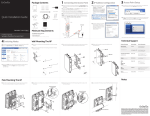
Business Solution User Manual EGS5110P version 1.0 8-Port Gigabit PoE+ Smart Switch with 2 Gigabit SFP TABLE OF CONTENTS TABLE OF CONTENTS Conventions iv Copyright vi Getting Started Overview 1-1 EGS5110P 1-1 Management Interface 1-2 Connecting the Device to the Network 1-2 Discovery in a Network with a DHCP Server 1-2 Discovery in a Network without a DHCP Server 1-3 Web Access 1-3 Management System 2-1 Summary 2-1 IP Setting 2-2 Port Settings 2-3 PoE Management 2-4 PoE Port Configuration 2-5 Cable Diagnostics 2-6 Password 2-7 Zero Configuration 2-8 I TABLE OF CONTENTS L2 Feature 2-9 Port Trunking 2-9 IGMP Snooping 2-11 Multicast Group List 2-12 Port Mirroring 2-13 Loopback Detection 2-14 Static MAC Address 2-15 Dynamic Address List 2-16 VLAN 2-17 802.1Q 2-17 Adding, Editing, and Deleting Items in the list . . . . . . . . . . . . . . .2-18 PVID 2-21 Port-based VLAN 2-22 Adding, Editing, and Deleting Items in the list . . . . . . . . . . . . . . .2-23 QoS 2-25 802.1p Default Priority 2-25 CoS Priority Class 2-26 Storm Control 2-27 Bandwidth Control 2-28 Maintenance Maintenance 3-1 Saving Configuration 3-1 Upgrading 3-2 Resetting 3-2 Rebooting 3-3 Logging Out 3-3 II TABLE OF CONTENTS Appendix A Federal Communication Commission Interference Statement A-4 Appendix B Industry Canada Statement B-5 Appendix C WorldWide Technical Support C-6 III CONVENTIONS Conventions The following conventions are used to give the user additional information about specific procedures or content. It is important to pay attention to these conventions as they provide information to prevent damage to\ equipment or personal injury. General Conventions The following general conventions are used in this document. ! ! CAUTION! CAUTIONS APPEAR BEFORE THE TEXT IT REFERENCES. CAUTIONS APPEAR IN CAPITAL LETTERS TO EMPHASIZE THAT THE MESSAGE CONTAINS VITAL HEALTH AND SAFETY INFORMATION. WARNING! Warning information appears before the text it references to emphasize that the content may prevent damage to the device or equipment. Important: Indicates information that is important to know for the proper completion of a procedure, choice of an option, or completing a task. Note: Indicates additional information that is relevant to the current process or procedure. N/A: Indicates that a component or a procedure is not applicable to this model. Prerequisite: Indicates a requirement that must be addressed before proceeding with the current function or procedure. IV CONVENTIONS Typographical Conventions The following typographical conventions are used in this document: Italics Indicates book titles, directory names, file names, path names, and program/process names. Constant width Indicates computer output shown on a computer screen, including menus, prompts, responses to input, and error messages. Constant width bold Indicates commands lines as entered on the computer. Variables contained within user input are shown in angle brackets (< >). Bold Indicates keyboard keys that are pressed by the user. V COPYRIGHT Copyright This user guide and its content is copyright of © Company Name, 2013. All rights reserved. Any redistribution or reproduction in part or in whole in any form is prohibited. Do not distribute, transmit, store in any form of electronic retrieval system or commercially exploit the content without the expressed written permission of Company Name. VI Getting Started Chapter 1 GETTING STARTED OVERVIEW 1.1 Overview The EGS Smart Switch Series are smart switch devices specially tailored for access points and IP surveillance applications. The Smart Switch Series provide simple, yet, powerful PoE manageability with features such as: Full IEEE802.3AT/AF ports, internal power supply, PoE port management, loopback detection, and IGMP snooping. The following section provides an overview of the external device views. It also provides a brief description of the ports and LEDs. 1.1.1 EGS5110P AB C D E F G H I Figure 1-1 Front Panel FRONT PANEL A Power LED DESCRIPTION OFF = The device is not powered on. ON = The device is receiving power. OFF = The maximum power draw by other devices has not been reached. B PoE Maximum LED C System Fault LED D Factory Reset Press this to reset the device to factory default settings E LED Mode Selector Press this to change between LAN and PoE mode. F PoE Mode LED G LAN Mode LED H RJ-45 LAN Ports 10/100/1000Mbps RJ-45 LAN ports. I SFP Ports Small form factor pluggable ports. ON = The maximum power draw by connected devices has been reached. OFF = The device is operating. ON = A system fault is detected. OFF = The device is not in PoE mode. ON = The device is in PoE mode. OFF = The device is not in LAN mode. ON = The device is in LAN mode. 1-1 GETTING STARTED OVERVIEW 1.2 Management Interface The company name EGS5110P features an embedded web and management interface for the monitoring of your device. The interface is designed to help you configure basic and advanced features to help you improve switch efficiency and overall network performance. Through the Web interface you can monitor, configure, and control your switch remotely using a browser 1.3 Connecting the Device to the Network 1.3.1 Discovery in a Network with a DHCP Server Use this procedure to setup the device within a network using the DHCP function. 1. Connect one end of an Ethernet cable (RJ-45) to the LAN port of your PC and the other end to the device. 2. Connect the power cable to the device and turn it on. 3. On the PC connected to the device, change the PC’s IP settings with those of the device: 192.168.0.0/24 subnet. 4. Open a Web browser on the PC and enter the following address (default): http:/ /192.168.0.239. 5. On the login screen, use the following information. Password: password 6. Once logged in, click System -> IP Setting and select DHCP. 7. Click Apply to save the settings. 8. Connect the device to your network (DHCP enabled). 9. On the DHCP server, find and write down the IP address allocated to the device. Use this IP address to access the management interface. 1-2 GETTING STARTED OVERVIEW 1.3.2 Discovery in a Network without a DHCP Server Use this procedure to setup the device within a network requiring a static IP address. 1. Connect one end of an Ethernet cable (RJ-45) to the LAN port of your PC and the other end to the device. 2. Connect the power cable to the device and turn it on. 3. On the PC connected to the device, change the PC’s IP settings with those of the device: 192.168.0.0/24 subnet. 4. Open a Web browser on the PC and enter the following address (default): http:/ /192.168.0.239. 5. On the login screen, use the following information. Password: password 6. Once logged in, click System -> IP Setting and select Static IP under the System Setting menu to configure the IP settings of the management interface. 7. Enter the IP address, subnet mask and gateway as given by your system administrator. 8. Click Apply. 9. Connect the device to your network. 1.4 Web Access Use this procedure to access the management interface through a Web browser for device configuration. 1. Open a Web browser on your PC and enter the following address (default): http://192.168.0.239. 2. On the login screen, use the following information. Password: password 1-3 Management Chapter 2 MANAGEMENT SYSTEM 2.1 System The System menu enables management IP address and password to be configured and individual port speed and Power over Ethernet (PoE) configuration and cable diagnostics to be performed. This chapter describes these functions. 2.1.1 Summary Click the Summary link under the System menu to see important system information such as firmware version and chassis MAC address. LABEL DESCRIPTION Name This shows the model number. FW version This shows the currently running. Serial Number This shows the serial number. Base MAC address This shows the chassis MAC address. IP address This shows the IP address of the management interface. Gateway This shows the IP address of the gateway to other subnets or networks. System up time This shows the elapsed time since the last reboot. 2-1 MANAGEMENT IP SETTING 2.1.2 IP Setting Click the IP Setting link under the System menu to configure the IP settings of your device. This IP address is also the address for the management Web interface. To access the page, click System -> IP Setting. LABEL DESCRIPTION Type Use this to configure the device to use static IP settings or get its settings via Dynamic Host Configuration Protocol (DHCP). IP address Use this to configure the IP address of the management interface. Subnet mask Use this to configure the subnet mask of the management interface. Gateway Use this to configure the IP address of a router on the same subnet as the management interface that connects to other subnets. Apply Click this to apply settings. 2-2 MANAGEMENT PORT SETTINGS 2.1.3 Port Settings Click the Port Setting link under the System menu to configure the speed and duplex settings of each port. To access the page, click System -> Port Setting. LABEL DESCRIPTION Port This shows the port number. Trunk This show which trunk the port belongs to. For details on configuring a trunk, refer to “Port Trunking” on page 2-9. Link This shows whether the port is up or down at the physical layer. Speed Select one or more ports, select the speed and duplex settings from the drop-down box and click apply to configure port speed and duplex settings. Apply Click this to apply settings. 2-3 MANAGEMENT POE MANAGEMENT 2.1.4 PoE Management Ports 1~8 on the EGS5110P are IEEE802.3at compliant ports. Each port is capable of delivering up to 30W and a power budget of 124W for uninterrupted PoE use. To access the page, click System -> PoE Management. LABEL DESCRIPTION Total Power Budget Use this to configure the total power that can be supplied over all Ethernet ports. Current Power Used This shows how much power is being used by connected devices. Apply Click this to apply settings. 2-4 MANAGEMENT POE PORT CONFIGURATION 2.1.5 PoE Port Configuration You can use the PoE Port Configuration page to view PoE power information and to configure the power settings. To access the page, click System -> PoE Port Configuration. LABEL DESCRIPTION Port This shows the port number. Priority Use this to configure which ports get power first. Class Use this to configure whether the power class is negotiated within a userdefined power limit or not. Use this to configure the maximum power that is supplied over a port. User Power Limit Note: The user power limit can only be implemented when the Class value is set to User-Defined. State Use this to enable or disable power over Ethernet on a port. Status Apply Click this to apply settings. 2-5 MANAGEMENT CABLE DIAGNOSTICS 2.1.6 Cable Diagnostics You can use the Cable Diagnostics page to perform a diagnostic on each cable connected to the device ports. The cable status and length are displayed after a test is performed. To access the page, click System -> Cable Diagnostics. LABEL DESCRIPTION Port Use this to select the port number. Status This shows the state of the cable. Cable Length This shows the cable length in meters. Test Click this to start the test. 2-6 MANAGEMENT PASSWORD 2.1.7 Password Use the Password page to change your current login password. To access the page, click System -> Password. LABEL DESCRIPTION Password This shows the current password. New Password Enter a new password here. Confirm Enter the new password again here. Apply Click this to apply settings. 2-7 MANAGEMENT ZERO CONFIGURATION 2.1.8 Zero Configuration Use the Zero Configuration page to enable devices on your network to automatically configure themselves and be discovered without further configuration. The Bonjour service is enabled or disabled through the Zero Configuration page. To access the page, click System -> Zero configuration. LABEL DESCRIPTION Bonjour Use this to enable or disable auto configuration through the Bonjour protocol. Apply Click this to apply settings. 2-8 MANAGEMENT L2 FEATURE 2.2 L2 Feature The L2 Feature menu enables port trunking, control of multicast traffic flooding, port mirroring, cabling loop detection and MAC address table management. This chapter describes these functions. 2.2.1 Port Trunking Use the Port Trunking page to link multiple cables/ports in a parallel connection to increase the throughput beyond that of a single connection. The linked cables/ports can also act to create link redundancy. Note: You must enable trunk mode before you can add a port to a trunk group. To access the page, click L2 Feature -> Port Trunking. LABEL Group DESCRIPTION This shows the trunk number. 2-9 MANAGEMENT PORT TRUNKING LABEL DESCRIPTION Click and then click here to enable or disable a trunk. You set the mode to Enabled before you can edit the member ports. Mode LABEL Member Ports Click the Apply button them. DESCRIPTION Click and then click here to define which ports are members of a trunk. to accept the changes or the Cancel button 2-10 to discard MANAGEMENT IGMP SNOOPING 2.2.2 IGMP Snooping Use the IGMP Snooping page to enable or disable this function. This feature allows the device to listen in on the Internet Group Management Protocol (IGMP) conversations between hosts and routers to map out IP multicast streams. The device can limit flooding of traffic to IGMP designated ports. To access the page, click L2 Feature -> IGMP Snooping. LABEL DESCRIPTION Setting Use this to enable or disable IGMP snooping. Apply Click this to apply settings. 2-11 MANAGEMENT MULTICAST GROUP LIST 2.2.3 Multicast Group List The Multicast Group List page displays a list of ports with the Multicast designation. To access the page, click L2 Feature -> Multicast Group List. LABEL DESCRIPTION Group IP This shows the multicast IP address of the group. VID This shows the VLAN ID that the multicast group is operating over. Member Ports This shows which ports have IGMP members on them. 2-12 MANAGEMENT PORT MIRRORING 2.2.4 Port Mirroring You can use the Port Mirroring page to view and configure source and destination ports to define port mirroring sessions. In this way, network packets from one port can be copied and sent to a monitoring connection on a different port. Both inbound or outbound traffic (or both) can be mirrored on the device. To access the page, click L2 Feature -> Port Mirroring. LABEL DESCRIPTION Direction Use this to select whether received, transmitted or bidirectional traffic is mirrored. Source Port Click this to select the ports from which traffic is mirrored. Destination Port Use this to select the port to which traffic is mirrored. Apply Click this to apply settings. 2-13 MANAGEMENT LOOPBACK DETECTION 2.2.5 Loopback Detection When Spanning Tree Protocol (STP) is not enabled in the network, the Loopback Detection function can be used to detect the loop created by a specific port. Click the Loopback Detection link under the L2 Feature menu to configure loop detection for loops created by a specified port. For users connecting hubs or unmanaged switches, the Loopback Detection function shuts a port when packets are sent and received from the same port--a loopback effect. The port is automatically unlocked after the recovery period times out. LABEL DESCRIPTION Time Interval Enter how long traffic is allowed to flow over a cabling loop before the looped ports are shut down. Recovery Time Enter how long after ports are shut down before they are automatically reenabled. Apply Click this to apply the settings to all ports. 2-14 MANAGEMENT STATIC MAC ADDRESS 2.2.6 Static MAC Address Click the Static MAC Address link under the L2 Feature menu to edit the MAC address table. LABEL DESCRIPTION Index This shows the internal index for this MAC address table entry. Port Click this to select the port from which traffic to a destination MAC address will be sent. VID Click this to select the VLAN ID that traffic to a destination MAC address will be sent. MAC Address Click this select the destination MAC address that will be matched to traffic. Add Click this to add a new entry to the MAC address table. Edit Click this to edit an existing entry listed in the MAC address table. Delete Click this to delete an existing entry listed in the MAC address table. 2-15 MANAGEMENT DYNAMIC ADDRESS LIST 2.2.7 Dynamic Address List Click the Dynamic Address List link under the L2 Feature menu to show the MAC address table. LABEL DESCRIPTION Index This shows the internal index for this MAC address table entry. Port This shows the port from which traffic to a destination MAC address is sent. VID This shows the VLAN ID that traffic to a destination MAC address is sent. MAC Address This shows the destination MAC address that is matched to traffic. 2-16 MANAGEMENT VLAN 2.3 VLAN The VLAN menu enables configuration of 802.1Q VLANs or port-based VLANs. This chapter describes these functions. 2.3.1 802.1Q Click the 802.1Q link under the VLAN menu to configure which egress ports add 802.1Q tags to traffic. Important: Port-based VLAN and 802.1Q VLAN are mutually exclusive. If you enable port-based VLAN, then 802.1Q VLAN is disabled. Note: All ports with a VID of 1 are assigned to the default VLAN. LABEL DESCRIPTION VID This shows the 802.1Q tag that is added to egress traffic on these ports. Name Defines the name of the VLAN. Tagged Ports Shows the egress ports that tag traffic. Selecting tagged ports removes them from the Untagged Ports field. Untagged Ports Shows the egress ports that don’t tag traffic. Selecting untagged ports removes them from the Tagged Ports field. 2-17 MANAGEMENT ADDING, EDITING, AND DELETING ITEMS IN THE LIST LABEL Enabled DESCRIPTION Click this to enable 802.1Q VLANs. This feature is enabled by default. Adding, Editing, and Deleting Items in the list To add an item to the 802.1Q list, follow these steps: 1. Click the Add button . 2. Enter the VID and name values in the VID and Name text boxes. 3. Click the Tagged Ports text box to show the tagged ports dialog box. 4. Click a radio button in the tagged ports row to select a port. 5. Click the Untagged Ports text box to show the untagged ports dialog box. 6. Click a radio button in the untagged ports row to select a port. 2-18 MANAGEMENT ADDING, EDITING, AND DELETING ITEMS IN THE LIST 7. Click Confirm to accept the changes or Cancel discard them. To edit an item in the 802.1Q list, follow these steps: 1. Click the edit button . 2. Enter the VID and name values in the VID and Name text boxes. 3. Click the Tagged Ports text box to show the tagged ports dialog box. 4. Click a radio button in the tagged ports row to select a port. 5. Click the Untagged Ports text box to show the untagged ports dialog box. 6. Click a radio button in the untagged ports row to select a port. 7. Click Confirm to accept the changes or Cancel discard them. 2-19 MANAGEMENT ADDING, EDITING, AND DELETING ITEMS IN THE LIST To delete an item in the 802.1Q list, follow these steps: 1. Click the delete button is displayed. in the row you want to remove. A confirmation dialog 2. Click OK to continue or Cancel to abort the changes. 2-20 MANAGEMENT PVID 2.3.2 PVID Click the PVID link under the VLAN menu to tag outgoing, untagged packets and to filter incoming packets. Note: To enable PVID functionality the following requiremnents must be met: All ports must have a defined PVID. If no other value is specified, the default VLAN PVID is used. If you want to change the port’s default PVID, you must first create a VLAN that includes the port as a member. LABEL DESCRIPTION Port This shows the port number. Trunk This shows the trunk number (if any are defined for this port). PVID Select one or more ports and then click here to select a PVID. Apply Click this to apply settings. 2-21 MANAGEMENT PORT-BASED VLAN 2.3.3 Port-based VLAN Click the Port-based VLAN link under the VLAN menu to enable and show port-based VLANs. Important: Port-based VLAN and 802.1Q VLAN are mutually exclusive. If you enable port-based VLAN, then 802.1Q VLAN is disabled. LABEL DESCRIPTION VID This shows the VLAN ID of the port-based VLAN. Name This shows the name of the port-based VLAN. Member Ports This shows which ports belong to this port-based VLAN. LABEL Enabled DESCRIPTION Click this to enable port-based VLANs. This feature must be enabled to configure a port-based VLAN. 2-22 MANAGEMENT ADDING, EDITING, AND DELETING ITEMS IN THE LIST Adding, Editing, and Deleting Items in the list To add an item to the 802.1Q list, follow these steps: 1. Click the Add button . 2. Enter the VID and name values in the VID and Name text boxes. 3. Click the Member Ports text box to show the ports dialog box. 4. Click a check box in the member ports row to select a port. 5. Click Confirm to accept the changes or Cancel discard them. 2-23 MANAGEMENT ADDING, EDITING, AND DELETING ITEMS IN THE LIST To edit an item in the 802.1Q list, follow these steps: 1. Click the edit button . 2. Enter the VID and name values in the VID and Name text boxes. 3. Click the Member Ports text box to show the member ports dialog box. 4. Click a check box in the member ports row to select a port. 5. Click Confirm to accept the changes or Cancel discard them. To delete an item in the 802.1Q list, follow these steps: 1. Click the delete button is displayed. in the row you want to remove. A confirmation dialog 2. Click OK to continue or Cancel to abort the changes. 2-24 MANAGEMENT QOS 2.4 QoS The QoS menu enables traffic to be prioritized, excessive broadcast and multicast traffic to be avoided and overall bandwidth to be limited on a port-by-port basis. This chapter describes these functions. 2.4.1 802.1p Default Priority Click the 802.1p Default Priority link under the QoS menu to define which 802.1p/Q priority is applied to untagged ingress traffic. The priority level is from 0 to 7. EGS5110P supports four class quality levels: low, normal, medium, and high. To find out how to map the priority value to one of the four classes, refer to “CoS Priority Class” on page 2-26. LABEL DESCRIPTION Port This shows the port number. Trunk This shows the trunk number (if any are defined for this port). Ports assigned to the same trunk group are assigned the same priority level. Priority Select the priority for untagged traffic arriving on this port. Apply Click this to apply settings. 2-25 MANAGEMENT COS PRIORITY CLASS 2.4.2 CoS Priority Class Click the CoS Priority Class link under the QoS menu to define which 802.1p/Q priority class (low, normal, medium, or high) is applied to untagged ingress traffic. LABEL DESCRIPTION Priority This shows the Priority Code Point (PCP) that matches ingress traffic. Class Select the Class of Service (CoS) that is applied to traffic. Traffic classified as High CoS are sent first. Apply Click this to apply settings. 2-26 MANAGEMENT STORM CONTROL 2.4.3 Storm Control The Storm Control feature provides the ability to control the receive rate of broadcast, multicast, and unknown unicast packets. Click the Storm Control link under the QoS menu to limit excessive flooding caused by a packet storm. LABEL DESCRIPTION Type Use this to select which type of traffic will be limited. Port Threshold Unknown Unicast: If the rate of unknown L2 unicast (destination lookup failure) traffic ingressing on an interface increases beyond the configured threshold, the traffic will be dropped. Multicast: If the rate of L2 multicast traffic ingressing on an interface increases beyond the configured threshold, the traffic will be dropped. Broadcast: If the rate of L2 broadcast traffic ingressing on an interface increases beyond the configured threshold, the traffic will be dropped. Use this to configure how many packets per second are allowed to flood. 2-27 MANAGEMENT BANDWIDTH CONTROL 2.4.4 Bandwidth Control Click the Bandwidth Control link under the QoS menu to define how much traffic can pass through a port. LABEL DESCRIPTION Port This shows the port number. Trunk This shows the trunk number (if any are defined for this port). Tx Use this to configure the maximum bandwidth this port sends out. Rx Use this to configure the maximum bandwidth this port accepts. Apply Click this to apply settings. 2-28 Maintenance Chapter 3 MAINTENANCE MAINTENANCE 3.1 Maintenance Maintenance functions are available from the maintenance bar. Maintenance functions include: Saving Configuration settings, Upgrading firmware, Resetting the configuration to factory defaults, Rebooting the device, and Logging Out of the interface. The following is the Maintenance menu bar. Figure 3-1 Maintenance Bar 3.1.1 Saving Configuration Important: You must save any setting changes before rebooting. Failing to save results in loss of new configuration changes. Follow this procedure to save the configuration, so it will survive a reboot. 1. Click to begin saving the configuration settings. 2. Click OK. 3-1 MAINTENANCE MAINTENANCE 3.1.2 Upgrading ! WARNING! Backup your configuration information before upgrading to prevent loss of setting information. Follow this procedure to upgrade the firmware. 1. Click to start upgrading. 2. Click Choose File. A window opens, browse to the location of your new firmware. 3. Select the new firmware file and click OK. 4. A prompt displays to confirm the firmware upgrade. Click OK and follow the onscreen instructions to complete the firmware upgrade. Note: The Upgrade process may require a few minutes to complete. 3.1.3 Resetting ! WARNING! The Reset function will delete all configuration information from the current device. Backup your information before starting this procedure. Follow this procedure to reset the device to factory default settings. 1. Click to start the rest process. 2. A prompt displays, click OK to confirm the reset or Cancel to quit the procedure. 3-2 MAINTENANCE MAINTENANCE 3.1.4 Rebooting Follow this procedure to reboot the device. 1. Click to start the reboot process. 2. A prompt displays, click OK to confirm the reboot or Cancel to quite the procedure. 3.1.5 Logging Out Follow this procedure to log out the current profile from the user interface. 1. Click to log out of the menu. 2. A prompt displays, click OK to confirm the logout or Cancel to quit the procedure. 3-3 APPENDIX FEDERAL COMMUNICATION COMMISSION INTERFER- Appendix A Federal Communication Commission Interference Statement This equipment has been tested and found to comply with the limits for a Class B digital device, pursuant to Part 15 of the FCC Rules. These limits are designed to provide reasonable protection against harmful interference in a residential installation. This equipment generates uses and can radiate radio frequency energy and, if not installed and used in accordance with the instructions, may cause harmful interference to radio communications. However, there is no guarantee that interference will not occur in a particular installation. If this equipment does cause harmful interference to radio or television reception, which can be determined by turning the equipment off and on, the user is encouraged to try to correct the interference by one of the following measures: Reorient or relocate the receiving antenna. Increase the separation between the equipment and receiver. Connect the equipment into an outlet on a circuit different from that to which the receiver is connected. Consult the dealer or an experienced radio/TV technician for help. ! WARNING! Any changes or modifications not expressly approved by the party responsible for compliance could void the user's authority to operate this equipment. This device complies with Part 15 of the FCC Rules. Operation is subject to the following two conditions: (1) This device may not cause harmful interference, and (2) this device must accept any interference received, including interference that may cause undesired operation. FCC Radiation Exposure Statement Important: This equipment complies with FCC radiation exposure limits set forth for an uncontrolled environment. This device complies with FCC RF Exposure limits set forth for an uncontrolled environment, under 47 CFR 2.1093 paragraph (d)(2). This transmitter must not be co-located or operating in conjunction with any other antenna or transmitter. A-4 APPENDIX INDUSTRY CANADA STATEMENT Appendix B Industry Canada Statement This device complies with RSS-210 of the Industry Canada Rules. Operation is subject to the following two conditions: (1) This device may not cause harmful interference, and (2) this device must accept any interference received, including interference that may cause undesired operation. Ce dispositif est conforme à la norme CNR-210 d'Industrie Canada applicable aux appareils radio exempts de licence. Son fonctionnement est sujet aux deux conditions suivantes: (1) le dispositif ne doit pas produire de brouillage préjudiciable, et (2) ce dispositif doit accepter tout brouillage reçu, y compris un brouillage susceptible de provoquer un fonctionnement indésirable. Important: Radiation Exposure Statement: This equipment complies with IC radiation exposure limits set forth for an uncontrolled environment. This equipment should be installed and operated with minimum distance 20cm between the radiator & your body. Déclaration d'exposition aux radiations: Cet équipement est conforme aux limites d'exposition aux rayonnements IC établies pour un environnement non contrôlé. Cet équipement doit être installé et utilisé avec un minimum de 20 cm de distance entre la source de rayonnement et votre corps. B-5 APPENDIX WORLDWIDE TECHNICAL SUPPORT Appendix C WorldWide Technical Support REGION/COUNTRY OF PURCHASE SERVICE CENTRE CANADA Canada LOS ANGELES, USA USA MIAMI, USA SERVICE INFORMATION web site www.engeniuscanada.com email [email protected] contact numbers Toll Free: (+1) 888-397-2788 hours of operation Monday - Friday web site www.engeniustech.com email [email protected] contact numbers Toll Free: (+1) 888-735-7888 hours of operation Monday - Friday 9:00AM to 5:30PM EST (GMT-5) Local: (+1) 714-432-8668 8:00 AM to 4:30 PM PST (GMT-8) [ES] es.engeniustech.com web site [PT] pg.engeniustech.com email Mexico, Central and Southern America Local: (+1) 905-940-8181 [email protected] Miami: (+1) 305-887-7378 contact numbers Sao Paulo, Brazil: (+55)11-3957-0303 D.F., Mexico:(+52)55-1163-8894 NETHERLANDS Europe hours of operation Monday - Friday web site www.engeniusnetworks.eu email [email protected] contact numbers (+31) 40-8200-887 hours of operation C-6 8:00 AM to 5:30PM EST (GMT-5) Monday - Friday 9:00 AM - 5:00 PM (GMT+1) APPENDIX WORLDWIDE TECHNICAL SUPPORT REGION/COUNTRY OF PURCHASE SERVICE CENTRE Africa, Middle East, Russia, CIS/ Armenia, Azerbaijan, Belarus, Georgia, Kazakhstan, Kyrgyzstan, Moldova, Tajikistan, Turkmenistan, Ukraine, Uzbekistan, Turkey, Afghanistan, Pakistan, Bangladesh, Maldives, Nepal, Bhutan, Sri Lanka DUBAI, UAE Singapore, Cambodia, Indonesia, Malaysia, Thailand, Philippines, Vietnam, China, Hong Kong, Korea, India, South Africa, Oceania Others SERVICE INFORMATION web site www.engenius-me.com email [email protected] Toll Free: U.A.E.: 800-EnGenius contact numbers 800-364-364-87 General: (+971) 4357-5599 hours of operation SINGAPORE TAIWAN, R.O.C. Sunday - Thursday 9:00 AM - 6:00 PM (GMT+4) web site www.engeniustech.com.sg/ e_warranty_form email [email protected] contact numbers Toll Free: hours of operation Monday - Friday web site www.engeniusnetworks.com email [email protected] Singapore: 1800-364-3648 9:00 AM - 6:00 PM (GMT+8) Note: * Service hours are based on the local time of the service center. * Please visit the website for the latest information about customer service. C-7