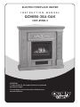
1
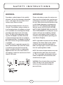
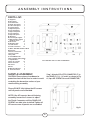
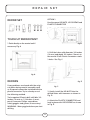
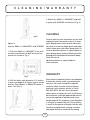
ELECTRIC FIREPLACE HEATER
INSTRUCTION MANUAL
QCM650-38A-OAK
NDF-65NB-3
ATTENTION:
1. Find a location for the fireplace heater that is protected
from direct sunlight.
2. Do not plug the unit into the power outlet before you
read all instructions.
SAFETY INSTRUCTIONS
IMPORTANT SAFETY INSTRUCTIONS
WHEN USING ELECTRICAL APPLIANCES, BASIC
PRECAUTIONS SHOULD ALWAYS BE FOLLOWED TO REDUCE
THE RISK OF FIRE, ELECTRIC SHOCK, AND INJURY TO
PERSONS, INCLUDI NG THE FOLLOWING:
8) Do not run cord under carpeting. Do not
cover cord with throw rugs, runners, or
similar coverings. Arrange cord away from
traffic area and where it will not be tripped
over.
1) Read all instructions before using this
electric fireplace heater.
2) This electric fireplace heater is hot when
in use. To avoid burns, do not let bare skin
touch hot surfaces. The grill directly in front
of the heater outlet becomes hot during
heater operation. Keep combustible materials, such as furniture, pillows, bedding,
papers, clothes, and curtains at least 3 feet
(0.9 m) away from the front of the unit and
keep them away from the sides and rear.
9) To disconnect fireplace, turn controls to
off, then remove plug from outlet.
10) Connect to properly grounded outlets
only.
11) Do not insert or allow foreign objects to
enter any ventilation or exhaust opening as
this may cause an electric shock or fire, or
damage the heater.
3) Extreme caution is necessary when
any heater is used by or near children or
invalids and whenever the fireplace is left
operating and unattended.
12) To prevent a possible fire, do not block
air intakes or exhaust in any manner. Do
not use on soft surfaces, like a bed, where
openings may become blocked.
4) Always unplug fireplace when not in use.
5) Do not operate any electric fireplace with
a damaged cord or plug or after the heater
malfunctions, has been dropped or damaged in any manner.
6) Do not use outdoors.
13) A heater has hot and arcing or sparking
parts inside. Do not use it in areas where
gasoline, paint, or flammable liquids are
used or stored.
7) This electric fireplace heater is not intended for use in bathrooms, laundry areas
and similar indoor locations. Never locate
heater where it may fall into a bathtub or
other water container.
14) Use this fireplace heater only as
described in this manual. Any other use
not recommended by the manufacturer
may cause fire, electric shock, or injury to
persons.
2
SAFETY INSTRUCTIONS
15) Avoid the use of an extension cord
because the extension cord may overheat
and cause a risk of fire. However, if you have
to use an extension cord, the cord shall be
No.14 AWG minimum size and rated not
less than 1875 watts. The extension cord
shall be a 3 wire cord with a grounding type
cord and plug connector.
16) Do not plug this product into a receptacle
controlled by a wall switch or dimmer.
17) When storing or transporting the unit
and cord, keep in a dry place, free from
excessive vibration and store so as to
avoid damage.
CAUTION
If you use this heater in conjunction with
a thermal control, a program controller,
a timer or any other device that switches
the heater on automatically, remember to
observe all safety warnings at all times. The
stove heater has safety overheat protection.
If the overheat protection trips, unplug the
power cord from the receptacle. It should
reset automatically after 5 minutes.
SAVE THESE INSTRUCTIONS
FOR FUTURE USE.
3
SAFETY INSTRUCTIONS
WARNING:
IMPORTANT
Procedures and techniques if not carefully
followed - will result in damage to the equipment. - will expose the user to the risk of
serious injury, illness or death.
Please note when you open the carton carefully check the unit and make sure there are
no damages. If you have any problems with
the unit, with how the various functions work
or with hidden damages or missing parts
please call 1-800-459-4409 (EST) immediately for service. NOTE: DO NOT RETURN
UNIT TO THE STORE BEFORE CALLING THE
TOLL FREE NUMBER. Do not dispose of your
cartons until you are completely satisfied
with your new fireplace heater. Read all instructions thoroughly before operating your
new Electric Fireplace.
This electric fireplace heater is for use on
120 volts. The cord has a plug as shown at
A in illustration below. An adapter as shown
at C is available for connecting three-blade
grounding-type plugs to two-slot receptacles. The green grounding plug extending from the adapter must be connected
to a permanent ground such as a properly
grounded outlet box. The adapter should not
be used if a three-slot grounded receptacle
is available.
A 15 AMP circuit is required to operate this
heater. If the breaker trips when the heater
is used then you may need to move the
heater to another location or unplug other
appliances that are on the same circuit. If
you require an extension cord use one that is
rated at 1875 watts.
NOTE: Light bulbs may become loose during
shipping. If the flame effect is dim or does
not work, please check that light bulb or
bulbs are finger tight in socket. See instructions for replacing bulb or bulbs.
NOTE: The electric fireplace heater may emit
a slight harmless odor when first turned
on. This is caused by activating the internal
heater components for the first time and
should not occur again.
WARNING: Do not load articles more than
40 lbs (18.2kg) on the corner drop leaf,
which may cause product damage or
personal injury.
4
A S S E M B LY I N S T R U C T I O N S
PARTS LIST:
A) Top panel 1
B) Base panel 1
C) Decorative bar
1
D) Upper-front panel 1
E) Lower-front panel 1
F) Left front panel 1
G) Right front panel
1
H) Left small panel 1
J) Right small panel 1
K) Left side panel 1
L) Right side panel 1
M) Drop leaf 1
N) Left Triangle support 1
P) Right Triangle support 1
Fireplace insert 1
Q) KD screws 60
R) Mounting clips 3
S) Small screws 6
T) Plastic connectors 16
U) WALL ANCHOR SAFETY CABLE
Wall anchor 1
Screw for wall anchor 1
Screw for mantle 1
Safety cable 1
V) SELF REPAIR SET
Touch-up repair paint (bottle)
L shape bracket 8
Screws for L shape 32
Plastic connector 1
KD screws 3
KD nuts 3
TOOL REQUIRED: PHILLIPS HEAD SCREWDRIVER
W) Mounting bracket 2
X) Short KD screws 3
MANTLE ASSEMBLY:
Step 1: Attach all PLASTIC CONNECTOR (T) to
the PANELS (C, H, J, K and L) as shown in Fig.
A. (2pcs KD SCREWS for each CONNECTOR)
CAUTION: Place a piece of cardboard or
protective sheet on the floor in order to avoid
scratching the decorative surface of your
mantle during assembly.
Please DO NOT fully tighten the KD screws
until all panels are assembled.
NOTE: If the KD screw(s) do not fit during
assembly, loosen the 2 screws to adjust
the Plastic Connector until the PANEL/KD
SCREWS are able to be installed. Tighten all
KD screws once all panels are assembled.
fig. A
5
A S S E M B LY I N S T R U C T I O N S
Step 2: Attach the LEFT SMALL PANEL (H)
to the LEFT FRONT PANEL(F) with 2 KD
SCREWS. Attach the RIGHT SMALL PANEL
(J) to the RIGHT FRONT PANEL(G) with 2 KD
SCREWS. See fig. B
fig. D
Step 5: Place the LOWER FRONT PANEL (E) in
between the lower sections of LEFT & RIGHT
SMALL PANEL (H and J) and attach with 2 KD
SCREWS (1 screw each side). See Fig. E
fig. B
Step 3: Attach the LEFT SIDE PANEL (K) to the
LEFT FRONT PANEL (F) with 3 KD SCREWS.
Attach the RIGHT SIDE PANEL (L) to the
RIGHT FRONT PANEL (G) with 3 KD SCREWS.
See fig. C
fig. E
Step 6: Place the UPPER FRONT PANEL (D) in
between the upper section of LEFT & RIGHT
FRONT PANELS (F and G) and attach with
4 KD SCREWS (2 screws each side). See Fig. F
fig. C
Step 4: Attach the LEFT (K, F, H) and RIGHT
(L, G, J) SIDE PANELS to the BASE PANEL (B)
using 4 KD SCREWS (2 screws on each side).
See Fig. D
fig. F
6
A S S E M B LY I N S T R U C T I O N S
Step 10: Install the TOP PANEL (A) to the unit
as shown with 4 KD SCREWS. See Fig. J
Step 7: Attach the DECORATIVE BAR (C) over
the UPPER FRONT PANEL (D) and attach
with 2 KD SCREWS (1 screws each side).
See Fig. G
fig. J
fig. G
Step 11: Tighten all SCREWS. Fig. K
Step 8: Attach the LEFT TRIANGLE SUPPORT (N) on the LEFT SIDE PANEL (K).
Attach the RIGHT TRIANGLE SUPPORT (P)
on the RIGHT SIDE PANEL (L). See Fig. H
fig. K
FIREPLACE INSERT
INSTALLATION:
fig. H
The fireplace insert can be installed after the
mantle has been fully assembled.
Step 9: Attach the DROP LEAF (M) on the
TOP PANEL (A) and attach with 6 SMALL
SCREWS. See Fig. I
WARNING: Make sure the fireplace insert
controls are in the OFF position and the unit
is NOT plugged in.
Step 1: Place the INSERT on the floor, directly in front of the MANTLE. (The backs of
both the mantle and insert should be facing
the same direction.)
Step 2: Carefully lift the insert into the
fig. I
7
A S S E M B LY I N S T R U C T I O N S
mantle opening. The front of the INSERT
should be flush with the front of the mantle.
and gently tap until the flange on the anchor
is against the wall surface.
Step 3: Once the INSERT is in place, attach
3 MOUNTING CLIPS (R) on the top of the
INSERT and lock the insert in place with 3
SHORT KD SCREWS (X). See fig. L
2. Position the back edge of the mantle close
to the wall.
3. Attach the SAFETY CABLE to the mantle
using the SCREW FOR MANTLE. See figure
M or N.
4. Use the SCREW FOR WALL to attach the
other end of SAFETY CABLE to the wall.
5. Make sure all screws are tight.
fig. L
Step 4: Attach 2 MOUNTING BRACKET (W) to
the bottom with 2 KD SCREWS. See fig. L
Step 5: Move assembled unit to desired
location. Unit should not be positioned in
area exposed to direct sunlight.
WALL ANCHOR
SAFETY CABLE
fig. M
The use of WALL ANCHOR SAFETY CABLE
is highly recommended in order to reduce
the risk of the fireplace being tipped over
accidentally. WARNING: This CABLE may
reduce possible risk of injury if the fireplace
is improperly handled, but is not a substitute for proper adult supervision. Children
should not be left unattended near any
heater.
fig. N
1. Drill a 5/16” (8mm) hole in the wall. Insert
the PLASTIC WALL ANCHOR into the hole
8
O P E R A T I O N
ON/OFF: Press this button for main power
and flame effect. The indicator light will turn
on. See below for other control switches.
After reading complete instructions, confirm
all controls on fireplace are in the OFF position. Plug the fireplace into a 15AMP/120Volt
outlet. If the cord does not reach, you may
use an extension cord rated for a minimum
of 1875 WATTS. Once the fireplace insert
has been properly connected to a grounded
electrical outlet, it is ready to operate.
750W: For low heat function - Press this
switch while the ON/OFF switch is in the on
position for low heat. The indicator light will
turn on.
1500W: For high heat function - Press this
switch while the ON/OFF switch and the
750W switch are in the on position for high
heat. The indicator light will turn on.
OPERATION BY
THE CONTROL PANEL
The controls are located behind the grill
below the front glass and can be accessed
by pulling the grill from the top, forward
and down.
Temperature Control: To adjust the temperature to your individual requirements, turn the
temperature control dial to the right (clockwise) to increase the desired temperature
and to the left for lower temperature. This
temperature control dial can only be used
while the ON/OFF switch and 750W & 1500W
switches are in the ON position.
Dimmer Control Knob: Turn the dimmer dial
clockwise or counter clockwise to get the
desired flame intensity. The dimmer switch
can only be used when the ON/OFF switch is
in the on position.
Note: When the ON/OFF switch is turned
off, all other heater functions will stop even
though the switches may be in the
on position.
9
MAINTENANCE
MAINTENANCE
WARNING:
REPLACING THE
LIGHT BULBS
Disconnect power and unplug the power
cord before attempting any maintenance or
cleaning to reduce the risk of fire, electric
shock or damage to persons. The bulbs in
your unit can become extremely hot. Allow
at least 10 minutes between turning off the
unit and removing the light bulbs to avoid
the accidental burning of the skin.
Step 1: Remove 4 screws on the back
of fireplace and remove the rear
cover of the unit.
Step 2: You will find 2 X E12 40W Type
B-10 bulbs under log-set bed.
Step 3: Loosen and remove burnt
out bulb(s) and replace with
new bulb(s).
Step 4: Close the rear cover and secure with the 4 screws.
RISK OF FIRE:
Do not exceed the
recommended bulb
wattage.
Step 5: Plug in the unit.CLEANING
10
R E PA I R S E T
REPAIR SET
Option 1:
Use the spare KD NUTS, KD SCREWS and
PLASTIC CONNECTOR
1. Place the PLASTIC CONNECTOR on the
mantel unit and mark the drill-holes as
shown in Fig. B.
TOUCH UP REPAIR PAINT
1.Paint directly on the mantel unit if
necessary. Fig. A
fig. B
2. Drill the holes with diameter 3/4 inches
(10 mm) and depth 3/4 inches (10mm) on
the mantel. Each Plastic Connector needs
3 holes. See Fig. C.
fig. A
REPAIRS
fig. D
If any problems are found with the original parts during mantel assembly such
as the panels cannot be installed with the
plastic connector. Try to solve by one of
the following method.
fig. C
3. Gently install the KD NUTS into the
drilled-holes with hammer as shown in
Fig. D.
Tools required: Electric drill, drill bits 3/4
inches (10 mm) or 1/16 inches (2 mm),
pencil, hammer, Philips screwdriver,
safety goggles and gloves (if necessary).
WARNING: Wear goggles before you start
drilling.
4. Attach the PLASTIC CONNECTOR and
lock in place with KD SCREWS as shown
in Fig. E.
11
C L E A N I N G / W A R R A N T Y
3. Attach the SMALL L-BRACKET and lock
in place with SCREWS as shown in Fig. H
CLEANING
fig. E
Option 2:
Use the SMALL L-BRACKETS and SCREWS
1. Place the SMALL L-BRACKET to the unit
as shown and mark the drill-holes on the
mantel as shown in Fig. F.
To clean unit first turn off controls on unit and
unplug the unit from power source. To clean
glass display panel; remove dust with clean
dry cloth or to remove finger prints and other
marks clean glass with clean damp cloth. Do
not use abrasive cleaners or spray liquids on
glass display panel surface. Metal and metal
painted parts should be cleaned with damp
cloth. Do not use
abrasive cleaners or spray liquids on
these surfaces.
WARRANTY
fig. F
2. Drill the holes with diameter 1/16 inches
(2 mm) and depth 5/16 inches (8mm) on the
mantel. Each SMALL L-BRACKET needs 4
holes. See Fig. G.
fig. G
fig. H
12
Every electric fireplace heater is tested before
it leaves the factory and it is guaranteed for
one year. If the unit should fail to operate
correctly within one year from the date of
purchase, call customer service at 1-800459-4409 (EST). We will, at our discretion
either repair or replace the unit. It will have to
be returned to us freight prepaid and we will
return the repaired or replaced unit to you
freight prepaid. The company’s sole obligation
is to repair or replace the unit. This warranty
is void if in the opinion of Quality Craft the unit
has been tampered with, altered, misused,
damaged, abused or used with the wrong
W A R R A N T Y
power source. Light bulbs are not covered by
this warranty. The warranty is for homeowner
use only and does not cover units used in
commercial situations.
Imported by
Quality Craft Ltd.
Laval, Quebec, Canada H7S 2G7
1-800-459-4409 (EST)
www.qualitycraft.com
Made in China
13