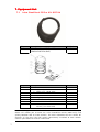
1
plus
Leica SteerDirect ES
Installation Manual
Version Rev 1.1
English
1. Introduction
Purchase
Congratulations on your purchase of the new Leica SteerDirect
ES Plus.
This guide contains important safety directions as well as
instructions for installing the product and operating it. Refer to
the Safety Precautions for further information. Read carefully
through the Installation Guide before you begin operation of
vehicle. The Leica SteerDirect ES Plus is to be used solely in
combination with Leica Geosystems’ guidance systems.
Therefore it’s mandatory to also observe the directions and
instructions contained in the Leica guidance product manual.
To ensure safety when using the system, please also observe the
directions and instructions contained in the User Manual and
Safety Handbook issued by the agricultural vehicle manufacturer.
This guide describes how to install the Leica SteerDirect ES Plus.
Even if you have installed other Leica Geosystems products
before, we recommend you read this guide to ensure correct
installation of this product.
2
Symbols
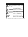
Symbols used in this guide have the following meanings:
Type
Description
Indicates an imminently hazardous
situation which, if not avoided, will result
in death or serious injury.
Indicates a potentially hazardous situation
or an unintended use which, if not
avoided, could result in death or serious
injury.
Indicates a potentially hazardous situation
or an unintended use which, if not
avoided, may result in minor or moderate
injury and / or appreciable material,
financial and environmental damage.
Important paragraphs which must be
adhered to in practice as they enable the
product to be used in a technically correct
and efficient manner.
Note - The absence of specific alerts does not mean that there are no safety
risks involved.
3
3. Contents
1.
Introduction .......................................................................................................... 2
3.
Contents ............................................................................................................... 4
4.
Product Overview .................................................................................................. 5
4.1
Product Compatibility ...................................................................................... 5
5.
Pre-Installation Vehicle Preparation ........................................................................ 6
6.
System Description ................................................................................................ 6
7.
Equipment List....................................................................................................... 7
7.1
8.
Leica SteerDirect ES Plus Kit- 812746 .............................................................. 7
Installation ............................................................................................................ 9
8.1
Leica SteerDirect ES Plus Installation ............................................................... 9
8.1.1
Install the Main Gear on the Steering Wheel.............................................. 9
8.1.2
Examine Steering Wheel and Column ....................................................... 11
8.1.3
Install Spacer (If Needed) ........................................................................ 11
8.1.4
Install the Clamp Ring.............................................................................. 12
8.2
Attach the Anti-rotation Pin........................................................................... 14
8.3
Install the Leica SteerDirect ES Plus MDU ........................................................ 15
9.
Universal Bracket Installation ............................................................................... 17
9.1
Universal Bracket Installation Kit Overview...................................................... 18
9.2
Universal Bracket Installation Procedure ......................................................... 19
10.
Cable Installation .............................................................................................. 21
10.1
SteerDirect-ES Plus Cable ........................................................................... 21
10.2
Engage Switch Mounting ............................................................................ 22
10.3
Power Source ............................................................................................ 22
11.
Power Switch ................................................................................................... 23
12.
Safety Directions .............................................................................................. 24
12.1
General...................................................................................................... 24
12.2
Intended Use ............................................................................................. 24
12.3
Limits of Use ............................................................................................. 25
12.4
Responsibilities .......................................................................................... 25
12.5
Hazards of Use .......................................................................................... 26
13.
4
Care and Maintenance ...................................................................................... 29
4. Product Overview
Benefits
The Leica SteerDirect ES Plus Kit consists of a MDU, associated Wiring
Harness, brackets and bolts which will form the foundation of your new
auto-steer solution.
This Leica SteerDirect Kit is designed to be used in conjunction with the
Leica agricultural guidance products. The installation of a guidance product
is not included in this guide. Please refer to your local dealer or the
relevant guide for further details on these products.
This installation guide will provide the necessary steps to successfully
install the Leica SteerDirect ES Plus Kit.
To understand
this guide
To ease the use of this guide please observe the following advice:
Relating to all pictures and schematics, they are to be seen as reference
only. There may be slight deviations from the actual looks of the Leica
SteerDirect ES Plus. These deviations are caused by individual applications
and have no impact on the function capabilities of the Leica SteerDirect
ES Plus.
Use only original
parts
Leica Geosystems original spare parts are especially designed for the Leica
SteerDirect ES Plus. They live up to the high design standards for safety
and reliability. We advise you, that components or parts not provided by
Leica Geosystems for the Leica SteerDirect ES Plus should not be used
because they might jeopardize the safety and function of the Leica
SteerDirect ES Plus. We therefore cannot be responsible for such redesign
or adaptations. Any obstinate changes on our Leica SteerDirect ES Plus
void the company warranty. In addition conformity declaration or local
authority regulations could be voided. This also applies to the removal of
factory applied seals.
The Leica SteerDirect ES Plus supports you and improves your efficiency,
while working in the field. The responsibility for quality and work related
results rests as always with the driver. As common with all machinery the
basic rule applies. The more exact the system is adjusted, calibrated and
operated the higher the quality of results will be.
4.1
Compatibility
Compatibility
Product Compatibility
The Leica SteerDirect ES Plus Kit is only compatible with the following
Leica Products:• mojo3D/mojoXact combination
• mojo3D/mojoTwist combination
• mojoXact Plus / Universal Terminal combination
• mojoXact Plus / mojo3D combination
Note:
Note : It is not compatible with the mojoRTK console or the mojoMINI.
5
5. PrePre-Installation Vehicle Preparation
1. Park the vehicle on a hard, level surface and block the front and
rear wheels.
2. Remove all dirt and trash from the areas of the vehicle where the
Leica SteerDirect ES Plus will be installed.
Before beginning installation, please ensure that the vehicle is turned off
and a DO NOT START tag is attached to the ignition.
Note: The left and right hand sides of the vehicle are referenced while
standing behind the vehicle, facing the normal direction of travel.
6. System Description
General
The Leica SteerDirect ES Plus is capable of interfacing to existing vehicles
like tractors and other self propelled machines in agriculture and forestry
applications.
The Leica SteerDirect ES Plus kit is composed of the MDU and associated
cabling. The Leica SteerDirect ES Plus Kit is designed to interface to the
Leica guidance system via CAN bus.
The Leica SteerDirect ES Plus is designed to assist the machine operator
to use the equipment more efficiently.
Even when relying on the function of the Leica SteerDirect ES Plus the
driver is still responsible for observation of the machine and the
surrounding area. They should shut down or assume manual steering
control in dangerous situations. To shut down the Leica SteerDirect ES Plus
turn off the power switch so that the lights are off.
6
7. Equipment List
7.1
Leica SteerDirect ES Plus Kit- 812746
Qty
1
Description
Leica SteerDirect ES Plus MDU
(Mechanical Drive Unit)
Article #
812746
Qty
1
Description
Leica SteerDirect ES Switch Kit
Article #
805042
1.
Upper Ring
2.
Spacer 5.75” x 0.50” Thick
3.
Spacer 5.75” x 0.25” Thick
4.
Ring Cap Assembly
5.
Main Gear Assembly
6.
Hardware Kit
7.
Hex Key 7/64” Black Oxide
Hex Key 5/32” Black Oxide
Note:
Note : You may purchase additional Leica SteerDirect ES Plus Switch Kits from your
dealer. This allows you to move the Leica SteerDirect ES Plus MDU easily and
quickly between two or more vehicles. The Leica SteerDirect ES Plus Switch Kit
contains all the parts that will remain permanently attached to each vehicle.
Contact your dealer for further information.
7
Qty
1
Description
Leica SteerDirect ES Plus Anti-Rotation
Pin Kit
Article #
818500
Switch Included with cable
8
Qty
1
Description
Cable, SteerDirect ES Plus
Article #
807606
Qty
1
Description
Cable, SteerDirect ES Plus, Power
Article #
808539
8. Installation
8.1
Leica SteerDirect ES Plus Installation
Refer to Leica SteerDirect ES Plus Switch Kit components on page 7 to identify the parts
used in this section. The tool list below consists of special tools required to complete
the installation. A complete set of common installation tools is assumed.
• 7/64'' Allen Wrench (Supplied)
• 5/32'' Allen Wrench (Supplied)
• 1/4'' Open Wrench
• 1/4'' Nut Driver
• Torque wrench 0 to 20 lbf-in (0 to 2 Nm), for 5/32'' hex bit
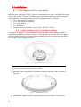
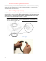
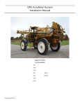
8.1.1 Install the Main Gear on the Steering Wheel
The goal of this section is the installation of the main gear on the steering wheel. A
completed installation is shown in Figure 1. Through the use of switch kits, main gears
can be installed and left on multiple vehicles allowing the user to move the Steer Direct
ES Plus MDU easily between vehicles.
Figure 1 – Completed Main Gear Installation
Note:
Note : The installation of the main gear on the steering wheel does NOT require
removing the steering wheel from the vehicle.
1. Remove 2 hex screws from the Smaller section of the Main Gear as shown in
Figure 2.
Figure 2 – Main Gear Hex Screws
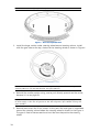
2. Remove the smaller section by pulling downwards as shown in the Figure 3.
9
Note: Tolerances are tight; pull directly downwards on smaller section.
Figure 3 – Main Gear Exploded View
3. Install the larger section under steering wheel around steering column. Install
with the gear side on the top, closest to the steering wheel as shown in Figure 4.
Figure 4 – Installed Main Gear
Note: Weave the gear around the steering wheel spokes if necessary; certain
steering columns may be too thick for the gear opening.
4. Reinstall the smaller section using care to push directly upwards on the sector,
because it is a very tight fit.
Note: To facilitate the fit between the two gear sections, you may apply a drop
of oil or apply a thin film of grease to the two alignment pins before mating the
gear sections.
5. Reinstall and secure the 2 hex screws. At this point the main gear is assembled
around the steering column below the steering wheel as shown in the Figure 4.
The gear is free to move around and must be now clamped to the steering
wheel.
10
8.1.2 Examine Steering Wheel and Column
Examine the steering wheel underside to determine if a spacer is necessary. A steering
wheel with a soft covering material usually requires installation of a spacer to avoid
interference with the MDU housing.
8.1.3 Install Spacer (If Needed)
Install the spacer around the steering column between the steering wheel and the main
gear as shown in Figure 5. Flex the plastic spacer as needed to clear the steering wheel
spokes as shown in Figure 6 The large chamfer on the outside diameter of the spacer
ring should be facing the main gear as shown in Figure 5
Note: Two spacers with different thicknesses are included in the kit. Select the
thinnest spacer that provides sufficient clearance between steering wheel and
the Leica SteerDirect ES Plus MDU.
Figure 5 – Wheel with Spacer
Figure 6 – Spacer Flexing
11
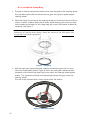
8.1.4 Install the Clamp Ring
1. The gear is free to move around and must be now clamped to the steering wheel.
This procedure will install and center the ring gear for typical 3 spoke shaped
steering wheel.
2. Place the clamp ring on top of the steering wheel and install a minimum of 6 hex
screws. Install a screw on each side of every spoke keeping the screws as close
to the spokes as possible. At this stage keep the screws fairly loose to allow for
centering. See Figure 7.
Note: Two lengths of screws are provided in the kit to support different
thicknesses of steering wheel spokes. Select the shorter of the two screws that
still provides full thread engagement.
Figure 7 – Clamp Ring
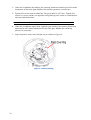
3. With the main gear clamped loosely, rotate and move the gear until 3 screws
touch the three spokes evenly. Figure 8 shows the main gear rotated counterclockwise until three of the mounting screws touch the steering wheel spokes
evenly. This procedure will help to automatically centre the gear under the
steering wheel.
The red circles indicate which circles are touching the spokes
Figure 8 – Main Gear Centred
12
4. Check the installation by rotating the steering wheel and watching for off-center
movement of the main gear. Repeat the centering process as necessary.
5. Tighten the screws with an Allen key. Torque to 6 lbf-in (0.7 Nm). Tighten the
screws in a cross-pattern (as opposed to tightening each screw in a clockwise or
counter-clockwise order).
Note: Do not over-tighten the clamp ring screws.
6. Check the installation again after tightening by rotating the steering wheel and
watching for off-center movement of the main gear. Repeat the centering
process as necessary.
7. Snap the plastic cover over the top ring as shown in Figure 9.
Figure 9 – Plastic Cover Ring
13
8.2
Attach the Anti-rotation Pin
1. Chose the desired MDU orientation. The MDU can be mounted in any orientation
the user chooses. Consider the following when choosing an orientation:
• Ease of installing anti-rotation bracket
• Access to the Power Switch
• Avoid locations where a knee could accidently press the power switch.
• Avoid blocking the vehicle's steering column controls and indicators.
• Cable routing with minimal obstruction in the cab
2. Based on your preferred orientation, choose one of three locations for the Antirotation Pin as shown in Figure 10.
Figure 10 – AntiAnti- rotation Pin Locations
3. Assemble the anti-rotation pin by inserting the long screw through the metal
sleeve provided.
4. Install the anti-rotation pin under the MDU in one of the three positions and
tighten to 100 in.lbs (11.3 Nm) using the 3/16” hex key (Allen key) provided.
Note: The anti-rotation pin must always be kept tight to avoid breakage or
separation. Periodically check the anti-rotation pin and confirm that it is tight.
Always tighten to the specified torque.
14
8.3
Install the Leica SteerDirect ES Plus MDU
This procedure describes the installation and alignment of the Leica SteerDirect ES Plus
MDU to the Main Gear.
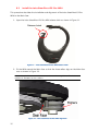
1. Open the Leica SteerDirect ES Plus MDU release latch as shown in Figure 11.
Release Latch
Figure 11 – Leica SteerDirect ES Plus MDU Release Latch
2. Fit the MDU around the Main Gear so that the three rollers align on the Main Gear
race as shown in Figure 12.
Note: The plastic cover on the MDU can be used as a guide to fit the bottom
portion of the MDU to the V-rollers.
Figure 12 – Leica SteerDirect ES Plus MDU Alignment
15
3. Ensure that the main gear Face has properly engaged the three rollers before
closing latch. See Figure 12.
Make sure that the main gear race has properly
engaged the three rollers before closing latch. If the
race is not engaged properly, you risk damaging the
Leica SteerDirect ES Plus and steering wheel while
the Steering System is operating.
4. Rotate the Leica SteerDirect ES Plus MDU manually to ensure smooth rolling.
5. Continue to the Bracket installation section.
16
9. Universal Bracket Installation
This chapter contains the following sections:
• Universal Bracket Installation Kit Overview
• Universal Bracket Installation Procedure
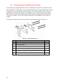
The universal anti-rotation bracket is available through your dealer. It should be used for
vehicles that are not supported with a custom vehicle-specific bracket. Consult your
dealer for a list of all available anti-rotation brackets. An Anti-rotation bracket is
required to complete the Leica SteerDirect ES Plus installation.
805044 - SteerDirect ES Universal Bracket Kit
Note: You may require a different bracket kit depending on your specific vehicle.
If you are installing a vehicle–specific anti-rotation bracket, skip this section of
the manual and refer to the installation instructions provided with your vehiclespecific bracket kit. Vehicle-specific kits currently available are listed below.
Contact your dealer for details.
818503
NEW HOLLAND TVT/TV FORD NEW HOLLAND VERSATILE 9000, BUHLER VERSATILE 2000
818504
JD 47X0/48X0/7930/7630/77X0/78X0/79X0/8XXX/8XXXT/8XXXR/9XXXR/9XXX/9XXXT
818505
CASEIH MX/STX, NH TJ/T9000
818506
JOHN DEERE 9XX0 COMBINES 8, AG CHEM XX54/XX64/XX74, MILLER, RED BALL 7830
818507
JOHN DEERE 6X10/6X20/6X30/7220/7320/7420/7520/7130/7230/7330/7430/7530 STANDARD
818508
CASE MAGNUM 71X0, 72X0, 89X0 MODELS
818509
CASE STEIGERS9XX0, NH 8XX/9XX/1150, CAT 65/75/85 C/D/E
818510
JOHN DEERE 4000-8000 4WD, AGCO ALLIS 9000 SERIES
818511
HAGIE STS ('05 AND NEWER MODELS)
818512
HAGIE STS (2000-2004)
818513
FENDT VARIO AND FAVORIT
818514
CASE 21XX/23XX/25XX/X088
818515
CNH AFX, CAT, BUHLER, NH GENESIS, VERSATILE, AG-CHEM CRENLO CAB '00 AND NEWER
818516
INTERNATIONAL 14XX/16XX
818517
CASE IH MXU/MAXXUM/PUMA, NH T60XX0/T70XX0/T80XX0
818518
CASE SPX/FLX/TITAN, NH TG,T80X0
818519
CASE HYDRO/XX86/3X88/5X88
818520
MASSEY FERGUSON, AGCO ALLIS DT, RT, CHALLENGER 500/600
818521
GLEANER RX0, MASSEY 86XX, CAT MT5XXC/6XXC
818522
GLEANER R55/R65/ R75, CHALLENGER 660/670
818523
CAT LEXION 590R
818524
CHALLENGER 670B, GLEANER R66/R76
818525
CHALLENGER 670B, GLEANER S67/S77, MASSEY 6X95 (2011 AND NEWER)
818526
APACHE SPRAYER AS SERIES 500/710/715/850/1000/1010/1210
818527
CASE MXM, JXU, NEW HOLLAND TL, TM, (TS 1997-2003)
818528
JOHN DEERE D 6230, 6330, 6430, 7130, 7230, 7330, 7430
818529
CASE MX MAXXUM 100/110/120/135/150/170, MCCORMICK MT
17
9.1
Universal Bracket Installation Kit Overview
To complete your Leica SteerDirect ES Plus installation and prevent the rotation of the
Leica SteerDirect ES Plus MDU, an anti-rotation bracket must be mounted to the vehicle
steering column just below the steering wheel. This chapter provides instructions for
installing a universal bracket kit that is available as an accessory through your dealer.
Many other brackets are available to fit specific vehicles models and can be ordered
through your dealer. Contact your dealer for details and availability for your vehicle
model.
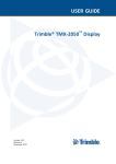
The typical universal bracket kit includes the components shown in Figure 13.
Figure 13 – Universal Bracket Kit
Item Component
Qty
1.
Flange Bearing
1
2.
Fifth Wheel Slider
1
3.
Front Bracket
1
4.
Back Bracket (‘V’ shape)
1
5.
Clamping screws. Machine Screw Phillips 1/4 - 20 x 4" 4
(Washers, Lock Washers and Nuts)
Bolts 5/16 -18 x 3/4" (Slider Attaching Bolts)
2
6.
18
9.2
Universal Bracket Installation Procedure
Note: The Leica SteerDirect ES Plus MDU is attached to the steering wheel prior
to installation of the bracket kit.
1. Make sure that you have all of the required parts. See Figure 13.
2. Attach front bracket to the fifth wheel slider bracket using the two bolts (slider
attaching bolts). See Figure 14. Tighten finger tight.
Note: The slider will require adjustment once installed on the steering column.
Figure 14 – Fifth Wheel Slider Attachment
3. Place the flange bearing assembly over anti-rotation pin. Figure 15
Note: It is important that the anti-rotation pin is placed through the flange
bearing before attaching the Fifth Wheel Bracket.
Figure 15 – Slide Flange Bearing
19
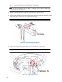
4. Attach the back bracket to the front bracket using the four machine screws
clamping the steering column between the front and back brackets. Figure 16
Figure 16 – Attaching the Brackets
5. Tighten the clamping assembly.
Make sure the assembly does not interfere with any
of the vehicle control levers on the steering column.
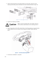
6. Adjust the position of the fifth wheel slider so the flange bearing is approximately
in the middle of the anti-rotation pin and tighten the bolts (Slider attaching
bolts).
Figure 17 – Fifth Wheel Slider Adjustment
7. The bracket installation is complete.
20
10.
Cable Installation
All cabling must be secured away from operator
controls.
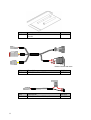
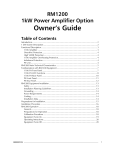
Two cables are used to connect the MDU to the Guidance system. The SteerDirect-ES
Plus cable (807606) and the power cable (808539). Figure 18 shows the overall
connection.
Figure 18 - Cabling Overview
10.1 SteerDirect-ES Plus Cable
1. Connect the round 9-pin connector to the bottom connector of the MDU. Rotate
the coupling of the connector until it locks into place.
2. If using a mojoXact or mojoXact Plus connect the 6-pin connector labelled “CAN
Bus” to the Yellow port of the port expansion cable.
3. If using a mojo3D with a Twist connect the 6-Pin connector labelled “CAN Bus”
to the Twist with the other end of the twist connected to the yellow port of the
port expansion cable.
4. Connect the 2-Pin connector labelled “Power In” to the power cable.
Note: The connector labelled “Wheel Angle Sensor” is not used.
21
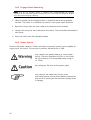
10.2 Engage Switch Mounting
Note: Use of the engage switch is optional but recommended for remote
engaging of the steering system and ease of use. If not used the guidance display
must be used to engage steering.
1. Select a location for the Engage Switch; it should be close to the operator
controls. The switch is a standard size and fits most spare switch locations.
2. Route the crimps from the main cable to the desired switch location.
3. Connect the crimps to the underside of the switch. The connection orientation is
not critical.
4. Press the switch into the selected location.
10.3 Power Source
Connect the power cable to a 12Vdc switched (accessories) power source capable of
supply up to 4A current. The red wire is positive, the black wire is GND.
Only Connect the power cable to a 12Vdc power
source. The Leica SteerDirect ES Plus is not suited
for 24V machines. The Acceptable power range is
11-15Vdc.
Do not bypass the fuse on the power cable.
Only connect the SteerDirect ES Plus to an
accessories power source. Direct battery connection
may result in draining of the machine’s battery when
in storage.
22
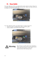
11.
Power Switch
The Leica SteerDirect ES Plus is equipped with a power switch as shown in Figure 19
this allows the operator to disable the steering system. Position the switch with the 0
to disable the Leica SteerDirect ES Plus
Figure 19 - Power Switch
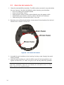
The Leica SteerDirect ES Plus has two LED lights as shown in Figure 20.
• When the system is powered LED1 will stay constant green.
• When the MDU is active LED2 will flash yellow.
Figure 20 - MDU LEDs
When driving on a public road the Leica SteerDirectES Plus must be switch off. Ensure the power light is
turned off and the guidance system can’t
communicate with the steering system.
23
12.
Safety Directions
12.1 General
The Leica SteerDirect ES Plus is to be used solely in combination
with Leica Guidance systems. Therefore it’s mandatory to also
observe the directions and instructions contained in the Leica
guidance product manual.
Description
The following directions should enable the person responsible for
the product, and the person who actually uses the equipment, to
anticipate and avoid operational hazards.
The person responsible for the product must ensure that all users
understand these directions and adhere to them.
12.2 Intended Use
Permitted Use
•
•
Adverse Use
•
•
•
•
•
•
•
•
•
•
•
The Leica SteerDirect ES Plus is exclusively developed for
usage in agriculture or forestry by persons in control.
The Leica SteerDirect ES Plus is only intended to be fitted
to agricultural tractors. It is not permitted to install this
product in any other vehicles.
Use of the product without instruction.
Use outside of the intended limits.
Disabling safety systems.
Removal of hazard notices.
Opening the product using tools, for example screwdriver,
unless this is specifically permitted for certain functions.
Modification or conversion of the product.
Use after misappropriation.
Use of products with obviously recognizable damages or
defects.
Use with accessories from other manufacturers without the
prior explicit approval of Leica Geosystems.
Inadequate safeguards at the work site, for example when
using on the intended site.
The Leica SteerDirect ES Plus is not suitable for applications on
narrow dikes or on steep hillsides, where danger of vehicle roll
over exists.
Adverse use can lead to injury, malfunction and damage. It is the
task of the person responsible for the equipment to inform the
user about hazards and how to counteract them.
The product is not to be operated until the user has been
instructed on how to work with it.
24
Unauthorized modification of agricultural machine by mounting or
installing the product may alter the function and safety of the
machine.
Precautions:
Follow the instructions of the machine manufacturer. If no
appropriate instruction is available, ask machine manufacturer for
instructions before mounting or installing the product.
12.3 Limits of Use
Environment
Suitable for use in an atmosphere appropriate for permanent
human habitation: not suitable for use in aggressive or explosive
environments.
Local safety authorities and safety experts must be contacted
before working in hazardous areas, or in close proximity to
electrical installations or similar situations by the person in charge
of the product.
12.4 Responsibilities
Manufacturer of
the product
Leica Geosystems AG, CH-9435 Heerbrugg, hereinafter referred to
as Leica Geosystems, is responsible for supplying the product,
including the user manual and original accessories, in a completely
safe condition.
Manufacturers of
non Leica
Geosystems
accessories
The manufacturers of non Leica Geosystems accessories for the
product are responsible for developing, implementing and
communicating safety concepts for their products, and are also
responsible for the effectiveness of those safety concepts in
combination with the Leica Geosystems product.
Person in charge of
the product
•
•
•
•
The person in charge of the product has the following
duties:
To understand the safety instructions of the product.
To be familiar with local regulations relating to safety and
accident prevention.
To inform Leica Geosystems immediately if the product and
the application becomes unsafe.
The person responsible for the product must ensure that it is used
in accordance with the instructions. This person is also
accountable for the training and the deployment of personnel who
use the product and for the safety of the equipment in use.
Unauthorized modification of machines by mounting the product
may alter the function and safety of the machine.
25
12.5 Hazards of Use
Only Leica Geosystems authorized service workshops are entitled to
repair these products.
Beware of inadequate steering if machine is defective like after a
crash or other damaging events or alterations to the machine.
Precautions:
Periodically perform control measurements and field adjustments on
the machine as specified in the User Manual.
While steering or navigating the machine accidents may occur due to
a) the operator not paying attention to the surroundings (persons,
ditches, traffic, etc.), or b) malfunctions (…of a system component,
interference, etc).
Precautions:
The operator assures that the machine is operated, guided and
monitored by a qualified user (e.g. driver). The user has to be able to
take emergency measures, for example an emergency stop.
The absence of instruction, or the inadequate imparting of
instruction, can lead to incorrect or adverse use, and can give rise to
accidents with far-reaching human, material, financial and
environmental consequences.
Precautions:
All users must follow the safety directions given by the manufacturer
and the directions of the person responsible for the product.
During dynamic applications, there is a danger of accidents occurring
if the user does not pay attention to the environmental conditions
around, for example obstacles, excavations or traffic.
Precautions:
The person responsible for the product must make all users fully
aware of the existing dangers.
Inadequate securing of the work site can lead to dangerous
situations, for example in traffic, on building sites, and at industrial
installations.
Precautions:
Always ensure that the work site is adequately secured. Adhere to the
regulations governing safety and accident prevention and road traffic.
If the product is improperly disposed of, the following can happen:
If polymer parts are burnt, poisonous gas are produced which may
impair health.
By disposing of the product irresponsibly you may enable
unauthorized persons to use it in contravention of the regulations,
exposing themselves and third parties to the risk of severe injury and
rendering the environment liable to contamination.
Precautions:
The product must not be disposed with household waste. Dispose of
the product appropriately in accordance with the national regulations
in force in your country. Always prevent access to the product by
unauthorized personnel.
26
Product specific treatment and waste management information can
be downloaded from the Leica Geosystems home page at
http://www.leica-geosystems.com/treatment or received from your
Leica Geosystems dealer.
On public roads and drives always disengage the Leica SteerDirect ES
Plus via the power switch. For safety reasons it is better if you keep
one hand on the steering wheel, when using the Leica SteerDirect ES
Plus at speeds over 6 mph (10 km/h). In case of malfunction you are
able to take action immediately.
With exemption of the driver no other person should ride in the
drivers area of the vehicle fitted with a Leica SteerDirect ES Plus.
Additional persons could distract or block visibility of the driver from
operating and observing the Leica SteerDirect ES Plus which could
lead to dangerous situations.
The presence of a rider on a passenger seat is only acceptable for
brief observations or for training purpose. The passenger seat is
never considered a children seat. Only persons especially experienced,
with the operation of the machine, should be considered for
schooling on a machine which is fitted with a Leica SteerDirect ES
Plus.
Pay special attention that no children are near or on the vehicle which
is fitted with a Leica SteerDirect ES Plus, especially when the Leica
SteerDirect ES Plus is active. Children are unpredictable and
supervision is limited when operating the Leica SteerDirect ES Plus.
They might be exposed to additional danger.
Before starting field work make yourself comfortable with the use of
the Leica SteerDirect ES Plus and the vehicle. As soon as the Leica
SteerDirect ES Plus is activated, an adult, responsible person has to be
in charge of supervision and monitoring. In dangerous situations it is
always safer to disengage the Leica SteerDirect ES Plus and drive by
hand, in order to avoid personal injury or material damage.
27
At no time should there be any person within the danger
zone once the Leica SteerDirect ES Plus system is activated.
At any sign of danger the operator should deactivate the
Leica SteerDirect ES Plus system immediately. He has to ask
any person within the danger zone to leave promptly. Only
when there are no more people within the danger zone can
he re-activate the Leica SteerDirect ES Plus system.
For service and control duties only authorized persons can
enter the danger zone, after verbal confirmation with the
operator. Such people have to be clearly informed about
possible dangers before entering the danger zone. All
activities between the operator and these persons should be
discussed beforehand. All service, adjustment and control
duties on this Leica SteerDirect ES Plus system should only
take place if technically possible, on a parked vehicle with
the engine turned off.
People present within the danger zone are exposed to
serious bodily harm or even death. People could be run over
in case of malfunction of the machine. The operator is
obligated to stop the vehicle as soon as people enter the
danger zone.
Prepare for possible
emergencies
•
•
28
Always have a fire extinguisher and First Aid kit at
hand.
Always have actual emergency phone numbers for
Fire department, ambulance and doctor handy.
13.
Care and Maintenance
This chapter describes the required care and maintenance for your Leica SteerDirect ES
Plus system. Should you require repair services, spare parts or warranty, contact your
dealer. Only the factory or an authorized service centre has the correct parts and
training necessary to service your Leica SteerDirect ES Plus system.
•
•
•
•
•
•
•
Keep the anti-rotation pin tight at all times. Check the anti-rotation pin every
250 hours of operation or every six months, whichever occurs first, and tighten
as necessary. Do not operate the Leica SteerDirect ES Plus unit if the antirotation pin is loose.
Keep the anti-rotation bracket well secured to the steering column at all times.
Check the anti-rotation bracket every 250 hours of operation or every six
months, whichever occurs first, and confirm that it is secure and all fasteners are
tight. Tighten as necessary.
Do not expose your Mechanical Drive Unit (MDU) to water or rain. Store the MDU
in a protected location. On open platform tractors, remove it from the vehicle
when not in use.
Check all cables and electrical connectors every six months. Secure any loose
cables using cable ties.
Clean the outside surfaces of your Mechanical Drive Unit and the three guide
rollers using a damp cloth. Do not apply spray cleaners, spray waxes, liquids or
lubricants such as WD-40. The use of any liquid cleaning agent or lubricant may
damage the internal components of your Mechanical Drive Unit and will void the
factory warranty.
Always clean the main gear and main gear race (see Figure 4 and Figure 12)
with a damp cloth to remove dust before installing the MDU to the steering
wheel. This is especially important when moving the MDU between vehicles.
The Mechanical Drive Unit is manufactured with sealed bearings and self
lubricating components and does not require lubrication. Do not apply oil, grease
or spray lubricants.
Note: Any attempt to open the Mechanical Drive Unit (MDU) will void the factory
warranty.
29
Leica Geosystems AG
Heinrich-Wild-Strasse
CH-9435 Heerbrugg
Switzerland
Phone: +41 71 727 31 31
www.leica-geosystems.com
818502 - Rev 1.1 en
Original text
© 2014 Leica Geosystems AC, Heerbrugg, Switzerland
SteerDirect™ is a registered trademark of Leica Geosystems