1
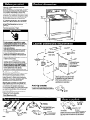
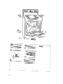
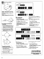
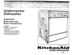
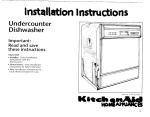
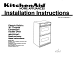
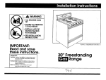
Quick Reference
Table of Contents:
Pages
111
Before you start
El
Product dimensions
111
Cabinet dimensions/requirements
121
Electrical requirements
m-151
Installation steps
IBackeover]
If range does not operate
1-. Back cover1
JBatkcoverl
If YOU need assistance/service
Moving the range
If you need assistance:
Check your Use and Care Guide for a toll-free number to call or call the
dealer from whom you purchased this appliance. The dealer is listed in
the Yellow Pages of your phone directory under “Appliances Household - Major - Service and Repair.”
Call when you:
Q Have questions about range installation or operation.
q Need to obtain the name and number of an authorized
service company.
When you call, you will need:
q The range model number.
m The range serial number.
-+%Q
Both numbers are listed on the model/serial rating plate located on the
oven frame behind the storage drawer panel.
Important: Observe all governing codes
and ordinances.
Proper installation is your responsibility. A qualified
technician must install this range. Make sure you
have everything necessary for correct installation. It
is the installer’s responsibility to comply with
installation clearances specified on the model/serial
rating plate. The model/serial rating plate is located
on the oven frame behind the storage drawer panel.
Check location where range will be installed. The
range should be located for convenient use in
kitchen.
ALL OPENINGS IN THE WALL OR FLOOR WHERE
RANGE IS TO BE INSTALLED MUST BE SEALED.
Cabinet opening dimensions that are shown must
be used. Given dimensions are minimum
clearances.
Grounded electrical outlet is required. See
“Electrical requirements,” Page 2.
27-l/8” depth
with handle
46.718”
overall
height
i
36”
cooktop
height I
Electrical Shock Hazard
It is the customer’s responsibility to contact
a qualified electrical installer and to make sure
that the electrical installation is adequate and in
conformance with National Electrical Code,
ANWNFPA 70 -latest edition*, and all local
codes and ordinances.
Take special care when cutting holes in wall or
iloor. Electrical wires may be behind the wall or
iloor covering and could cause an electrical
shock if you touch them.
Locate any electrical circuits that could be
affected by the installation of this product and
disconnect power circuit.
Failure to follow these instructions could result
30” min. cabinet
opening width
-4
For minimum
clearance to the top
of the cooktop, see
Note.**
K/
n death or serious injury.
Injury Hazard
Toeliminate the risk of burns or fire avoid
nstalling cabinet storage above the cooking
surface. If cabinets are already installed, reduce
:he hazard of reaching over a heated cooking
surface by installing a range hood. The range
load should extend a minimum of 5 inches out
rom the bottom front of the cabinets.
qeaching over a heated cooking surface could
esult in a serious burn or other injury.
5-l/2”
max.
Do Not pinch the power
supply cord between the
range and the wall.
Wall receptacle V to 22” from eftber
cabinet, S-112” max.
from floor. Position
receptacle as shown.
Do Not seal the range to
the side cabinets.
:
IIF
J
Mobile home installation
The installation of this range must conform with the
Manufactured Home Construction and Safety
Standard, Title 24 CFR, Part 3280 [formerly the
Federal Standard for Mobile Home Construction
and Safety, Title 24, HUD (Part 28011or, when such
standard is not applicable, the Standard for
Manufactured Home Installations, ANSI
A225.1/NFPA 501A, or with local codes.
When this range is installed in a mobile home, it
must be secured to the floor during transit. Any
method of securing the range is adequate as long
as it conforms to the standards listed above.
Four-wire power supply cord or cable must be used
in a mobile home installation. The appliance wiring
will need to be revised. See “Four-wire electrical
cOnnectiOn,n Page 3.
r
\
**Note: 24” min. when bottom of wood or metal
cabinet is protected by not less than l/4” flame
retardant millboard coveted with not less than
No. 28 MSG sheet steel, 0.015” stainless steel,
0.024” aluminum or 0.020” copper.
30” min. clearance between the top of the
cooking platform and the bottom of an
unprotected wood or metal cabinet.
Anti-t ip bracket
The floor-mou ted anti-tip bracket MUST be installed.
To install the anti-tip bracket shipped with the range, see
Page 2 and the anti-tip bracket template/instruction
sheet
Copies of the standards listed may be obtained from:
* National Fire Protection
Batterymarch
Park
Quincy, Massachusetts
Association
02269
2 plastic
anchors
bR)6
concrete/ceramic floors:
3/16” carbide-tipped masonry
drill bit (Hammer may be
needed for anchors.)
Page 1
O
screws (MO x 1-l/2”)
floor-mounted
anti-tip bracket
Not shown:
literature pack
3 brass terminal block nuts
Brackets must be securely mounted to sub-floor. Thickness of
flooring may require longer screws to anchor bracket to subfloor. longer screws are available from your local hardware
store.
Range must be connected to the proper electrical
voltage and frequency as specified on the model/serial
rating plate. (The model/serial rating plate is located on
the oven frame behind the storage drawer panel.)
q CONNECT WITH COPPER WIRE ONLY.
j7J A three-wire or four-wire, single-phase, 120/240volt, 60-Hz, AC-only, electrical supply (or three-wire or
four-wire 120/208-volt if specified on the model/serial
rating plate) is required on a separate, 40-ampere
circuit, fused on both sides of the line.
Electrical Shock Hazard
Electrical ground is required on this range.
Do Not ground to a gas pipe.
Do Not change the power supply cord plug. lf it
does not fit the outlet, have a proper outlet
installed by a qualified electrician.
Do Not have a fuse in the neutral or grounding
circuit. A fuse in the neutral or grounding circuit
could result in electrical shock.
Do Not use an extension cord with this appliance.
Check with a qualified electrician if you are not
sure the range is properly grounded.
Failure to follow these instructions could result in
death or serious injury.
If codes permit and a separate grounding wire is
used, it is recommended that a qualified electrician
determine that the grounding path is adequate.
Power supply cord is not supplied, but is available
through your local electrical supply house.
q
A time-delay fuse or circuit breaker is
recommended.
q Local codes may permit the use of a U.L.-listed,
250~volt, 40-ampere range power supply cord (pigtail).
This cord contains three, No.-10 copper wires and
matches a three-wire receptacle of NEMA Type lo-50R,
shown in Figure 1. Connectors on the appliance end
must be provided at the point the power supply cord
enters the appliance.
q The range can be connected directly to the fused
disconnect (or circuit breaker box) through flexible,
armored or non-metallic sheathed, copper cable (with
grounding wire). Allow two to three feet of slack in the
line so that it can be moved if servicing is ever
necessary.
If connecting to a four-wire system:
This range is manufactured with the ground
connected to the cabinet. The ground must be
revised so the green grounding wire of the fourwire power supply cord is connected to the
cabinet. See “Four-wire electrical connection,”
section, Page 3.
When a four-wire receptacle of NEMA Type 1450R is used (see Figure 21, a matching U.L.-listed,
four-wire, 250-volt, 40-ampere, range power
supply cord (pigtail) must be used. This cord
contains four copper conductors with ring
terminals at the appliance end, terminating in a
NEMA Type 14-50P plug on the supply end. The
fourth (grounding) conductor must be identified
by a green or green/yellow cover and the neutral
conductor by a white cover. Cord should be Type
SRD or SRDT with a U.L.-listed strain relief and be
at least four feet long.
The MINIMUM conductor sizes for the copper
four-wire power cord are:
40-ampere circuit
2, No.-8 conductors
1, No.-10 white neutral
1, No.-8 green grounding
A U.L.-listed conduit connector must be provided at
each end of the power supply cable (at the range and at
the junction box).
Wire sizes (COPPER WIRE ONLY) and connections must
conform with the rating of the range (40-amperes).
q
3.wire wall
receptacle (lo-50R)
The wiring diagram is located on the back of the
range or on the inside of the storage drawer in a clear
plastic bag.
Figure 1
4-wire wall
receptacle (14-50R)
Figure 2
front leveling leg
Because of the weight and size of this range,
two or more people are required to move it.
Do Not use handle for lifting.
w these instructions could
1
cardboard
shipping b
2
n Do Not remove the cardboard shipping
base at this time.
Put on safety glasses and gloves.
Remove oven racks and parts package
from inside oven. Remove shipping materials,
tape and protective film from range.
3
n
Remove storage drawer. Use a 31
drive ratchet to lower rear leveling legs onehalf turn. Use channel lock pliers to lower front
leveling legs one-half turn.
n
Anti-tip bracket installation
Electrical Shock
Contact a qualified floor covering installer for the
best procedure for drilling mounting holes
through your type floor covering.
Injury Hazard
Take special care when drilling holes in
To reduce the risk of tipping, the range
the floor or wall. Electrical wires may be
located beneath the floor or behind the
wall.
Locate the electrical circuits that could
be affected by the installation of the
anti-tip bracket and turn off power to
these circuits.
Failure to follow these instructions could
result in death or serious injury.
must be secured by a properly installed
floor-mounted anti-tip bracket, supplied
with the range.
Save these Installation Instructions. If
the range is moved to a new location,
the anti-tip bracket must be removed
and reinstalled in the new location.
Failure to follow these instructions could
result in injury.
4
Use the anti-tip bracket
template/instruction sheet to install the
anti-tip bracket.
Anti-tip bracket must be anchored
securely to the sub-floor.
Depending on the thickness
of your flooring, longer screws
may be necessary to anchor the
bracket to the sub-floor.
Longer screws are
available from your local
hardware store.
n
Check that range is on cardboard shipping base
to protect floor covering.
5
n
position.
Page 2
Move range close to final operating
Electrical connection
Three-wire electrical connection:
silvercolored
terminal
block screw.
rr ,t
IuH\\l,grounding
link
\\’
-I
Electrical Shock Hazard
Electrical ground is required on this range.
Do Not connect to the electrical supply until
the range is permanently grounded.
Disconnect the power to the junction box
before making the electrical connection.
This range must be connected to a grounded,
metallic, permanent wiring system or a
grounding connector should be connected to
the grounding terminal or wire lead on the
range.
Failure to follow these instructions could
result in death or serious injury.
Pull cover down
and remove.
l-l
UL-listed strain relief
and 40-ampere range
power supply cord
I-
I
Figure 3
Use this method ONLY if local codes PERMIT
connecting cabinet-grounding conductor to neutral
wire of power supply cord.
7. Use the brass terminal nuts attached to the
inside of the terminal block cover to connect the
neutral wire (center wire) to the silver-colored
terminal screw on the terminal block.
See Figure 3.
8. Connect the other two wires to outer terminal
screws on the terminal block. See Figure 3.
9. Do Not loosen factory-installed nuts already on
the terminal. Tighten nuts with 3/8’ nut driver
for proper electrical connection.
10. Tighten the strain relief screws.
11. Replace the terminal block cover.
12. Plug power supply cord into grounded electrical
outlet.
This range may be connected directly to the fuse
disconnect or circuit breaker box; or with a U.L.-listed,
40.ampere range power supply cable. Depending on
your electrical supply, make the required three-wire or
four-wire connection.
1. Disconnect the power supply.
2. Remove the knock-out for the
power supply cable.
3. Assemble a U.L.-listed conduit
connector in the power supply
cable opening.
4. Strio outer coverinn back 3 inches
connector.
from end, exposing wires.
Strip the insulation back
1 inch from the end of
each wire.
5. Form the bare wire into a “U”
shaped hook.
6. Insert the power supply cable
through the conduit connector, allowing enough
slack to easily attach the wiring terminal block.
7. Complete electrical connection according to your
type electrical supply (“Three-wire electrical
connection” or “Four-wire electrical connection.“)
Three-wire electrical connection:
silver-colored
/terminal
block
screw
grounding
link
ne 2
line 1
neutral
(white wire)
-~
terminal
block cover
Four-wire electrical connection:
Figure 6
U.L-listed conduit connec tor
and power supply cable.
Use this method ONLY if local codes PERMlT
connecting cabinet-grounding conductor to neutral
wire of power supply cable.
Figure 4
screws
6
Remove the terminal block cover screws
n located on the back of range. Pull cover
down and towards you to remove cover from
range.
Depending on your electrical supply,
7 n make the three-wire or four-wire
connection following the “Power supply cord
method” or “Direct wire method” instructions.
grounding
grounding-link
,screw
silver-colored
terminal
block screw
I
link -
?\
8. Use the brass terminal nuts attached to the inside
of the terminal block cover to connect the neutral
wire (white wire) to the silver-colored terminal
screw on the terminal block. See Figure 6.
9. Connect the other two wires to outer terminal
screws on the terminal block. See Figure 6.
10. Do Not loosen factory-installed nuts already on
the terminal. Tighten nuts with 3/8’ nut driver for
proper electrical connection.
11. Tighten the locking ring and clamping screws of
the conduit connector.
12. Reolace the terminal block cover.
Four-wire electrical connection:
l-amen
wire
(center
groundinglink screw
lin
This range is manufactured with the neutral
terminal connected to the cabinet. Use a threewire, U.L.-listed, 40-ampere power supply cord
(pigtail); or if local codes Do Not permit
grounding through the neutral, use a four-wire
power supply cord rated at 250 volts, 40-amperes
and investigated for use with ranges. (See “Fourwire electrical connection.“)
remove knockout
Gus:::
1. Disconnect the power supply.
2. Remove the knockout for the 40-ampere
power supply cord.
3. Assemble a U.L.-listed strain relief in the
opening.
4. Insert the power supply cord through the
strain relief, allowing enough slack to easily
attach the wiring to the terminal block.
5. Use only ring-type terminals to connect the
power supply. To secure the power supply
cord, use the 3/8’ brass terminal nuts attached
to the inside of the terminal block cover. Be
sure nuts are installed tight.
6. Complete electrical connection according to
your type electrical supply (“Three-wire
electrical connection” or “Four-wire electrical
connection.“)
Page 3
- -
ain relief
re range
power supply cord
Figure 5
Use this method for mobile homes and whenever
four-wire installation is required.
7. Remove the grounding-link screw from the
range frame. Save the grounding-link screw.
Bend up the grounding link so that it does not
contact the range. See Figure 4.
8. Connect the green grounding wire from power
supply cord to the range using the grounding-link
screw. The grounding wire must ba attached first
and must not contact any other terminal.
See Figure 5.
9. Connect the neutral wire (center wire) to the
center, silver-colored terminal screw on the
terminal block using the brass terminal nuts that
are attached to the inside of the terminal block
cover. See Figure 5.
10. Connect the other two wires to the outer
terminals on the terminal block. See Figure 5.
11. Do Not loosen the factory installed nuts already
on the terminal. Tighten nuts with 3/8’ nut driver
for proper electrical connection.
12. Tighten the strain relief screws.
13. Replace the terminal block cover.
14. Plug power supply cord into grounded electrical
outlet.
/
44ver-colored
terminal block
screw
neutral wire
connector and
Use this method for mobile homes and whenever
four-wire installation is required.
8. Remove the grounding-link screw from the range
frame. Save the grounding-link screw. Bend up
the grounding link so that it does not contact the
range. See Figure 7.
9. Connect the bare grounding wire from power
supply cable to the range using the groundinglink screw. The grounding wire must be attached
first and must not contact any other terminal.
See Figure 8.
10. Connect the neutral wire (white wire) to the
center, silver-colored terminal screw on the
terminal block using the brass terminal nuts that
are attached to the inside of the terminal block
cover. See Figure 8.
11. Connect the other two wires to the outer
terminals on the terminal block. See Figure 8.
12. Do NOT loosen the factory installed nuts already
on the terminal. Tighten nuts with 3/8’ nut driver
for proper electrical connection.
13. Tighten the locking ring and clamping screws of
the conduit connector.
14. Replace the terminal block cover.
Check that
Connect
power
supply cord
or power
supply cable
nemove shipping
-..C--Ll
Remove oven
racks and parts
nsl.-LS.“*
I
I__
. ..I
-
.i
Install antitip bracket
Sfcure range
with anti-tip
bracket
Level range
LOosen
leveling
Operating position
iBeforemoving range across floor, check that
range is still on cardboard shipping base to
protect floor covering.
8
IC. .1
11Mailing the range in a mobile
l home, YOUMUST secure the range to
the floor. Any method of securing the range is
adequate as long as it conforms to the standards in
the “Mobile home installation” instructions,
Page 1.
IC I
Mo\le the range into final operating
posltlofl. Remove cardboard shipping
base from under range.
l
Place rack in Oven. Place level on rack, first side
to
side; then front to back.
9
8 Check that rear leveling leg is engaged in
M-tip bracket.
lf range iS not level, pull range forward until rear
leveling kg is removed from the anti-tip bracket
Use 38’ drive ratchet and channel lock pliers to ’
adjust leveling legs up or down until range is level.
Push range back into position. Check that rear
leveling leg is engaged in anti-tip bracket,
Note: Oven must be level for satisfactory baking
conditions,
Page 4
Check operation
FRONT
13
CLOSE
OFF
DOOR
I
Check the operation of the cooktop
elements: Push in and turn each
surface unit control knob to “HI” position. Check
the operation of the cooktop elements and
indicator lights.
14
n
Check the operation of the oven and
broil elements: Follow the instructions
for your type oven controls.
n
If your oven has electronic control pads
(with or without timer):
OVEN ON 0
(nmcfFOMNW~NFL*SHKG,
1. Press the “BAKE” pad.
*The “BAKE” indicator will light
“350” will appear in the display.
The “START ?” indicator will begin to flash after
5 seconds.
l
CLEAN.
The oven is preheated when the “PREHEAT”
indicator light goes off (console A only), you hear
a l-second tone and the countdown changes
to “350”.
* Note: “PREHEAT” indicator light will not be
displayed if oven temperature is over 170°F.
l
OVEN HEATING
0
y&”
BROIL.
l
DOO~~L~CXE&CL~A~~~,
2. Press the START/ENTER pad.
The “PREHEAT” or “HEAT,” and “ON”
indicators will light.
The display will show the automatic countdown
time (6 minutes) needed to preheat the oven for
selected temperature.
The bottom element should glow red.
The upper element should become hot, but not
glow red.
l
l
If your range has oven temperature
control knob:
1. Set the oven temperature control to 350°F.
The bottom element should glow red and the
“OVEN ON” and “OVEN HEATING” indicator
lights should be on.
The upper element should become hot but
not glow red. The “OVEN HEATING” indicator
light goes off when the oven is preheated.
l
l
l
3. Press the “OFF/CANCEL” pad.
4. Press the “CUSTOM BROIL” pad.
“500” will appear in the display.
The “BROIL” indicator will light.
The “START ?” indicator will begin to flash
after 5 seconds,
l
l
l
5. Press the “START/ENTER” pad.
The “ON” and “HEAT” (console B only)
indicators will light.
The upper element should glow red.
l
l
6. Press the “OFF/CANCEL” pad.
l
2. Set the oven temperature control to “BROIL.”
The upper element should glow red and the
“OVEN ON” and “OVEN HEATING”indicator
lights should be on.
l
3. Turn the control knob to the “OFF” position.
OFF
.
BROIL
. BAKE
.
!m* -.--wOFF
.
BROIL
.
e
l 200
450 l
.
/
.
400. ,
_
.
350 ’
300
\
250
If your range has oven selector and
temperature control knobs,
D
If your oven has electronic control pads
and a timer:
1. Press the “BAKE” pad.
The “BAKE” indicator will light
“350°F” will appear in the display.
The “START ?” indicator will begin to flash after
5 seconds (console D only).
l
l
l
2. Press the START/ENTER pad.
“PrE” and “4:15” will appear in the display.
“HEAT” and “ON” and indicators will light.
The bottom element should glow red.
The upper element should become hot but not
glow red.
l
l
1. Set the oven selector control to “BAKE” and
the oven temperature control to 350”.
9The bottom element should glow red and the
indicator light should be on.
The upper element should become hot but
not glow red. The oven indicator light goes
off when the oven is preheated.
l
l
The oven is preheated when the time in the display
counts down to “O:OO,” you hear a l-second tone,
and “PrE” changes to “350°F.”
3. Press the “OFF/CANCEL” pad.
4. Press the “CUSTOM BROIL” pad.
“500°F” will appear in the display.
“BROIL” indicator will light.
The “START ?” indicator will begin to flash after
5 seconds (console D only).
l
l
l
5. Press the “START/ENTER” pad.
“HEAT” and “ON” indicators will light.
The upper element should glow red.
l
l
6. Press the “OFF/CANCEL” pad.
l
2. Set the oven selector to “BROIL” and the oven
temperature control to “BROIL”.
The upper element should glow red and the
indicator light should be on.
l
3. Turn the control knob to the “OFF” position.
Page 5
To get the most efficient use
from your new electric range,
read your Use and Care Guide.
Keep Installation Instructions and
Guide close to the electric range
for easy reference.
If range does not operate:
Moving the range:
q
Check that the circuit breaker is not tripped or
the house fuse blown.
l7J Check that the power supply cord is plugged
into the wall receptacle.
q See Use and Care Guide for troubleshooting
list.
If you need assistance:
If you have questions about operating, cleaning or
maintaining your range:
q Refer to Use and Care Guide.
q Call the Consumer Assistance Center. Check
your Use and Care Guide for a toll-free number
to call or call the dealer from whom you
purchased this appliance. The dealer is listed in
the Yellow Pages of your phone directory under
“Appliances - Household -Major-Service
and Repair.”
If you need service:
Maintain the quality built into your range by calling an
authorized service company.
To obtain the name and number of the authorized
service company:
q Contact the dealer from whom you purchased
your range; or
q Look in the Yellow Pages of your telephone
directory under “Appliances-Household
Major - Service and Repair;” or
I~J Call the Consumer Assistance Center.
The toll-free number is listed in your Use and
Care Guide.
When you call, you will need:
q The range model number.
q The range serial number.
Both numbers are listed on the model/serial rating
plate located on the oven frame behind the storage
drawer panel.
Part No. 3195944 Rev. A
0 1996
Injury Hazard
Because of the weight and size of this range,
two or more people are required to move it.
All ranges can tip.
Do Not step, lean or sit on the range drawer or
door.
The anti-tip device packed with range must be
installed. See Installation Instructions.
Failure to follow these instructions could result
in injury.
Benton Harbor, Michigan 49022
When moving range, slide range onto cardboard or
hardboard to prevent damaging the floor covering.
If removing the range is necessary for cleaning or
maintenance:
1. Disconnect the electrical supply. If necessary,
pull the range out, away from the wall, just far
enough to disconnect the power supply cord.
2. Remove range to complete cleaning or
maintenance.
3. Move range back into operating position.
Remove drawer or look underneath range
(a flashlight may be needed). Check that leg is
engaged in anti-tip bracket. If leg is not properly
engaged, remove and reposition bracket to
insure that leg fits properly in bracket.
4. Check that range is level.
5. Reconnect the electrical supply. Reinstall storage
drawer.
Printed in U.S.A.