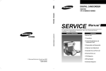
1
VIDEO CASSETTE RECORDER
SV-613X/611X/610X/510X
SV-613F/610F
SV-613B
SV-B150B/B150X/B130G
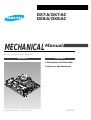
SERVICE
Manual
For mechanical disassembly and adjustment, refer to the “Mechanical Manual”
(DX7-A/AC, DX8-A/AC
AC68-20392A).
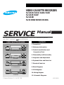
VIDEO CASSETTE RECORDER
CONTENTS
1. Precautions
POWER
EJECT
REW
REC
PLAY
F.F
STOP
2. Reference Information
PROGRAM
SYSTEM
SV-613X/611X/610X/613F/610F/613B
3. Product Specifications and
Comparison Chart
POWER
W
RE
EJECT
REC
PLAY
F.F
STOP
4. Disassembly and Reassembly
PROGRAM
SYSTEM
SV-510X
5. Alignment and Adjustment
6. Exploded View and Parts List
7. Electrical Parts List
SV-B150B/B150X
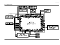
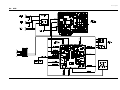
8. Block Diagrams
9. PCB Diagrams
10. Wiring Diagram
SV-B130G
© Samsung Electronics Co., Ltd. APR. 1998
11. Schematic Diagrams
AC68-20402A
1. Precautions
1. Be sure that all of the built-in protective devices are
replaced. Restore any missing protective shields.
2. When reinstalling the chassis and its assemblies, be
sure to restore all pretective devices, including :
control knobs and compartment covers.
3. Make sure that there are no cabinet openings
through which people--particularly children
--might insert fingers and contact dangerous
voltages. Such openings include the spacing
between the picture tube and the cabinet mask,
excessively wide cabinet ventilation slots, and
improperly fitted back covers.
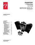
(Reading should
not be above
0.5mA)
Device
Under
Test
Leakage
Currant
Tester
Test all
exposed metal
surfaces
2-Wire Cord
Also test with
plug reversed
(using AC adapter
plug as required)
Earth
Ground
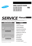
Fig. 1-1 AC Leakage Test
If the measured resistance is less than 1.0 megohm
or greater than 5.2 megohms, an abnormality exists
that must be corrected before the unit is returned
to the customer.
4. Leakage Current Hot Check (See Fig. 1) :
Warning : Do not use an isolation transformer
during this test. Use a leakage current tester or a
metering system that complies with American
National Standards Institute (ANSI C101.1,
Leakage Current for Appliances), and Underwriters
Laboratories (UL Publication UL1410, 59.7).
5. With the unit completely reassembled, plug the AC
line cord directly the power outlet. With the unitÕs
AC switch first in the ON position and then OFF,
measure the current between a known erath
ground (metal water pipe, conduit, etc.) and all
exposed metal parts, including : antennas, handle
brackets, metal cabinets, screwheads and control
shafts. The current measured should not exceed
0.5 milliamp. Reverse the power-plug prongs in the
AC outlet and repeat the test.
6. X-ray Limits :
The picture tube is designed to prohibit X-ray
emissions. To ensure continued X-ray protection,
replace the picture tube only with one that is the
same type as the original.
Samsung Electronics
7. Antenna Cold Check :
With the unitÕs AC plug disconnected from the
AC source, connect an electrical jumper across the
two AC prongs. Connect one lead of the ohmmeter
to an AC prong.
Connect the other lead to the coaxial connector.
8. High Voltage Limit :
High voltage must be measured each time
servicing is done on the B+, horizontal deflection
or high voltage circuits.
Heed the high voltage limits. These include the
X-ray protection Specifications Label, and the
Product Safety and X-ray Warning Note on the
service data schematic.
9. Some semiconductor (Òsolid stateÓ) devices are
easily damaged by static electricity.
Such components are called Electrostatically
Sensitive Devices (ESDs); examples include
integrated circuits and some field-effect transistors.
The following techniques will reduce the
occurrence of component damage caused by static
electricity.
10. Immediately before handling sny semiconductor
components or assemblies, drain the electrostatic
charge from your body by touching a known
earth ground. Alternatively, wear a discharging
Wrist-strap device. (Be sure to remove it prior to
applying power--this is an electric shock
precaution.)
1-1
Precautions
11. High voltage is maintained within specified limits
by close-tolerance, safety-related components and
adjustments. If the high voltage exceeds the
specified limits, check each of the special
components.
12. Design Alteration Warning :
Never alter or add to the mechanical or electrical
design of this unit. Example : Do not add
auxiliary audio or video connectors. Such
alterations might create a safety hazard. Also, any
design changes or additions will void the
manufacturerÕs warranty.
13. Hot Chassis Warning :
Some TV receiver chassis are electrically
connected directly to one conductor of the AC
power cord. If an isolation transformer is not
used, these units may be safely serviced only if
the AC power plug is inserted so that the chassis
is connected to the ground side of the AC source.
To confirm that the AC power plug is inserted
correctly, do the following : Using an AC
voltmeter, measure the voltage between the
chassis and a known earth ground. If the reading
is greater than 1.0V, remove the AC power plug,
reverse its polarity and reinsert. Re-measure the
voltage between the chassis and ground.
14. Some TV chassis are designed to operate with 85
volts AC between chassis and ground, regardless
of the AC plug polarity. These units can be safely
serviced only if an isolation transformer inserted
between the receiver and the power source.
18. Picture Tube Implosion Warning :
The picture tube in this receiver employs
Òintegral implosionÓ protection. To ensure
continued implosion protection, make sure that
the replacement picture tube is the same as the
original.
19. Do not remove, install or handle the picture tube
without first putting on shatterproof goggles
equipped with side shields. Never handle the
picture tube by its neck. Some Òin-lineÓ picture
tubes are equipped with a permanently attached
deflection yoke; do not try to remove such
Òpermanently attachedÓ yokes from the picture
tube.
20. Product Safety Notice :
Some electrical and mechanical parts have special
safety-related characteristics which might not be
obvious from visual inspection. These safety
features and the protection they give might be
lost if the replacement component differs from the
original--even if the replacement is rated for
higher voltage, wattage, etc.
Components that are critical for safety are
indicated in the circuit diagram by shading,
(
or
).
Use replacement components that have the same
ratings, especially for flame resistance and
dielectric strength specifications. A replacement
part that does not have the same safety
characteristics as the original might create shock,
fire or other hazards.
15. Never defeat any of the B+ voltage interlocks.
Do not apply AC power to the unit (or any of its
assemblies) unless all solid-state heat sinks are
correctly installed.
16. Always connect a test instrumentÕs ground lead to
the instrument chassis ground before connecting
the positive lead; always remove the instrumentÕs
ground lead last.
17. Observe the original lead dress, especially near
the following areas : Antenna wiring, sharp
edges, and especially the AC and high voltage
power supplies. Always inspect for pinched, outof-place, or frayed wiring. Do not change the
spacing between components and the printed
circuit board. Check the AC power cord for
damage. Make sure that leads and components
do not touch thermally hot parts.
1-2
Samsung Electronics
2. Reference Information
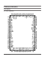
2-1 IC BLOCK
2-1-1 IC601 (HD6473977)
Samsung Electronics
2-1
Reference Information
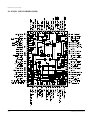
2-1-2 IC301 (SS11511M/SS11501M)
2-2
Samsung Electronics
Reference Information
2-1-3 IC302 (LA7416)
Samsung Electronics
2-3
Reference Information
2-1-4 IC303 (SS23377M/SS23378M)
2-4
Samsung Electronics
Reference Information
2-1-5 IC501 (LA72633)
Samsung Electronics
2-5
Reference Information
2-1-6 IC801 (KA8119)
2-6
Samsung Electronics
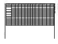
3. Product Specifications and Comparison Chart
3-1 Product Specifications
Design and specifications are subject to change without notice.
Operation
Description
Format
VHS PAL standard (except middle east asia : VHS PAL/NTSC standard)
Heads
Video : 4 rotary heads
Hi-Fi : 2 rotary heads
Audio/Control : 1 stationary head
Erase : 1 full track erase head
Receiving channel
VHF-I, VHF-III, UHF, Hyperband
Television system
Standard
Standard
Standard
Standard
Standard
B/G (for German & West Europe)
B/G, L’L (for France)
B/G, D/K (for East Europe & Middle East Asia)
I (for U.K)
B/B (for Australia)
Recording system
Luminance
FM azimuth recording
Colour
PAL (NTSC/MESECAM) : Down converted subcarrier phase shifted direct recording
SECAM : 1/4 counted down subcarrier direct recording
NTSC PB on PAL TV
Tape speed
SP : 23.39 mm/sec,
LP : 11.69 mm/sec
Recording/playback time
SP : 3 hours (E-180 Tape),
LP : 6 hours (E-180 Tape)
F.F/REW time
About 100 ~ 190 sec in REW/F.F with E-180 tape
VIDEO
Input
Output
Signal-to-noise ratio
Horizontal resolution
0.5 to 2.0 Vp-p : 75 ohm unbalanced
1.0 ± 0.2 Vp-p : 75 ohm unbalanced
Better than 43 dB (SP)
More than 240 lines (SP)
Audio
Input
Output
Wow and flutter (WTD)
Signal-to-noise ratio
Frequency response
-8 dBm, 47 Kohm unbalanced
-8 ± 3 dBm, 1 Kohm unbalanced
0.4% max (SP)
Hi-Fi : 68dB min (IHF A filter), Mono : 42 dB min (IHF filter)
Hi-Fi : 20Hz ~ 20KHz,
Mono : 100Hz ~ 8KHz
Power requirement
230V or 100 ~ 240V (AC 50/60 Hz)
Power consumption
Approx. 21 watts
Operation temperature
41°F ~ 104°F (5°C ~ 40°C)
Operation humidity
10%-75%
Weight
4.4 Kg (net)
Dimensions (W x H x D)
360 x 92 x 314 mm
Samsung Electronics
3-1
ATS
CANAL+
P/MIERE
VCR/TV
DIAMOND HEAD
(DLC)
X
O
X
O
X
O
O
X
O
X
O
X
O
X
O
O
X
O
X
O
X
O
X
O
O
X
O
O
X
X
O
O
O
X
O
X
O
O
O
X
X
O
O
O
X
O
X
SV-610F
O
O
X
X
X
O
O
O
X
O
X
SV-613B
X
O
X
O
X
X
X
X
X
X
X
O
O
X
X
X
O
O
O
X
O
X
X
X
O
X
X
O
O
O
X
O
X
O
X
X
X
X
O
O
O
X
O
X
X
O
X
X
O
O
O
X
O
X
A2
NICAM
S/VIEW V/PLUS
GERMANY
SV-613X
O
X
O
AUSTRIA
SV-613X
O
X
SWITZERLAND
SV-613X
O
X
SV-613F
O
FRANCE
SV-613F
U.K
SPAIN
SV-611X
SV-510X
ITALY
SV-611X
SV-510X
X
PORTUGAL
SV-611X
O
O
X
X
X
O
O
O
X
O
X
FINLAND/SWEDEN/NORWAY
SV-610X
O
O
X
X
X
O
O
X
X
X
X
NETHERLANDS
SV-610X
O
X
X
X
X
O
O
X
X
X
X
BELGIUM
SV-610X
O
O
X
X
X
O
O
X
X
X
X
DENMARK
SV-610X
O
O
X
X
X
O
O
X
X
X
X
SAUDI ARABIA
SV-B130G
X
X
X
X
X
X
X
X
X
X
O
LEBANON
SV-B130G
X
X
X
X
X
X
X
X
X
X
O
AUSTRALIA
SV-B150B
O
X
G-CODE
X
X
X
X
X
X
X
O
NEW ZEALAND
SV-B150X
O
O
G-CODE
X
X
X
X
X
X
X
O
REMARK
Hi-Fi Playback
Hi-Fi Playback
Product Specifications
PDC
MODEL
3-2 Comparison Chart
3-2
VPS
COUNTRY
Samsung Electronics
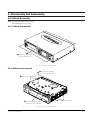
4. Disassembly and Reassembly
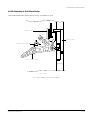
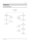
4-1 Cabinet Assembly
Note : Disassemble in the order shown.
Reassemble in reverse order.
4-1-1 Cabinet Top removal
ΠREMOVE 3 SCREWS
(BH;3-4X16-BLACK)
Fig. 4-1 Cabinet Top removal
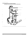
4-1-2 Bottom cover removal
ΠREMOVE 2 SCREWS
(BH;2-3X10-YELLOW)
´ RELEASE 2 SNAPFITS
ˇ Lift up the bottom cover
in the direction of arrow.
´ RELEASE 2 SNAPFITS
Fig. 4-2 Bottom Cover removal
Samsung Electronics
4-1
Disassembly and Reassembly
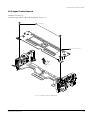
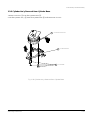
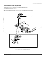
4-1-3 Ass’y Front Panel removal
´ RELEASE 4 HOOKS
ΠREMOVE
KNOB-SHUTTLE
(Top view)
ˇ RELEASE 3 HOOKS
(Bottom view)
Fig. 4-3 Ass’y Front Panel removal
4-2
Samsung Electronics
Disassembly and Reassembly
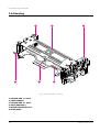
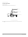
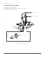
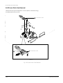
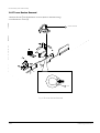
4-1-4 Ass’y Function-Timer removal
Note : Take extreme care not to damage the PCB when removing it.
ΠRELEASE 6 TABS
´ REMOVE 1 SCREW
(BH;2-3X10-YELLOW)
ˇ RELEASE 1 TAB
Fig. 4-4 Ass’y Function-Timer removal
Samsung Electronics
4-3
Disassembly and Reassembly
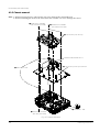
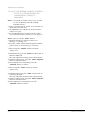
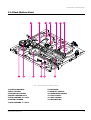
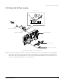
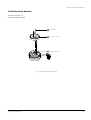
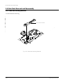
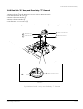
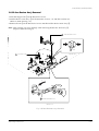
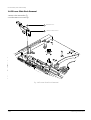
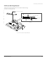
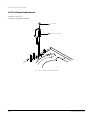
4-1-5 Chassis removal
Note : 1. When removing chassis, take extreme care not to damage the main PCB front.
2. When reinstalling the deck on the main PCB, take extreme care not to damage the sensor.
ΠREMOVE 2 SCREWS
(BH;2-3X12-YELLOW)
´ REMOVE 2 SCREWS
(BH;2-4X12-YELLOW)
¨ Lift the ass'y full deck up.
CONNECTOR BOARD-ASS'Y
∏ Lift the ass'y main up to remove.
ˆ RELEASE 1 TAB
Ø RELEASE 1 TAB
ˇ REMOVE 1 SCREW
(BH;3X12-YELLOW)
Fig. 4-5 Chassis Removal
4-4
Samsung Electronics
Disassembly and Reassembly
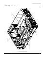
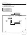
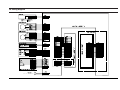
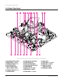
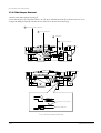
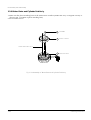
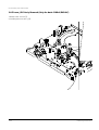
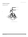
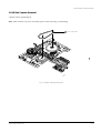
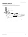
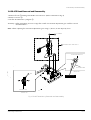
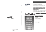
FUNCTION-TIMER BOARD
SUB BOARD
(A2/NICAM)
SHUTTLE BOARD
MAIN BOARD
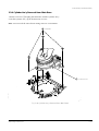
4-2 Circuit Board Locations
Fig. 4-6 Circuit Board Locations
Samsung Electronics
4-5
Disassembly and Reassembly
MEMO
4-6
Samsung Electronics
5. Alignment and Adjustment
Note : After replacing the assÕy full deck, the assÕy main, the cylinder assÕy and the micom(IC601), the remote
control assÕy can be used to adjust the ÒX-point (tracking center) adjustmentÓ and ÒHead S/W pointÓ
adjustment.
5-1 Reference
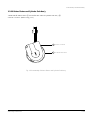
5-1-1 The type of remote control ass’y
EJECT
POWER
POWER BUTTON
1. Remote control assÕy (AC93-10039Y/69099-633-252)
is specified as a service jig in the service manual of
X-5/X-6(DX5-R/DX5-RC/DX6-R/DX6-RC) chassis.
(See Fig. 5-1)
2. Normal remote control assÕy for X-7/X-8
(DX7-R/DX7-RC/DX8-R/DX8-RC) chassis.
(See Fig. 5-2)
TRACKING
CENTER ADJ.
("INPUT" OR "TEST"
AND "1" BUTTON)
1
2
3
4
5
6
Q-PRO
DAILY
7
WEEKLY
8
DISPLAY
CLR/RST
0
PRESET
BAND
SEARCH
MEMORY
FINE
CH
SHIFT SHUTTLE
PLAY
STOP
P/S
REC
INDEX
SLOW
SP LP
A.DUB
SP/LP BUTTON
INPUT
VPS
OUTPUT
633-252
1. The color of some buttons related to TV function are
gold.
2. Audio button is added instead of the test button
hidden behind of inlay.
3. The positions of some buttons are different.
NORMAL REMOTE CONTROL ASS'Y
(CAN ADJUST)
INPUT BUTTON
TEST BUTTON IS
HIDDEN BEHIND
OF INLAY.
REMOTE CONTROL
ASS'Y PART NO.
Fig. 5-1 Remote Control Ass’y Jig for X-5/X-6 Chassis
(AC93-10039Y/69099-633-252)
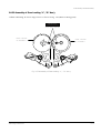
MULTI REMOTE CONTROL ASS'Y
(CAN NOT ADJUST)
TV
POWER
VCR
POWER
EJECT
POWER
TRK
(TRACKING, FINE)
BUTTON
PLAY BUTTON
F.F
REW
5-1-2 How to identify between normal
remote control ass’y and multi
remote control ass’y for X-7/X-8
chassis (See Fig. 5-2)
MENU
9
CLK/COUNT
HEAD S/W ADJ.
("INPUT" OR "TEST"
AND "3" BUTTON)
GOLD COLOR
POWER BUTTON
TRACKING
CENTER ADJ.
("INPUT" OR "TEST"
AND "1" BUTTON)
SPEED BUTTON
SYSTEM
1
2
3
4
5
6
AUDIO
DISPLAY
7
8
9
CLR/RST
CLK/COUNT
INPUT
0
SPEED
AFT
INDEX
A.TRK
HEAD S/W ADJ.
("INPUT" OR "TEST"
AND "3" BUTTON)
VCR
1
2
3
4
5
6
TV
7
8
9
CLR/RST
CLK/COUNT
INPUT BUTTON
FINE
PROG
PLAY
TRK
(TRACKING, FINE)
BUTTON
PLAY BUTTON
INDEX
SOFTEN
OK
GOLD COLOR
F.F
STOP
P/S
REC
MENU
Q-PRO
SLOW
PROG
PLAY
REW
P/S
MENU
VOLUME
FINE
STOP
REC
GOLD COLOR
-/--
SHUTTLE
F.F
REW
INPUT
0
SPEED
SHUTTLE
GOLD COLOR
DISP./
SHARPEN TV/VCR
Q-PRO
SOFTEN
OK
SHARPEN TV/VCR
SLOW
A.DUB
PICTURE
PICTURE
TEST BUTTON IS
HIDDEN BEHIND
OF INLAY.
A.DUB
AUDIO
ADD BUTTON(AUDIO)
Fig. 5-2 Remote Control Ass’y for X-7/X-8 Chassis
Samsung Electronics
5-1
Alignment and Adjustment
5-2 Mechanical Adjustment
Note : Refer to the Mechanical Manual ÒDX7-A/DX7-AC/DX8-A/DX8-AC (AC68-20392A)Ó for the adjustment
and confirmation of assÕy full deck.
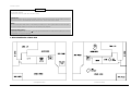
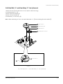
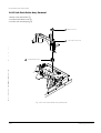
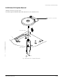
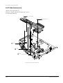
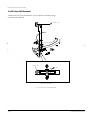
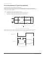
5-2-1 The number and position of test point
Test point : TP02 (CTL Pulse)
TP03 (H’D S/W -Trigger)
TP04 (V. Envelope)
TP05 (Audio out)
AUDIO OUT
V.ENV
CTL
GND
TP04
TP03
TP02
TP01
H'D SW
V.OUT
A.OUT
TP06
TP05
SCART CTL
AGC
TP08
TP07
H’D S/W -TRIGGER
CTL PULSE
V. ENVELOPE
Fig. 5-3 The position of test point (Main PCB-Component side)
5-2
Samsung Electronics
Alignment and Adjustment
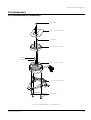
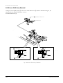
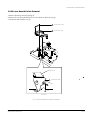
5-2-2 X-Point(Tracking center) adjustment
(See the 2-2-1 (d) AC HEAD
POSITION(X-POINT) ADJUSTMENT
on page 2-3 of the mechanical
manual)
SCREW(B)
AZIMUTH ADJUST
X-POSITION
ADJUST GEAR
5-2-2 (a) IF THE REMOTE CONTROL ASS’Y IS
NOT AVAILABLE
1. Playback the colorbar alignment tape.
2. Connect CH-1 scope probe to ÒTP02Ó and CH-2
scope probe to ÒTP03Ó. And then, trigger head
switching pulse.
3. Set tracking preset to 11msec (2head : 2.7msec,
4, 6head : 11msec) using the ÒFINE (ADJUST)
button
/
of the other remote control
assÕy except the remote control assÕy jig for X-5/
X-6 chassis and the normal remote control assÕy for
X-7/X-8 chassis.
4. Insert the adjusting driver (+) into X-position
adjusting gear. Adjust the driver in either direction
for maximum envelope waveform.
Note : Since the adjusting gear unit may be damaged, do
not adjust by force when adjusting the X-point using the
adjusting driver (+). After turn the X-point adjusting screw
(D) counterclockwise a little, perform the adjustment.
After adjustment is completed, tighten the screw.
<Setting of scope>
- Volt/div. : CH-1 = 0.1V
CH-2 = 0.2V
- Time/div. : 5msec
CH-2 Probe
TP02
H'D S/W Pulse
SCREW(C)
TILT ADJUST
HOLE
SCREW(A)
HEIGHT ADJUST
SCREW(D)
X-POINT LOCKING
Fig. 5-6 Location of A/C Head adjustment screw
5-2-2 (b) IF THE REMOTE CONTROL ASS’Y
(AC93-10039Y/69099-633-252) IS
AVAILABLE
Note : How to use the ÒTESTÓ button.
1. Disattach the inlay of remote control assÕy.
(See Fig. 5-1 and Fig. 5-2)
2. Press the ÒTESTÓ button with the pincers and the
precise driver as shown in Fig. 5-1 and 5-2)
1. When using the ÒINPUTÓ button of remote
control assÕy;
1) Simultaneously press the ÒINPUTÓ button and Ò1Ó
button in PB mode.
This will adjust the tracking center automatically.
2) Set the tracking preset using the ÒFINE (ADJUST)
button of remote control.
3) After adjustment is completed, press the
ÒPOWERÓ button to release.
2. When using the ÒTESTÓ button of remote
control assÕy ;
CH-1 Probe
TP03
CTL Pulse
2.7msec (2 Head), 11msec (4, 6 Head)
Fig. 5-4 Tracking preset adjustment
REMOTE
BUTTONS
CONTROL PULSE REMOVE
PUSH
1) Simultaneously press the ÒTESTÓ button and Ò5Ó
button in PB mode.
This will adjust the tracking center automatically.
2) Set the tracking preset using the ÒFINE (ADJUST)
button of remote control.
3) After adjustment is completed, press the
ÒPOWERÓ button to release.
FINE
FINE
PUSH
Fig. 5-5 Tracking preset adjustment
Samsung Electronics
5-3
Alignment and Adjustment
5-2-2 (b) IF THE NORMAL REMOTE CONTROL
ASS’Y OF X-7/X-8(DX7-R/DX7-RC/
DX8-R/DX8-RC) CHASSIS IS
AVAILABLE
Note 1 : Two kinds of remote control assÕy are used
for X-7/X-8(DX7-R/DX7-RC/DX8-R/
DX8-RC) chassis.
1. One is a normal remote control assÕy, the other is a
multi remote control assÕy
2. All adjustments are adjusted by normal remote
control assÕy only.
3. For the identification of normal remote control
assÕy and multi remote control assÕy, See page 5-1.
Note 2 : How to use the ÒTESTÓ button.
1. Disattach the inlay of remote control assÕy.
(See Fig. 5-1 and Fig. 5-2)
2. Press the ÒTESTÓ button with the pincers and the
precise driver as shown in Fig. 5-1 and 5-2)
1. When using the ÒINPUTÓ button of remote
control assÕy;
1) Simultaneously press the ÒINPUTÓ button and Ò1Ó
button in PB mode.
This will adjust the tracking center automatically.
2) Set the tracking preset using the ÒFINE (ADJUST)
button of remote control.
3) After adjustment is completed, press the
ÒPOWERÓ button to release.
2. When using the ÒTESTÓ button of remote
control assÕy ;
1) Simultaneously press the ÒTESTÓ button and Ò5Ó
button in PB mode.
This will adjust the tracking center automatically.
2) Set the tracking preset using the ÒFINE (ADJUST)
button of remote control.
3) After adjustment is completed, press the
ÒPOWERÓ button to release.
5-4
Samsung Electronics
Alignment and Adjustment
5-3 Electrical Adjustment
5-3-1 Head S/W Adjustment
Note : Only remote control assÕy can adjust.
5-3-1 (a) IF REMOTE CONTROL ASS’Y
(AC93-10039Y/69099-633-252) IS
AVAILABLE
1. When using the ÒINPUTÓ button of remote control
assÕy ;
1) Insert an SP tape into the housing assÕy.
2) Press the ÒPLAYÓ button.
3) Press the ÒINPUTÓ button and Ò3Ó button simultaneously.
4) This will adjust the head S/W point adjustment
automatically.
5) After the adjustment is completed, press
ÒPOWERÓ button to release.
5-3-1 (b) IF NORMAL REMOTE CONTROL
ASS’Y FOR X-7/X-8(DX7-R/DX7-RC/
DX8-R/DX8-RC) CHASSIS IS
AVAILABLE
1. When using the ÒINPUTÓ button of remote control
assÕy ;
1) Insert an SP tape into the housing assÕy.
2) Press the ÒPLAYÓ button.
3) Press the ÒINPUTÓ button and Ò3Ó button
simultaneously.
4) This will adjust the head S/W point adjustment
automatically.
5) After the adjustment is completed, press
ÒPOWERÓ button to release.
2. When using the ÒTESTÓ button of remote control
assÕy ;
1) Insert an SP tape into the housing assÕy.
2) Press the ÒPLAYÓ button.
3) Press the ÒTESTÓ button and ÒSP/LPÓ button
simultaneously.
4) This will adjust the head S/W point adjustment
automatically.
5) After adjustment is completed, press the
ÒPOWERÓ button to release.
Samsung Electronics
2. When using the ÒTESTÓ button of remote control
assÕy ;
1) Insert an SP tape into the housing assÕy.
2) Press the ÒPLAYÓ button.
3) Press the ÒTESTÓ button and ÒSPEEDÓ button
simultaneously.
4) This will adjust the head S/W point adjustment
automatically.
5) After adjustment is completed, press the
ÒPOWERÓ button to release.
5-5
Alignment and Adjustment
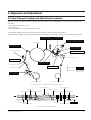
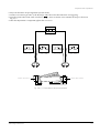
5-3-2 RF AGC Adjustment
(SV-613F/610F Only)
Composition for RF AGC Adjustment
1. ÒE-EÓ, (stop mode), RF signal.
2. TP4N01 and VR4L01,
-. Apply PAL color bar signal to the video input terminal
of the TV channel generator and set channel selector
to CH2 (48.25 MHz).
-. Adjust the point signal level so that the output of
attenuator is 70dBu.
-. Apply the output of attenuator to the ANT IN terminal
of VCR.
-. Set the chaneel of VCR to CH2.
-. Conec DC voltmeter to TP4N01.
-. Adjust VR4L01 for DC3.5 ± 0.1V.
PAL COLOR
BAR SIGNAL
OUT
PAL PATTERN
GENERATOR
TV CH GENERATOR
CH2 (48.25MHz)
VCR
AGC
ATTENUATOR
ANT IN
DC VOLTMETER
TP4N01
AGC T/P
TP4N01
VR4L01
IC4L01
IC4N01
Fig. 5-7 SUB (A2/NICAM) PCB
5-6
Samsung Electronics
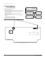
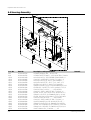
6. Exploded View and Parts List
Page
6-1
Cabinet Assembly - - - - - - - - - - - - - - - - - - - - - - - - - - -
6-2
Mechanical Parts (Top Side) - - - - - - - - - - - - - - - - - - - - 6-4
6-3
Mechanical Parts (Bottom Side) - - - - - - - - - - - - - - - - - 6-6
6-4
Housing Assembly - - - - - - - - - - - - - - - - - - - - - - - - - - - 6-8
Samsung Electronics
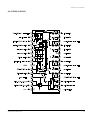
6-2
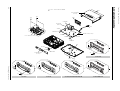
6-1
155
TOP CABINET
(S.N.A)
153
157
108
CN604A
SUB PCB
(S.N.A)
661
SP601
SC301
LD601A
CN605A
MAIN PCB (S.N.A)
PT601A
PT602A
FULL DECK (S.N.A)
SP602
CN601A
22
31
109
21
(S.N.A)
1
157
CN77A
F-TIMER PCB
(S.N.A)
51
SV-B130G
157
22
22
22
22
31
31
31
Samsung Electronics
21
21
1
1
21
21
1
1
51
SV-510X
SV-611X
SV-613X/610X/613F/610F/613B
SV-B150B/B150X
Exploded View and Parts List
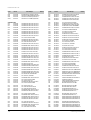
6-1 Cabinet Assembly
6-2
S.N.A : Service Not Available
Exploded View and Parts List
Loc. No
Part No
Description and Specification
Remark
1
21
22
31
51
108
109
153
155
157
661
CN601A
CN604A
CN605A
CN77A
LD601A
PT601A
PT602A
SP601
SP602
SC301
Refer to table below
Refer to table below
AC61-62003A
Refer to table below
Refer to table below
Refer to table below
AC63-32127A
AC60-12126A
AC60-12134A
AC60-10063A
Refer to table below
3809-001090
3809-001048
3809-001049
3809-001094
AC61-22345A
AC61-22344A
AC61-22344A
AC61-22321A
AC61-22321A
AC98-12023J
ASSY-PANEL FRONT
DOOR-CASSETTE
SPRING;-,SUS304,(GE/RCA),-,-,-,DOOR-FRONT
KNOB-SHUTTLE;ABS94,HB
CONNECTOR BOARD-ASSY
COVER-BOTTOM;SV-B80F,SECC,353.2X275,T0.5
SCREW-BH;-,BH,-,4*12,FE,FZY,-,-,SCREW-TAP BH;-,BH,-,2-4X16,-,FE
SCREW-TAPTITE;BH,+,-,M3,L12,ZPC3,SWRCH18
POWER-CORD
CABLE-FLAT;30V,80C,100mm,22P,1.0MM, UL2896
CABLE-FLAT;30V,80C,110mm,6P,1.25MM, UL2896
CABLE-FLAT;30V,80C,100MM,5P,1.25MM, UL2896
CABLE-FLAT;30V,80C,40mm,5P,1.25MM, UL2896
HOLDER-LED;POM,-,-,-,-,HOLDER-PHOTO;POM,-,-,-,-,HOLDER-PHOTO;POM,-,-,-,-,HOLDER-TR;POM,-,-,-,-,HOLDER-TR;POM,-,-,-,-,ASSY-SH/CASE TOP;SV-A140F,IS-PAL
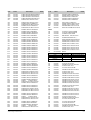
COUNTRY
MODELS
1
21
31
51
108
661
GERMANY
SV-613X
AC98-11244Y
AC64-50958D
X
X
AC61-11039G
AC39-10019A
AUSTRIA
SV-613X
AC98-11244Y
AC64-50958D
X
X
AC61-11039G
AC39-10019A
SWITZERLAND
SV-613X
AC98-11244Y
AC64-50958D
X
X
AC61-11039G
AC39-10019A
SV-613F
AC98-11245R
AC64-50958D
X
X
AC61-11039F
AC39-10019A
SV-613F
AC98-11245R
AC64-50958G
X
X
AC61-11039F
AC39-10019A
SV-610F
AC98-11245E
AC64-50958A
X
X
AC61-11039F
AC39-10019A
U.K
SV-613B
AC98-11246Z
AC64-50958D
X
X
AC61-11039H
AC39-12022K
SPAIN
SV-611X
AC98-11246U
AC64-50958D
AC64-50959J
X
AC61-11039G
AC39-10019A
SV-510X
AC98-11246Y
AC64-50958D
AC64-50959L
AC64-11038A
AC61-11039G
AC39-10019A
SV-611X
AC98-11244V
AC64-50958D
AC64-50959K
X
AC61-11039G
AC39-10019A
SV-510X
AC98-11246Y
AC64-50958D
AC64-50959L
AC64-11038A
AC61-11039G
AC39-10019A
PORTUGAL
SV-611X
AC98-11246U
AC64-50958D
AC64-50959J
X
AC61-11039G
AC39-10019A
FINLAND/SWEDEN/NORWAY
SV-610X
AC98-11245U
AC64-50958D
X
X
AC61-11039J
AC39-10019A
NETHERLANDS
SV-610X
AC98-11245F
AC64-50958D
X
X
AC61-11039J
AC39-10019A
BELGIUM
SV-610X
AC98-11245U
AC64-50958D
X
X
AC61-11039J
AC39-10019A
DENMARK
SV-610X
AC98-11245U
AC64-50958D
X
X
AC61-11039J
AC39-10019A
SAUDI ARABIA
SV-B130G
AC98-11250H
AC64-50934P
AC64-50933C
AC64-10973A
AC61-11039K
AC39-10019A
FRANCE
ITALY
LEBANON
SV-B130G
AC98-11250H
AC64-50934P
AC64-50933C
AC64-10973A
AC61-11039K
AC39-10019A
AUSTRALIA
SV-B150B
AC98-11250K
AC64-50934Q
AC64-50933D
X
AC61-11039K
AC39-10015A
NEW ZEALAND
SV-B150X
AC98-11250L
AC64-50934R
AC64-50933D
X
AC61-11039K
AC39-10015A
Samsung Electronics
6-3
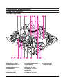
T221
T300
T224
T233
T216
T204
<DX7-AC/DX8-AC
ONLY>
T230
T222
T228
T229
T218
T201
952
T207
T231
901
T203
901
957
T209
T212
920
901
T234
<DX7-AC/DX8-AC ONLY>
T219
T240
T233
900
T217
T239
T238
T232
O
G
G
G
956
T210
956
T227
Samsung Electronics
T236
T225
956
G
T208
T226
T211
T223
T202
952
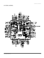
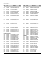
Exploded View and Parts List
T220
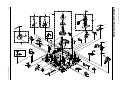
6-2 Mechanical Parts (Top Side)
6-4
919
Exploded View and Parts List
Loc. No
Part No
Description and Specification
Remark
900
901
919
920
952
956
957
T201
T202
T203
T204
T207
T208
T209
T210
T211
T212
T216
T217
T218
T219
T220
T221
T222
T223
T224
T225
T226
T227
T228
T229
T230
T231
T232
T233
T234
T236
T238
T239
T240
T300
AC60-12091A
AC60-10012A
AC60-10004A
AC60-10007A
AC60-30018A
AC60-30007A
AC60-30008A
AC66-10023A
AC66-10022A
AC66-30474A
AC66-30148A
AC66-30475A
AC66-30476A
AC61-60112A
AC66-20073A
AC66-20037A
AC66-30073A
AC61-60119A
AC66-30470A
AC61-62017A
AC33-10003P
AC66-82050A
AC66-82054A
AC33-10002E
AC66-20065A
AC33-10216K
AC66-80005A
AC66-30014A
AC66-30099A
AC66-30013A
AC66-30003A
AC61-60116A
AC67-32001A
AC66-82049A
AC61-62016A
AC59-90402A
AC66-10010A
AC61-60132A
AC66-30132A
AC61-60505A
AC96-10475L
AC96-10475K
SCREW-MACHINE;FP,BH,-,M3,L4,SWRCH10A,YEL ROB
SCREW-MACHINE;BH,+,M3,L8,-,FE,-,-,SCREW-MACHINE;BH,+,M3,L8,ZPC,SWRCH18A,-,
SCREW-TAPPING;BH,+,M2.6,L12,-,SWRCH18A,WASHER-PLAIN;PLAIN,M3.2,D6,T0.5,POLYSLID
WASHER-SLIT;PLAIN,ID2.5,OD7,T0.5,SPC1,-,
WASHER-SLIT;-,ID3.5,OD9,T0.5,SPC1,-,REEL-DISK L ASSY;POM,-,PACKAGE,X-5,REEL-DISK R (ASSY);POM,-,PACKAGE,X-5,BRAKE-SUB L;-,PBT,-,-,-,X-5/IS
BRAKE SUB R;-,-,-,-,X5,BRAKE-MAIN L ASS’Y;-,POM+PELT,-,-,-,X-5/
BRAKE-MAIN R ASS’Y;-,POM+PELT,-,-,-,X-5/
SPRING- BRAKE MAIN;ES,SUS304WPB,PI0.35,I
GEAR RELAY S-ASSY;-,-,-,-,-,X5,GEAR- RELAY T;PEBAX7033,X-5,Z39,GEAR-SPU
ARM-TENSION ASSY;-,DX5-R,-,-,-,SPRING TENSION;ES,SWPB,PI0.4,D3,L33(OD3.
LEVER-REC S/W;-,PBT #3300,T4.0,L32,-,(XSPRING-SUB BRAKE L;ES,SUS304,PI0.23,D3.5
HEAD- MAGNET F/E;MH131S,-,-,-,L51.05XW7.
SLIDER-G/R ASSY(S);-,-,-,-,X-5
SLIDER-G/R ASSY(T);-,-,-,-,X-5
HEAD-CLEANER;-,-,-,X-5
RACK-HOUSING;L74.29,POM M90-44,BLK,M1,3.
HEAD-ACE ALL ASSY;-,-,-,-,X-7A
SLIDER-PINCH;POM(M90-44),T10.5,L54.35,NA
LEVER-REVIEW;ZYTEL(70G-43L),T5,-,PCD25.6
ARM-REVIEW ASSY;-,-,-,-,DX5-R,LEVER- CAM;PBT 6300T,-,L45,W9,X-5,LEVER-PINCH COMP;PBT 3300,T7.5,L45.25,-,
SPRING- PINCH COMP;TS,SWPB,PI1.0,D6,L38(
PRISM-LED;PMMA,D5,IF-850,-,-,SLIDER-PUSH;LUPOX 2150,T2,-,NTR,SPRING-SLIDE PUSH;ES,SUS304WPB,PI0.55,D3
UNIT-PINCH ROLLER;X-7A,RESIN BEARING
IDLER-ASSY;PACKAGE,-,X-5,SPRING ARM PINCH;CS,SUS304WPB,PI0.4,D7.1
LEVER JOG-ASS’Y;-,-,-,X-5
SPRING-REC S/W;-,ES,SUS304 WPB,PI0.29,PI
ASSY-CYLINDER;CX8A-H6P
ASSY-CYLINDER;CX8A-H6P/DLC
(OPTIONAL)
Samsung Electronics
(OPTIONAL)
(OPTIONAL)
(NON-DLC)
(DLC)
6-5
B256
956
902
958
951
B255
B258
B254
B261
922
B263
B251
952
B268
B267
B266
B265
B259
B253
B260
G
951
B252
G
O
G
B264
B262
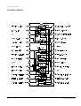
Samsung Electronics
918
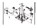
Exploded View and Parts List
6-3 Mechanical Parts (Bottom Side)
6-6
B257
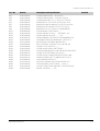
Exploded View and Parts List
Loc. No
Part No
Description and Specification
902
918
922
951
952
956
958
B251
B252
B253
B254
B255
B256
B257
B258
B259
B260
B261
B262
B263
B264
B265
B266
B267
B268
AC60-10051A
AC60-10041A
AC60-10504A
AC60-30025A
AC60-30018A
AC60-30007A
AC60-30028A
AC66-82043A
AC66-20019A
AC66-20069A
AC61-60115A
AC66-20004A
AC31-12006A
AC66-62008A
AC66-20066A
AC66-32185A
AC66-20016A
AC66-30011A
AC66-30012A
AC61-60111A
AC59-90001A
AC31-12015A
AC66-20039A
AC61-20224A
AC66-30149A
SCREW-TAPPING;BH,-,-,M3,L8,FZY
SCREW-TAPPING;BH,+,-,M2.6XL7.5,ZPC3
SCREW-MACHINE;-,PH,+,-,M3,L3,FE,FZY,YEL
WASHER-SLIT;-,ID2.5,OD5.0,T0.5,POLY SLID
WASHER-PLAIN;PLAIN,M3.2,D6,T0.5,POLYSLID
WASHER-SLIT;PLAIN,ID2.5,OD7,T0.5,SPC1,-,
WASHER-SLIT;-,D2.5,D9.0,T0.5,NUMIRROR,-,
SLIDER-MAIN;TOPEX 4010S,-,-,-,GEAR-LOADING L ASSY;-,-,-,PACKAGE,-,X-5,
GEAR-LOADING R ASSY;-,-,-,-,-,X5,SPRING-BRAKE CAPSTAN;ES,SUS304WPB,PI0.4,
GEAR-MASTER;POM (M90-44),M 1,Z 60,SP,-,X
MOTOR-D/D CAPSTAN;DMVCMC07A,-,BELT-CAPSTAN;-,DLB-601,T2,8,L134.9,BLK,X
GEAR-CLUTCH ASSY;X-5,-,-,-,-,-,LEVER-SLIDER PINCH;PBT,T4,NAT,-,-,GEAR- WORM WHEEL;POM SW-01,M0.55/M1,Z57/
LEVER- SHIFT;PBT2002K,T10.9,L35,-,-,LEVER- IDELR CHANGE;PBT330,T33,L50,-,W6.
SPRING-LEVER SHIFT;TS,SWPB,PI0.7,D5.5,L1
UNIT-LOADING ASSY;X-5,-,MOTOR-LOADING ASSY;POM+RF370C X-5
GEAR- WORM LO;PBT 2002K,-,-,-,D4.5,3,HOLDER SHAFT;POM M90-44,T1.25,NTR,PI5XH5
BRAKE CAPSTAN;-,-,-,-,X5,-
Samsung Electronics
Remark
6-7
Exploded View and Parts List
6-4 Housing Assembly
914
902
H510
902
H520
H521
H533
H522
H530
H532
H526
H524
H531
914
H535
H540
914
H545
H544
H550
H541
H542
H500
H543
Loc. No
Part No
Description and Specification
902
914
H500
H510
H520
H521
H522
H524
H526
H530
H531
H532
H533
H535
H540
H541
H542
H543
H544
H545
H550
AC60-10051A
AC60-10067A
AC61-82014D
AC61-10006A
AC61-20932B
AC61-20922B
AC66-30018A
AC61-60121A
AC66-30019A
AC61-11033A
AC61-10004A
AC66-30004A
AC61-60142A
AC66-30017A
AC61-11032A
AC61-10003A
AC66-80008A
AC61-60120A
AC66-30016A
AC61-60123A
AC61-50654A
SCREW-TAPPING;BH,-,-,M3,L8,FZY
SCREW-TAPTITE;PWH,+,-,M3,L8,MFZN2-C,SWCH
HOUSING-ASSY;-,X7FL26280B,230X130X60,-,X
CHASSIS- UPPER;SECC 20/20,-,T1.0,BLK,-,X
HOLDER-CASSETTE ASSY;-,X5FL06080A,-,-,-,
HOLDER-CASSETTE;-,SECC T1.2,-,NAT,-,X-7(
LEVER-LOCK R;SECC 20/20,T1.2,L44,W32,-,SPRING-LEVER LOCK;ES,SUS304 WPB,PI0.2,D2
LEVER-KEY CASSETTE;LUCEL N109-LD,T2.5,L2
CHASSIS-SIDE L ASSY;-,-,-,-,-,X5FL0505A,
CHASSIS- SIDE L;ABS HF-380,-,T10,BLK,-,X
LEVER- LIGHT SHUTTER;LUCEL N109-LD,T2.5,
SPRING- LIGHT;ES,SUS304WPB,PI0.2,L11.4(O
LEVER- DOOR;LUCELN109-LD,T3.5,L74.3,W21.
CHASSIS-SIDE R ASSY;-,-,-,-,-,X5FL0505A,
CHASSIS- SIDE R;ABS HF-380,-,T10,BLK,-,X
SLIDER DAMPER;LUCEL N109-LD,T4,L87,-,-,SPRING-SLIDER;ES,SUS 304WPB,PI0.4,D3.8,L
LEVER- LID OPENER;LUCEL N109-LD,T4.0,L34
SPRING-LID OPENER;TS,SWPB,PI0.55,D8.9,L1
SHAFT-ARM ASSY;-,SUM24L,-,-,-,-,X-5
6-8
Remark
Samsung Electronics
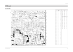
7. Electrical Parts List
Loc.No
Part No
-
Desc and Spec
ASSY-MAIN;C2 PAL HI-FI
Remark
Loc.No
Part No
Desc and Spec
S.N.A
A1151-0042
AC27-92001M
AC27-92001M
AC27-12001N
AC27-12001N
COIL-LINE FILTER;BSF-2120Z 25MH 3.2OHM
INDUCTOR;70UH-M RT BFS3565R2F,-,-,-,INDUCTOR;70UH-M RT BFS3565R2F,-,-,-,COIL-CHOKE;10UH-15%,RA,K-30,Q80,150KHZ,COIL-CHOKE;10UH-15%,RA,K-30,Q80,150KHZ,-
SMPS/POWER PARTS
C1P01
2401-001952
C1P02
2301-000383
C-AL;4.7UF,20%,50V,-,TP,6.3X7,5
C-FILM,PEF;10nF,5%,50V,6x7x3.2mm,5mm,TP
L1S02
L1S04
L1S05
L1S30
L1S31
C1P03
C1P04
C1P05
C1P06
C1P09
2203-001724
2401-001975
2401-001978
2401-001915
2401-001912
C-CERAMIC,CHIP;4.7UF,+80-20%,16V,Y5V,321
C-AL;47UF,20%,16V,GP,TP,5X11MM,5
C-AL;47UF,20%,25V,GP,TP,6.3X5,5
C-AL;1uF,20%,50V,GP,TP,3x5,1mm
C-AL;1uF,20%,50V,GP,5x11mm,2mm,BK
L1S32
L1S33
PT1S01
PT601
PT602
AC27-92001M
AC27-92001M
AC26-20120A
0604-000188
0604-000188
INDUCTOR;70UH-M RT BFS3565R2F,-,-,-,INDUCTOR;70UH-M RT BFS3565R2F,-,-,-,TRANS-SWITCHING;-,220V,UL/CSA,-,1000UH,PHOTO-INTERRUPTER;TR,-,-,DIP-4,TR
PHOTO-INTERRUPTER;TR,-,-,DIP-4,TR
C1P10
C1S03
C1S04
C1S05
C1S06
2202-000797
2305-001021
2305-001021
2201-000808
2201-000934
C-CERAMIC,MLC-AXIAL;10NF,30%,16V,Y5P,TP,
C-FILM,MPEF;100nF,20%,275V,TP,17.5x7x13.
C-FILM,MPEF;100nF,20%,275V,TP,17.5x7x13.
C-CERAMIC,DISC;2.2nF,10%,400V,Y5P,12x7.5
C-CERAMIC,DISC;3.3nF,20%,400V,Y5P,18x8,1
Q1P01
Q1P02
Q1P03
Q1P04
Q1P05
0501-000610
0504-000116
0501-000610
0504-000118
0501-000616
TR-SMALL SIGNAL;KSA928A-Y,PNP,1W,TO-92L,
TR-DIGITAL;KSR1001,NPN,300mW,4.7K-4.7K,T
TR-SMALL SIGNAL;KSA928A-Y,PNP,1W,TO-92L,
TR-DIGITAL;KSR1003,NPN,300mW,22K-22K,TOTR-SMALL SIGNAL;KSC2328A-Y,NPN,1W,TO-92L
C1S08
C1S08
C1S09
C1S10
C1S15
2401-003302
2401-003303
2201-000934
2201-000915
2301-000224
C-AL;47uF,20%,400V,GP,TP,18X31.5,7.
C-AL;82uF,20%,400V,GP,TP,18X31.5,7.
C-CERAMIC,DISC;3.3nF,20%,400V,Y5P,18x8,1
C-CERAMIC,DISC;100pF,10%,1KV,Y5P,TP,6x5,
C-FILM,PEF;22nF,5%,50V,TP,7.4x3.9x13mm
Q1P06
Q1P07
Q1S01
R1P01
R1P02
0501-000616
0501-000398
AC93-10840R
2004-001096
2004-001096
TR-SMALL SIGNAL;KSC2328A-Y,NPN,1W,TO-92L
TR-SMALL SIGNAL;KSC945,NPN,250mW,TO-92,T
ASSY-MAIN,MANU;SV-B120F/SEF,C2 PAL HI-FI
R-METAL;560ohm,5%,1/4W,AA,TP,2.4X6.4mm
R-METAL;560ohm,5%,1/4W,AA,TP,2.4X6.4mm
C1S16
C1S17
C1S18
C1S19
C1S30
2201-000795
2401-000970
2301-000224
2401-001912
2401-000385
C-CERAMIC,DISC;10nF,10%,400V,Y5P,15x10,5
C-AL;22uF,20%,50V,WT,TP,5x11,2mm
C-FILM,PEF;22nF,5%,50V,TP,7.4x3.9x13mm
C-AL;1uF,20%,50V,GP,5x11mm,2mm,BK
C-AL;10UF,20%,100V,GP,-,6.3X11,2.5M
R1P03
R1P04
R1P05
R1P06
R1P07
2001-000273
2001-000611
2001-000449
2001-000429
2007-001637
R-CARBON;100Kohm,5%,1/8W,AA,TP,1.8x3.2m
R-CARBON;3.9Kohm,5%,1/4W,AA,TP,2.4x6.4m
R-CARBON;2.2Kohm,5%,1/8W,AA,TP,1.8x3.2m
R-CARBON;1Kohm,5%,1/8W,AA,TP,1.8x3.2mm
R-CHIP,MELF;1.2Kohm,5%,1/8W,DB,BK,2012
C1S31
C1S32
C1S33
C1S34
C1S35
2401-001134
2401-001998
2401-001125
2401-001992
2401-001355
C-AL;330UF,20%,35V,WT,TP,10X16,5MM
C-AL;1000uF,20%,25V,GP,TP,10x20,5mm
C-AL;330UF,20%,25V,WT,TP,10X12.5,5M
C-AL;2200uF,20%,10V,GP,10x20mm,5mm,
C-AL;470UF,20%,10V,GP,-,8X11.5,5MM
R1P09
R1P10
R1S02
R1S03
R1S06
2004-000571
2001-000449
2003-000273
2001-000076
2003-000273
R-METAL;220ohm,5%,1/4W,AA,TP,2.4x6.4mm
R-CARBON;2.2Kohm,5%,1/8W,AA,TP,1.8x3.2m
R-METAL OXIDE;33Kohm,5%,2W,AA,TP,6x16mm
R-CARBON;47Kohm,5%,1/4W,AA,TP,2.4x6.4mm
R-METAL OXIDE;33Kohm,5%,2W,AA,TP,6x16mm
C1S38
C1S99
CN1S1
D1P01
D1P02
2301-000129
2301-000423
3711-000178
0402-000132
0402-000132
C-FILM,PEF;100nF,5%,50V,10X9X4.3X5,5mm,T
C-FILM,PEF;3.3NF,5%,100V,TP,7X10X4.5MM,5
CONNECTOR-HEADER;1WALL,2P,1R,3.96mm,STRA
DIODE-RECTIFIER ;1N4004,400V,1A,DO-41
DIODE-RECTIFIER ;1N4004,400V,1A,DO-41
R1S07
R1S11
R1S12
R1S13
R1S14
2001-000302
2006-000262
2001-000076
2001-000076
2001-000076
R-CARBON;10ohm,5%,1/8W,AA,TP,1.8x3.2mm
R-CEMENT;2.7ohm,10%,2W,CB,ST,7.5x11x20.
R-CARBON;47Kohm,5%,1/4W,AA,TP,2.4x6.4mm
R-CARBON;47Kohm,5%,1/4W,AA,TP,2.4x6.4mm
R-CARBON;47Kohm,5%,1/4W,AA,TP,2.4x6.4mm
D1P03
D1P04
D1P06
D1P20
D1S01
0402-000132
0402-000132
0401-000101
0402-000132
0402-001009
DIODE-RECTIFIER ;1N4004,400V,1A,DO-41
DIODE-RECTIFIER ;1N4004,400V,1A,DO-41
DIODE-SWITCHING;1N4148,100V,200mA,500mW,
DIODE-RECTIFIER ;1N4004,400V,1A,DO-41
DIODE-RECTIFIER;1SR139,600V,1A,MSR
R1S15
R1S30
R1S31
R1S32
R1S33
2003-000148
2001-000515
2001-000221
2001-000429
2004-000869
R-METAL OXIDE;100OHM,5%,2W,AE,TP,6X16MM
R-CARBON;220ohm,5%,1/8W,AA,TP,1.8x3.2mm
R-CARBON;1.2Kohm,5%,1/8W,AA,TP,1.8x3.2m
R-CARBON;1Kohm,5%,1/8W,AA,TP,1.8x3.2mm
R-METAL;3Kohm,1%,1/8W,AA,TP,1.8x3.2mm
D1S02
D1S03
D1S04
D1S05
D1S07
0402-001009
0402-001009
0402-001009
0402-000378
0402-001013
DIODE-RECTIFIER;1SR139,600V,1A,MSR
DIODE-RECTIFIER;1SR139,600V,1A,MSR
DIODE-RECTIFIER;1SR139,600V,1A,MSR
DIODE-RECTIFIER;EG01C,1000V,500mA,DO-41
DIODE-RECTIFIER;1SR153-400,400V,800mA,DO
R1S34
VA1S01
VA1S02
ZD1P01
ZD1P02
2004-000459
1405-000186
1405-000186
0403-000390
0403-000717
R-METAL;2.2Kohm,1%,1/8W,AA,TP,1.
VARISTOR;470V,4500A,17x12mm,TP
VARISTOR;470V,4500A,17x12mm,TP
DIODE-ZENER;UZP33B,33V,31.4-34.6V,1W,DODIODE-ZENER;MTZJ5.1B,5.1V,4.94-5.2V,500m
D1S30
D1S31
D1S33
D1S43
F1S01
0402-001013
0402-001013
0402-000431
0402-001069
A3065-0157
DIODE-RECTIFIER;1SR153-400,400V,800mA,DO
DIODE-RECTIFIER;1SR153-400,400V,800mA,DO
DIODE-RECTIFIER;FML-M02S,200V,2.5A,TO-22
DIODE-RECTIFIER;RL10Z,200V,2A,DO,TP
FUSE;FST 250V 1.6A 20MM SEMKO S505 C
ZD1S01
ZD1S2
0403-000539
0403-000294
DIODE-ZENER;MTZ18C,18V,17.42-18.33V,500m
DIODE-ZENER;MTZ4.7B,4.55-4.80V,500mW,DO-
IC1P01
IC1S1
IC1S2
IC1S3
L1S01
AC14-12001E
1203-001049
0604-011028
AC14-12006D
AC29-30050A
IC;KA7809,-,IC-PWM CONTROLLER:1L0380,TO-220F,4P,10MI
PHOTO-COUPLER;PS2561-1 ST DIP
IC;KA431Z,TO-92,TAPING
FILTER-LINE NOISE;-,400UH,-,250V,-
C602
C603
C604
C605
C606
Samsung Electronics
230V ONLY
FREE VOLT
Remark
SYSTEM CONTOL/SERVO PARTS
C601
2203-002188
C-CERAMIC,CHIP;10NF,+80-20%,16V,Y5V,TP,2
2202-000807
2203-001557
2203-002188
2202-000791
2202-000797
C-CERAMIC,MLC-AXIAL;22NF,+80-20%,25V,Y5V
C-CERAMIC,CHIP;100NF,+80-20%,25V,Y5V,TP,
C-CERAMIC,CHIP;10NF,+80-20%,16V,Y5V,TP,2
C-CERAMIC,MLC-AXIAL;150PF,10%,50V,Y5P,TP
C-CERAMIC,MLC-AXIAL;10NF,30%,16V,Y5P,TP,
7-1
Electrical Parts List
Loc.No
Part No
Desc and Spec
Remark
Loc.No
Part No
C607
C608
C609
C610
C6101
2203-002188
2203-001557
2203-001679
2203-001679
2202-000780
C-CERAMIC,CHIP;10NF,+80-20%,16V,Y5V,TP,2
C-CERAMIC,CHIP;100NF,+80-20%,25V,Y5V,TP,
C-CERAMIC,CHIP;68NF,+80-20%,25V,Y5V,TP,2
C-CERAMIC,CHIP;68NF,+80-20%,25V,Y5V,TP,2
C-CERAMIC,MLC-AXIAL;100nF,+80-20%,50V,Y5
C677
C678
C679
C681
C682
2202-000797
2401-001915
2202-000807
2203-001557
2202-000780
C-CERAMIC,MLC-AXIAL;10NF,30%,16V,Y5P,TP,
C-AL;1uF,20%,50V,GP,TP,3x5,1mm
C-CERAMIC,MLC-AXIAL;22NF,+80-20%,25V,Y5V
C-CERAMIC,CHIP;100NF,+80-20%,25V,Y5V,TP,
C-CERAMIC,MLC-AXIAL;100nF,+80-20%,50V,Y5
C6102
C6103
C6104
C6105
C6106
2203-000239
2202-000216
2202-000216
2203-002188
2301-000392
C-CERAMIC,CHIP;100pF,5%,50V,NPO,TP,2012,
C-CERAMIC,MLC-AXIAL;27pF,5%,50V,SL,TP,3.
C-CERAMIC,MLC-AXIAL;27pF,5%,50V,SL,TP,3.
C-CERAMIC,CHIP;10NF,+80-20%,16V,Y5V,TP,2
C-FILM,PEF;15nF,5%,50V,6.5x8.5x3.2mm,5mm
C698
CN601
CN602
CN603
CN604
2203-001557
3708-001251
3711-002445
3711-003749
3708-001165
C-CERAMIC,CHIP;100NF,+80-20%,25V,Y5V,TP,
CONNECTOR-FPC/FC/PIC;22P,1mm,STRAIGHT-F,
CONNECTOR-HEADER;BOX,2P,2R,1.5MM,STRAIGH
CONNECTOR-HEADER;BOX,8P,2R,2mm,STRAIGHT,
CONNECTOR-FPC/FC/PIC;6P,1.25mm,STRAIGHT,
C6107
C611
C6114
C6116
C6117
2203-000818
2201-000928
2201-000800
2203-001612
2203-001612
C-CERAMIC,CHIP;33pF,5%,50V,NPO,TP,2012,C-CERAMIC,DISC;2.7NF,20%,16V,Y5R,TP,3.5X
C-CERAMIC,DISC;120PF,5%,50V,SL,TP,5X3,5
C-CERAMIC,CHIP MELF;22PF,5%,50V,SL,TP,20
C-CERAMIC,CHIP MELF;22PF,5%,50V,SL,TP,20
D605
D608
D609
D6102
D6104
0402-000132
0401-000101
0401-000101
0401-000101
0401-000101
DIODE-RECTIFIER ;1N4004,400V,1A,DO-41
DIODE-SWITCHING;1N4148,100V,200mA,500mW,
DIODE-SWITCHING;1N4148,100V,200mA,500mW,
DIODE-SWITCHING;1N4148,100V,200mA,500mW,
DIODE-SWITCHING;1N4148,100V,200mA,500mW,
C6119
C612
C6120
C6122
C6123
2401-001975
2202-000791
2202-000780
2401-001952
2401-001978
C-AL;47UF,20%,16V,GP,TP,5X11MM,5
C-CERAMIC,MLC-AXIAL;150PF,10%,50V,Y5P,TP
C-CERAMIC,MLC-AXIAL;100nF,+80-20%,50V,Y5
C-AL;4.7UF,20%,50V,-,TP,6.3X7,5
C-AL;47UF,20%,25V,GP,TP,6.3X5,5
D6105
D6106
D611
D612
D613
0401-000101
0401-000101
0402-000132
0402-000132
0402-000132
DIODE-SWITCHING;1N4148,100V,200mA,500mW,
DIODE-SWITCHING;1N4148,100V,200mA,500mW,
DIODE-RECTIFIER ;1N4004,400V,1A,DO-41
DIODE-RECTIFIER ;1N4004,400V,1A,DO-41
DIODE-RECTIFIER ;1N4004,400V,1A,DO-41
C6124
C6125
C6126
C6127
C613
2401-001325
2203-002188
2401-000419
2203-001659
2203-001557
C-AL;470nF,20%,50V,GP,TP,3x5,5
C-CERAMIC,CHIP;10NF,+80-20%,16V,Y5V,TP,2
C-AL;10UF,20%,16V,GP,-,4X7,5
C-CERAMIC,CHIP MELF;47PF,5%,50V,SL,TP,20
C-CERAMIC,CHIP;100NF,+80-20%,25V,Y5V,TP,
D614
D615
IC601
0401-000101
DIODE-SWITCHING;1N4148,100V,200mA,500mW,
0401-000101
DIODE-SWITCHING;1N4148,100V,200mA,500mW,
Refer to table below IC-MCU;100P,QFP
Country
Desc and Spec
Part No
Remark
Specification
C614
C615
C616
C617
C618
2203-002188
2203-002188
2203-001696
2202-000796
2203-001702
C-CERAMIC,CHIP;10NF,+80-20%,16V,Y5V,TP,2
C-CERAMIC,CHIP;10NF,+80-20%,16V,Y5V,TP,2
C-CERAMIC,CHIP MELF;82PF,10%,50V,Y5P,TP,
C-CERAMIC,MLC-AXIAL;UP050 B102KB INF,10%
C-CERAMIC,CHIP;2.2nF,5%,50V,X7R,2012,-,T
C619
C620
C623
C624
C625
2203-001696
2203-001696
2203-001580
2203-001580
2203-001580
C-CERAMIC,CHIP MELF;82PF,10%,50V,Y5P,TP,
C-CERAMIC,CHIP MELF;82PF,10%,50V,Y5P,TP,
C-CERAMIC,CHIP MELF;15PF,5%,50V,SL,TP,20
C-CERAMIC,CHIP MELF;15PF,5%,50V,SL,TP,20
C-CERAMIC,CHIP MELF;15PF,5%,50V,SL,TP,20
Italy/Spain/Portugal/U.K
AC09-10457Y
HD6433977RB19F
Germany/Austria/Switzerlands
AC09-10458K
HD6433977RB15F
France/Netherlands/Belgium/Denmark
AC09-10457X
HD6433977RB18F
Finland/Sweeden/Norway
Saudi Arabia/Lebanon
AC09-10457Z
HD6433977RB17F
Australia/New Zealand
IC602
1003-001090
IC-MOTOR DRIVER;LB1643,SIP,10P,-,SINGLE,
IC603
1201-000230
IC-OP AMP;6324,DIP,14P,-,QUAD,15/100mV,P
IC604
AC14-12006C
IC;KA7533,DIP,IC605
1103-001020
IC-EEPROM;24LC04,4Kx8BIT,DIP,8P,300MIL,IC606
AC14-12009E
IC;HCF4094BE/TC4094BP,DIP,LOGIC
C626
C627
C628
C630
C632
2203-001580
2202-000807
2202-000807
2202-000780
2401-001511
C-CERAMIC,CHIP MELF;15PF,5%,50V,SL,TP,20
C-CERAMIC,MLC-AXIAL;22NF,+80-20%,25V,Y5V
C-CERAMIC,MLC-AXIAL;22NF,+80-20%,25V,Y5V
C-CERAMIC,MLC-AXIAL;100nF,+80-20%,50V,Y5
C-AL;47UF,20%,16V,GP,-,6X7,5
J602
L601
L602
L603
L604
2007-001589
AC27-92001B
AC27-92001B
AC27-92001B
2701-000131
R-CHIP,MELF;1Kohm,5%,1/8W,DB,BK,2012
COIL-PEAKING AXIAL;BAL04ST101K,-,-,-,COIL-PEAKING AXIAL;BAL04ST101K,-,-,-,COIL-PEAKING AXIAL;BAL04ST101K,-,-,-,INDUCTOR-AXIAL;15UH,5%,2.4X3.4MM
C633
C634
C635
C636
C637
2401-001904
2401-000208
2401-000199
2401-001978
2401-001978
C-AL;10UF,20%,16V,-,TP,4X7MM,5
C-AL;100nF,+80-20%,5.5V,GP,TP,12.3m
C-AL;1000UF,20%,6.3V,GP,TP,10X12.5,
C-AL;47UF,20%,25V,GP,TP,6.3X5,5
C-AL;47UF,20%,25V,GP,TP,6.3X5,5
L605
L606
L6101
L6103
LD601
AC27-92001B
3301-000297
AC27-92001B
2701-000117
0601-000495
COIL-PEAKING AXIAL;BAL04ST101K,-,-,-,CORE-FERRITE BEAD;AA,3.6x1.2x5.7mm,1400,
COIL-PEAKING AXIAL;BAL04ST101K,-,-,-,INDUCTOR-AXIAL;10uH,5%,2.4x3.4mm
LED-IR;ROUND,3mm,150mW,6V,950nm,BK
C638
C639
C640
C642
C643
2401-001915
2401-001904
2401-001978
2401-000918
2401-000918
C-AL;1uF,20%,50V,GP,TP,3x5,1mm
C-AL;10UF,20%,16V,-,TP,4X7MM,5
C-AL;47UF,20%,25V,GP,TP,6.3X5,5
C-AL;22uF,20%,16V,GP,-,6.3x7,5
C-AL;22uF,20%,16V,GP,-,6.3x7,5
Q601
Q602
Q604
Q607
Q608
0501-000398
0501-000398
0501-000303
0504-000142
0504-000203
TR-SMALL SIGNAL;KSC945,NPN,250mW,TO-92,T
TR-SMALL SIGNAL;KSC945,NPN,250mW,TO-92,T
TR-SMALL SIGNAL;KSA733-Y,PNP,250mW,TO-92
TR-DIGITAL;KSR2001,PNP,300mW,4.7K-4.7K,T
TR-DIGITAL;KSR1004,NPN,300mW,47K-47K,TO-
C645
C650
C651
C652
C660
2203-000477
2203-002188
2401-001511
2202-000780
2203-001702
C-CERAMIC,CHIP;1uF,+80-20%,16V,Y5V,TP,20
C-CERAMIC,CHIP;10NF,+80-20%,16V,Y5V,TP,2
C-AL;47UF,20%,16V,GP,-,6X7,5
C-CERAMIC,MLC-AXIAL;100nF,+80-20%,50V,Y5
C-CERAMIC,CHIP;2.2nF,5%,50V,X7R,2012,-,T
Q609
Q6101
Q6102
Q6106
Q6108
AC14-12001G
0501-000398
0501-000398
0501-000398
0501-000303
IC;KA78L05,T,TR-SMALL SIGNAL;KSC945,NPN,250mW,TO-92,T
TR-SMALL SIGNAL;KSC945,NPN,250mW,TO-92,T
TR-SMALL SIGNAL;KSC945,NPN,250mW,TO-92,T
TR-SMALL SIGNAL;KSA733-Y,PNP,250mW,TO-92
C661
C663
C671
C675
C676
2203-001702
2203-000374
2203-001557
2401-001975
2202-000797
C-CERAMIC,CHIP;2.2nF,5%,50V,X7R,2012,-,T
C-CERAMIC,CHIP;15nF,10%,50V,X7R,TP,2012,
C-CERAMIC,CHIP;100NF,+80-20%,25V,Y5V,TP,
C-AL;47UF,20%,16V,GP,TP,5X11MM,5
C-CERAMIC,MLC-AXIAL;10NF,30%,16V,Y5P,TP,
R601
R602
R604
R605
R606
2001-000832
2001-000679
2007-001472
2007-001589
2007-000658
R-CARBON;510ohm,5%,1/8W,AA,TP,1.8x3.2mm
R-CARBON;36KOHM,5%,1/8W,AA,TP,1.8X3.2MM
R-CHIP,MELF;68KOHM,5%,1/8W,DB,BK,2012
R-CHIP,MELF;1Kohm,5%,1/8W,DB,BK,2012
R-CHIP;27ohm,5%,1/10W,DA,TP,2012
7-2
Samsung Electronics
Electrical Parts List
Loc.No
Part No
Desc and Spec
R607
R608
R610
R6100
R6101
2007-001589
2007-001637
2001-000947
2001-000613
2007-001629
R-CHIP,MELF;1Kohm,5%,1/8W,DB,BK,2012
R-CHIP,MELF;1.2Kohm,5%,1/8W,DB,BK,2012
R-CARBON;7.5KOHM,5%,1/8W,AA,TP,1.8X3.2M
R-CARBON
;3.9K OHM,5%,1/8,AA,T
R-CHIP,MELF;1.8Kohm,5%,1/8W,DB,BK,2012
R645
R646
R647
R648
R649
2001-000429
2001-000347
2001-000347
2007-001589
2001-000429
R-CARBON;1Kohm,5%,1/8W,AA,TP,1.8x3.2mm
R-CARBON;13Kohm,5%,1/8W,AA,TP,1.8x3.2mm
R-CARBON;13Kohm,5%,1/8W,AA,TP,1.8x3.2mm
R-CHIP,MELF;1Kohm,5%,1/8W,DB,BK,2012
R-CARBON;1Kohm,5%,1/8W,AA,TP,1.8x3.2mm
R6102
R6103
R6104
R6105
R6106
2007-001497
2001-000290
2007-001507
2001-000429
2007-001586
R-CHIP,MELF;5.6KOHM,5%,1/8W,DB,BK,2012
R-CARBON;10Kohm,5%,1/8W,AA,TP,1.8x3.2mm
R-CHIP,MELF;470KOHM,5%,1/8W,DB,BK,2012
R-CARBON;1Kohm,5%,1/8W,AA,TP,1.8x3.2mm
R-CHIP,MELF;1Mohm,5%,1/8W,DB,BK,2012
R651
R652
R653
R654
R655
2001-000786
2001-000429
2001-000864
2001-000864
2001-000429
R-CARBON;47Kohm,5%,1/8W,AA,TP,1.8x3.2mm
R-CARBON;1Kohm,5%,1/8W,AA,TP,1.8x3.2mm
R-CARBON;56Kohm,5%,1/8W,AA,TP,1.8x3.2mm
R-CARBON;56Kohm,5%,1/8W,AA,TP,1.8x3.2mm
R-CARBON;1Kohm,5%,1/8W,AA,TP,1.8x3.2mm
R6107
R6109
R6110
R6111
R6112
2001-000429
2001-000241
2007-001503
2007-001497
2001-000281
R-CARBON;1Kohm,5%,1/8W,AA,TP,1.8x3.2mm
R-CARBON;1.5Kohm,5%,1/8W,AA,TP,1.8x3.2m
R-CHIP,MELF;47KOHM,5%,1/8W,DB,BK,2012
R-CHIP,MELF;5.6KOHM,5%,1/8W,DB,BK,2012
R-CARBON;100ohm,5%,1/8W,AA,TP,1.8x3.2mm
R656
R657
R658
R659
R660
2001-000429
2001-000429
2001-000429
2001-000449
2001-000281
R-CARBON;1Kohm,5%,1/8W,AA,TP,1.8x3.2mm
R-CARBON;1Kohm,5%,1/8W,AA,TP,1.8x3.2mm
R-CARBON;1Kohm,5%,1/8W,AA,TP,1.8x3.2mm
R-CARBON;2.2Kohm,5%,1/8W,AA,TP,1.8x3.2m
R-CARBON;100ohm,5%,1/8W,AA,TP,1.8x3.2mm
R6113
R6115
R6116
R6117
R6119
2001-000660
2007-001589
2001-001031
2001-000850
2001-000864
R-CARBON;33Kohm,5%,1/8W,AA,TP,1.8x3.2mm
R-CHIP,MELF;1Kohm,5%,1/8W,DB,BK,2012
R-CARBON;91KOHM,5%,1/8W,AA,TP,1.8X3.2MM
R-CARBON;560Kohm,5%,1/8W,AA,TP,1.8x3.2m
R-CARBON;56Kohm,5%,1/8W,AA,TP,1.8x3.2mm
R661
R662
R663
R664
R665
2001-000429
2001-000429
2001-000429
2001-000429
2001-000362
R-CARBON;1Kohm,5%,1/8W,AA,TP,1.8x3.2mm
R-CARBON;1Kohm,5%,1/8W,AA,TP,1.8x3.2mm
R-CARBON;1Kohm,5%,1/8W,AA,TP,1.8x3.2mm
R-CARBON;1Kohm,5%,1/8W,AA,TP,1.8x3.2mm
R-CARBON;150ohm,5%,1/8W,AA,TP,1.8x3.2mm
R612
R6120
R6121
R6122
R6123
2001-000539
2007-001586
2001-000429
2007-001623
2007-001503
R-CARBON;24Kohm,5%,1/8W,AA,TP,1.8x3.2mm
R-CHIP,MELF;1Mohm,5%,1/8W,DB,BK,2012
R-CARBON;1Kohm,5%,1/8W,AA,TP,1.8x3.2mm
R-CHIP,MELF;10Kohm,5%,1/8W,DB,BK,2012
R-CHIP,MELF;47KOHM,5%,1/8W,DB,BK,2012
R666
R667
R668
R669
R670
2001-000429
2001-000429
2001-000362
2001-000290
2001-000012
R-CARBON;1Kohm,5%,1/8W,AA,TP,1.8x3.2mm
R-CARBON;1Kohm,5%,1/8W,AA,TP,1.8x3.2mm
R-CARBON;150ohm,5%,1/8W,AA,TP,1.8x3.2mm
R-CARBON;10Kohm,5%,1/8W,AA,TP,1.8x3.2mm
R-CARBON;680Kohm,5%,1/8W,AA,TP,1.8x3.2m
R6124
R6125
R6128
R6129
R6130
2001-000633
2001-000633
2001-000534
2001-000281
2001-000515
R-CARBON;30Kohm,5%,1/8W,AA,TP,1.8x3.2mm
R-CARBON;30Kohm,5%,1/8W,AA,TP,1.8x3.2mm
R-CARBON;240ohm,5%,1/8W,AA,TP,1.8x3.2mm
R-CARBON;100ohm,5%,1/8W,AA,TP,1.8x3.2mm
R-CARBON;220ohm,5%,1/8W,AA,TP,1.8x3.2mm
R671
R672
R673
R674
R675
2001-000429
2001-000429
2001-000429
2001-000429
2001-000429
R-CARBON;1Kohm,5%,1/8W,AA,TP,1.8x3.2mm
R-CARBON;1Kohm,5%,1/8W,AA,TP,1.8x3.2mm
R-CARBON;1Kohm,5%,1/8W,AA,TP,1.8x3.2mm
R-CARBON;1Kohm,5%,1/8W,AA,TP,1.8x3.2mm
R-CARBON;1Kohm,5%,1/8W,AA,TP,1.8x3.2mm
R6131
R6134
R614
R615
R616
2001-000281
2007-001486
2001-000508
2001-000508
2001-000832
R-CARBON;100ohm,5%,1/8W,AA,TP,1.8x3.2mm
R-CHIP,MELF;56KOHM,5%,1/8W,DB,BK,2012
R-CARBON
;220K OHM,5%,1/8W,AA,
R-CARBON
;220K OHM,5%,1/8W,AA,
R-CARBON;510ohm,5%,1/8W,AA,TP,1.8x3.2mm
R676
R677
R679
R681
R682
2001-000429
2001-000429
2007-001589
2001-000429
2001-000429
R-CARBON;1Kohm,5%,1/8W,AA,TP,1.8x3.2mm
R-CARBON;1Kohm,5%,1/8W,AA,TP,1.8x3.2mm
R-CHIP,MELF;1Kohm,5%,1/8W,DB,BK,2012
R-CARBON;1Kohm,5%,1/8W,AA,TP,1.8x3.2mm
R-CARBON;1Kohm,5%,1/8W,AA,TP,1.8x3.2mm
R617
R618
R619
R620
R621
2007-001623
2007-001623
2007-001557
2007-001495
2001-000864
R-CHIP,MELF;10Kohm,5%,1/8W,DB,BK,2012
R-CHIP,MELF;10Kohm,5%,1/8W,DB,BK,2012
R-CHIP,MELF;270ohm,5%,1/8W,DB,BK,2012
R-CHIP,MELF;510OHM,5%,1/8W,DB,BK,2012
R-CARBON;56Kohm,5%,1/8W,AA,TP,1.8x3.2mm
R683
R684
R686
R687
R688
2001-000429
2001-000429
2001-000429
2007-001586
2001-000429
R-CARBON;1Kohm,5%,1/8W,AA,TP,1.8x3.2mm
R-CARBON;1Kohm,5%,1/8W,AA,TP,1.8x3.2mm
R-CARBON;1Kohm,5%,1/8W,AA,TP,1.8x3.2mm
R-CHIP,MELF;1Mohm,5%,1/8W,DB,BK,2012
R-CARBON;1Kohm,5%,1/8W,AA,TP,1.8x3.2mm
R624
R625
R626
R627
R628
2001-000273
2001-000290
2007-001589
2001-000290
2001-000508
R-CARBON;100Kohm,5%,1/8W,AA,TP,1.8x3.2m
R-CARBON;10Kohm,5%,1/8W,AA,TP,1.8x3.2mm
R-CHIP,MELF;1Kohm,5%,1/8W,DB,BK,2012
R-CARBON;10Kohm,5%,1/8W,AA,TP,1.8x3.2mm
R-CARBON
;220K OHM,5%,1/8W,AA,
R689
R690
R691
R692
R693
2001-000290
2001-000429
2001-000429
2001-000429
2001-000429
R-CARBON;10Kohm,5%,1/8W,AA,TP,1.8x3.2mm
R-CARBON;1Kohm,5%,1/8W,AA,TP,1.8x3.2mm
R-CARBON;1Kohm,5%,1/8W,AA,TP,1.8x3.2mm
R-CARBON;1Kohm,5%,1/8W,AA,TP,1.8x3.2mm
R-CARBON;1Kohm,5%,1/8W,AA,TP,1.8x3.2mm
R629
R630
R631
R632
R633
2001-000508
2001-000347
2007-001591
2001-000429
2001-000802
R-CARBON
;220K OHM,5%,1/8W,AA,
R-CARBON;13Kohm,5%,1/8W,AA,TP,1.8x3.2mm
R-CHIP,MELF;18Kohm,5%,1/8W,DB,BK,2012
R-CARBON;1Kohm,5%,1/8W,AA,TP,1.8x3.2mm
R-CARBON;5.6KOHM,5%,1/8W,AA,TP,1.8X3.2M
R694
R695
R696
R697
R698
2001-000290
2001-000290
2001-000539
2003-000259
2001-000356
R-CARBON;10Kohm,5%,1/8W,AA,TP,1.8x3.2mm
R-CARBON;10Kohm,5%,1/8W,AA,TP,1.8x3.2mm
R-CARBON;24Kohm,5%,1/8W,AA,TP,1.8x3.2mm
R-METAL OXIDE;3.9OHM,5%,2W,AE,TP,6X16MM
R-CARBON;150Kohm,5%,1/8W,AA,TP,1.8x3.2m
R634
R635
R636
R637
R639
2001-000331
2007-001589
2001-000281
2001-000429
2001-000429
R-CARBON;12Kohm,5%,1/8W,AA,TP,1.8x3.2mm
R-CHIP,MELF;1Kohm,5%,1/8W,DB,BK,2012
R-CARBON;100ohm,5%,1/8W,AA,TP,1.8x3.2mm
R-CARBON;1Kohm,5%,1/8W,AA,TP,1.8x3.2mm
R-CARBON;1Kohm,5%,1/8W,AA,TP,1.8x3.2mm
R699
RS601
S601
S602
SW601
2001-000356
3409-000176
0603-000112
0603-000112
AC34-22001E
R-CARBON;150Kohm,5%,1/8W,AA,TP,1.8x3.2m
SWITCH-DETECTOR;30Vdc,100mA,SPST,-,PHOTO-TR;NPN,35V,6V,50mA,75mW,PHOTO-TR;NPN,35V,6V,50mA,75mW,SWITCH-PROGRAM;MXS00281MLB0,-,-,-,-,-,-,
R640
R641
R642
R643
R644
2001-000429
2001-000429
2001-000290
2001-000290
2001-000429
R-CARBON;1Kohm,5%,1/8W,AA,TP,1.8x3.2mm
R-CARBON;1Kohm,5%,1/8W,AA,TP,1.8x3.2mm
R-CARBON;10Kohm,5%,1/8W,AA,TP,1.8x3.2mm
R-CARBON;10Kohm,5%,1/8W,AA,TP,1.8x3.2mm
R-CARBON;1Kohm,5%,1/8W,AA,TP,1.8x3.2mm
W132
W133
W134
W135
W152
2001-000429
2001-000429
2001-000429
2001-000429
2001-000429
R-CARBON;1Kohm,5%,1/8W,AA,TP,1.8x3.2mm
R-CARBON;1Kohm,5%,1/8W,AA,TP,1.8x3.2mm
R-CARBON;1Kohm,5%,1/8W,AA,TP,1.8x3.2mm
R-CARBON;1Kohm,5%,1/8W,AA,TP,1.8x3.2mm
R-CARBON;1Kohm,5%,1/8W,AA,TP,1.8x3.2mm
Samsung Electronics
Remark
Loc.No
Part No
Desc and Spec
Remark
7-3
Electrical Parts List
Loc.No
Part No
W158
XT601
XT602
XT6102
2001-000429
2801-003293
2801-003318
2801-003311
Desc and Spec
R-CARBON;1Kohm,5%,1/8W,AA,TP,1.8x3.2mm
CRYSTAL-UNIT;10MHZ,50PPM,28-AAA,16PF,50O
CRYSTAL-UNIT;32.768KHz,20ppm,28-AAP,12.5
CRYSTAL-UNIT;17.734475MHz,50ppm,28-AAA,1
Remark
Loc.No
Part No
Desc and Spec
C363
C364
C366
C367
C368
2203-001608
2401-001912
2202-000797
2203-001557
2203-000979
C-CERAMIC,CHIP;22nF,+80-20%,50V,Y5V,2012
C-AL;1uF,20%,50V,GP,5x11mm,2mm,BK
C-CERAMIC,MLC-AXIAL;10NF,30%,16V,Y5P,TP,
C-CERAMIC,CHIP;100NF,+80-20%,25V,Y5V,TP,
C-CERAMIC,CHIP;47nF,10%,50V,X7R,TP,2012,
AUDIO/VIDEO PARTS
C305
2203-002188
C306
2203-002188
C307
2203-002188
C308
2203-002188
C-CERAMIC,CHIP;10NF,+80-20%,16V,Y5V,TP,2
C-CERAMIC,CHIP;10NF,+80-20%,16V,Y5V,TP,2
C-CERAMIC,CHIP;10NF,+80-20%,16V,Y5V,TP,2
C-CERAMIC,CHIP;10NF,+80-20%,16V,Y5V,TP,2
C369
C370
C371
C373
C374
2401-001912
2301-000283
2202-000797
2301-000439
2202-000781
C-AL;1uF,20%,50V,GP,5x11mm,2mm,BK
C-FILM,PEF;47nF,5%,100V,TP,7.3X7X3.2X5,5
C-CERAMIC,MLC-AXIAL;10NF,30%,16V,Y5P,TP,
C-FILM,PEF;3NF,5%,50V,TP,5.5X7X3MM,5MM
C-CERAMIC,MLC-AXIAL:100pF,10%,50V,Y5P,TP
C309
C310
C311
C312
C313
2203-002188
2203-002188
2203-002188
2203-002188
2203-002188
C-CERAMIC,CHIP;10NF,+80-20%,16V,Y5V,TP,2
C-CERAMIC,CHIP;10NF,+80-20%,16V,Y5V,TP,2
C-CERAMIC,CHIP;10NF,+80-20%,16V,Y5V,TP,2
C-CERAMIC,CHIP;10NF,+80-20%,16V,Y5V,TP,2
C-CERAMIC,CHIP;10NF,+80-20%,16V,Y5V,TP,2
C380
C3A01
C3A03
C3A04
C3A05
2401-001905
2401-001893
2401-001511
2301-000299
2301-000445
C-AL;10UF,20%,16V,BP,BK,6X11MM,2.5M
C-AL;100uF,20%,16V,GP,TP,6.3x7mm,5
C-AL;47UF,20%,16V,GP,-,6X7,5
C-FILM,PEF;6.8nF,5%,100V,TP,5.8x12.5mm,5
C-FILM,PEF;4.7nF,5%,50V,5.5x7x3mm,5mm,TP
C314
C315
C316
C317
C318
2401-001975
2203-001557
2203-002188
2401-001912
2203-002188
C-AL;47UF,20%,16V,GP,TP,5X11MM,5
C-CERAMIC,CHIP;100NF,+80-20%,25V,Y5V,TP,
C-CERAMIC,CHIP;10NF,+80-20%,16V,Y5V,TP,2
C-AL;1uF,20%,50V,GP,5x11mm,2mm,BK
C-CERAMIC,CHIP;10NF,+80-20%,16V,Y5V,TP,2
C3A06
C3A07
C3A08
C3A09
C3A10
2301-000408
2301-000402
2401-001917
2401-003122
2401-001904
C-FILM,PEF;2.7nF,5%,50V,5.5x7x3mm,5mm,TP
C-FILM,PEF;1NF,5%,50V,TP,5X7X2.8MM,5MM
C-AL;1UF,20%,50V,-,TP,5X7MM,5
C-AL;4.7UF,20%,50V,LL,TP,4X7,1.5
C-AL;10UF,20%,16V,-,TP,4X7MM,5
C319
C320
C321
C322
C324
2202-000797
2203-002188
2203-002188
2203-002188
2301-000283
C-CERAMIC,MLC-AXIAL;10NF,30%,16V,Y5P,TP,
C-CERAMIC,CHIP;10NF,+80-20%,16V,Y5V,TP,2
C-CERAMIC,CHIP;10NF,+80-20%,16V,Y5V,TP,2
C-CERAMIC,CHIP;10NF,+80-20%,16V,Y5V,TP,2
C-FILM,PEF;47nF,5%,100V,TP,7.3X7X3.2X5,5
C3A11
C3A12
C3A15
C3A16
C3A17
2401-000918
2301-000383
2401-001912
2401-001912
2202-000855
C-AL;22uF,20%,16V,GP,-,6.3x7,5
C-FILM,PEF;10nF,5%,50V,6x7x3.2mm,5mm,TP
C-AL;1uF,20%,50V,GP,5x11mm,2mm,BK
C-AL;1uF,20%,50V,GP,5x11mm,2mm,BK
C-CERAMIC,MLC-AXIAL;6.8NF,30%,16V,Y5R,TP
C325
C326
C327
C328
C329
2203-002188
2202-000797
2203-002188
2203-001620
2203-002188
C-CERAMIC,CHIP;10NF,+80-20%,16V,Y5V,TP,2
C-CERAMIC,MLC-AXIAL;10NF,30%,16V,Y5P,TP,
C-CERAMIC,CHIP;10NF,+80-20%,16V,Y5V,TP,2
C-CERAMIC,CHIP MELF;27PF,5%,50V,SL,TP,20
C-CERAMIC,CHIP;10NF,+80-20%,16V,Y5V,TP,2
C3A18
C3A19
C3A21
C3A22
C3A23
2202-000855
2202-000856
2401-000918
2301-000217
2401-001169
C-CERAMIC,MLC-AXIAL;6.8NF,30%,16V,Y5R,TP
C-CERAMIC,MLC-AXIAL;8.2NF,30%,16V,Y5R,TP
C-AL;22uF,20%,16V,GP,-,6.3x7,5
C-FILM,PEF;220nF,5%,50V,8.0X9.5X4.5X5,5m
C-AL;33UF,20%,16V,GP,-,6.3X7,2.5MM
C330
C331
C332
C333
C335
2202-000797
2401-000918
2203-001659
2203-000840
2203-001580
C-CERAMIC,MLC-AXIAL;10NF,30%,16V,Y5P,TP,
C-AL;22uF,20%,16V,GP,-,6.3x7,5
C-CERAMIC,CHIP MELF;47PF,5%,50V,SL,TP,20
C-CERAMIC,CHIP;390PF,5%,50V,NPO,TP,2012,
C-CERAMIC,CHIP MELF;15PF,5%,50V,SL,TP,20
C3A25
C3A26
C3A27
C3A28
C3A29
2202-000780
2401-001975
2401-002197
2203-001557
2301-000383
C-CERAMIC,MLC-AXIAL;100nF,+80-20%,50V,Y5
C-AL;47UF,20%,16V,GP,TP,5X11MM,5
C-AL;4.7UF,20%,25V,GP,TP,4X7,5MM
C-CERAMIC,CHIP;100NF,+80-20%,25V,Y5V,TP,
C-FILM,PEF;10nF,5%,50V,6x7x3.2mm,5mm,TP
C336
C337
C339
C340
C341
2203-001606
2203-001670
2203-001558
2401-001965
2401-001917
C-CERAMIC,CHIP MELF;220PF,10%,50V,Y5P,TP
C-CERAMIC,CHIP MELF;56PF,5%,50V,SL,TP,20
C-CERAMIC,CHIP MELF;100PF,10%,50V,Y5E,TP
C-AL;470NF,20%,50V,-,BK,4X7MM,1.5MM
C-AL;1UF,20%,50V,-,TP,5X7MM,5
CN301
CN3A01
CN3A02
D301
FL3A01
3708-000391
3708-001053
3711-000371
0401-000101
AC27-80100A
CONNECTOR-FPC/FC/PIC;10P,1.25MM,STRAIGHT
CONNECTOR-FPC/FC/PIC;7P,1.25MM,STRAIGHT,
CONNECTOR-HEADER;-,2P,1R,2MM,STRAIGHT,DIODE-SWITCHING;1N4148,100V,200mA,500mW,
COIL-OSC;126QN-K5272YHC=K,-,AM
C342
C343
C344
C345
C346
2202-000780
2401-001975
2401-000419
2203-001557
2401-001975
C-CERAMIC,MLC-AXIAL;100nF,+80-20%,50V,Y5
C-AL;47UF,20%,16V,GP,TP,5X11MM,5
C-AL;10UF,20%,16V,GP,-,4X7,5
C-CERAMIC,CHIP;100NF,+80-20%,25V,Y5V,TP,
C-AL;47UF,20%,16V,GP,TP,5X11MM,5
IC301
IC302
IC303
L301
L303
1204-001057
AC14-12013F
1209-001023
AC27-92001B
2701-000206
IC-SIGNAL PROCESSOR;SS11511M,QFP,80P,-,P
IC-LINEAR;LA7416,DIP,BULK
IC-DELAY LINE;SS23377M,SOP,14P,225MIL,PL
COIL-PEAKING AXIAL;BAL04ST101K,-,-,-,INDUCTOR-AXIAL;56UH,5%,2.4X3.4MM
C347
C348
C349
C350
C351
2401-000419
2401-001912
2401-001912
2202-000797
2203-001557
C-AL;10UF,20%,16V,GP,-,4X7,5
C-AL;1uF,20%,50V,GP,5x11mm,2mm,BK
C-AL;1uF,20%,50V,GP,5x11mm,2mm,BK
C-CERAMIC,MLC-AXIAL;10NF,30%,16V,Y5P,TP,
C-CERAMIC,CHIP;100NF,+80-20%,25V,Y5V,TP,
L304
L306
L308
L3A01
L3A02
2701-000206
2702-000176
AC27-92001B
2301-000283
AC27-92001B
INDUCTOR-AXIAL;56UH,5%,2.4X3.4MM
INDUCTOR-RADIAL;56uH,5%,6x6.4mm
COIL-PEAKING AXIAL;BAL04ST101K,-,-,-,C-FILM,PEF;47nF,5%,100V,TP,7.3X7X3.2X5,5
COIL-PEAKING AXIAL;BAL04ST101K,-,-,-,-
C352
C353
C355
C356
C357
2401-001975
2202-000797
2202-000797
2203-002188
2203-001557
C-AL;47UF,20%,16V,GP,TP,5X11MM,5
C-CERAMIC,MLC-AXIAL;10NF,30%,16V,Y5P,TP,
C-CERAMIC,MLC-AXIAL;10NF,30%,16V,Y5P,TP,
C-CERAMIC,CHIP;10NF,+80-20%,16V,Y5V,TP,2
C-CERAMIC,CHIP;100NF,+80-20%,25V,Y5V,TP,
L3A03
L3A04
Q302
Q303
Q304
2702-000120
AC27-92001B
0501-000303
0501-000303
0501-000398
INDUCTOR-RADIAL;15mH,5%,6.2x7.4mm
COIL-PEAKING AXIAL;BAL04ST101K,-,-,-,TR-SMALL SIGNAL;KSA733-Y,PNP,250mW,TO-92
TR-SMALL SIGNAL;KSA733-Y,PNP,250mW,TO-92
TR-SMALL SIGNAL;KSC945,NPN,250mW,TO-92,T
C358
C359
C360
C361
C362
2401-001915
2203-002188
2202-000780
2401-001975
2401-001912
C-AL;1uF,20%,50V,GP,TP,3x5,1mm
C-CERAMIC,CHIP;10NF,+80-20%,16V,Y5V,TP,2
C-CERAMIC,MLC-AXIAL;100nF,+80-20%,50V,Y5
C-AL;47UF,20%,16V,GP,TP,5X11MM,5
C-AL;1uF,20%,50V,GP,5x11mm,2mm,BK
Q308
Q309
Q310
Q312
Q3A01
0504-000203
0501-000398
0501-000303
0501-000398
0501-000231
TR-DIGITAL;KSR1004,NPN,300mW,47K-47K,TOTR-SMALL SIGNAL;KSC945,NPN,250mW,TO-92,T
TR-SMALL SIGNAL;KSA733-Y,PNP,250mW,TO-92
TR-SMALL SIGNAL;KSC945,NPN,250mW,TO-92,T
TR-SMALL SIGNAL;2SD1468SQ,NPN,300MW,TO-9
7-4
Remark
Samsung Electronics
Electrical Parts List
Loc.No
Part No
Q3A02
Q3A03
Q3A04
Q3A05
R301
0501-000231
0501-000010
0501-000303
0501-000398
2001-000302
R302
R303
R304
R305
R306
Desc and Spec
Loc.No
Part No
Desc and Spec
TR-SMALL SIGNAL;2SD1468SQ,NPN,300MW,TO-9
TR-SMALL SIGNAL;KSC1008,NPN,80V,60V,700m
TR-SMALL SIGNAL;KSA733-Y,PNP,250mW,TO-92
TR-SMALL SIGNAL;KSC945,NPN,250mW,TO-92,T
R-CARBON;10ohm,5%,1/8W,AA,TP,1.8x3.2mm
R3A22
R3A24
R3A25
R3A27
R3A28
2007-001503
2001-000454
2007-001573
2007-001513
2007-001623
R-CHIP,MELF;47KOHM,5%,1/8W,DB,BK,2012
R-CARBON;2.2Mohm,5%,1/8W,AA,TP,1.8x3.2m
R-CHIP,MELF;20Kohm,5%,1/8W,DB,TP,2012
R-CHIP,MELF;4.7KOHM,5%,1/8W,DB,BK,2012
R-CHIP,MELF;10Kohm,5%,1/8W,DB,BK,2012
2001-000302
2007-001568
2001-000522
2007-001578
2001-000864
R-CARBON;10ohm,5%,1/8W,AA,TP,1.8x3.2mm
R-CHIP,MELF;22Kohm,5%,1/8W,DB,BK,2012
R-CARBON;22Kohm,5%,1/8W,AA,TP,1.8x3.2mm
R-CHIP,MELF;2.7Kohm,5%,1/8W,DB,BK,2012
R-CARBON;56Kohm,5%,1/8W,AA,TP,1.8x3.2mm
R3A29
R3A30
R3A31
W386
XT301
2007-000686
2001-000718
2001-000734
3301-000297
2801-001397
R-CHIP;3.3Kohm,5%,1/10W,DA,TP,2012
R-CARBON;4.3KOHM,5%,1/8W,AA,TP,1.8X3.2M
R-CARBON;4.7Kohm,5%,1/8W,AA,TP,1.8x3.2m
CORE-FERRITE BEAD;AA,3.6x1.2x5.7mm,1400,
CRYSTAL-UNIT;4.433619MHZ,HC-49/U-S 15PPM
R307
R309
R310
R311
R312
2007-001627
2007-001553
2007-001546
2007-001454
2007-001553
R-CHIP,MELF;100Kohm,5%,1/8W,DB,BK,2012
R-CHIP,MELF;2Kohm,5%,1/8W,DB,BK,2012
R-CHIP,MELF;3.9KOHM,5%,1/8W,DB,BK,2012
R-CHIP,MELF;820OHM,5%,1/8W,DB,BK,2012
R-CHIP,MELF;2Kohm,5%,1/8W,DB,BK,2012
IF PARTS
C402
C403
C410
D410
2401-001364
2401-001905
2401-001085
0402-000132
C-AL;470UF,20%,16V,GP,TP,10X12MM,5M
C-AL;10UF,20%,16V,BP,BK,6X11MM,2.5M
C-AL;330NF,20%,50V,GP,-,5X9,2MM
DIODE-RECTIFIER ;1N4004,400V,1A,DO-41
R313
R314
R315
R316
R317
2007-001513
2007-001557
2007-001546
2007-001458
2007-001534
R-CHIP,MELF;4.7KOHM,5%,1/8W,DB,BK,2012
R-CHIP,MELF;270ohm,5%,1/8W,DB,BK,2012
R-CHIP,MELF;3.9KOHM,5%,1/8W,DB,BK,2012
R-CHIP,MELF;8.2KOHM,5%,1/8W,DB,BK,2012
R-CHIP,MELF;33KOHM,5%,1/8W,DB,BK,2012
L401
Q401
R401
R402
R403
AC27-92001B
0501-000398
2001-000522
2001-000522
2001-000734
COIL-PEAKING AXIAL;BAL04ST101K,-,-,-,TR-SMALL SIGNAL;KSC945,NPN,250mW,TO-92,T
R-CARBON;22Kohm,5%,1/8W,AA,TP,1.8x3.2mm
R-CARBON;22Kohm,5%,1/8W,AA,TP,1.8x3.2mm
R-CARBON;4.7Kohm,5%,1/8W,AA,TP,1.8x3.2m
R318
R319
R320
R321
R322
2007-001534
2007-001521
2007-001637
2007-001521
2007-001633
R-CHIP,MELF;33KOHM,5%,1/8W,DB,BK,2012
R-CHIP,MELF;390OHM,5%,1/8W,DB,BK,2012
R-CHIP,MELF;1.2Kohm,5%,1/8W,DB,BK,2012
R-CHIP,MELF;390OHM,5%,1/8W,DB,BK,2012
R-CHIP,MELF;1.5Kohm,5%,1/8W,DB,BK,2012
R405
R406
R407
R418
U401
2001-000281
2001-000281
2001-000281
2001-000786
Refer to table below
R-CARBON;100ohm,5%,1/8W,AA,TP,1.8x3.2mm
R-CARBON;100ohm,5%,1/8W,AA,TP,1.8x3.2mm
R-CARBON;100ohm,5%,1/8W,AA,TP,1.8x3.2mm
R-CARBON;47Kohm,5%,1/8W,AA,TP,1.8x3.2mm
TM-BLOCK
R323
R324
R325
R328
R329
2007-001513
2007-001633
2007-001536
2007-001637
2007-001584
R-CHIP,MELF;4.7KOHM,5%,1/8W,DB,BK,2012
R-CHIP,MELF;1.5Kohm,5%,1/8W,DB,BK,2012
R-CHIP,MELF;330OHM,5%,1/8W,DB,BK,2012
R-CHIP,MELF;1.2Kohm,5%,1/8W,DB,BK,2012
R-CHIP,MELF;2.2Kohm,5%,1/8W,DB,BK,2012
R331
R332
R333
R335
R337
2007-001584
2007-001589
2007-001458
2007-001616
2007-001578
R-CHIP,MELF;2.2Kohm,5%,1/8W,DB,BK,2012
R-CHIP,MELF;1Kohm,5%,1/8W,DB,BK,2012
R-CHIP,MELF;8.2KOHM,5%,1/8W,DB,BK,2012
R-CHIP,MELF;120Kohm,5%,1/8W,DB,BK,2012
R-CHIP,MELF;2.7Kohm,5%,1/8W,DB,BK,2012
HI-FI PARTS
C501
C502
C503
C504
2401-000407
2203-000477
2401-000918
2401-002197
C-AL;10UF,20%,16V,GP,TP,3.5X5,C-CERAMIC,CHIP;1uF,+80-20%,16V,Y5V,TP,20
C-AL;22uF,20%,16V,GP,-,6.3x7,5
C-AL;4.7UF,20%,25V,GP,TP,4X7,5MM
R338
R339
R340
R341
R350
2007-001513
2001-000429
2001-000449
2001-000472
2007-001629
R-CHIP,MELF;4.7KOHM,5%,1/8W,DB,BK,2012
R-CARBON;1Kohm,5%,1/8W,AA,TP,1.8x3.2mm
R-CARBON;2.2Kohm,5%,1/8W,AA,TP,1.8x3.2m
R-CARBON;2.7Kohm,5%,1/8W,AA,TP,1.8x3.2m
R-CHIP,MELF;1.8Kohm,5%,1/8W,DB,BK,2012
C505
C506
C507
C508
C509
2203-002188
2401-000918
2401-000918
2203-001648
2203-001623
C-CERAMIC,CHIP;10NF,+80-20%,16V,Y5V,TP,2
C-AL;22uF,20%,16V,GP,-,6.3x7,5
C-AL;22uF,20%,16V,GP,-,6.3x7,5
C-CERAMIC,CHIP;4.7NF,20%,16V,X7S,TP,2012
C-CERAMIC,CHIP;3.3NF,20%,16V,X7S,TP,2012
R351
R399
R3A02
R3A03
R3A04
2007-001616
2007-001536
2001-000405
2001-000780
2007-001629
R-CHIP,MELF;120Kohm,5%,1/8W,DB,BK,2012
R-CHIP,MELF;330OHM,5%,1/8W,DB,BK,2012
R-CARBON
;180 OHM,5%,1/8W,AA,T
R-CARBON;470ohm,5%,1/8W,AA,TP,1.8x3.2mm
R-CHIP,MELF;1.8Kohm,5%,1/8W,DB,BK,2012
C512
C513
C514
C515
C516
2203-001666
2202-000797
2203-000477
2203-001557
2203-001623
C-CERAMIC,CHIP MELF;560PF,20%,50V,Y5P,TP
C-CERAMIC,MLC-AXIAL;10NF,30%,16V,Y5P,TP,
C-CERAMIC,CHIP;1uF,+80-20%,16V,Y5V,TP,20
C-CERAMIC,CHIP;100NF,+80-20%,25V,Y5V,TP,
C-CERAMIC,CHIP;3.3NF,20%,16V,X7S,TP,2012
R3A05
R3A06
R3A07
R3A08
R3A09
2007-001584
2007-001584
2001-000458
2001-000290
2001-000522
R-CHIP,MELF;2.2Kohm,5%,1/8W,DB,BK,2012
R-CHIP,MELF;2.2Kohm,5%,1/8W,DB,BK,2012
R-CARBON;2.2ohm,5%,1/8W,AA,TP,1.8x3.2mm
R-CARBON;10Kohm,5%,1/8W,AA,TP,1.8x3.2mm
R-CARBON;22Kohm,5%,1/8W,AA,TP,1.8x3.2mm
C517
C518
C519
C522
C523
2203-001648
2401-000918
2203-002188
2203-000477
2202-000780
C-CERAMIC,CHIP;4.7NF,20%,16V,X7S,TP,2012
C-AL;22uF,20%,16V,GP,-,6.3x7,5
C-CERAMIC,CHIP;10NF,+80-20%,16V,Y5V,TP,2
C-CERAMIC,CHIP;1uF,+80-20%,16V,Y5V,TP,20
C-CERAMIC,MLC-AXIAL;100nF,+80-20%,50V,Y5
R3A10
R3A11
R3A12
R3A13
R3A14
2007-001633
2007-001534
2001-000405
2001-000645
2001-000734
R-CHIP,MELF;1.5Kohm,5%,1/8W,DB,BK,2012
R-CHIP,MELF;33KOHM,5%,1/8W,DB,BK,2012
R-CARBON
;180 OHM,5%,1/8W,AA,T
R-CARBON;330Kohm,5%,1/8W,AA,TP,1.8x3.2m
R-CARBON;4.7Kohm,5%,1/8W,AA,TP,1.8x3.2m
C524
C525
C526
C527
C528
2203-001724
2203-001724
2401-001893
2203-001557
2401-002197
C-CERAMIC,CHIP;4.7UF,+80-20%,16V,Y5V,321
C-CERAMIC,CHIP;4.7UF,+80-20%,16V,Y5V,321
C-AL;100uF,20%,16V,GP,TP,6.3x7mm,5
C-CERAMIC,CHIP;100NF,+80-20%,25V,Y5V,TP,
C-AL;4.7UF,20%,25V,GP,TP,4X7,5MM
R3A15
R3A16
R3A17
R3A18
R3A19
2007-001612
2007-001641
2007-001497
2001-000613
2001-000221
R-CHIP,MELF;12Kohm,5%,1/8W,DB,BK,2012
R-CHIP,MELF;0OHM,5%,1/8W,DB,BK,2012
R-CHIP,MELF;5.6KOHM,5%,1/8W,DB,BK,2012
R-CARBON
;3.9K OHM,5%,1/8,AA,T
R-CARBON;1.2Kohm,5%,1/8W,AA,TP,1.8x3.2m
C529
C530
C531
C550
C551
2401-002197
2401-001978
2401-002197
2203-000477
2401-000918
C-AL;4.7UF,20%,25V,GP,TP,4X7,5MM
C-AL;47UF,20%,25V,GP,TP,6.3X5,5
C-AL;4.7UF,20%,25V,GP,TP,4X7,5MM
C-CERAMIC,CHIP;1uF,+80-20%,16V,Y5V,TP,20
C-AL;22uF,20%,16V,GP,-,6.3x7,5
Samsung Electronics
Remark
Country
France
U.K.
West Europe
East Europe
Australia/Middle East Asia
Remark
Part No
AC40-30071E
AC40-30071D
AC40-30071C
Specification
TMBG1-107A,SECAM-L/BG,126
TMLB1-1A,PAL-I,48
TMBG1-105A,PAL-B/G,126
AC40-30071K
TMLG1-308A,PAL-D/K,126
7-5
Electrical Parts List
Loc.No
Part No
C552
IC501
J501
L502
L503
2401-002197
1204-001349
2203-001557
AC27-92001B
AC27-92001B
R501
R502
R503
R504
R505
Loc.No
Part No
C-AL;4.7UF,20%,25V,GP,TP,4X7,5MM
IC-AUDIO PROCESSOR;LA72633M,QFP,64P,400M
C-CERAMIC,CHIP;100NF,+80-20%,25V,Y5V,TP,
COIL-PEAKING AXIAL;BAL04ST101K,-,-,-,COIL-PEAKING AXIAL;BAL04ST101K,-,-,-,-
C3S27
D3S01
IC3S01
L3S02
L3S03
2203-001135
0401-000101
1204-001058
2702-000179
2701-000165
C-CERAMIC,CHIP;680PF,5%,50V,SL,TP,2012,DIODE-SWITCHING;1N4148,100V,200mA,500mW,
IC-SIGNAL PROCESSOR;LA7337,DIP,28P,400MI
INDUCTOR-RADIAL;6.8uH,5%,6x6.4mm
INDUCTOR-AXIAL;27uH,5%,2.4x3.4mm
2001-000766
2001-000947
2007-001505
2007-001578
2001-000766
R-CARBON;43Kohm,5%,1/8W,AA,TP,1.8x3.2mm
R-CARBON;7.5KOHM,5%,1/8W,AA,TP,1.8X3.2M
R-CHIP,MELF;470OHM,5%,1/8W,DB,BK,2012
R-CHIP,MELF;2.7Kohm,5%,1/8W,DB,BK,2012
R-CARBON;43Kohm,5%,1/8W,AA,TP,1.8x3.2mm
L3S04
L3S05
Q3S01
Q3S02
Q3S03
2701-000195
2701-000160
0501-000303
0501-000303
0504-000142
INDUCTOR-AXIAL;47UH,5%,2.4X3.4MM
INDUCTOR-AXIAL;22UH,5%,2.4X3.4MM
TR-SMALL SIGNAL;KSA733-Y,PNP,250mW,TO-92
TR-SMALL SIGNAL;KSA733-Y,PNP,250mW,TO-92
TR-DIGITAL;KSR2001,PNP,300mW,4.7K-4.7K,T
R506
R507
R508
R509
R510
2007-001468
2001-000766
2001-000947
2007-001468
2001-000766
R-CHIP,MELF;7.5KOHM,5%,1/8W,DB,BK,2012
R-CARBON;43Kohm,5%,1/8W,AA,TP,1.8x3.2mm
R-CARBON;7.5KOHM,5%,1/8W,AA,TP,1.8X3.2M
R-CHIP,MELF;7.5KOHM,5%,1/8W,DB,BK,2012
R-CARBON;43Kohm,5%,1/8W,AA,TP,1.8x3.2mm
Q3S04
Q3S05
R3S01
R3S02
R3S03
0501-000303
0501-000398
2007-001561
2001-000977
2001-001015
TR-SMALL SIGNAL;KSA733-Y,PNP,250mW,TO-92
TR-SMALL SIGNAL;KSC945,NPN,250mW,TO-92,T
R-CHIP,MELF;24Kohm,5%,1/8W,DB,BK,2012
R-CARBON;8.2Kohm,5%,1/8W,AA,TP,1.8x3.2m
R-CARBON;9.1Kohm,5%,1/8W,AA,TP,1.8x3.2m
R511
R512
R513
R514
R515
2001-000411
2007-001534
2001-000281
2001-000734
2001-000281
R-CARBON;18Kohm,5%,1/8W,AA,TP,1.8x3.2mm
R-CHIP,MELF;33KOHM,5%,1/8W,DB,BK,2012
R-CARBON;100ohm,5%,1/8W,AA,TP,1.8x3.2mm
R-CARBON;4.7Kohm,5%,1/8W,AA,TP,1.8x3.2m
R-CARBON;100ohm,5%,1/8W,AA,TP,1.8x3.2mm
R3S04
R3S05
R3S06
R3S07
R3S08
2007-001555
2007-001503
2001-000429
2007-001482
2007-001546
R-CHIP,MELF;27Kohm,5%,1/8W,DB,BK,2012
R-CHIP,MELF;47KOHM,5%,1/8W,DB,BK,2012
R-CARBON;1Kohm,5%,1/8W,AA,TP,1.8x3.2mm
R-CHIP,MELF;6.8KOHM,5%,1/8W,DB,BK,2012
R-CHIP,MELF;3.9KOHM,5%,1/8W,DB,BK,2012
R516
R517
R518
R519
R520
2001-000734
2007-001468
2007-000003
2007-001468
2007-000003
R-CARBON;4.7Kohm,5%,1/8W,AA,TP,1.8x3.2m
R-CHIP,MELF;7.5KOHM,5%,1/8W,DB,BK,2012
R-CHIP;43Kohm,5%,1/10W,DA,TP,2012
R-CHIP,MELF;7.5KOHM,5%,1/8W,DB,BK,2012
R-CHIP;43Kohm,5%,1/10W,DA,TP,2012
R3S09
R3S10
R3S11
R3S12
R3S13
2001-000660
2007-001534
2001-000837
2007-001513
2007-001540
R-CARBON;33Kohm,5%,1/8W,AA,TP,1.8x3.2mm
R-CHIP,MELF;33KOHM,5%,1/8W,DB,BK,2012
R-CARBON;51Kohm,5%,1/8W,AA,TP,1.8x3.2mm
R-CHIP,MELF;4.7KOHM,5%,1/8W,DB,BK,2012
R-CHIP,MELF;30KOHM,5%,1/8W,DB,BK,2012
R521
R522
R523
R524
R525
2007-001468
2007-001468
2007-001623
2007-001578
2007-001553
R-CHIP,MELF;7.5KOHM,5%,1/8W,DB,BK,2012
R-CHIP,MELF;7.5KOHM,5%,1/8W,DB,BK,2012
R-CHIP,MELF;10Kohm,5%,1/8W,DB,BK,2012
R-CHIP,MELF;2.7Kohm,5%,1/8W,DB,BK,2012
R-CHIP,MELF;2Kohm,5%,1/8W,DB,BK,2012
R3S14
R3S15
R3S16
R3S17
R3S18
2001-000890
2001-000947
2001-000472
2007-001568
2001-000429
R-CARBON;6.8Kohm,5%,1/8W,AA,TP,1.8x3.2m
R-CARBON;7.5KOHM,5%,1/8W,AA,TP,1.8X3.2M
R-CARBON;2.7Kohm,5%,1/8W,AA,TP,1.8x3.2m
R-CHIP,MELF;22Kohm,5%,1/8W,DB,BK,2012
R-CARBON;1Kohm,5%,1/8W,AA,TP,1.8x3.2mm
R533
R540
R570
R571
2001-000766
2001-000766
2001-000281
2001-000281
R-CARBON;43Kohm,5%,1/8W,AA,TP,1.8x3.2mm
R-CARBON;43Kohm,5%,1/8W,AA,TP,1.8x3.2mm
R-CARBON;100ohm,5%,1/8W,AA,TP,1.8x3.2mm
R-CARBON;100ohm,5%,1/8W,AA,TP,1.8x3.2mm
R3S19
R3S20
R3S21
R3S22
R3S23
2007-001589
2001-000281
2001-000674
2007-001589
2001-000539
R-CHIP,MELF;1Kohm,5%,1/8W,DB,BK,2012
R-CARBON;100ohm,5%,1/8W,AA,TP,1.8x3.2mm
R-CARBON;360ohm,5%,1/8W,AA,TP,1.8x3.2mm
R-CHIP,MELF;1Kohm,5%,1/8W,DB,BK,2012
R-CARBON;24Kohm,5%,1/8W,AA,TP,1.8x3.2mm
SECAM PARTS (SV-613F/610F ONLY)
C3S01
2203-001606
C-CERAMIC,CHIP MELF;220PF,10%,50V,Y5P,TP
C3S02
2401-001919
C-AL;2.2UF,20%,50V,-,TP,4X7MM,5
C3S03
2203-000260
C-CERAMIC,CHIP;10nF,10%,50V,X7R,TP,2012,
C3S04
2203-000260
C-CERAMIC,CHIP;10nF,10%,50V,X7R,TP,2012,
R3S24
R3S25
2007-001616
2007-001629
R-CHIP,MELF;120Kohm,5%,1/8W,DB,BK,2012
R-CHIP,MELF;1.8Kohm,5%,1/8W,DB,BK,2012
VPS/PDC PARTS
C6P01
2203-001557
C-CERAMIC,CHIP;100NF,+80-20%,25V,Y5V,TP,
C3S05
C3S06
C3S07
C3S08
C3S09
2203-001557
2203-001577
2401-001511
2203-001557
2203-002188
C-CERAMIC,CHIP;100NF,+80-20%,25V,Y5V,TP,
C-CERAMIC,CHIP MELF;150PF,10%,50V,Y5E,TP
C-AL;47UF,20%,16V,GP,-,6X7,5
C-CERAMIC,CHIP;100NF,+80-20%,25V,Y5V,TP,
C-CERAMIC,CHIP;10NF,+80-20%,16V,Y5V,TP,2
C6P02
C6P03
C6P05
C6P06
C6P07
2202-000791
2401-001074
2203-001608
2203-000802
2202-000780
C-CERAMIC,MLC-AXIAL;150PF,10%,50V,Y5P,TP
C-AL;330NF,20%,50V,GP,TP,4X5,2.5MM
C-CERAMIC,CHIP;22nF,+80-20%,50V,Y5V,2012
C-CERAMIC,CHIP;33nF,10%,50V,X7R,TP,2012,
C-CERAMIC,MLC-AXIAL;100nF,+80-20%,50V,Y5
C3S10
C3S11
C3S12
C3S13
C3S14
2202-000797
2202-000797
2203-002188
2401-001965
2202-000796
C-CERAMIC,MLC-AXIAL;10NF,30%,16V,Y5P,TP,
C-CERAMIC,MLC-AXIAL;10NF,30%,16V,Y5P,TP,
C-CERAMIC,CHIP;10NF,+80-20%,16V,Y5V,TP,2
C-AL;470NF,20%,50V,-,BK,4X7MM,1.5MM
C-CERAMIC,MLC-AXIAL;UP050 B102KB INF,10%
IC6P01
L6P02
R6P05
R6P06
R6P07
1204-001287
3301-000297
2007-001627
2007-001586
2007-000225
IC-DECODER;SDA5650,DIP,14P,-,PLASTIC,6V,
CORE-FERRITE BEAD;AA,3.6x1.2x5.7mm,1400,
R-CHIP,MELF;100Kohm,5%,1/8W,DB,BK,2012
R-CHIP,MELF;1Mohm,5%,1/8W,DB,BK,2012
R-CHIP;1.2Mohm,5%,1/10W,DA,TP,2012
C3S15
C3S16
C3S17
C3S19
C3S20
2401-001904
2202-000780
2203-002188
2203-000661
2203-001608
C-AL;10UF,20%,16V,-,TP,4X7MM,5
C-CERAMIC,MLC-AXIAL;100nF,+80-20%,50V,Y5
C-CERAMIC,CHIP;10NF,+80-20%,16V,Y5V,TP,2
C-CERAMIC,CHIP;270pF,5%,50V,NPO,TP,2012,
C-CERAMIC,CHIP;22nF,+80-20%,50V,Y5V,2012
R6P08
R6P09
R6P10
R6P11
R6P12
2007-001482
2007-000225
2007-001482
2001-000449
2007-001623
R-CHIP,MELF;6.8KOHM,5%,1/8W,DB,BK,2012
R-CHIP;1.2Mohm,5%,1/10W,DA,TP,2012
R-CHIP,MELF;6.8KOHM,5%,1/8W,DB,BK,2012
R-CARBON;2.2Kohm,5%,1/8W,AA,TP,1.8x3.2m
R-CHIP,MELF;10Kohm,5%,1/8W,DB,BK,2012
C3S21
C3S22
C3S23
C3S25
C3S26
2401-001917
2202-000797
2201-000854
2203-000295
2203-001696
C-AL;1UF,20%,50V,-,TP,5X7MM,5
C-CERAMIC,MLC-AXIAL;10NF,30%,16V,Y5P,TP,
C-CERAMIC,DISC;51PF,5%,50V,CH,TP,6.5X3,5
C-CERAMIC,CHIP;10pF,5%,50V,NPO,TP,2012,C-CERAMIC,CHIP MELF;82PF,10%,50V,Y5P,TP,
I/O PARTS
C801
C802
C803
C804
2401-002197
2401-001904
2401-001904
2401-001904
C-AL;4.7UF,20%,25V,GP,TP,4X7,5MM
C-AL;10UF,20%,16V,-,TP,4X7MM,5
C-AL;10UF,20%,16V,-,TP,4X7MM,5
C-AL;10UF,20%,16V,-,TP,4X7MM,5
7-6
Desc and Spec
Remark
Desc and Spec
Remark
Samsung Electronics
Electrical Parts List
Loc.No
Part No
Desc & Spec
Remark
Loc.No
Part No
Desc & Spec
C805
C806
C807
C808
C809
2401-001904
2401-001975
2203-001557
2401-002197
2401-002197
C-AL;10UF,20%,16V,-,TP,4X7MM,5
C-AL;47UF,20%,16V,GP,TP,5X11MM,5
C-CERAMIC,CHIP;100NF,+80-20%,25V,Y5V,TP,
C-AL;4.7UF,20%,25V,GP,TP,4X7,5MM
C-AL;4.7UF,20%,25V,GP,TP,4X7,5MM
JC802
L801
L802
L803
L804
AC37-20001E
2701-000181
2701-000181
2701-000181
2701-000181
JACK-RCA;DPAE-9606,6P,HIFI,PI3.3
INDUCTOR-AXIAL;33UH,5%,2.4X3.4MM
INDUCTOR-AXIAL;33UH,5%,2.4X3.4MM
INDUCTOR-AXIAL;33UH,5%,2.4X3.4MM
INDUCTOR-AXIAL;33UH,5%,2.4X3.4MM
C810
C811
C812
C813
C814
2401-002197
2401-002197
2401-002197
2401-002197
2401-002197
C-AL;4.7UF,20%,25V,GP,TP,4X7,5MM
C-AL;4.7UF,20%,25V,GP,TP,4X7,5MM
C-AL;4.7UF,20%,25V,GP,TP,4X7,5MM
C-AL;4.7UF,20%,25V,GP,TP,4X7,5MM
C-AL;4.7UF,20%,25V,GP,TP,4X7,5MM
L805
L806
L807
L808
L809
2701-000181
2701-000181
AC27-92001M
AC27-92001M
2701-000181
INDUCTOR-AXIAL;33UH,5%,2.4X3.4MM
INDUCTOR-AXIAL;33UH,5%,2.4X3.4MM
INDUCTOR;70UH-M RT BFS3565R2F,-,-,-,INDUCTOR;70UH-M RT BFS3565R2F,-,-,-,INDUCTOR-AXIAL;33UH,5%,2.4X3.4MM
C815
C816
C817
C818
C819
2401-000918
2401-002197
2401-002197
2401-001975
2202-000780
C-AL;22uF,20%,16V,GP,-,6.3x7,5
C-AL;4.7UF,20%,25V,GP,TP,4X7,5MM
C-AL;4.7UF,20%,25V,GP,TP,4X7,5MM
C-AL;47UF,20%,16V,GP,TP,5X11MM,5
C-CERAMIC,MLC-AXIAL;100nF,+80-20%,50V,Y5
L810
L811
L812
L815
L816
2701-000181
2701-000181
2701-000181
AC27-92001B
AC27-92001B
INDUCTOR-AXIAL;33UH,5%,2.4X3.4MM
INDUCTOR-AXIAL;33UH,5%,2.4X3.4MM
INDUCTOR-AXIAL;33UH,5%,2.4X3.4MM
COIL-PEAKING AXIAL;BAL04ST101K,-,-,-,COIL-PEAKING AXIAL;BAL04ST101K,-,-,-,-
C820
C823
C824
C825
C829
2401-001511
2401-002197
2203-001696
2203-001696
2401-000918
C-AL;47UF,20%,16V,GP,-,6X7,5
C-AL;4.7UF,20%,25V,GP,TP,4X7,5MM
C-CERAMIC,CHIP MELF;82PF,10%,50V,Y5P,TP,
C-CERAMIC,CHIP MELF;82PF,10%,50V,Y5P,TP,
C-AL;22uF,20%,16V,GP,-,6.3x7,5
Q803
Q804
Q808
Q809
Q810
0501-000398
0501-000398
0504-000203
0504-000203
0504-000142
TR-SMALL SIGNAL;KSC945,NPN,250mW,TO-92,T
TR-SMALL SIGNAL;KSC945,NPN,250mW,TO-92,T
TR-DIGITAL;KSR1004,NPN,300mW,47K-47K,TOTR-DIGITAL;KSR1004,NPN,300mW,47K-47K,TOTR-DIGITAL;KSR2001,PNP,300mW,4.7K-4.7K,T
C831
C832
C833
C834
C835
2203-001615
2203-001615
2203-001615
2203-001591
2203-001659
C-CERAMIC,CHIP MELF;270PF,10%,50V,Y5P,TP
C-CERAMIC,CHIP MELF;270PF,10%,50V,Y5P,TP
C-CERAMIC,CHIP MELF;270PF,10%,50V,Y5P,TP
C-CERAMIC,CHIP MELF;1NF,20%,25V,Y5S,TP,2
C-CERAMIC,CHIP MELF;47PF,5%,50V,SL,TP,20
Q811
Q812
Q813
Q814
Q815
0501-000398
0504-000203
0504-000142
0504-000142
0504-000203
TR-SMALL SIGNAL;KSC945,NPN,250mW,TO-92,T
TR-DIGITAL;KSR1004,NPN,300mW,47K-47K,TOTR-DIGITAL;KSR2001,PNP,300mW,4.7K-4.7K,T
TR-DIGITAL;KSR2001,PNP,300mW,4.7K-4.7K,T
TR-DIGITAL;KSR1004,NPN,300mW,47K-47K,TO-
C836
C838
C839
C840
C841
2203-001659
2401-000918
2401-000918
2203-001615
2203-001615
C-CERAMIC,CHIP MELF;47PF,5%,50V,SL,TP,20
C-AL;22uF,20%,16V,GP,-,6.3x7,5
C-AL;22uF,20%,16V,GP,-,6.3x7,5
C-CERAMIC,CHIP MELF;270PF,10%,50V,Y5P,TP
C-CERAMIC,CHIP MELF;270PF,10%,50V,Y5P,TP
R805
R807
R808
R811
R812
2001-000857
2007-001446
2007-001505
2007-001505
2007-001460
R-CARBON;560ohm,5%,1/8W,AA,TP,1.8x3.2mm
R-CHIP,MELF;910OHM,5%,1/8W,DB,BK,2012
R-CHIP,MELF;470OHM,5%,1/8W,DB,BK,2012
R-CHIP,MELF;470OHM,5%,1/8W,DB,BK,2012
R-CHIP,MELF;75OHM,5%,1/8W,DB,BK,2012
C842
C843
C844
C845
C847
2203-001591
2203-001591
2203-001615
2203-001615
2203-001696
C-CERAMIC,CHIP MELF;1NF,20%,25V,Y5S,TP,2
C-CERAMIC,CHIP MELF;1NF,20%,25V,Y5S,TP,2
C-CERAMIC,CHIP MELF;270PF,10%,50V,Y5P,TP
C-CERAMIC,CHIP MELF;270PF,10%,50V,Y5P,TP
C-CERAMIC,CHIP MELF;82PF,10%,50V,Y5P,TP,
R813
R814
R815
R816
R817
2007-001460
2007-001464
2007-001464
2007-001557
2007-001557
R-CHIP,MELF;75OHM,5%,1/8W,DB,BK,2012
R-CHIP,MELF;750OHM,5%,1/8W,DB,BK,2012
R-CHIP,MELF;750OHM,5%,1/8W,DB,BK,2012
R-CHIP,MELF;270ohm,5%,1/8W,DB,BK,2012
R-CHIP,MELF;270ohm,5%,1/8W,DB,BK,2012
C848
C850
D801
D802
D803
2203-001696
2203-001557
0401-000101
0401-000101
0401-000101
C-CERAMIC,CHIP MELF;82PF,10%,50V,Y5P,TP,
C-CERAMIC,CHIP;100NF,+80-20%,25V,Y5V,TP,
DIODE-SWITCHING;1N4148,100V,200mA,500mW,
DIODE-SWITCHING;1N4148,100V,200mA,500mW,
DIODE-SWITCHING;1N4148,100V,200mA,500mW,
R820
R821
R822
R823
R826
2007-001572
2007-001572
2007-001557
2007-001557
2007-001557
R-CHIP,MELF;220Kohm,5%,1/8W,DB,BK,2012
R-CHIP,MELF;220Kohm,5%,1/8W,DB,BK,2012
R-CHIP,MELF;270ohm,5%,1/8W,DB,BK,2012
R-CHIP,MELF;270ohm,5%,1/8W,DB,BK,2012
R-CHIP,MELF;270ohm,5%,1/8W,DB,BK,2012
D804
D805
D806
D807
D808
0401-000101
0401-000101
0401-000101
0401-000101
0401-000101
DIODE-SWITCHING;1N4148,100V,200mA,500mW,
DIODE-SWITCHING;1N4148,100V,200mA,500mW,
DIODE-SWITCHING;1N4148,100V,200mA,500mW,
DIODE-SWITCHING;1N4148,100V,200mA,500mW,
DIODE-SWITCHING;1N4148,100V,200mA,500mW,
R827
R828
R829
R830
R831
2007-001557
2007-001589
2007-001589
2001-000290
2007-001572
R-CHIP,MELF;270ohm,5%,1/8W,DB,BK,2012
R-CHIP,MELF;1Kohm,5%,1/8W,DB,BK,2012
R-CHIP,MELF;1Kohm,5%,1/8W,DB,BK,2012
R-CARBON;10Kohm,5%,1/8W,AA,TP,1.8x3.2mm
R-CHIP,MELF;220Kohm,5%,1/8W,DB,BK,2012
D809
D810
D811
D812
D813
0401-000101
0401-000101
0401-000101
0401-000101
0401-000101
DIODE-SWITCHING;1N4148,100V,200mA,500mW,
DIODE-SWITCHING;1N4148,100V,200mA,500mW,
DIODE-SWITCHING;1N4148,100V,200mA,500mW,
DIODE-SWITCHING;1N4148,100V,200mA,500mW,
DIODE-SWITCHING;1N4148,100V,200mA,500mW,
R832
R833
R835
R836
R837
2007-001572
2007-001460
2004-001290
2007-001505
2007-001460
R-CHIP,MELF;220Kohm,5%,1/8W,DB,BK,2012
R-CHIP,MELF;75OHM,5%,1/8W,DB,BK,2012
R-METAL;820ohm,5%,1/4W,AA,TP,2.4x6.4mm
R-CHIP,MELF;470OHM,5%,1/8W,DB,BK,2012
R-CHIP,MELF;75OHM,5%,1/8W,DB,BK,2012
D814
D815
D816
D817
D818
0401-000101
0401-000101
0401-000101
0401-000101
0401-000101
DIODE-SWITCHING;1N4148,100V,200mA,500mW,
DIODE-SWITCHING;1N4148,100V,200mA,500mW,
DIODE-SWITCHING;1N4148,100V,200mA,500mW,
DIODE-SWITCHING;1N4148,100V,200mA,500mW,
DIODE-SWITCHING;1N4148,100V,200mA,500mW,
R852
SW802
2004-001096
3404-000135
R-METAL;560ohm,5%,1/4W,AA,TP,2.4X6.4mm
SWITCH-TACT;12V,50mA,160+-50gf,7.4x7.1mm
C4L01
2202-000797
ASSY-SUB(A2/NICAM);SV-613F/610F ONLY
C-CERAMIC,MLC-AXIAL;10NF,30%,16V,Y5P,TP,
D819
IC801
JC801
0401-000101
1001-001026
3722-001093
3710-000482
AC37-22002E
DIODE-SWITCHING;1N4148,100V,200mA,500mW,
IC-RF/VI/AUDIO S/W;KA8119BDTF,CMOS,S0P,3
JACK-RCA;42P,3.81MM,SN,BLU/BLK,#20-28
2 SCART
CONNECTOR-SOCKET;210,-,-,ANGLE,SN
1 SCART
JACK-PIN;3.5MM,DPAE9634,2P,TR,2 PIN
C4L02
C4L03
C4L04
C4L05
C4L06
2202-000797
2202-000797
2202-000787
2202-000797
2202-000797
C-CERAMIC,MLC-AXIAL;10NF,30%,16V,Y5P,TP,
C-CERAMIC,MLC-AXIAL;10NF,30%,16V,Y5P,TP,
C-CERAMIC,MLC-AXIAL;10PF,5%,50V,Y5P,TP,3
C-CERAMIC,MLC-AXIAL;10NF,30%,16V,Y5P,TP,
C-CERAMIC,MLC-AXIAL;10NF,30%,16V,Y5P,TP,
JC802
Samsung Electronics
Remark
6PIN
S.N.A
7-7
Electrical Parts List
Loc.No
Part No
C4L07
C4L08
C4L09
C4L10
C4L11
2202-000797
2202-000797
2202-000780
2202-000263
2202-000263
C-CERAMIC,MLC-AXIAL;10NF,30%,16V,Y5P,TP,
C-CERAMIC,MLC-AXIAL;10NF,30%,16V,Y5P,TP,
C-CERAMIC,MLC-AXIAL;100nF,+80-20%,50V,Y5
C-CERAMIC,MLC-AXIAL;470pF,10%,50V,Y5P,TP
C-CERAMIC,MLC-AXIAL;470pF,10%,50V,Y5P,TP
L4N02
L4N03
L4N04
L4N06
L4N07
2702-000108
2701-000188
3301-000297
2702-000170
3301-000297
INDUCTOR-RADIAL;100uH,5%,6x6.4mm
INDUCTOR-AXIAL;4.7UH,5%,2.4X3.4MM
CORE-FERRITE BEAD;AA,3.6x1.2x5.7mm,1400,
INDUCTOR-RADIAL;560nH,20%,6x6.4mm
CORE-FERRITE BEAD;AA,3.6x1.2x5.7mm,1400,
C4L12
C4L13
C4L14
C4L16
C4L17
2202-000780
2401-001919
2202-000794
2401-001169
2202-000780
C-CERAMIC,MLC-AXIAL;100nF,+80-20%,50V,Y5
C-AL;2.2UF,20%,50V,-,TP,4X7MM,5
C-CERAMIC,MLC-AXIAL;18pF,5%,50V,CH,TP,3.
C-AL;33UF,20%,16V,GP,-,6.3X7,2.5MM
C-CERAMIC,MLC-AXIAL;100nF,+80-20%,50V,Y5
Q4L01
Q4L02
Q4L03
Q4L04
Q4L05
0501-000436
0504-000203
0504-000203
0504-000203
0501-000303
TR-SMALL SIGNAL;KTC3197,NPN,625mW,TO-92,
TR-DIGITAL;KSR1004,NPN,300mW,47K-47K,TOTR-DIGITAL;KSR1004,NPN,300mW,47K-47K,TOTR-DIGITAL;KSR1004,NPN,300mW,47K-47K,TOTR-SMALL SIGNAL;KSA733-Y,PNP,250mW,TO-92
C4L18
C4L19
C4L20
C4L21
C4L30
2401-001919
2401-001511
2202-000780
2401-001919
2202-000787
C-AL;2.2UF,20%,50V,-,TP,4X7MM,5
C-AL;47UF,20%,16V,GP,-,6X7,5
C-CERAMIC,MLC-AXIAL;100nF,+80-20%,50V,Y5
C-AL;2.2UF,20%,50V,-,TP,4X7MM,5
C-CERAMIC,MLC-AXIAL;10PF,5%,50V,Y5P,TP,3
Q4N01
R4L01
R4L02
R4L03
R4L04
0501-000436
2001-000793
2001-000802
2001-000362
2001-000241
TR-SMALL SIGNAL;KTC3197,NPN,625mW,TO-92,
R-CARBON;47ohm,5%,1/8W,AA,TP,1.8x3.2mm
R-CARBON;5.6KOHM,5%,1/8W,AA,TP,1.8X3.2M
R-CARBON;150ohm,5%,1/8W,AA,TP,1.8x3.2mm
R-CARBON;1.5Kohm,5%,1/8W,AA,TP,1.8x3.2m
C4N01
C4N02
C4N03
C4N04
C4N05
2202-000848
2401-001904
2202-000806
2401-001919
2301-000383
C-CERAMIC,MLC-AXIAL;1.5NF,30%,50V,Y5S,TP
C-AL;10UF,20%,16V,-,TP,4X7MM,5
C-CERAMIC,MLC-AXIAL;220PF,10%,50V,Y5P,TP
C-AL;2.2UF,20%,50V,-,TP,4X7MM,5
C-FILM,PEF;10nF,5%,50V,6x7x3.2mm,5mm,TP
R4L05
R4L06
R4L07
R4L08
R4L09
2001-000666
2001-000221
2001-000605
2001-000554
2001-000241
R-CARBON;33ohm,5%,1/8W,AA,TP,1.8x3.2mm
R-CARBON;1.2Kohm,5%,1/8W,AA,TP,1.8x3.2m
R-CARBON;3.6Kohm,5%,1/8W,AA,TP,1.8x3.2m
R-CARBON;270OHM,5%,1/8W,AA,TP,1.8X3.2MM
R-CARBON;1.5Kohm,5%,1/8W,AA,TP,1.8x3.2m
C4N06
C4N07
C4N08
C4N09
C4N10
2301-000383
2202-000263
2202-000848
2401-001904
2401-001904
C-FILM,PEF;10nF,5%,50V,6x7x3.2mm,5mm,TP
C-CERAMIC,MLC-AXIAL;470pF,10%,50V,Y5P,TP
C-CERAMIC,MLC-AXIAL;1.5NF,30%,50V,Y5S,TP
C-AL;10UF,20%,16V,-,TP,4X7MM,5
C-AL;10UF,20%,16V,-,TP,4X7MM,5
R4L10
R4L11
R4L12
R4L13
R4L14
2001-000290
2001-000006
2001-000522
2001-000005
2001-000449
R-CARBON;10Kohm,5%,1/8W,AA,TP,1.8x3.2mm
R-CARBON;2.4Kohm,5%,1/8W,AA,TP,1.8x3.2m
R-CARBON;22Kohm,5%,1/8W,AA,TP,1.8x3.2mm
R-CARBON;390ohm,5%,1/8W,AA,TP,1.8x3.2mm
R-CARBON;2.2Kohm,5%,1/8W,AA,TP,1.8x3.2m
C4N11
C4N12
C4N13
C4N14
C4N15
2401-001019
2202-000780
2202-000780
2401-001904
2202-000780
C-AL;3.3UF,20%,50V,GP,-,5X7,1.5MM
C-CERAMIC,MLC-AXIAL;100nF,+80-20%,50V,Y5
C-CERAMIC,MLC-AXIAL;100nF,+80-20%,50V,Y5
C-AL;10UF,20%,16V,-,TP,4X7MM,5
C-CERAMIC,MLC-AXIAL;100nF,+80-20%,50V,Y5
R4L15
R4L16
R4L17
R4L18
R4L19
2001-000362
2001-000405
2001-000977
2001-000008
2001-000857
R-CARBON;150ohm,5%,1/8W,AA,TP,1.8x3.2mm
R-CARBON
;180 OHM,5%,1/8W,AA,T
R-CARBON;8.2Kohm,5%,1/8W,AA,TP,1.8x3.2m
R-CARBON;15Kohm,5%,1/8W,AA,TP,1.8x3.2mm
R-CARBON;560ohm,5%,1/8W,AA,TP,1.8x3.2mm
C4N16
C4N17
C4N19
C4N27
C4N28
2401-001511
2202-000263
2202-000279
2202-000797
2202-000797
C-AL;47UF,20%,16V,GP,-,6X7,5
C-CERAMIC,MLC-AXIAL;470pF,10%,50V,Y5P,TP
C-CERAMIC,MLC-AXIAL;47PF,5%,50V,SL,3.5X1
C-CERAMIC,MLC-AXIAL;10NF,30%,16V,Y5P,TP,
C-CERAMIC,MLC-AXIAL;10NF,30%,16V,Y5P,TP,
R4L20
R4L21
R4L22
R4L23
R4L24
2001-000679
2001-000522
2001-000674
2001-000449
2001-000005
R-CARBON;36KOHM,5%,1/8W,AA,TP,1.8X3.2MM
R-CARBON;22Kohm,5%,1/8W,AA,TP,1.8x3.2mm
R-CARBON;360ohm,5%,1/8W,AA,TP,1.8x3.2mm
R-CARBON;2.2Kohm,5%,1/8W,AA,TP,1.8x3.2m
R-CARBON;390ohm,5%,1/8W,AA,TP,1.8x3.2mm
C4N29
C4N30
C4N31
C4N50
C4N70
2202-000797
2202-000797
2202-000797
2202-000263
2401-001917
C-CERAMIC,MLC-AXIAL;10NF,30%,16V,Y5P,TP,
C-CERAMIC,MLC-AXIAL;10NF,30%,16V,Y5P,TP,
C-CERAMIC,MLC-AXIAL;10NF,30%,16V,Y5P,TP,
C-CERAMIC,MLC-AXIAL;470pF,10%,50V,Y5P,TP
C-AL;1UF,20%,50V,-,TP,5X7MM,5
R4N01
R4N02
R4N03
R4N04
R4N05
2001-000429
2001-000281
2001-000281
2001-000563
2001-000281
R-CARBON;1Kohm,5%,1/8W,AA,TP,1.8x3.2mm
R-CARBON;100ohm,5%,1/8W,AA,TP,1.8x3.2mm
R-CARBON;100ohm,5%,1/8W,AA,TP,1.8x3.2mm
R-CARBON;27Kohm,5%,1/8W,AA,TP,1.8x3.2mm
R-CARBON;100ohm,5%,1/8W,AA,TP,1.8x3.2mm
C4N71
CN4N01
D4L01
D4L02
D4L03
2401-001917
3711-003177
0401-000156
0401-000156
0401-000156
C-AL;1UF,20%,50V,-,TP,5X7MM,5
CONNECTOR-HEADER;NOWALL,15P,1R,2.5mm,ANG
DIODE-SWITCHING;1SS110,35V,100mA,DO-34,T
DIODE-SWITCHING;1SS110,35V,100mA,DO-34,T
DIODE-SWITCHING;1SS110,35V,100mA,DO-34,T
R4N06
R4N18
R4N19
R4N20
R4N22
2001-000281
2001-000924
2001-000281
2001-000241
2001-000802
R-CARBON;100ohm,5%,1/8W,AA,TP,1.8x3.2mm
R-CARBON;680ohm,5%,1/8W,AA,TP,1.8x3.2mm
R-CARBON;100ohm,5%,1/8W,AA,TP,1.8x3.2mm
R-CARBON;1.5Kohm,5%,1/8W,AA,TP,1.8x3.2m
R-CARBON;5.6KOHM,5%,1/8W,AA,TP,1.8X3.2M
D4L04
D4N01
D4N04
FL4L01
FL4L02
0401-000156
0401-000101
0401-000101
B1245-0060
2903-000178
DIODE-SWITCHING;1SS110,35V,100mA,DO-34,T
DIODE-SWITCHING;1N4148,100V,200mA,500mW,
DIODE-SWITCHING;1N4148,100V,200mA,500mW,
FILTER-SAW;K9453M SECAM SIF
FILTER-CERAMIC;BP,5.5MHz,-,-,-,TP,-
R4N23
TL4L01
VR4L01
VR4L02
XT4N01
2001-000554
AC26-12001A
61247-102-223
61247-102-223
2801-003171
R-CARBON;270OHM,5%,1/8W,AA,TP,1.8X3.2MM
TRANS-DET;9MM,0UH,BLK,8PF,77.9MHZ,M7T1,S
VR-SEMI;EVN-DCY A03 BE4 TAPG 22KB
VR-SEMI;EVN-DCY A03 BE4 TAPG 22KB
CRYSTAL-UNIT;18.432MHz,20PPM,28-AAM,4PF,
FL4L03
FL4N01
IC4L01
IC4N01
L4L01
2903-000199
2904-001016
1209-000218
AC14-10001D
AC27-12001U
FILTER-CERAMIC;TR,6.5MHz,70KHz,-,-,TP,FILTER-SAW AV;38.9MHz,SIP5K,TP,15.3dB,PA
IC;TDA98145 SOP STICK DEMOD
IC;MSP3415D,DIP,52P,47*15.6,PLAST
COIL-PEAKING;EL0606RA 1.3UH-K
C4A01
C4A02
C4A03
C4A04
2401-001511
2202-000797
2401-001919
2202-000780
ASSY-SUB; A2 ONLY
C-AL;47UF,20%,16V,GP,-,6X7,5
C-CERAMIC,MLC-AXIAL;10NF,30%,16V,Y5P,TP,
C-AL;2.2UF,20%,50V,-,TP,4X7MM,5
C-CERAMIC,MLC-AXIAL;100nF,+80-20%,50V,Y5
L4L02
L4L03
L4L05
L4L50
L4N01
2701-000160
2701-000218
2701-000145
2701-000122
2702-000160
INDUCTOR-AXIAL;22UH,5%,2.4X3.4MM
INDUCTOR-AXIAL;8.2UH,5%,2.4X3.4MM
INDUCTOR-AXIAL;1UH,5%,2.4X3.4MM
INDUCTOR-AXIAL;12uH,5%,2.4x3.4mm
INDUCTOR-RADIAL;4.7uH,10%,6x6.4mm
C4A05
C4A06
C4A07
C4A08
C4A09
2401-001511
2202-000797
2202-000797
2202-000797
2301-000129
C-AL;47UF,20%,16V,GP,-,6X7,5
C-CERAMIC,MLC-AXIAL;10NF,30%,16V,Y5P,TP,
C-CERAMIC,MLC-AXIAL;10NF,30%,16V,Y5P,TP,
C-CERAMIC,MLC-AXIAL;10NF,30%,16V,Y5P,TP,
C-FILM,PEF;100nF,5%,50V,10X9X4.3X5,5mm,T
7-8
Desc & Spec
Remark
Loc.No
Part No
Desc & Spec
Remark
S.N.A
Samsung Electronics
Electrical Parts List
Loc.No
Part No
Desc & Spec
C4A10
C4A11
C4A12
C4A13
C4A14
2401-001919
2301-000439
2301-000439
2301-000383
2301-000383
C-AL;2.2UF,20%,50V,-,TP,4X7MM,5
C-FILM,PEF;3NF,5%,50V,TP,5.5X7X3MM,5MM
C-FILM,PEF;3NF,5%,50V,TP,5.5X7X3MM,5MM
C-FILM,PEF;10nF,5%,50V,6x7x3.2mm,5mm,TP
C-FILM,PEF;10nF,5%,50V,6x7x3.2mm,5mm,TP
C4N02
C4N03
C4N04
C4N05
C4N06
2401-001904
2202-000806
2401-001919
2301-000383
2301-000383
C-AL;10UF,20%,16V,-,TP,4X7MM,5
C-CERAMIC,MLC-AXIAL;220PF,10%,50V,Y5P,TP
C-AL;2.2UF,20%,50V,-,TP,4X7MM,5
C-FILM,PEF;10nF,5%,50V,6x7x3.2mm,5mm,TP
C-FILM,PEF;10nF,5%,50V,6x7x3.2mm,5mm,TP
C4A15
C4A16
C4A17
C4A18
C4A19
2401-001904
2301-000383
2301-000129
2401-000778
2401-001919
C-AL;10UF,20%,16V,-,TP,4X7MM,5
C-FILM,PEF;10nF,5%,50V,6x7x3.2mm,5mm,TP
C-FILM,PEF;100nF,5%,50V,10X9X4.3X5,5mm,T
C-AL;220uF,20%,10V,GP,-,6.3x11,2.5m
C-AL;2.2UF,20%,50V,-,TP,4X7MM,5
C4N07
C4N08
C4N09
C4N10
C4N11
2202-000263
2202-000848
2401-001904
2401-001904
2401-001019
C-CERAMIC,MLC-AXIAL;470pF,10%,50V,Y5P,TP
C-CERAMIC,MLC-AXIAL;1.5NF,30%,50V,Y5S,TP
C-AL;10UF,20%,16V,-,TP,4X7MM,5
C-AL;10UF,20%,16V,-,TP,4X7MM,5
C-AL;3.3UF,20%,50V,GP,-,5X7,1.5MM
C4A20
C4A21
C4A22
C4A24
C4A25
2401-001919
2301-000427
2301-000264
2202-000797
2401-001904
C-AL;2.2UF,20%,50V,-,TP,4X7MM,5
C-FILM,PEF;3.9NF,10%,50V,TP,5.5X7X3MM,5M
C-FILM,PEF;4.7nF,5%,50V,TP,6.5X5.5X3.0X5
C-CERAMIC,MLC-AXIAL;10NF,30%,16V,Y5P,TP,
C-AL;10UF,20%,16V,-,TP,4X7MM,5
C4N12
C4N13
C4N14
C4N15
C4N16
2202-000780
2202-000780
2401-001904
2202-000780
2401-001511
C-CERAMIC,MLC-AXIAL;100nF,+80-20%,50V,Y5
C-CERAMIC,MLC-AXIAL;100nF,+80-20%,50V,Y5
C-AL;10UF,20%,16V,-,TP,4X7MM,5
C-CERAMIC,MLC-AXIAL;100nF,+80-20%,50V,Y5
C-AL;47UF,20%,16V,GP,-,6X7,5
CN4A01
FL4A01
FL4A02
IC4A01
IC4A02
3711-003177
2904-001024
2903-000188
AC14-12011Q
AC14-12011Y
CONNECTOR-HEADER;NOWALL,15P,1R,2.5mm,ANG
FILTER-SAW AV;38.9MHz,SIP5K,TP,18.3dB,PA
FILTER-CERAMIC;BP,5.74MHz,+-50KHz,9dB,-,
IC-LINEAR;TDA9800,DIP,NEG DEMOD
IC-LINEAR;TDA9840/V2,DIP,TV-AUDIO DECODE
C4N17
C4N19
C4N27
C4N28
C4N29
2202-000263
2202-000279
2202-000797
2202-000822
2202-000797
C-CERAMIC,MLC-AXIAL;470pF,10%,50V,Y5P,TP
C-CERAMIC,MLC-AXIAL;47PF,5%,50V,SL,3.5X1
C-CERAMIC,MLC-AXIAL;10NF,30%,16V,Y5P,TP,
C-CERAMIC,MLC-AXIAL;56PF,5%,50V,SL,TP,3.
C-CERAMIC,MLC-AXIAL;10NF,30%,16V,Y5P,TP,
L4A01
L4A02
L4A03
Q4A01
Q4A02
AC27-92001B
AC27-12001U
2702-000214
0501-000436
0501-000303
COIL-PEAKING AXIAL;BAL04ST101K,-,-,-,COIL-PEAKING;EL0606RA 1.3UH-K
INDUCTOR-RADIAL;2.2mH,5%,6x6.4x10mm
TR-SMALL SIGNAL;KTC3197,NPN,625mW,TO-92,
TR-SMALL SIGNAL;KSA733-Y,PNP,250mW,TO-92
C4N30
C4N31
C4N50
C4N70
C4N71
2202-000797
2202-000797
2202-000263
2401-001917
2401-001917
C-CERAMIC,MLC-AXIAL;10NF,30%,16V,Y5P,TP,
C-CERAMIC,MLC-AXIAL;10NF,30%,16V,Y5P,TP,
C-CERAMIC,MLC-AXIAL;470pF,10%,50V,Y5P,TP
C-AL;1UF,20%,50V,-,TP,5X7MM,5
C-AL;1UF,20%,50V,-,TP,5X7MM,5
R4A01
R4A02
R4A03
R4A04
R4A05
2001-000522
2001-000522
2001-000780
2001-000802
2001-000258
R-CARBON;22Kohm,5%,1/8W,AA,TP,1.8x3.2mm
R-CARBON;22Kohm,5%,1/8W,AA,TP,1.8x3.2mm
R-CARBON;470ohm,5%,1/8W,AA,TP,1.8x3.2mm
R-CARBON;5.6KOHM,5%,1/8W,AA,TP,1.8X3.2M
R-CARBON;1.8Kohm,5%,1/8W,AA,TP,1.8x3.2m
CN4N01
D4N01
D4N04
FL4A01
IC4A01
3711-003177
0401-000101
0401-000101
2904-001024
AC14-12011Q
CONNECTOR-HEADER;NOWALL,15P,1R,2.5mm,ANG
DIODE-SWITCHING;1N4148,100V,200mA,500mW,
DIODE-SWITCHING;1N4148,100V,200mA,500mW,
FILTER-SAW AV;38.9MHz,SIP5K,TP,18.3dB,PA
IC-LINEAR;TDA9800,DIP,NEG DEMOD
R4A06
R4A07
R4A08
R4A12
R4A13
2001-000241
2001-001006
2001-000472
2001-000429
2001-000429
R-CARBON;1.5Kohm,5%,1/8W,AA,TP,1.8x3.2m
R-CARBON;82ohm,5%,1/8W,AA,TP,1.8x3.2mm
R-CARBON;2.7Kohm,5%,1/8W,AA,TP,1.8x3.2m
R-CARBON;1Kohm,5%,1/8W,AA,TP,1.8x3.2mm
R-CARBON;1Kohm,5%,1/8W,AA,TP,1.8x3.2mm
IC4N01
L4N01
L4N02
L4N03
L4N06
AC14-10001D
2702-000160
2702-000108
2701-000188
AC27-12001U
IC;MSP3415D,DIP,52P,47*15.6,PLAST
INDUCTOR-RADIAL;4.7uH,10%,6x6.4mm
INDUCTOR-RADIAL;100uH,5%,6x6.4mm
INDUCTOR-AXIAL;4.7UH,5%,2.4X3.4MM
COIL-PEAKING;EL0606RA 1.3UH-K
R4A14
R4A15
R4A16
R4A18
R4A19
2001-000429
2001-000429
2001-000793
2001-001015
2001-000633
R-CARBON;1Kohm,5%,1/8W,AA,TP,1.8x3.2mm
R-CARBON;1Kohm,5%,1/8W,AA,TP,1.8x3.2mm
R-CARBON;47ohm,5%,1/8W,AA,TP,1.8x3.2mm
R-CARBON;9.1Kohm,5%,1/8W,AA,TP,1.8x3.2m
R-CARBON;30Kohm,5%,1/8W,AA,TP,1.8x3.2mm
L4N07
Q4N01
R4A01
R4A02
R4A03
3301-000297
0501-000436
2001-000522
2001-000522
2001-000281
CORE-FERRITE BEAD;AA,3.6x1.2x5.7mm,1400,
TR-SMALL SIGNAL;KTC3197,NPN,625mW,TO-92,
R-CARBON;22Kohm,5%,1/8W,AA,TP,1.8x3.2mm
R-CARBON;22Kohm,5%,1/8W,AA,TP,1.8x3.2mm
R-CARBON;100ohm,5%,1/8W,AA,TP,1.8x3.2mm
R4A20
R4A21
R4A22
R4A23
R4A24
2001-000472
2001-000554
2001-000613
2001-000864
2001-000337
R-CARBON;2.7Kohm,5%,1/8W,AA,TP,1.8x3.2m
R-CARBON;270OHM,5%,1/8W,AA,TP,1.8X3.2MM
R-CARBON
;3.9K OHM,5%,1/8,AA,T
R-CARBON;56Kohm,5%,1/8W,AA,TP,1.8x3.2mm
R-CARBON;130Kohm,5%,1/8W,AA,TP,1.8x3.2m
R4A04
R4N01
R4N02
R4N03
R4N04
2001-000472
2001-000429
2001-000281
2001-000281
2001-000563
R-CARBON;2.7Kohm,5%,1/8W,AA,TP,1.8x3.2m
R-CARBON;1Kohm,5%,1/8W,AA,TP,1.8x3.2mm
R-CARBON;100ohm,5%,1/8W,AA,TP,1.8x3.2mm
R-CARBON;100ohm,5%,1/8W,AA,TP,1.8x3.2mm
R-CARBON;27Kohm,5%,1/8W,AA,TP,1.8x3.2mm
R4A25
TL4A01
W4A12
W4A13
W4A14
2001-001015
AC26-12001A
2001-000522
2001-000522
3301-000297
R-CARBON;9.1Kohm,5%,1/8W,AA,TP,1.8x3.2m
TRANS-DET;9MM,0UH,BLK,8PF,77.9MHZ,M7T1,S
R-CARBON;22Kohm,5%,1/8W,AA,TP,1.8x3.2mm
R-CARBON;22Kohm,5%,1/8W,AA,TP,1.8x3.2mm
CORE-FERRITE BEAD;AA,3.6x1.2x5.7mm,1400,
R4N05
R4N06
R4N18
R4N19
R4N20
2001-000281
2001-000281
2001-000258
2001-000281
2001-000241
R-CARBON;100ohm,5%,1/8W,AA,TP,1.8x3.2mm
R-CARBON;100ohm,5%,1/8W,AA,TP,1.8x3.2mm
R-CARBON;1.8Kohm,5%,1/8W,AA,TP,1.8x3.2m
R-CARBON;100ohm,5%,1/8W,AA,TP,1.8x3.2mm
R-CARBON;1.5Kohm,5%,1/8W,AA,TP,1.8x3.2m
XT4A01
2801-003293
CRYSTAL-UNIT;10MHZ,50PPM,28-AAA,16PF,50O
C4A01
C4A02
2202-000780
2202-000780
ASSY-SUB; A2+NICAM
C-CERAMIC,MLC-AXIAL;100nF,+80-20%,50V,Y5
C-CERAMIC,MLC-AXIAL;100nF,+80-20%,50V,Y5
R4N21
R4N22
R4N23
TL4A01
XT4N01
2001-000793
2001-000802
2001-000554
AC26-12001A
2801-003171
R-CARBON;47ohm,5%,1/8W,AA,TP,1.8x3.2mm
R-CARBON;5.6KOHM,5%,1/8W,AA,TP,1.8X3.2M
R-CARBON;270OHM,5%,1/8W,AA,TP,1.8X3.2MM
TRANS-DET;9MM,0UH,BLK,8PF,77.9MHZ,M7T1,S
CRYSTAL-UNIT;18.432MHz,20PPM,28-AAM,4PF,
C4A03
C4A04
C4A06
C4A07
C4N01
2202-000780
2401-001919
2202-000780
2401-001511
2202-000848
C-CERAMIC,MLC-AXIAL;100nF,+80-20%,50V,Y5
C-AL;2.2UF,20%,50V,-,TP,4X7MM,5
C-CERAMIC,MLC-AXIAL;100nF,+80-20%,50V,Y5
C-AL;47UF,20%,16V,GP,-,6X7,5
C-CERAMIC,MLC-AXIAL;1.5NF,30%,50V,Y5S,TP
C701
C702
C703
CN701
2401-001893
2202-000797
2202-000796
3708-001251
ASSY-F/TIMER
S.N.A
C-AL;100uF,20%,16V,GP,TP,6.3x7mm,5
C-CERAMIC,MLC-AXIAL;10NF,30%,16V,Y5P,TP,
C-CERAMIC,MLC-AXIAL;UP050 B102KB INF,10%
CONNECTOR-FPC/FC/PIC;22P,1mm,STRAIGHT-F,
Samsung Electronics
Remark
S.N.A
Loc.No
Part No
Desc & Spec
Remark
7-9
Electrical Parts List
Loc.No
Part No
Desc & Spec
Remark
Loc.No
Part No
Desc & Spec
Remark
D702
D705
D707
D710
D711
0401-000101
0401-000101
0401-000101
0401-000101
0401-000101
DIODE-SWITCHING;1N4148,100V,200mA,500mW,
DIODE-SWITCHING;1N4148,100V,200mA,500mW,
DIODE-SWITCHING;1N4148,100V,200mA,500mW,
DIODE-SWITCHING;1N4148,100V,200mA,500mW,
DIODE-SWITCHING;1N4148,100V,200mA,500mW,
SW701
SW702
SW703
SW704
SW705
3404-000165
3404-000165
3404-000165
3404-000165
3404-000165
SWITCH-TACT;12V,50mA,160gf+-50gf,6x6mm,S
SWITCH-TACT;12V,50mA,160gf+-50gf,6x6mm,S
SWITCH-TACT;12V,50mA,160gf+-50gf,6x6mm,S
SWITCH-TACT;12V,50mA,160gf+-50gf,6x6mm,S
SWITCH-TACT;12V,50mA,160gf+-50gf,6x6mm,S
D712
D713
D714
D718
D725
0401-000101
0401-000101
0401-000101
0401-000101
0401-000101
DIODE-SWITCHING;1N4148,100V,200mA,500mW,
DIODE-SWITCHING;1N4148,100V,200mA,500mW,
DIODE-SWITCHING;1N4148,100V,200mA,500mW,
DIODE-SWITCHING;1N4148,100V,200mA,500mW,
DIODE-SWITCHING;1N4148,100V,200mA,500mW,
SW706
SW707
SW708
SW709
SW710
3404-000165
3404-000165
3404-000165
3404-000165
3404-000165
SWITCH-TACT;12V,50mA,160gf+-50gf,6x6mm,S
SWITCH-TACT;12V,50mA,160gf+-50gf,6x6mm,S
SWITCH-TACT;12V,50mA,160gf+-50gf,6x6mm,S
SWITCH-TACT;12V,50mA,160gf+-50gf,6x6mm,S
SWITCH-TACT;12V,50mA,160gf+-50gf,6x6mm,S
D740
D741
D742
D743
D744
0401-000101
0401-000101
0401-000101
0401-000101
0401-000101
DIODE-SWITCHING;1N4148,100V,200mA,500mW,
DIODE-SWITCHING;1N4148,100V,200mA,500mW,
DIODE-SWITCHING;1N4148,100V,200mA,500mW,
DIODE-SWITCHING;1N4148,100V,200mA,500mW,
DIODE-SWITCHING;1N4148,100V,200mA,500mW,
CN707
SH701
3708-001163
2101-000101
ASSY-SHUTTLE
S.N.A
CONNECTOR-FPC/FC/PIC;5P,1.25mm,STRAIGHT,
VR-ROTARY;100Kohm,20%,1/10W,SIDE
DT701
L701
Q701
Q702
Q703
0703-001042
AC27-92001B
0501-000398
0501-000398
0501-000398
DISPLAY-LED;GRN,6digit,8seg,46x21x17mm
COIL-PEAKING AXIAL;BAL04ST101K,-,-,-,TR-SMALL SIGNAL;KSC945,NPN,250mW,TO-92,T
TR-SMALL SIGNAL;KSC945,NPN,250mW,TO-92,T
TR-SMALL SIGNAL;KSC945,NPN,250mW,TO-92,T
Q704
Q705
Q706
Q707
Q708
0501-000398
0501-000398
0501-000398
0501-000398
0501-000398
TR-SMALL SIGNAL;KSC945,NPN,250mW,TO-92,T
TR-SMALL SIGNAL;KSC945,NPN,250mW,TO-92,T
TR-SMALL SIGNAL;KSC945,NPN,250mW,TO-92,T
TR-SMALL SIGNAL;KSC945,NPN,250mW,TO-92,T
TR-SMALL SIGNAL;KSC945,NPN,250mW,TO-92,T
Q709
Q710
Q711
Q712
Q713
0501-000610
0501-000610
0501-000610
0501-000610
0501-000610
TR-SMALL SIGNAL;KSA928A-Y,PNP,1W,TO-92L,
TR-SMALL SIGNAL;KSA928A-Y,PNP,1W,TO-92L,
TR-SMALL SIGNAL;KSA928A-Y,PNP,1W,TO-92L,
TR-SMALL SIGNAL;KSA928A-Y,PNP,1W,TO-92L,
TR-SMALL SIGNAL;KSA928A-Y,PNP,1W,TO-92L,
Refer to table below REMOCON-ASSY;-,NR-3346,-,-,
AC64-50953A
DOOR-BATTERY REMOCON;-,ABS94,HB,T2.0,-,D
COUNTRY
MODELS
PARTS NO.
GERMANY
SV-613X
AC59-10343M
AUSTRIA
SV-613X
AC59-10343M
SWITZERLAND
SV-613X
AC59-10343M
SV-613F
AC59-10343K
SV-613F
AC59-10343K
FRANCE
SV-610F
AC59-10343J
U.K
SV-613B
AC59-10343Q
SPAIN
SV-611X
AC59-10343N
SV-510X
AC59-10343M
ITALY
SV-611X
AC59-10343N
SV-510X
AC59-10343M
PORTUGAL
SV-611X
AC59-10343N
FINLAND/SWEDEN/NORWAY
SV-610X
AC59-10434P
SV-610X
AC59-10434P
BELGIUM
SV-610X
AC59-10434P
DENMARK
SV-610X
AC59-10434P
SAUDI ARABIA
SV-B130G
AC59-10343P
LEBANON
SV-B130G
AC59-10343P
Q714
R701
R702
R703
R704
0501-000610
2001-000290
2001-000290
2001-000290
2001-000290
TR-SMALL SIGNAL;KSA928A-Y,PNP,1W,TO-92L,
R-CARBON;10Kohm,5%,1/8W,AA,TP,1.8x3.2mm
R-CARBON;10Kohm,5%,1/8W,AA,TP,1.8x3.2mm
R-CARBON;10Kohm,5%,1/8W,AA,TP,1.8x3.2mm
R-CARBON;10Kohm,5%,1/8W,AA,TP,1.8x3.2mm
NETHERLANDS
AUSTRALIA
SV-B150B
AC59-10643W
R705
R706
R707
R708
R709
2001-000290
2001-000290
2001-000290
2001-000290
2001-000969
R-CARBON;10Kohm,5%,1/8W,AA,TP,1.8x3.2mm
R-CARBON;10Kohm,5%,1/8W,AA,TP,1.8x3.2mm
R-CARBON;10Kohm,5%,1/8W,AA,TP,1.8x3.2mm
R-CARBON;10Kohm,5%,1/8W,AA,TP,1.8x3.2mm
R-CARBON;75ohm,5%,1/8W,AA,TP,1.8x3.2mm
NEW ZEALAND
SV-B150X
AC59-10643W
R710
R711
R712
R713
R714
2001-000969
2001-000969
2001-000969
2001-000969
2001-000969
R-CARBON;75ohm,5%,1/8W,AA,TP,1.8x3.2mm
R-CARBON;75ohm,5%,1/8W,AA,TP,1.8x3.2mm
R-CARBON;75ohm,5%,1/8W,AA,TP,1.8x3.2mm
R-CARBON;75ohm,5%,1/8W,AA,TP,1.8x3.2mm
R-CARBON;75ohm,5%,1/8W,AA,TP,1.8x3.2mm
R715
R716
R723
R724
R725
2001-000969
2001-000969
2001-000429
2001-000429
2001-000429
R-CARBON;75ohm,5%,1/8W,AA,TP,1.8x3.2mm
R-CARBON;75ohm,5%,1/8W,AA,TP,1.8x3.2mm
R-CARBON;1Kohm,5%,1/8W,AA,TP,1.8x3.2mm
R-CARBON;1Kohm,5%,1/8W,AA,TP,1.8x3.2mm
R-CARBON;1Kohm,5%,1/8W,AA,TP,1.8x3.2mm
R726
R729
R731
R732
R733
2001-000429
2001-000290
2001-000429
2001-000429
2001-000660
R-CARBON;1Kohm,5%,1/8W,AA,TP,1.8x3.2mm
R-CARBON;10Kohm,5%,1/8W,AA,TP,1.8x3.2mm
R-CARBON;1Kohm,5%,1/8W,AA,TP,1.8x3.2mm
R-CARBON;1Kohm,5%,1/8W,AA,TP,1.8x3.2mm
R-CARBON;33Kohm,5%,1/8W,AA,TP,1.8x3.2mm
R734
R735
R737
R739
RM701
2001-000660
2001-000660
2001-000660
2001-000660
AC59-62001K
R-CARBON;33Kohm,5%,1/8W,AA,TP,1.8x3.2mm
R-CARBON;33Kohm,5%,1/8W,AA,TP,1.8x3.2mm
R-CARBON;33Kohm,5%,1/8W,AA,TP,1.8x3.2mm
R-CARBON;33Kohm,5%,1/8W,AA,TP,1.8x3.2mm
MODULE-REMOCON;TSOP1238RF1,38KHz,-,-,-,-
7-10
Samsung Electronics
8. Block Diagrams
Page
8-1
Overall Block Diagram - - - - - - - - - - - - - - - - - - - -
8-2
8-2
System Control - - - - - - - - - - - - - - - - - - - - - - - - -
8-3
8-3
Video - - - - - - - - - - - - - - - - - - - - - - - - - - - - - - - - - 8-4
8-4
Hi-Fi - - - - - - - - - - - - - - - - - - - - - - - - - - - - - - - - - - 8-5
Samsung Electronics
8-1
Block Diagrams
8-1
8-2
Overall Block Diagram
Samsung Electronics
Block Diagrams
8-2
System Control
Samsung Electronics
8-3
Block Diagrams
8-3
8-4
Video
Samsung Electronics
Block Diagrams
8-4
Hi-Fi
Samsung Electronics
8-5
9. PCB Diagrams
Page
9-1
Main - - - - - - - - - - - - - - - - - - - - - - - - - - - - - - - - - - - - - - - -
9-2
9-2
SUB (A2) - - - - - - - - - - - - - - - - - - - - - - - - - - - - - - - - - - - - -
9-4
9-3
SUB (A2/NICAM) ; SV-613F/610F Only - - - - - - - - - - - - - - - - 9-4
9-4
SUB (A2/NICAM) - - - - - - - - - - - - - - - - - - - - - - - - - - - - - - -
9-5
Function-Timer - - - - - - - - - - - - - - - - - - - - - - - - - - - - - - - - - 9-5
Samsung Electronics
9-5
9-1
PCB Diagrams
9-1
9-2
Main
Samsung Electronics
PCB Diagrams
Samsung Electronics
9-3
PCB Diagrams
9-2
SUB (A2)
9-3
SUB (A2/NICAM) ; SV-613F/610F Only
9-4
Samsung Electronics
PCB Diagrams
9-4
SUB (A2/NICAM)
9-5
Function-Timer
Samsung Electronics
9-5
10. Wiring Diagram
230V or 100 ~ 240V / 50~60Hz
Samsung Electronics
10-1
11. Schematic Diagrams
Page
3 Block Identification of Main PCB - - - - - - - - - - - - - - - - - - - - - - - - - - 11-2
11-1
S.M.P.S/Power - - - - - - - - - - - - - - - - - - - - - - - - - - - - - - - - - - - 11-3
11-2
System Control/Servo - - - - - - - - - - - - - - - - - - - - - - - - - - - - - 11-4
11-3
Audio/Video - - - - - - - - - - - - - - - - - - - - - - - - - - - - - - - - - - - - - 11-5
11-4
Hi-Fi - - - - - - - - - - - - - - - - - - - - - - - - - - - - - - - - - - - - - - - - - - - 11-6
11-5
IF - - - - - - - - - - - - - - - - - - - - - - - - - - - - - - - - - - - - - - - - - - - - - 11-7
11-6
I/O - - - - - - - - - - - - - - - - - - - - - - - - - - - - - - - - - - - - - - - - - - - - 11-8
11-7
SECAM (SV-613F/610F Only) - - - - - - - - - - - - - - - - - - - - - - - - - 11-9
11-8
SUB (A2) - - - - - - - - - - - - - - - - - - - - - - - - - - - - - - - - - - - - - - - - 11-10
11-9
SUB (A2/NICAM) ; SV-613F/610F Only - - - - - - - - - - - - - - - - - - 11-11
11-10
SUB (A2/NICAM) - - - - - - - - - - - - - - - - - - - - - - - - - - - - - - - - - 11-12
11-11
VPS/PDC - - - - - - - - - - - - - - - - - - - - - - - - - - - - - - - - - - - - - - - 11-13
11-12
Function-Timer - - - - - - - - - - - - - - - - - - - - - - - - - - - - - - - - - - 11-14
11-13
Remote-Control - - - - - - - - - - - - - - - - - - - - - - - - - - - - - - - - - - 11-15
Samsung Electronics
11-1
Schematic Diagrams
Note
For schematic Diagram
- Resistors are in ohms, 1/8W unless otherwise noted.
Special note :
Most semiconductor devices are electrostatically sensitive and therefore require the special handling techniques
described under the “electrostatically sensitive (ES) devices” section of this service manual.
Note :
Do not use the part number shown on this drawing for ordering. The correct part number is shown in the parts
list (may be slightly different or amended since this drawing was prepared).
Important safety notices :
Components identified with the mark
components. Use only the same type.
have the special characteristics for safety. When replacing any of these
3 Block Identification of Main PCB
(Component Side)
11-2
(Conductor Side)
Samsung Electronics
Schematic Diagrams
11-1
S.M.P.S/POWER
C1S08 : 82/400 (Free Voltage Option)
Samsung Electronics
11-3
Schematic Diagrams
11-2
System Control/Servo
Hi-Fi OPTION
11-4
Samsung Electronics
Schematic Diagrams
11-3
Audio/Video
Hi-Fi OPTION
Samsung Electronics
11-5
Schematic Diagrams
11-4
11-6
Hi-Fi
Samsung Electronics
Schematic Diagrams
11-5
IF
FRANCE OPTION
L. MONO
Hi-Fi OPTION
Samsung Electronics
11-7
Schematic Diagrams
11-6
11-8
I/O
Samsung Electronics
Schematic Diagrams
11-7
SECAM (SV-613F/610F Only)
Samsung Electronics
11-9
Schematic Diagrams
11-8
11-10
SUB (A2)
Samsung Electronics
Schematic Diagrams
11-9
SUB (A2/NICAM) ; SV-613F/610F Only
Samsung Electronics
11-11
Schematic Diagrams
11-10 SUB (A2/NICAM)
11-12
Samsung Electronics
Schematic Diagrams
11-11
VCS/PDC
Samsung Electronics
11-13
Schematic Diagrams
11-12
11-14
Function-Timer
Samsung Electronics
Schematic Diagrams
11-13
Remote-Control
Samsung Electronics
11-15
DX7-A/DX7-AC
DX8-A/DX8-AC
MECHANICAL
Manual
3 File with the SERVICE MANUAL.
VHS DECK
CONTENTS
1. Disassembly and Reassembly
2. Alignment and Adjustment
© Samsung Electronics Co., Ltd. NOV. 1997
AC68-20392A
1. Disassembly and Reassembly
1-1 Deck Parts Locations
1-1-1 Deck (Top View)
1
19
18
2
17
16
3 4
15
14
5
13
6
7
9
8
12
10
11
Fig. 1-1 Deck Top Parts Location (DX7-A/DX8-A DECK ONLY)
1. ARM TENSION FULL ASS’Y
2. BRAKE MAIN “L” ASS’Y
3. GUIDE ROLLER ASS’Y “T”
4. FULL ERASE HEAD
5. GUIDE ROLLER ASS’Y “S”
6. CYLINDER ASS’Y
7. LEVER PINCH COMP ASS’Y
8. LEVER PINCH CAM
Samsung Electronics
9. FULL ACE HEAD AAS’Y
10. UNIT PINCH ROLLER ASS’Y
11. LEVER REVIEW
12. BRAKE SUB “R” ASS’Y
13. REEL DISK “R” ASS’Y
14. GEAR RELAY “T” ASS’Y
15. IDLER ASS’Y
16. GEAR RELAY “S” ASS’Y
17. REEL DISK “L” ASS’Y
18. LEVER JOG ASS’Y
(DX8-A/AC ONLY)
19. LEVER REC SWITCH
1-1
Disassembly and Reassembly
1-1-2 Deck (Top View)
1
20
19
18
2
3 4
17
16
5
15
6 7
14
8
9
10 11
13 12
Fig. 1-2 Deck Top Parts Location (DX7-AC/DX8-AC DECK ONLY)
1. ARM TENSION FULL ASS’Y
2. BRAKE MAIN “L” ASS’Y
3. GUIDE ROLLER ASS’Y “T”
4. FULL ERASE HEAD
5. HEAD CLEANER ASS’Y
(DX7-AC/DX8-AC ONLY)
6. GUIDE ROLLER ASS’Y “S”
7. CYLINDER ASS’Y
1-2
8. LEVER PINCH COMP ASS’Y
9. LEVER PINCH CAM
10. FULL ACE HEAD AAS’Y
11. UNIT PINCH ROLLER ASS’Y
12. LEVER REVIEW
13. BRAKE SUB “R” ASS’Y
14. REEL DISK “R” ASS’Y
15. GEAR RELAY “T” ASS’Y
16. IDLER ASS’Y
17. GEAR RELAY “S” ASS’Y
18. REEL DISK “L” ASS’Y
19. LEVER JOG ASS’Y
(DX8-A/AC ONLY)
20. LEVER REC SWITCH
Samsung Electronics
Disassembly and Reassembly
1-1-3 Deck (Bottom View)
2
1
13
12
11
3
10 9
5
4
6
7
8
Fig. 1-3 Deck Bottom Parts Location
1.
2.
3.
4.
5.
6.
7.
LEVER SLIDE PINCH
BELT CAPSTAN
MOTOR D.D CAPSTAN
BRAKE CAPSTAN ASS’Y
GEAR LOADING “R” ASS’Y
MOTOR CYLINDER
GEAR LOADING “L” ASS’Y
Samsung Electronics
8. SLIDE MAIN
9. LEVER REC SWITCH
10. LEVER IDLER CHANGE
11. CLUTCH ASS’Y
12. UNIT LOADING
13. GEAR MASTER
1-3
Disassembly and Reassembly
1-1-4 Housing
2
1
6
5
3
4
Fig. 1-4 Housing Parts Location
1.
2.
3.
4.
5.
6.
CHASSIS SIDE “L” ASS’Y
UPPER CHASSIS
CHASSIS SIDE “R” ASS’Y
SHAFT ARM ASS’Y
HOLDER CASSETTE ASS’Y
LEVER DOOR
1-4
Samsung Electronics
Disassembly and Reassembly
1-2 Housing Assembly
1-2-1 Removal from Main Base
1. Remove 3 Screws !.
2. Lift the Housing AssÕy in the direction of arrow ÒBÓ, while pushing the tab @ in the direction of arrow ÒAÓ.
(Refer to detail drawing)
1
3 SCREWS
MAIN BASE
2 TAB
"A"
Fig. 1-5 Housing Ass’y Removal from Main Base
Samsung Electronics
1-5
Disassembly and Reassembly
1-2-2 Diassembly
2 SCREWS
UPPER CHASSIS
HOLDER
CASSETTE ASS'Y
CHASSIS SIDE "L"
CHASSIS SIDE "R"
SHAFT ARM ASS'Y
Fig. 1-6 Housing Ass’y Removal
1-6
Samsung Electronics
Disassembly and Reassembly
1-2-3 Upper Chassis Removal
1. Remove 2 Screws !.
2. Lift the Upper Chassis @ in the direction of arrow ÒAÓ.
1
2 SCREWS
2
UPPER CHASSIS
"A"
Fig. 1-7 Upper Chassis Removal
Samsung Electronics
1-7
Disassembly and Reassembly
1-2-4 Holder Cassette Ass’y and Chassis Side L/R Removal
1. Lift the Cassette Holder ! in the direction of arrow ÒAÓ (Refer to Fig. A).
2. Remove the Side Chassis ÒLÓ @ and ÒRÓ # from Arm Shaft AssÕy $ in the direction of arrow ÒBÓ, ÒCÓ
(Refer to Fig. B).
"A"
1 HOLDER CASSETTE ASS'Y
<Fig. A>
"B"
(REASSEMBLY OF CHASSIS
SIDE "R" & SHAFT ARM "R")
(SIDE VIEW)
2 CHASSIS SIDE "L"
<DETAIL>
4 SHAFT ARM ASS'Y
"D"
SHAFT ARM "R"
3 CHASSIS SIDE "R"
"C"
<Fig. B>
SLIDE DAMPER
Fig. 1-8 Holder Cassette Ass’y and Chassis Side L/R
1-8
Samsung Electronics
Disassembly and Reassembly
1-2-5 Chassis Side “R” Parts Locations
(SIDE VIEW "A")
"A"
SPRING-LID OPENDER
LEVER-LID OPENDER
CHASSIS SIDE "R"
SLIDE DAMPER
SPRING-SLIDE DAMPER
Fig. 1-9 Chassis Side “R” Parts Locations
Note : If you operate the deck when the Cassette AssÕy Holder is removed, the Arm Shaft ÒRÓ and the Damper
Slide are not returned to their original positions. If this happens by accident, push the Damper Slide of
Side Chassis ÒRÓ in the direction of arrow ÒDÓ, and return the Damper Slide in the reverse direction of
arrow ÒDÓ when the Arm Shaft AssÕy is in eject mode.
Samsung Electronics
1-9
Disassembly and Reassembly
1-2-6 Slide Damper Removal
1. Remove the Slide Damper Spring !.
2. Push the Stopper # of the Side Chassis ÒRÓ $. Move the Damper Slide @ in the direction of arrow.
3. Align the Damper Slide @ with the chassis side tab (as shown detail drawing).
1
SPRING- SLIDE DAMPER
2 SLIDE DAMPER
3
STOPPER
4
CHASSIS SIDE "R"
CHASSIS SIDE "R" TAB
SLIDE DAMPER
Fig. 1-10 Slide Damper Removal
1-10
Samsung Electronics
Disassembly and Reassembly
1-3 Cylinder Ass’y
1-3-1 Exploded View of Cylinder Ass’y
2 SCREWS
ASS'Y - MOTOR STATOR
2 SCREWS
ASS'Y MOTOR - ROTOR
SPRING
CARBON TIP
ASS'Y - SUB CYLINDER
ASS'Y - BASE CYLINDER
3 SCREWS
Fig. 1-11 Expleded View of Cylinder Ass’y
Samsung Electronics
1-11
Disassembly and Reassembly
1-3-2 Stopper Tape Removal (Only for Deck : DX7-A/DX8-A)
1. Release 1 tab ! in the direction of arrow ÒAÓ. (Refer to detail drawing)
2. Lift the Tape Stopper @ in the direction of arrow ÒBÓ.
Note: Stopper tape has deleted from JAN.1998
"A"
2 STOPPER TAPE
1 TAB
"B"
<DETAIL>
Fig. 1-12 Stopper Tape Removal
1-3-3 Head Cleaner Ass’y Removal (Only for Deck : DX7-AC/DX8-AC)
1. Release 1 tab ! in the direction of arrow ÒAÓ. (Refer to detail drawing)
2. Lift the Head Cleaner @ in the direction of arrow ÒBÓ.
2 ASS'Y HEAD CLEANER
"A"
1
TAB
"B"
<DETAIL>
Fig. 1-13 Head Cleaner Ass’y Removal
1-12
Samsung Electronics
Disassembly and Reassembly
1-3-4 Cylinder Ass’y Removal from Main Base
1. Remove 3 Screws ! holding the Main Base and the Cylinder AssÕy.
2. Lift the Cylinder AssÕy @ in the direction of arrow.
Note : Do not touch the video heads during removal or installation.
1 3 SCREWS
2 CYLINDER ASS'Y
Fig. 1-14 Cylinder Ass’y Removal from Main Base
Samsung Electronics
1-13
Disassembly and Reassembly
1-3-5 Holder FPC Removal
1. Release the Holder FPC tab holding the Cylinder Base @ in the direction of arrow. (Refer to detail drawing)
2. Disconnect the Holder FPC ! from the Cylinder Base @.
Note : When disconnecting the FPC Holder ! from the Cylinder Base @ :
Take care not to disconnect the FPC cable from the FPC Holder (The FPC cable is very short).
1
HOLDER FPC
2
CYLINDER BASE
CYLINDER BASE
HOLDER FPC
<DETAIL : BOTTOM VIEW>
Fig. 1-15 Head Brush and Holder FPC Removal
1-14
Samsung Electronics
Disassembly and Reassembly
1-3-6 Cylinder Ass’y Removal from Cylinder Base
1. Remove 3 Screws ! from the Cylinder Base @.
2. Lift the Cylinder AssÕy # from the Cylinder Base @ in the direction of arrow.
3
CYLINDER SUB ASS'Y
2 CYLINDER BASE
1
3 SCREWS
Fig. 1-16 Cylinder Ass’y Removal from Cylinder Base
Samsung Electronics
1-15
Disassembly and Reassembly
1-3-7 Motor Stator Removal
1. Remove 2 Screws !.
2. Remove the Motor Stator @ from the Cylinder Sub AssÕy %.
1
2SCREWS
2
MOTOR - STATOR
3 SPRING
4
CARBON TIP
5 CYLINDER SUB ASS'Y
Fig. 1-17 Motor Stator Removal
Note : When disassembling the Motor-Stator, take extreme care not to loose the carbon-tip and
spring.
1-16
Samsung Electronics
Disassembly and Reassembly
1-3-8 Motor Rotor Removal
1. Remove 2 Screws !.
2. Lift The Motor Rotor@.
1
2 SCREWS
2
MOTOR - ROTOR
3 DRUM SUB ASS'Y
Fig. 1-18 Motor Rotor Removal
Samsung Electronics
1-17
Disassembly and Reassembly
1-3-9 Motor Rotor and Cylinder Sub Ass’y
1. Make sure that phase matching holes of the Motor Rotor and the Cylinder Sub AssÕy are aligned correctly as
shown in Fig. 1-19 (Refer to phase matching hole).
2. Secure with 2 Screws.
1
2 SCREWS
2 MOTOR - ROTOR
PHASE MATCHING HOLE
3 DRUM SUB ASS'Y
Fig. 1-19 Assembly of Motor Rotor and Cylinder Sub Ass’y
1-18
Samsung Electronics
Disassembly and Reassembly
1-3-10 Motor Stator and Cylinder Sub Ass’y
1. Reinstall the Motor Stator ! toward the FPC cable of Cylinder Sub AssÕy @.
2. Secure 2 Screws. (Refer to Fig. 1-17)
1
MOTOR - STATOR
2 CYLINDER SUB ASS'Y
Fig. 1-20 Assembly of Motor Stator and Cylinder Sub Ass’y
Samsung Electronics
1-19
Disassembly and Reassembly
1-4 Main Deck Removal and Reassembly
1-4-1 Slide Rack Housing Removal
1. Lift the Slide Rack Housing.
SLIDE RACK HOUSING
Fig. 1-21 Slide Rack Housing Removal
1-20
Samsung Electronics
Disassembly and Reassembly
1-4-2 Assembly of Slide Rack Housing and Gear Master
1. Confirm that the hole of Master Gear ! and the hole ÒAÓ of Main Base are aligned correctly. (Eject mode)
2. Align the Slot #1 of Master Gear ! with the Tooth #1 of Rack Housing Slide @. (Refer to timing point)
TIMING POINT
SLOT #1
TOOTH #1
DETAIL
1
GEAR MASTER
2
SLIDER RACK
HOUSING
A
(SLIDE VIEW)
( TOP VIEW )
ARM " R"
( SIDE VIEW )
Fig. 1-22 Assembly of Slide Rack Housing and Gear Master
Samsung Electronics
1-21
Disassembly and Reassembly
1-4-3 Brake Sub “L” Removal
1. Remove the Sub ÒLÓ Brake Spring !.
2. Release the tab @ in the direction of arrow. (Refer to detail drawing)
3. Lift the Sub ÒLÓ Brake #.
2
1
SPRING-BRAKE SUB "L"
3
BRAKE SUB "L"
TAB
3
BRAKE SUB "L"
<DETAIL>
Fig. 1-23 Brake Sub “L” Removal
1-22
Samsung Electronics
Disassembly and Reassembly
1-4-4 Arm Tension Full Ass’y Removal
1. Remove the Tension Spring !.
2. Release the tab @ in the direction of arrow. (Refer to detail drawing)
3. Lift the Full Tension Arm AssÕy #.
1
SPRING TENSION
3
2
ARM TENSION FULL ASS'Y
TAB
3
ARM TENSION FULL ASS'Y
<DETAIL>
Fig. 1-24 Arm Tension Full Ass’y Removal
Samsung Electronics
1-23
Disassembly and Reassembly
1-4-5 Lever JOG Ass’y Removal (Only for deck : DX8-A/DX8-AC)
1. Remove the 1 Screw !.
2. Lift the JOG Lever AssÕy @.
1-24
Samsung Electronics
Disassembly and Reassembly
1-4-6 Reel Disk “L” and Gear Relay “S” Ass’y Removal
1. Release the tab ! in the direction of arrow. (Refer to detail drawing)
2. Lift the Reel Disk ÒLÓ @.
3. Remove the Plain Washer #.
4. Remove the Slit Washer $.
5. Lift the Relay ÒSÓ Gear AssÕy %.
Note : When reinstalling, be sure to install the Reel Disk ÒLÓ @ after installing the Plain Washer #.
2
1
2
REEL-DISK "L"
3
WASHER-PLAIN
4
WASHER-SLIT
5
GEAR-RELAY "S" ASS'Y
REEL-DISK "L"
TAB
<DETAIL>
Fig. 1-26 Reel Disk “L” and Gear Relay “S” Ass’y Removal
Samsung Electronics
1-25
Disassembly and Reassembly
1-4-7 Brake Sub “R” Ass’y Removal
1. Remove the Sub ÒRÓ Brake Spring !.
2. Release the tab @ in the direction of arrow. (Refer to detail drawing)
3. Lift the Brake Sub ÒRÓ AssÕy #.
2
3
TAB
1
SPRING-BRAKE SUB "R"
3
BRAKE-SUB "R" ASS'Y
BRAKE-SUB "R" ASS'Y
<DETAIL>
Fig. 1-27 Brake Sub “R” Ass’y Removal
1-26
Samsung Electronics
Disassembly and Reassembly
1-4-8 Reel Disk “R” Ass’y and Gear Relay “T” Removal
1. Release the tab ! in the direction of arrow. (Refer to detail drawing)
2. Lift the Reel Disk ÒRÓ AssÕy @.
3. Remove the Plain Washer #.
4. Remove the Slit Washer $.
5. Lift the Relay ÒTÓ Gear AssÕy %.
Note : When reinstalling, be sure to install the Reel Disk ÒRÓ AssÕy @ after installing the Plain Washer #.
4
WASHER-SLIT
5
GEAR-RELAY "T"
2
1
2
REEL-DISK "R" ASS'Y
3
WASHER-PLAIN
REEL-DISK "R" ASS'Y
TAB
<DETAIL>
Fig. 1-28 Reel Disk “R” Ass’y and Gear Relay “T” Removal
Samsung Electronics
1-27
Disassembly and Reassembly
1-4-9 Brake Main “L”, “R” Ass’y Removal
1. Release the Main Brake Spring !.
2. Release the tab @ in the direction of arrow ÒAÓ. (Refer to detail drawing A)
3. Lift the Brake Main ÒLÓ #.
4. Release the tab $ in the direction of arrow ÒBÓ. (Refer to detail drawing B)
5. Lift the Main ÒRÓ Brake %.
3
BRAKE-MAIN "L" ASS'Y
2
TAB
3
BRAKE-MAIN "L" ASS'Y
"B"
4
1
SPRING-BRAKE MAIN
5
BRAKE-MAIN "R" ASS'Y
TAB
5
BRAKE-MAIN "R" ASS'Y
"A"
<DETAIL A>
<DETAIL B>
Fig. 1-29 Brake Main “L”, “R” Ass’y Removal
1-28
Samsung Electronics
Disassembly and Reassembly
1-4-10 Idler Ass’y Removal
1. Remove the Slit Washer !.
2. Lift the Idler AssÕy @.
1
WASHER-SLIT
2
IDLER-ASS'Y
Fig. 1-30 Idler Ass’y Removal
Samsung Electronics
1-29
Disassembly and Reassembly
1-4-11 Unit Pinch Roller Ass’y Removal
1. Remove the Slit Washer !.
2. Lift the Pinch Roller Unit @.
3. Lift the Arm Pinch Spring #.
3
1
WASHER-SLIT
2
UNIT-PINCH ROLLER
SPRING-ARM PINCH
Fig. 1-31 Unit Pinch Roller Ass’y Removal
1-30
Samsung Electronics
Disassembly and Reassembly
1-4-12 Assembly of Unit Pinch Roller
1. Install the Pinch Roller Unit as shown in Fig. 1-32. (Refer to A, B)
SLIDER - PUSH
"A"
SLIDER - PINCH
MOTOR - D.D CAPSTAN
"B"
UNIT - PINCH ROLLER
(TOP VIEW)
Fig. 1-32 Assembly of Unit Pinch Roller
Samsung Electronics
1-31
Disassembly and Reassembly
1-4-13 Exploded View of Lever Pinch Comp Ass’y,
Lever Pinch Cam, Arm Review Ass’y and Lever Review Ass’y
LEVER-PINCH COMP ASS'Y
ARM-REVIEW ASS'Y
LEVER-PINCH CAM
LEVER-REVIEW
Fig. 1-33 Exploded View of Lever Pinch Comp Ass’y, Lever Pinch Cam, Arm Review Ass’y and Lever Review Ass’y
1-32
Samsung Electronics
Disassembly and Reassembly
1-4-14 Lever Pinch Comp Ass’y Removal
1. Release the tab ! in the direction of arrow. (Refer to detail drawing)
2. Lift the Pinch Comp Lever AssÕy @.
Note : DonÕt touch the Pinch Comp Lever AssÕy ! to Audio Head Base during removal.
2
1 TAB
2
LEVER-PINCH COMP ASS'Y
LEVER-PINCH COMP ASS'Y
<DETAIL>
Fig. 1-34 Lever Pinch Comp Ass’y Removal
Samsung Electronics
1-33
Disassembly and Reassembly
1-4-15 Lever Pinch Cam Removal
1. Release the tab ! in the direction of arrow. (Refer to detail drawing)
2. Lift the Pinch Cam Lever @.
2
1 TAB
2
LEVER-PINCH CAM
LEVER-PINCH CAM
<DETAIL>
Fig. 1-35 Lever Pinch Cam Removal
1-34
Samsung Electronics
Disassembly and Reassembly
1-4-16 Arm Review Ass’y Removal
1. Push the Stopper tab ! in the direction of arrow.
2. Pull the Review Arm AssÕy @ in the direction of arrow ÒAÓ and then confirm ÒBÓ.
(Refer to detail drawing ÒAÓ)
3. Release the tab # in the direction of arrow and then lift the Review Arm AssÕy @.
Note : Take extreme care not to damage when removing the Review Arm AssÕy @.
(B part of detail drawing A)
2
ARM-REVIEW ASS'Y
3 TAB
<DETAIL B>
1 STOPPER TAB
A
B
ASS'Y
22 ARM-REVIEW
ARM REVIEW
ASS'Y
<DETAIL A>
Fig. 1-36 Arm Review Ass’y Removal
Samsung Electronics
1-35
Disassembly and Reassembly
1-4-17 Lever Review Removal
1. Release the tab ! in the direction of arrow. (Refer to detail drawing)
2. Lift the Review Lever @.
2
LEVER-REVIEW
1 TAB
<DETAIL>
Fig. 1-37 Lever Review Removal
1-36
Samsung Electronics
Disassembly and Reassembly
1-4-18 Belt Capstan Removal
1. Remove the Capstan Belt !.
Note : Take extreme care not to touch the grease when removing or reinstalling.
1
BELT-CAPSTAN
Fig. 1-38 Belt Capstan Removal
Samsung Electronics
1-37
Disassembly and Reassembly
1-4-19 Brake Capstan Ass’y Removal
1. Remove the Brake Capstan Spring !.
2. Release the tab @ in the direction of arrow. (Refer to detail drawing)
3. Lift the Capstan Brake AssÕy #.
1
SPRING BRAKE CAPSTAN
3
BRAKE CAPSTAN ASS'Y
2
TAB
3
ASS'Y BRAKE CAPSTAN ASS'Y
<DETAIL>
Fig. 1-39 Brake Capstan Ass’y Removal
1-38
Samsung Electronics
Disassembly and Reassembly
1-4-20 Motor D.D Capstan Removal
1. Remove 3 Screws !. (Top view)
2. Lift the Capstan D.D Motor @ in the direction of arrow. (Bottom view)
2
MOTOR D.D CAPSTAN
<BOTTOM VIEW>
<TOP VIEW>
1
3 SCREWS
Fig. 1-40 Motor D.D Capstan Removal
Samsung Electronics
1-39
Disassembly and Reassembly
1-4-21 Clutch Ass’y Removal
1. Remove the Slit Washer !.
2. Lift the Clutch AssÕy @.
3. Remove the Plain Washer #.
1
WASHER-SLIT
2
CLUTCH ASS'Y
3
WASHER-PLAIN
Fig. 1-41 Clutch Ass’y Removal
1-40
Samsung Electronics
Disassembly and Reassembly
1-4-22 Gear Master Removal
1. Remove the Slit Washer !.
2. Lift the Master Gear @.
1
WASHER-SLIT
2
GEAR MASTER
Fig. 1-42 Gear Master Removal
Samsung Electronics
1-41
Disassembly and Reassembly
1-4-23 Assembly of Gear Master
1. When reinstalling, be sure to align the arrow of the Master Gear ! with home Gear of the Worm-Wheel Gear
@. (Refer to timing point)
1
GEAR - MASTER
2
GEAR - WORM WHEE
TIMING
UNIT - LOADING
Fig. 1-43 Assembly of Gear Master
1-42
Samsung Electronics
Disassembly and Reassembly
1-4-24 Unit Loading Removal
1. Remove 2 Screws !.
2. Lift the Loading Unit @ in the direction of arrow.
1
2 SCREWS
2
UNIT LOADING
Fig. 1-44 Unit Loading Removal
Samsung Electronics
1-43
Disassembly and Reassembly
1-4-25 Lever Slide Pinch Removal
1. Remove the Slit Washer !.
2. Lift the Slide Lever Pinch @.
1
WASHER-SLIT
2
LEVER SLIDER PINCH
Fig. 1-45 Lever Slide Pinch Removal
1-44
Samsung Electronics
Disassembly and Reassembly
1-4-26 Assembly of Lever Slide Pinch
1. Pull the Pinch Slide ! to the end in the direction of arrow.
2. Insert the Pinch Slide ! into the hole of Slide Lever Pinch @. (Refer to detail ÒAÓ)
1
SLIDER - PINCH
2
LEVER - SLIDER PINCH
3
SLIDER - MAIN
A
SLIDER - PINCH BOSS
Fig. 1-46 Assembly of Lever Slide Pinch
Samsung Electronics
1-45
Disassembly and Reassembly
1-4-27 Slide Main Removal
1. Remove the Slit Washer !.
2. Release 3 tabs @, #, $ in the direction of arrow.
3. Lift the Main Slide %.
5
SLIDER MAIN
1
2
WASHER-SLIT
TAB
3
TAB
4
TAB
Fig. 1-47 Slide Main Removal
1-46
Samsung Electronics
Disassembly and Reassembly
1-4-28 Assembly of Slide Main
1. Install the shaft of Loading ÒRÓ Gear AssÕy into the left of the Main Slide Hole and secure with the
Slit Washer @. (Refer to detail ÒAÓ)
2. Insert the Tension Control Lever # and the Idler Change Lever $ into the Main Slide Hole.
(Refer to detail ÒBÓ)
3. After confirming the above items 1, 2 install the Main Slide and secure with tabs (a, b, c).
Note : Be sure to assemble the Main Slide when the Loading L/R Gear AssÕy is in unloading position.
1
2
GEAR LOADING "R"ASS'Y
WASHER - SLIT
GEAR LOADING "L "ASS'Y
"a"
"A"
"d"
"b"
"B"
SLIDE MAIN
4
LEVER IDLER CHANGE
3
LEVER TENSION CONTROL
"C"
Fig. 1-48 Assembly of Slide Main
Samsung Electronics
1-47
Disassembly and Reassembly
1-4-29 Lever Shift Ass’y Removal
1. Hang the Lever Shift Spring ! to the claw of the Shift Lever #. (Refer to detail drawings A, B)
2. Release the tab @ in the direction of arrow.
3. Lift the Shift Lever #.
3
1
SPRING LEVER SHIFT
3
LEVER SHIFT
2 TAB
LEVER SHIFT
CLAW
1
SPRING LEVER SHIFT
1
SPRING LEVER SHIFT
<DETAIL A>
<DETAIL B>
Fig. 1-49 Lever Shift Ass’y Removal
1-48
Samsung Electronics
Disassembly and Reassembly
1-4-30 Lever Idler Change Removal
1. Release the tab ! in the direction of arrow. (Refer to detail drawing)
2. Lift the lever Change Idler @.
2
LEVER IDLER CHANGE
2
LEVER IDLER CHANGE
<BOTTOM VIEW>
MAIN BASE
<TOP SIDE>
1
TAB
<DETAIL>
Fig. 1-50 Lever Idler Change Removal
Samsung Electronics
1-49
Disassembly and Reassembly
1-4-31 Gear Loading “L”, “R” Ass’y Removal
1. Remove the Loading ÒRÓ Gear AssÕy @ from the Roller ÒTÓ Guide # by pushing the Loading ÒRÓ Spring
! in the direction of arrow. (Refer to detail drawing A)
2. Remove the Loading ÒLÓ Gear AssÕy % from the Roller ÒSÓ Guide ^ by pushing the Loading ÒLÓ Spring
$ in the direction of arrow. (Refer to detail drawing B)
3. Lift the Loading ÒRÓ Gear AssÕy @.
4. Lift the Loading ÒLÓ Gear AssÕy % by pushing the tab & of the Loading ÒLÓ Gear AssÕy %.
(Refer to detail drawing C)
2
GEAR LOADING "R" ASS'Y
5
GEAR LOADING "L" ASS'Y
7
TAB
<DETAIL C>
3
SLIDE GEAR LOADING
ASS'Y "T"
6
SLIDE GEAR LOADING
ASS'Y "S"
2 GEAR LOADING "R" ASS'Y
1 SPRING LOADING "R" ASS'Y
<DETAIL A >
5 GEAR LOADING "L" ASS'Y
4 SPRING LOADING "L" ASS'Y
<DETAIL B>
Fig. 1-51 Gear Loading “L”, “R” Ass’y Removal
1-50
Samsung Electronics
Disassembly and Reassembly
1-4-32 Assembly of Gear Loading “L”, “R” Ass’y
1. When reinstalling, be sure to align 2 arrow as shown in Fig. 1-52. (Refer to timing point)
TIMING POINT
ALIGN TWO ARROWS
GEAR - LOADING
" R" ASSEMBLY
GEAR - LOADING
" L" ASSEMBLY
Fig. 1-52 Assembly of Gear Loading “L”, “R” Ass’y
Samsung Electronics
1-51
Disassembly and Reassembly
1-4-33 Slide Pinch Removal
1. Push the tab ! in the direction of arrow ÒAÓ. (Refer to detail drawing)
2. Lift the Slide Pinch @ in the direction of arrow ÒBÓ.
2 SLIDER PINCH
MAIN BASE
1
TAB
"A"
<DETAIL>
"B"
"A"
Fig. 1-53 Slide Pinch Removal
1-52
Samsung Electronics
Disassembly and Reassembly
1-4-34 Slide Push Removal
1. Remove the Slide Push Spring !.
2. Push the Slider @ in the direction of arrow ÒAÓ.
3. Lift the Push Slider @ by pushing the tab # in the direction of arrow ÒBÓ. (Refer to ditail drawing)
1
SPRING SLIDER PUSH
2
SLIDER PUSH
"A"
3 TAB
2
SLIDER PUSH
"B"
<DETAIL-TOP VIEW>
Fig. 1-54 Slide Push Removal
Samsung Electronics
1-53
Disassembly and Reassembly
1-4-35 Prism LED Removal
1. Release the tab ! in the direction of arrow. (Refer to detail drawing)
2. Lift the LED Prism @.
2
PRISM LED
PRISM LED
1
TAB
<DETAIL-TOP VIEW>
Fig. 1-55 Prism LED Removal
1-54
Samsung Electronics
Disassembly and Reassembly
1-4-36 Lever Record Switch Removal
1. Remove the Record Switch Spring !.
2. Release the tab @ in the direction of arrow. (Refer to detail drawing)
3. Lift the Record Switch Lever #.
1
SPRING REC S/W
3
LEVER REC S/W
MAIN BASE
3
LEVER REC S/W
2 TAB
<DETAIL>
Fig. 1-56 Lever Record Switch Removal
Samsung Electronics
1-55
Disassembly and Reassembly
1-4-37 Full Erase Head Removal
1. Remove 1 Screw !.
2. Lift the F/E Magnet Head @.
1
1 SCREW
2
MAGNET F/E HEAD
Fig. 1-57 Full Erase Head Removal
1-56
Samsung Electronics
Disassembly and Reassembly
1-4-38 ACE Head Removal and Reassembly
1. Release the tab ! holding ACE Holder toward arrow. (Refer to detail drawing A)
2. Remove 1 Screw @.
3. Lift the ACE Head AssÕy Magnet #.
Assembly : When reinstalling, be sure to align the 3 teeth of X-Position adjustment gear with the 2 slot of
ACE Head Base.
Note : When adjusting the X-Position adjustment gear using (+) driver, do not adjust by force.
2
1 SCREW
3
MAGNET ACE HEAD ASS'Y
X-POSITION ADJUST
ACE HEAD BAS
<DETAIL B>
1 TAB
TIMING POINT
HOLDER ACE
<DETAIL A>
Fig. 1-58 ACE Head Ass’y Removal and Reassembly
Samsung Electronics
1-57
Disassembly and Reassembly
1-4-39 Slide Guide Roller “S”, “T” Ass’y Removal
1. Remove the Cylinder AssÕy from the Main Base. (Refer to Fig. 1-12, 1-13, 1-14)
2. Remove the Slide ÒSÓ, ÒTÓ from the Loading ÒLÓ, ÒRÓ Gear AssÕy. (Refer to Fig. 1-52)
3. Move the Roller ÒSÓ, ÒTÓ Guide AssÕy to slot and then lift it to remove. (Refer to arrow)
SLIDE GEAR LOADING
ASS'Y "S"
SLIDE GEAR LOADING
ASS'Y "T"
Fig. 1-59 Slide Guide Roller “S”, “T” Ass’y Removal
1-58
Samsung Electronics
Disassembly and Reassembly
1-4-40 Assembly of Slide Guide Roller “S”, “T” Ass’y
(When all parts except the Cylinder Ass’y are removed.)
1. Push 4 Lever Locks ! of the Housing AssÕy Simultaneously. (Refer to Fig. 1-60)
2. Push the Cassette AssÕy Holder # toward arrow ÒBÓ while turning the Master Gear @ toward arrow ÒAÓ.
(Refer to Fig. 1-60)
3. Load the Loading L, R Gear AssÕy $, % to the middle position of Guide Rail by turning the Master Gear @
toward arrow ÒAÓ. (Refer to Fig. 1-60, 1-61)
4. Install the Guide Roller S, T Slide ^, & into the Rail slot and then move it to the position of Loading Gear L, R
AssÕy $, %. (Refer to Fig. 61)
5. Turn the Master Gear @ toward arrow ÒAÓ. (Eject mode)
1
LEVER LOCK
"A"
2 GEAR MASTER
"B"
3
HOLDER CASSETTE ASS'Y
Fig.1-60 How to operate the Housing Ass’y
Samsung Electronics
1-59
Disassembly and Reassembly
6
7 SLIDER - G / R
ASSEMBLY (T)
SLIDER - G / R
ASSEMBLY (S)
4 GEAR - LOADING
" L" ASSEMBLY
5 GEAR - LOADING
" R " ASSEMBLY
Fig. 1-61 Assembly of Slide Guide Roller “S”, “T” Ass’y
1-60
Samsung Electronics
Disassembly and Reassembly
1-5 Cleaning and Lubrication
1-5-1 Cleaning Tape Mechanism
Periodic cleaning of the tape mechanism is necessary.
To clean the following parts, use patch and solvent :
Use grease on the following parts every 1,000 hours.
(See exploded view for location) :
1. Capstan Shaft
2. All tape guide posts
3, Clutch Pulley
4. Pinch roller
5. Belt Capstan
6. Capstan Motor Pulley
1. Between base pole assembly (L, R) and main base
2. Gear Loading L, R
3. Slide Main
4. Lever Shift
5. Gear Master
6. Lever Slide Pinch
7. Pinch Roller
8. Slide Pinch
9. Base Cylinder
1-5-2 Cleaning of Rotating and Stationary
Heads
To clean video heads, full erase head, and the
audio/control (A/C) head we recommend using a
head cleaning kit and solvent.
Note : When cleaning video heads, move the
cleaning stick in the direction of head
rotation (wiping in a vertical direction may
damage the heads.)
Press a chamois cloth which has been dipped in
cleaning fluid lightly against the rotating Cylinder
AssÕy. Clean slowly by rotating the Upper Cylinder
AssÕy by hand.
Oil may be required for the following parts after
1,000 hours. (See exploded view for location) :
Main Base
1. Arm Tension molding
2. Shaft Reel Disk L, R
3. Shaft Gear Relay S, T
4. Shaft Idler
5. Shaft Clutch
Other parts which are not listed above do not require
lubrication, except when parts are replaced.
Use appropriate oil or grease as indicated on the
exploded view.
Note : Never turn the Motor on when cleaning.
1-5-3 Lubrication of Tape Mechanism
The tape transport mechanism is properly lubricated
at the factory. In normal use cycles, and with average
environmental conditions, additional lubrication
should not be required during the first year of
operation.
Depending on the frequency of use and environmental conditions, periodic lubrication may be required.
When lubricating, first remove the old lubricant, then
sparingly apply new lubricant. Excessive lubricant is
transferred to other assemblies, malfunction will
result.
Samsung Electronics
1-61
Disassembly and Reassembly
THE ASSEMBLY PROCEDURES OF DECK PARTS
NO
DESCRIPTION
SUBPARTS
LOCATE
1
BASE MAIN ASS’Y
GREASE
TOP VIEW
2
MOTOR D.D CAPSTAN
3 SCREWS
TOP VIEW
3
LEVER JOG ASS’Y
1 SCREW
TOP VIEW
4
GEAR RELAY “S” ASS’Y
1 WASHER SLIT
TOP VIEW
5
GEAR RELAY “T” ASS’Y
1 WASHER SLIT
TOP VIEW
6
IDLER ASS’Y
1 WASHER SLIT
TOP VIEW
7
REEL DISK “L” ASS’Y
1 WASHER PLAIN
TOP VIEW
8
REEL DISK “R” ASS’Y
1 WASHER PLAIN
TOP VIEW
9
ARM TENSION FULL ASS’Y
TOP VIEW
10
SLIDE G/R ASS’Y (S)
TOP VIEW
11
SLIDE G/R ASS’Y (T)
TOP VIEW
12
SLIDE PUSH
TOP VIEW
13
SLIDER PINCH
14
GEAR LOADING “L” ASS’Y
BOTTOM VIEW
15
GEAR LOADING “R” ASS’Y
BOTTOM VIEW
16
LEVER IDLER CHANGE
BOTTOM VIEW
17
LEVER SHIFT ASS’Y
SPRING GUIDE
BOTTOM VIEW
18
SLIDER MAIN
1 WASHER SLIT
BOTTOM VIEW
19
LEVER SLIDER PINCH
1 WASHER SLIT
BOTTOM VIEW
20
CLUTCH ASS’Y
1 WASHER SLIT, PLAIN
BOTTOM VIEW
21
BRAKE CAPSTAN ASS’Y
BOTTOM VIEW
22
SPRING BRAKE CAPSTAN
BOTTOM VIEW
23
UNIT LOADING
2 SCREWS
BOTTOM VIEW
24
GEAR MASTER
1 WASHER SLIT
BOTTOM VIEW
25
BELT CAPSTAN
BOTTOM VIEW
26
LEVER REVIEW
TOP VIEW
27
ARM REVIEW ASS’Y
TOP VIEW
28
LEVER PINCH CAM
TOP VIEW
29
LEVER PINCH COMP ASS’Y
TOP VIEW
30
SPRING ARM PINCH
TOP VIEW
31
UNIT PINCH ROLLER
32
BRAKE MAIN “L” ASS’Y
TOP VIEW
33
BRAKE MAIN “R” ASS’Y
TOP VIEW
34
SPRING BRAKE MAIN
TOP VIEW
35
BRAKE SUB “L” ASS’Y
TOP VIEW
36
BRAKE SUB “R” ASS’Y
TOP VIEW
37
SPRING BRAKE SUB “L”
TOP VIEW
38
SPRING BRAKE SUB “R”
TOP VIEW
1-62
GREASE
1 WASHER SLIT
REMARK
DX8-A/DX8-AC
TOP VIEW
TOP VIEW
Samsung Electronics
Disassembly and Reassembly
NO
DESCRIPTION
SUBPARTS
LOCATE
REMARK
39
PRISM LED
TOP VIEW
40
SLIDER RACK HOUSING
TOP VIEW
41
LEVER REC S/W
TOP VIEW
42
SPRING REC S/W
TOP VIEW
43
SPRING TENSION
TOP VIEW
44
SPRING SLIDE PUSH
TOP VIEW
45
MAGNET ACE HEAD ASS’Y
1 SCREW
TOP VIEW
46
HOUSING ASS’Y
3 SCREWS
TOP VIEW
47
CYLINDER ASS’Y
3 SCREWS
TOP VIEW
48
MAGNET F/E HEAD
1 SCREW
TOP VIEW
49
STOPPER TAPE
TOP VIEW
DX7-A/DX8-A
HEAD CLEANER ASS’Y
TOP VIEW
DX7-AC/DX8-AC
Note: Stopper tape has deleted from JAN.1998
Samsung Electronics
1-63
Disassembly and Reassembly
MEMO
1-64
Samsung Electronics
2. Alignment and Adjustment
2-1 Tape Transport System and Adjustment Locations
The tape transport system has been adjusted precisely in the factory. Alignment is not necessary except for the
following :
1. Noise observed on the screen.
2. Tape damage.
3. Parts replacement in the tape transport system.
Lower flange height of tape guide is used as the reference for the transport adjustment.
To maintain the height of the tape guide and prevent damage, do not apply excessive force onto the main base.
GUIDE ROLLER T
TILT SCREW
X POSITION ADJUST GEAR
CYLINDER ASS'Y
GUIDE ROLLER S
HEIGHT SCREW
FULL ERASE HEAD
REVIEW GUIDE POLE
PINCH ROLLER
#3 GUIDE SHAFT
AZIMUTH SCREW
TENSION POLE
#8 GUIDE SHAFT
#1 GUIDE POLE
ADJUSTING ;
CHECKING ;
CAM TENSION
TAKE UP REEL DISK
SUPPLY REEL DISK
Fig. 2-1 Location of Tape Transport Adjustment
CYLINDER ASS'Y
FE HEAD
POLE TENSION
GUIDE ROLLER "T"
GUIDE ROLLER "S"
#1 GUIDE POLE
#3 GUIDE SHAFT
PINCH ROLLER
#8 GUIDE SHAFT
REVIEW POLE
MAIN BASE
ACE HEAD
CAPSTAN SHAFT
Fig. 2-2 Tape Travel Diagram
Samsung Electronics
2-1
Alignment and Adjustment
2-2 Tape Transport System Adjustment
When parts are replaced, perform the required adjustments by referring to precedures for the tape transport
system. If there are any changes to the tape path, first run a T-120 (E-180) tape and make sure excessive tape wrinkle does not occur at the tape guides.
1. If tape wrinkle is observed at the S, T-guide rollers, turn the S, T-guide rollers until wrinkle disappears.
2. If the tape wrinkle is still observed at the tape guide, perform the tilt adjustment of the A/C head.
(See page 5-1 of the Service Manual for Test Point Locations.)
2-2-1 A/C Head Assembly Adjustment
2-2-1 (a) A/C HEAD HEIGHT ADJUSTMENT
1) Run the alignment tape (Color bar) in the playback mode.
2) Observe surface of the audio head using a dental mirror.
3) Turn screw (A), (B), (C) clockwise or counterclockwise until the gap of lower tape edge and the lower edge of
the control head is about 0.25mm. (Refer to Fig. 2-3 and 2-4)
SCREW(C)
TILT ADJUST
SCREW(B)
AZIMUTH ADJUST
X-POSITION
ADJUST GEAR
HOLE
SCREW(A)
HEIGHT ADJUST
SCREW(D)
X-POINT LOCKING
Fig. 2-3 Location of A/C Head Adjustment Screw
AUDIO HEAD
VIDEO TAPE
0 ~ 0 .25 mm
CONTROL HEAD
Fig. 2-4 A/C Head Height Adjustment
2-2
Samsung Electronics
Alignment and Adjustment
2-2-1 (b) A/C HEAD TILT ADJUSTMENT
1. Playback a T160 (E-240) tape and observe the position of the tape at the lower flange of tape guide.
2. Confirm that there is no curl or wrinkle at the lower flange of tape guide as shown in Fig.2- 5 (B)
3. If a curl or wrinkle of the tape occurrs, slightly turn the screw (C) tilt adjust on the A/C Head assÕy.
4. Reconfirm the A/C head height.
(A)
(B)
(BAD)
(GOOD)
WRINKLE
Fig. 2-5 Tape Guide Check
2-2-1 (c) AUDIO AZIMUTH ADJUSTMENT
1. Load alignment tape (Mono scope) and playback the NTSC : 7KHz (PAL : 6KHz) signal.
2. Connect channel-1 scope probe to audio output test point.
3. Adjust screw (B) to achieve maximum audio level. (See Fig. 2-3)
2-2-1 (d) A/C HEAD POSITION (X-POINT) ADJUSTMENT
1. See page 5-2 of the Service Manual for A/C Head position (X-Point) adjustment.
Samsung Electronics
2-3
Alignment and Adjustment
2-2-2 Linearity adjustment (S, T-guide rollers adjustment)
1. Playback the Mono Scope alignment tape (SP mode).
2. Observe the video envelope signal on an oscilloscope (triggered by the video switching pulse).
3. Make sure the video envelope waveform (at its minimum) meets the specification shown in Fig. 2-6.
If it does not, adjust as follows :
Note : a=Maximum output of the video RF envelope.
b=Minimum output of the video RF envelope at the entrance side.
c=Minimum output of the video RF envelope at the center point.
d=Maximum output of the video RF envelope at the exit side.
a
b
c
d
abcd
c,b,d/a
63%
Fig. 2-6 Envelope Waveform Adjustment
4. If the section A in Fig. 2-7 does not meet the specification, adjust the S-guide roller up or down.
5. If the section B in Fig. 2-7 does not meet the specification, adjust T-guide roller up or down.
H'D SWITCHING
PULSE
A
ENVELOPE
A
B
B
Fig. 2-7 Adjustment Points
2-4
Samsung Electronics
Alignment and Adjustment
6. Play back the Mono Scope alignment tape (SP mode).
7. Connect an oscilloscope CH-1 to the Envelope and CH-2 to the HÕD SW Pulse for triggering.
8. Turn the guide roller heads with a flat head (
) driver to obtain a flat video RF envelope as shown in
Fig. 2-8.
9. After the adjustment is completed, tighten the set screws.
IDEAL ENVELOPE
L HEIGHT
TOO HIGH
L HEIGHT
TOO LOW
R HEIGHT
TOO HIGH
GUIDE ROLLER (L)
R HEIGHT
TOO LOW
GUIDE ROLLER (R)
Fig. 2-8 S, T-Guide Roller Height Adjustment
Samsung Electronics
2-5
Alignment and Adjustment
2-2-3 Check Transitional Operation from RPS to Play
Check transition from RPS mode to play mode : Using a pre-recorded SP tape, make sure the entry side of
envelope comes to an appropriate steady state within 3 seconds (as shown in Fig. 2-9). If the envelope waveform
does not reach specified peak-to peak amplitude within 3 seconds, adjust as follows :
1. Make sure there is no gap between the supply roller lower flange and the tape.
If there is a gap, adjust the supply guide roller again.
2. Change operation mode from the RPS to the play mode (again) and make sure the entry side of envelope rises
within 3 second.
ENTRANCE SIDE
ENVELOPE
Fig. 2-9 Video Envelope Rising when Operation mode Changes from RPS to Play Mode
2-2-4 Envelope Check
1. Make recordings on T-120 (E-120) and T-160 (E-180) tape. Make sure the playback output envelope meets the
specification as shown in Fig. 2-10.
2. Play back a self recorded tape (recording made on the unit using with T-120, E-120). The video envelope should
meet the specification as shown in Fig. 2-10. In SP mode, (A) should equal (B).
If the head gap is wide, upper cylinder should be checked.
A
B
Fig. 2-10 Envelope Output and Output Level
2-6
Samsung Electronics
Alignment and Adjustment
2-2-5 Tape Wrinkle Check
1. Run the T-160 (E-240) tape in the playback, FPS, RPS and Pause modes and observe tape wrinkle at each guide.
2. If excessive tape wrinkle is observed, perform the following adjustments in Playback mode :
3 Tape wrinkle at the S, T-guide roller section : Linearity adjustment.
3 Tape wrinkle at tape guide flange : A/C head assembly coarse adjustment.
Samsung Electronics
2-7
Alignment and Adjustment
2-3 Reel Torque
2-3-1 Reel Torque
1. The rotation of the capstan motor drives the clutch assÕy through the capstan motor belt.
2. Brake operation and shift operation in FF/REW are done by a leverslide.
3. Transportation of accurate driving force is done by gears (clutch assÕy).
Note : If the spec does not meet the followings specifications, replace the clutch assÕy and then recheck.
MODE
TORQUE g/cm
GAUGE
PB/REC
100 ± 30
Cassette Torquemeter
RPS
170 ± 30
Cassette Torquemeter
FF/REW
Minimum 600
Torque Gauge
2-3-2 Location of Tension Pole and Back Tension Adjustments
1. Remove the housing assÕy and set the deck to ÒPLAYÓ mode.
2. Adjust the tension cam to 0 ~ -0.5mm from the center of supply roller.
3. The back tension meter should read 41 ~ 51g.cm. (PAL : 40 ~ 47g.cm)
Counterclockwise : Torque UP
Clockwise
: Torque DOWN
F/E HEAD
3
0.5mm
ARM - TENSION
FULL ASSEMBLY
CAM TENSION
ADJUST
10
20
VCM-11
30
SPRING TENSION
40
50
TENSION BAND
Fig. 2-11 Tension Pole and Back Tension Adjustment
2-8
Fig. 2-12 Back Tension Tape Torque Cassette
Samsung Electronics