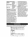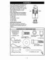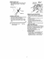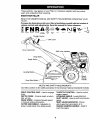
1
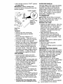
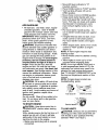
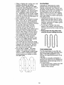
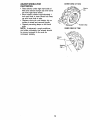
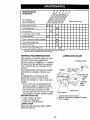
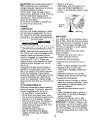
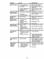
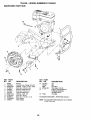
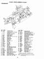
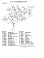
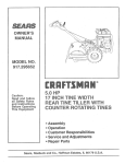
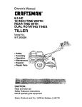
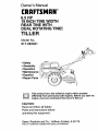
Owner's Manual [RI:IFTXMi:IN° 6.5 HP 19 INCH TINE WIDTH REAR TINE WITH DUAL ROTATING TINE... TILLER Model No. 917.293321 • Safety • Assembly • Operation • Maintenance • Espa_ol • Repair Parts differently from previously built engines. Before you start the This product has a low emission engine which operates engine, read and understand this Owner's Manual. CAUTION: Read and follow all Safety Rules and Instructions before operating this equipment. Sears, Roebuck and Co., Hoffman Estates, II 60179 Visit our Craftsman website:www.sears.com/craftsman Warranty ................................................2 Safety Rules ..........................................2 Product Specifications...........................4 Assembly ...............................................5 Operation ...............................................8 Maintenance ........................................14 Service and Adjustr".gnts.....................16 Storage ................................................20 Troubleshooting ..................................21 Illustrated Parts List .............................44 Parts Ordering ......................Back Cover LIMITEDTWO YEAR WARRANTYON CRAFTSMANTILLER For two (2) years from date of purchase, when this Craftsman Tiller is maintained, lubricated, and tuned up according to the operating and maintenance instructions in the owner's manual, Sears will repair free of charge any defect in material or workmanship. This Warranty does not cover: • Expendable items which become worn during normal use, such as tines, spark plugs, air cleaners and belts. • Repairs necessary because of operator abuse or negligence, including bent crankshafts and the failure to maintain the equipment according to the instructions contained in the owner's manual. • If this Craftsman Tiller is used for commercial or rental purposes, this Warranty applies for only thirty (30) days from the date of purchase. Warranty service is available by returning the Craftsman power mower to the nearest Sears service center/department in the United States. This warranty applies only while this product is in use in the United States. This Warranty gives you specific legal rights, and you may also have other rights which vary from state to state. SEARS, ROEBUCKAND CO., D/817WA, HOFFMAN ESTATES,IL 60179 IMPORTANT: This cutting machine is capable of amputating hands and feet and throwing objects. Failure to observe the following safety instructions could result in serious injury or death. TRAINING • Read the Owner's Manual carefully. Be thoroughly familiar with the controls and the proper use of the equipment. Know how to stop the unit and disengage the controls quickly. • Never allow children to operate the equipment. Never allow adults to operate the equipment without proper instruction. • Keep the area of operation clear of all persons, particularly small children, and pets. PREPARATION • Thoroughly inspect the area where the equipment is to be used and remove all foreign objects. 2 • Disengage all clutches and shift into neutral before starting the engine (motor). • Do not operate the equipment without wearing adequate outer garments. Wear footwear that will improve footing on slippery surfaces. • Handle fuel with care; it is highly flammable. • Use an approved fuel container. • Never add fuel to a running engine or hot engine. • Fill fuel tank outdoors with extreme care. Never fill fuel tank indoors. • Replace gasoline cap securely and clean up spilled fuel before restarting. • Use extension cords and receptacles as specified by the manufacturer for all units with electric drive motors or electric starting motors. • Never attempt to make any adjustments while the engine (motor) is running (except where specifically recommended by manufacturer). • Never operate the tiller without good visibility or light. • Be careful when tilling in hard ground. The tines may catch in the ground and propel the tiller forward. If this occurs, let go of the handlebars and do not restrain the machine. OPERATION • Do not put hands or feet near or under rotating parts. • Exercise extreme caution when operating on or crossing gravel drives, walks, or roads. Stay alert for hidden hazards or traffic. Do not carry passengers. • After striking a foreign object, stop the engine (motor), remove the wire from the spark plug, thoroughly inspect the tiller for any damage, and repair the damage before restarting and operating the tiller. • Exercise caution to avoid slipping or falling. • If the unit should start to vibrate abnormally, stop the engine (motor) and check immediately for the cause. Vibration is generally a warning of trouble. • Stop the engine (motor) when leaving the operating position. • Take all possible precautions when leaving the machine unattended. Disengage the tines, shift into neutral, and stop the engine. • Before cleaning, repairing, or inspecting, shut off the engine and make certain all moving parts have stopped. Disconnect the spark plug wire, and keep the wire away from the plug to prevent accidental starting. Disconnect the cord on electric motors. • Do not run the engine indoors; exhaust fumes are dangerous. • Never operate the tiller without proper guards, plates, or other safety protective devices in place. • Keep children and pets away. • Do not overload the machine capacity by attempting to till too deep at too fast a rate. • Never operate the machine at high speeds on slippery surfaces. Look behind and use care when backing. • Never allow bystanders near the unit. • Use only attachments and accessories approved by the manufacturer of the tiller. MAINTENANCE • AND STORAGE Keep machine, attachments, and accessories in safe working condition. • Check shear pins, engine mounting bolts, and other bolts at frequent intervals for proper tightness to be sure the equipment is in safe working condition. • Never store the machine with fuel in the fuel tank inside a building where ignition sources are present, such as hot water and space heaters, clothes dryers, and the like. Allow the engine to cool before storing in any enclosure. • Always refer to the operator's guide instructions for important details if the tiller is to be stored for an extended period. _,Look for this symbol to point out important safety precautions. It means CAUTIONN! BECOMEAWARE!!! YOUR SAFETY IS INVOLVED. _CAUTION: Always disconnect spark plug wire and place wire where it cannot contact spark plug in order to prevent accidental starting when setting up, transporting, adjusting or making repairs. _,WARNING: The engine exhuast from this product contains chemicals known to the State of California to cause cancer, birth defects or other reproductive harm. 3 PRODUCT SPECIFICATIONS CUSTOMER GASOLINE CAPACITY: 3 QUARTS UNLEADED REGULAR OIL (API-SF/SG/SH): CAPACITY: 19 OZ.) SAE 30 (ABOVE 40°F) SAE5W-30/10W-30 (BELOW 40°F) CHAMPION RJ19LM OR J19LM SPARK PLUG : (GAP: .030") RESPONSIBILITIES • Read and observe the safety rules. • Follow a regular schedule in maintaining, caring for and using your tiller. • Follow the instructions under the "Maintenance" and "Storage" sections of this Owner's Manual. ,_WARNING: This unit is equipped with an internal combustion engine and should not be used on or near any unimproved forest-covered, brushcovered or grass covered land unless the engine's exhaust system is equipped with a spark arrester meeting applicable local or state laws (if any). If a spark arrester is used, it should be maintained in effective working order by the operator. In the state of California the above is required by law (Section 4442 of the California Public Resources Code). Other states may have similar laws. Federal laws apply on federal lands. See your Sears Authorized Service Center for spark arrester. Refer to the Repair Parts section of this manual for part number. Congratulations on your purchase of a Craftsman Tiller. It has been designed, engineered and manufactured to give you the best possible dependability and performance. Should you experience any problems you cannot easily remedy, please contact your nearest authorized Sears Service Center/Department. We have competent, well-trained technicians and the proper tools to service or repair this unit. Please read and retain this manual. The instructions will enable you to assemble and maintain your tiller properly. Always observe the "SAFETY RULES". Your new tiller has been assembled at the factory with exception of those parts left unassembled for shipping purposes. To ensure safe and proper operation of your tiller all parts and hardware you assemble must be tightened securely. Use the correct tools as necessary to insure proper tightness. These accessories were available when the tiller was purchased. They are also available at most Sears Retail outlets and Service Centers. Most Sears Stores can order repair parts for you when you provide the model number of your tiller. ENGINE AIR,FILTER TILLER ENGINE__OIL [ STABILIZER PERFORMANCE FURROW TILLER I _ OPENER MAINTENANCE BELT TINES SHEAR 4 PIN HAIRPIN CLIP Your new tiller has been assembled at the factory with exception of those parts left unassembled for shipping purposes. To ensure safe and proper operation of your tiller all parts and hardware you assemble must be tightened securely. Use the correct tools as necessary to insure proper tightness. TOOLS REQUIRED FRONT RIGHT LEFT FOR ASSEMBLY A socket wrench set will make assembly easier. Standard wrench sizes are listed. (1) Utility knife (1) Wire cutter (1) Tire pressure gauge (1) Screwdriver (1) Pair of pliers (1) 9/16" wrench OPERATOR'S POSITION OPERATOR'S POSITION When right or left hand is mentioned in this manual, it means when you are in the operating position (standing behind tiller handles). CONTENTS OF HARDWARE PACK @ /llllll/Y (2) Handle Locks (1) Carriage 3/8-16 UNC (1) Hairpin Bolt x 1 Gr. 5 (1) Center Locknut 3/8-16 UNC (1)Cable Clip Clips (1) Pivot Bolt 3/8-16 UNC Grade ol (1) Flat Washer 13/32 x 1 x 11 Ga. Q (1) Handle Lock Lever (2) Shear Pins & Clips 5 5 UNPACKING CARTON _iI,CAUTION: Be careful of exposed staples when handling or disposing of cartoning material. IMPORTANT:When unpacking and assembling tiller, be careful not to stretch or kink cables. • While holding handle assembly, cut cable ties securing handle assembly to top frame. Let handle assembly rest on tiller. • Remove top frame of carton. • Slowly ease handle assembly up and place on top of carton. • Cut down right hand front and right hand rear corners of carton, lay side carton wall down. • Remove packing material from handle assembly. • Separate shift rod from handle assembly. Loosen Handle Lever to Move • Insert pivot bolt in front part of plate and tighten. • Cut down remaining corners of carton and lay panels flat. • Lower the handle assembly. Tighten nut on carriage bolt so handle moves with some resistance. This will allow for easier adjustment. • Place flat washer on threaded end of handle lock lever. Shift Rod • Insert handle lock lever through handle base and gearcase. Screw in handle lock lever just enough to hold lever in place. • Insert second handle lock (with teeth inward) in the slot of the handle base (just inside of washer). • Raise handle assembly to highest position and securely tighten handle lock lever by rotating clockwise. Leaving handle assembly in highest position will make it easier to connect shift rod. Assembly INSTALL HANDLE • Insert one handle lock (with teeth facing outward) in gearcase notch. (Apply grease on smooth side of handle lock to aid in keeping lock in place until handle assembly is lowered into position.) VIEWED FROM R.H. SIDE OF TILLER __Ge Flat Washer Handle Slot Rear Cartridge arcase Notch ,_ Lever Gearcase_ andle Assembly _,_ Handle Lock /Ha_nd,eLock Locknut_ "%'%" Handle Base • Grasp handle assembly. Hold in "up" position. Be sure handle lock remains in gearcase notch. Slide handle assembly into position. • Rotate handle assembly down. Insert rear carriage bolt first, with head of bolt on L.H. side of tiller and loosely assemble Iocknut. 6 Pivot Bolt INSERT CABLE CLIP • Insert plastic cable clip into hole on the back of handle column. Push cables into clip, Hairpin lip Shift Lever Indicator Shift Handle Column Cable Clip REMOVE TILLER FROM CRATE • Adjust handle assemby to lowest position. Be sure lock lever is tightened securely. • Make sure shift lever indicator is in "N" (neutral) position. • Tilt tiller forward by lifting handle. Separate cardboard cover from leveling shield. • Rotate tiller handle to the right and pull tiller out of carton. CHECK TIRE PRESSURE The tires on your unit were overinflated at the factory for shipping purposes. Correct and equal tire pressure is important for best tilling performance. • Reduce tire pressure to 20 PSI. HANDLE HEIGHT • Handle height may be adjusted to better suit operator. (See "TO ADJUST HANDLE HEIGHT" in the Service and Adjustments section of this manual). CONNECT SHIFT ROD • Insert end of shift rod farthest from bend into hole of shift lever indicator. • Insert hairpin clip through hole of shift rod to secure with bend of clip on right side. _L"-- Attach this End To shift \ Shift Rod Lever Indicator 7 These symbols may appear on your Tiller or in literature Learn and understand their meaning. supplied with the product. KNOW YOUR TILLER READ THIS OWNER'S TILLER. MANUALAND SAFETY RULES BEFORE OPERATING YOUR Compare the illustrations with your tiller to familiarize yourself with the location of various controls and adjustments. Save this manual for future reference, TILLING FORWARD NEUTRAL REVERS_ CAUTION OR Throttle WARNING ENGINE ON ENGINE FAST SLOW CHOKE FUEL OIL STOp O OFF Control Lever Drive Control Bar Shift Lever Indicator Drag Depth Leveling Shield Recoil Starter Handle MEETS ANSI SAFETY REQUIREMENTS Our tillers conform to the safety standards of the American National Standards Institute. THROTTLE CONTROL - Used to control engine speed. LEVELING SHIELD - Levels tilled soil. SHIFT LEVER - Used to shift transmission gears. SHIFT LEVER INDICATOR - Shows which gear the transmission is in. RECOIL STARTER HANDLE - Used to start the engine. DRIVE CONTROL BAR - Used to engage tines. DEPTH STAKE - Controls depth at which tiller will dig. DRAG STAKE - Controls forward speed in forward rotating till position. OUTER SIDE SHIELD - Adjustable to protect small plants from being buried. 8 The operation of any tiller can result in foreign objects thrown into the eyes, which can result in severe eye damage. Always wear safety glasses or eye shields before starting your tiller and while tilling. We recommend a wide vision safety mask over spectacles or standard safety glasses. HARD TO SHIFT GEARS HOW TO USE YOUR TILLER Know how to operate all controls before adding fuel and oil or attempting to start engine. STOPPING TINES AND DRIVE • Release drive control bar to stop movement. • Move shift lever to "N" (neutral) position. ENGINE • Briefly engage drive control bar and release or rock tiller forward and backward until are able to shift gears. DEPTH STAKE The depth stake can be raised or lowered to allow you more versatile tilling and cultivating, or to more easily transport your tiller. Shallowest Tilling • Move throttle control to "STOP" position. If equipped with stop switch, move switch to "STOP" position. • Never use choke to stop engine. Drive Control Bar ;ition Transport Position Deepest Tilling Depth Stake Shift Lever J DRAG STAKE The drag stake should be raised when tilling the counter rotating (_) till position. The drag stake should be lowered when tilling in the forward rotating (:_) till position. Drive Control Bar "DISENGAGED" Position TINE OPERATION - WITH WHEEL DRIVE • Always release drive control bar before moving shift lever into another position. • Tine movement is achieved by moving shift lever to either the counter rotating (_) till position or the forward rotating (;_) till position and engaging drive control bar. FORWARD - WHEELS ONLY/TINES STOPPED • Release drive control bar and move shift lever indicator to "F" (forward) position. Engage drive control bar and tiller will move forward. REVERSE - WHEELS ONLY/TINES STOPPED • DO NOT STAND DIRECTLY BEHIND TILLER. • Release the drive control bar. • Move throttle control to "SLOW" position. • Move shift lever indicator to "R" (reverse) position. • Hold drive control bar against the handle to start tiller movement. Lowered/ (Forward Rotating till) Raised (Counter rotatingtill) TILLING • Use the counter rotating tine drive when tilling hard or rockey soil, virgin ground or sod. • Release depth stake and drag stake pins. Pull the depth stake up for increased tilling depth. Raise the drag stake. Place proper pin in hole of depth stake or drag stake to lock in position. • Place shift lever indicator in counter rotating (_) till position. • Hold the drive control bar against the handle to start tilling movement. Tines and wheels will both turn. 9 • Move throttle control to "FAST" position for deep tilling. IMPORTANT: Always release drive control bar before moving shift lever into another position. "Locked" Position OUTER SIDE SHIELDS The back edges of the outer side shields are slotted so that the shields can be raised for deep tilling and lowered for shallow tilling to protect small plants from being buried. Loosen nut "A" in slot and nut "B". Move shield to desired position (both sides). Retighten nuts. TO TRANSPORT ,_CAUTION: Before lifting or transporting, allow tiller engine and muffler to cool. Disconnect spark plug wire. Drain gasoline from fuel tank. AROUND THE YARD Nu, Pos,,,o' Outer Side Shield TURNING • Release the drive control bar. • Move throttle control to "SLOW" position. • Place shift lever indicator in "F" (forward) position. Tines will not turn. • Lift handle to raise tines out of ground. • Swing the handle in the opposite direction you wish to turn, being careful to keep feet and legs away from tines. • When you have completed your turnaround, release the drive control bar and lower handle. Place shift lever in till position and move throttle control to desired speed. To begin tilling, hold drive control bar against the handle. CULTIVATING • Use the forward rotating tine drive when cultivating, tilling soft ground or tilling pre-tilled soil. • Release the depth and drag stake pins. Lower drag stake. Pull the depth stake up for increased tilling depth. Place proper pin in hole of depth stake or drag stake to lock in position. • Place shift lever indicator in forward to • Release the depth stake pin. Move the depth stake down to the top hole for transporting the tiller. Place depth stake pin in hole of depth stake to lock in position. This prevents tines from scuffing the ground. • Place shift lever indicator in "F" (forward) position for transporting. • Hold the drive control bar against the handle to start tiller movement. Tines will not turn. • Move throttle control to desired speed. AROUND TOWN • Disconnect spark plug wire. • Drain fuel tank. • Transport in upright position to prevent oil leakage. BEFORE STARTING ENGINE IMPORTANT: Be very careful not to allow dirt to enter the engine when checking or adding oil or fuel. Use clean oil and fuel and store in approved, clean, covered containers, use clean fill funnels. CHECK ENGINE OIL LEVEL • The engine in your unit has been shipped, from the factory, already filled with SAE 30 summer weight oil. • With engine level, clean area around oil filler plug and remove plug. • Engine oil should be to point of overlowing when engine is level. For rotating (_) till position. approximate capacity see "PRODUCT • Hold the drive control bar against the SPECIFICATIONS" on page 4 of this handle to start tilling movement. Tines manual. All oil must meet A.P.I. Service and wheels will both turn. Classification SF, SG or SH. • Move throttle control "FAST" position for • Reinstall engine oil cap and tighten deep tilling. To cultivate, throttle control • For cold weather operation you should can be set at any desired speed, dechange oil for easier starting (See oil pending on how fast or slow you wish viscosity chart in the Maintenance to cultivate. section of this manual). • Always lower the drag stake when • To change engine oil, see the Mainte° using the forward rotating tine drive. 10 nance section in this manual. Oil Fill ADD GASOLINE • Fill fuel tank. Use fresh, clean, regular unleaded gasoline. (Use of leaded gasoline will increase carbon and lead oxide deposits and reduce valve life. IMPORTANT: When operating in temperatures below 32°F (0°C), use fresh, clean, winter grade gasoline to help insure good cold weather starting. _I, WARNING: Experience indicates that alcohol blended fuels (called gasohol or using ethanol or methanol) can attract moisture which leads to separation and formation of acids during storage. Acidic gas can damage the fuel system of an engine while in storage. To avoid engine problems, the fuel system should be emptied before storage of 30 days or longer. Drain the gas tank, start the engine and let it run until the fuel lines and carburetor are empty. Use fresh fuel next season. See Storage section of this manual for additional information. Never use engine or carburetor cleaner products in the fuel tank or permanent damage may occur. _:_CAUTION: Fill to within 1/2 inch of top of fuel tank to prevent spills and to allow for fuel expansion, tf gasoline is accidentally spilled, move machine away from area of spill. Avoid creating any source of ignition until gasoline vapors have disappeared. Do not overfill. Wipe off any spilled oil or fuel. Do not store, spill or use gasoline near an open flame. • Move shift lever indicator to "N" (neutral) position. • Place throttle control in "FAST" position. • Turn fuel shut-off valve 1/4 turn to OPEN position. • Move choke control to CHOKE position. • Grasp recoil starter handle with one hand and grasp tiller handle with other hand. Pull rope out slowly until engine reaches start of compression cycle (rope will pull slightly harder at this point). • Pull recoil starter handle quickly. Do not let starter handle snap back against starter. • If engine fires but does not start, move choke control to half choke position. Pull recoil starter handle until engine starts. • When engine starts, slowly move choke control to "RUN" position as engine warms up. NOTE: A warm engine requires less choking to start. • Move throttle control to desired running position. • Allow engine to warm up for a few minutes before engaging tines. NOTE: If at a high altitude (3000 feet) or in cold temperatures (below 40°F), the carburetor fuel mixture may need to be adjusted for best engine perfomrance. See "TO ADJUST CARBURETOR" in the Service and Adjustments section of this manual. NOTE: If engine does not start, see troubleshooting points. Fuel shut-off TO START ENGINE Choke controls Rewind starter _._ _CAUTION: Keep drive control bar in "DISENGAGED" position when starting engine. When starting engine for the first time or if engine has run out of fuel, it will take extra pulls of the recoil starter to move fuel from the tank to the engine. • Make sure spark plug wire is properly connected. TILLING HINTS h_CAUTION: Until you are accustomed to andling your tiller, start actual field use with throttle in slow position (mid-way between "FAST" and "IDLE"). 11 • Tilling is digging into, turning over, and breaking up packed soil before planting. Loose, unpacked soil helps root growth. Best tilling depth is 4" to 6". A tiller will also clear the soil of unwanted vegetation. The decomposition of this vegetable matter enriches the soil. Depending on the climate (rainfall and wind), it may be advisable to till the soil at the end of the growing season to further condition the soil. • Soil conditions are important for proper tilling. Tines will not readily penetrate dry, hard soil which may contribute to excessive bounce and difficult handling of your tiller. Hard soil should be moistened before tilling; however, extremely wet soil will "ball-up" or clump during tilling. Wait until the soil is less wet in order to achieve the best results. When tilling in the fall, remove vines and long grass to prevent them from wrapping around the tine shaft and slowing your tilling operation. • You will find tilling much easier if you leave a row untilled between passes. Then go back between tilled rows.There are two reasons for doing this. First, wide turns are much easier to negotiate than about-faces. Second, the tiller won't be pulling itself, and you, toward the row next to it. • Do not lean on handle. This takes weight off the wheels and reduces traction. To get through a really tough section of sod or hard ground, apply upward pressure on handle or lower the depth stake. CULTIVATING Cultivating is destroying the weeds between rows to prevent them from robbing nourishment and moisture from the plants. At the same time, breaking up the upper layer of soil crust will help retain moisture in the soil. Best digging depth is 1" to 3" (2.5-7.5 cm). Lower the outer side shields to protect small plants from being buried. • Cultivate up and down the rows at a speed which will allow tines to uproot weeds and leave the ground in rough condition, promoting no further growth of weeds and grass. • Do not lean on handle, this takes weight off the wheels, reduces traction, and may cause the tiller to skip over the ground. • Always lower the drag stake when using the forward rotating tine drive. L f- TINE SHEAR PINS The tine assemblies on your tiller are secured to the tine shaft with shear pins (See 'q'INE REPLACEMENT" in the Service and Adjustments section of this manual). If the tiller is unusually overloaded or jammed, the shear pins are designed to break before internal damage occurs to the transmission. • If shear pin(s) break, replace only with those shown in the Repair Parts section of this manual. !, ; 5 J 12 ADJUST WHEELS FOR CULTIVATING OUTER VIEW OF TIRE Clevis • Place blocks under right hand side of tiller and remove hairpin clip and clevis pin from right hand wheel. • Move wheel outward approximately 1 inch until hole in inner wheel hub lines up with inner hole in axle. • Replace clevis pin and hairpin clip on inside of wheel and remove blocks. • Repeat preceding steps on left hand side. NOTE: In extremely rough conditions and while cultivating, the wheels should be moved outward on the axle for increased stability. Pin Hairpin Cllip INNER VIEW OF TIRE Clevis Pin Hairpir 13 MAINTENANCE SCHEDULE FILL IN DATES AS YOU COMPLETE REGULAR SERVICE Check Engine Change SERVICE Oil Level Ikf I_ Engine Oil _1,_. Oil Pivot Points I1_ Inspect Spark Arrester / Muffler Inspect Air Screen Clean or Replace Clean Engine Replace Spark DATES Air Cleaner Cylinder v' Cartridge Fins v' Plug RH Gear Case Grease Fitting (loz,) 1 - Change more often when operatingundera heavy loador in highambienttemperatures, 2 - Servicemore often when operatingin dirtyor dustyconditions, GENERAL RECOMMENDATIONS LUBRICATION The warranty on this tiller does not cover items that have been subjected to operator abuse or negligence. To receive full value from the warranty, the operator must maintain tiller as instructed in this manual. Some adjustments will need to be made periodically to properly maintain your tiller. All adjustments in the Service and Adjustments section of this manual should be checked at least once each season. • Once a year you should replace the spark plug, clean or replace air filter, and check tines and belts for wear. A new spark plug and clean air filter assure proper air-fuel mixture and help your engine run better and last longer. BEFORE EACH USE * Throttle Control ** Engine / ***RH Gear Case Grease Fitting Drag Stake Pin / _-_* Depth /Stake Pin _* Leveling Shield ', Hinges I Wheel Hub * Idler Bracket SAE 30 OR 5W-30 Motor Oil ** Refer to Maintenance "ENGINE" *** EP #1 Grease • Check engine oil level. • Check tine operation. • Check for loose fasteners. LUBRICATION Keep unit well lubricated CATION CHART"). CHART (See "LUBRI- 14 Section ACAUTION: Disconnect spark plug wire before performing any maintenance (except carburetor adjustment) to prevent accidental starting of engine. Prevent fires! Keep the engine free of grass, leaves, spilled oil, or fuel. Remove fuel from tank before tipping unit for maintenance. Clean muffler area of all grass, dirt, and debris. Do not touch hot muffler or cylinder fins as contact may cause burns. • Remove oil fill plug. • Refill engine with oil through oil fill tube. See "CHECK ENGINE OIL LEVEL" in the Operation section of this manual. ENGINE Oil drain LUBRICATION Plug_ Use only high quality detergent oil rated with API service classification SF, SG or SH. Select the oil's SAE viscosity grade according to your expected temperature. SAE VISCOSITY GRADES 30 _ 20 _ TEMPERATURE .10 _ 40 _ 4_ RANGE ANTICIPATED 60 c 10 _ BEFORE 80 _ 20 _ 30 ° NEXT OIL CHANGE NOTE: Although multi-viscosity oils (5W30, 10W-30, etc.) improve starting in cold weather, these multi-viscosity oils will result in increased oil consumption when used above 40°F (4°C). Check your engine oil level more frequently to avoid possible engine damage from running low on oil. Change the oil after every 50 hours of operation or at least once a year if the tiller is not used for 50 hours in one year. Check the crankcase oil level before starting the engine and after each five (5) hours of continuous use. Add SAE 30 motor oil or equivalent. Tighten oil filler plug securely each time you check the oil level. TO CHANGE ENGINE OIL Determine temperature range expected before oil change. All oil must meet API service classification SF, SG or SH. • Be sure tiller is on level surface. • Oil will drain more freely when warm. • Use a funnel to prevent oil spill on tiller, and catch oil in a suitable container. • Remove oil drain plug. Be careful not to allow dirt to enter the engine. For easier removal of plug use 7/16 12 Pt. socket with extension. • Tip tiller forward to drain oil. • After oil has drained completely, replace oil drain plug and tighten securely. _ • (:_ : _'_ D'_-i Oil Fill Plug AIR FILTER Your engine will not run properly using a dirty air filter. Clean the foam pre-cleaner after every 50 hours of operation or every season. Service paper cartridge every 100 hours of operation or every season, whichever occurs first. Service air cleaner more often under dusty conditions. • Remove knob and cover. Lift air cleaner assembly off stud. TO SERVICE PRE-CLEANER • Remove foam pre-cleaner from air filter. • Wash it in liquid detergent and water. • Squeeze it dry in a clean cloth. • If very dirty or damaged, replace precleaner. • Reinstall pre-cleaner onto air filter. • Reinstall cover and secure with knob. TO SERVICE CARTRIDGE • Carefully remove cartridge to prevent debris from entering carburetor. Clean base carefully to prevent debris from entering carburetor. • Remove foam pre-cleaner from air filter. • Clean cartridge by tapping gently on flat surface. If very dirty or damaged, replace cartridge. • Reinstall pre-cleaner onto air filter. • Reinstall cover and secure with knob. IMPORTANT: Petroleum solvents, such as kerosene, are not to be used to clean the cartridge. They may cause deterioration of the cartridge. Do not oil cartridge. Do not use pressurized air to clean or dry cartridge. 15 MUFFLER _Cover Knob Cover_ _ Cartridge Precleaner _ SPARK PLUG Stu6 _ Base _ COOLING Do not operate tiller without muffler. Do not tamper with exhaust system. Damaged mufflers or spark arresters could create a fire hazard. Inspect periodically and replace if necessary. If your engine is equipped with a spark arrester screen assembly, remove every 50 hours for cleaning and inspection. Replace if damaged. SYSTEM Your engine is air cooled. For proper engine performance and long life keep your engine clean. • Clean air screen frequently using a stiff-bristled brush. • Keep cylinder fins, levers, and linkage free of dirt and chaff. Blower Screen Muffler Replace spark plugs at the beginning of each tilling season or after every 50 hours of use, whichever comes first. Spark plug type and gap setting is shown in "PRODUCT SPECIFICATIONS" on page 4 of this manual. TRANSMISSION Once a season, lubricate the right hand gear case grease fitting with 1 oz. of EP #1 grease. CLEANING • Clean engine, wheels, finish, etc. of all foreign matter. • Keep finished surfaces and wheels free of all gasoline, oil, etc. • Protect painted surfaces with automotive type wax. We do not recommend using a garden hose to clean your unit unless the muffler, air filter and carburetor are covered to keep water out. Water in engine can result in a shortened engine life. A_.CAUTION: Disconnect spark plug wire from spark plug and place wire where it cannot come into contact with plug. ÷ .., _ TILLER TO ADJUST HANDLE i _Handle _ HEIGHT Select handle height best suited for your tilling conditions. Handle height will be different when tiller digs into soil. • First loosen handle lock lever.(Do not loosen too much or handle locks may fall out.) • Handle can be positioned at different settings between "HIGH" and "LOW" positions. • Retighten handle lock lever securely after adjusting. (Low) Position 16 !i, (High) Position Handle Lock Lever TIRE CARE Belt Guard _CAUTION: When mounting tires, unless beads are seated, overinflation can cause an explosion. • Maintain 20 pounds of tire pressure. If tire pressures are not equal, tiller will pull to one side. • Keep tires free of gasoline or oil which can damage rubber. TO REMOVE WHEEL • Place blocks under transmission to keep tiller from tipping. • Remove hairpin clip and clevis pin from wheel. • Remove wheel and tire. • Repair tire and reassemble. Clevis Pin Nut and Washer (Located Behind Tire) Screws Hairpin Clip and Clevis Pin TO REPLACE BELT GROUND DRIVE • Remove belt guard as described in "TO REMOVE BELT GUARD". • Remove old belt by slipping off engine pulley first then remove from transmission pulley. • Place new belt in groove of transmission pulley and into engine pulley. BELT MUST BE IN GROOVE ON TOP OF IDLER PULLEY. NOTE POSITION OF BELT TO GUIDES. • Check belt adjustment as described below. • Replace belt guard. • Reposition wheel and replace clevis pin and hairpin clip. GROUND DRIVE BELT ADJUSTMENT Hairpin Clip For proper belt tension, the extension spring should have about 5/8 inch stretch when drive control bar is in "ENGAGED" position. This tension can be attained as follows: TO REMOVE BELT GUARD NOTE: For ease of removal, remove hairpin clip and clevis pin from left wheel. Pull wheel out from tiller about 1 inch. • Remove two (2) screws, one (1) nut and washer from side of belt guard. • Pull belt guard out and away from unit. • Replace belt guard by reversing above procedure. • Loosen cable clip screw securing the drive control cable. • Slide cable forward for less tension and rearward for more tension until about 5/8 inch stretch is obtained while the drive control bar is engaged. • Tighten cable clip screw securely. Belt Guide "B" Engine Pulley., ip Screw Control Cable Tension Idler Pulley _- Extension Spring" Transmission Pulley 17 TINE REPLACEMENT To maintain the superb tilling performance of this machine the tines should be checked for sharpness, wear, and bending, particularly the tines which are next to the transmission. If the gap between the tines exceeds 3-1/2 inches they should be replaced or straightened as necessary. For tines that are slightly worn, the bolted tine and hub assemblies caEbe switched between sides to continue tilling in the same tilling mode if tilling in a different mode is desired then the bolted tine and hub assemblies should be switched back to their original side so that the tine edge with the least wear will be used. _,CAUTION: Tines are sharp. Wear gloves or other protection when handling tines. A badly worn tine causes your tiller to work harder and dig more shallow. Most important, worn tines cannot chop and shred organic matter as effectively nor bury it as deeply as good tines. A tine this worn needs to be replaced. New Tine Worn Tine / Trans_ ssion / I I I I I I _ Sharp Edges Sharp Ed Sharp Edges Hairpin Clip / 18 3-1/2" MAX ENGINE TO ADJUST CARBURETOR Maintenance, repair, or replacement of the emission control devices and systems, which are being done at the customers expense, may be performed by any non-road engine repair establishment or individual. Warranty repairs must be performed by an authorized engine manufacturer's service outlet. TO ADJUST THROTTLE CONTROL CABLE The carburetor has been preset at the factory and adjustment should not be necessary. However, engine performance can be affected by differences in fuel, temperature, altitude or load. If the carburetor does need adjustment, contact your nearest authorized service center/ department. High speed stop is factory adjusted. Do not adjust or damage may result. IMPORTANT: Never tamper with the engine governor, which is factory set for proper engine speed. Overspeeding the engine above the factory high speed setting can be dangerous. If you think the engine-governed high speed needs adjusting, contact your nearest authorized service center/department, which has the proper equipment and experience to make any necessary adjustments. The throttle control has been preset at the factory and adjustment should not be necessary. If adjustment is necessary, proceed as follows: • With engine not running, move remote throttle control lever to "FAST" position. • If throttle lever on engine touches high speed stop, no further adjustment is necessary. If throttle lever does not touch high speed stop, continue with adjustment procedure. • Loosen cable clamp screw. • Move throttle lever up until it touches high speed stop, and hold in this position. • Tighten cable clamp screw securely. F uel Tank / Clamp Screw _ I/ and Wire Governor Control Lever 19 Immediately prepare your tiller for storage at the end of the season or if the unit will not be used for 30 days or more. _i, CAUTION" Never store the tiller with gasoline in the tank inside a building where fumes may reach an open flame or spark. Allow the engine to cool before storing in any enclosure. TILLER • Clean entire tiller (See "CLEANING" in the Maintenance section of this manual). • Inspect and replace belts, if necessary (See belt replacement instructions in the Service and Adjustments section of this manual). • Lubricate as shown in the Maintenance section of this manual. • Be sure that all nuts, bolts and screws are securely fastened. Inspect moving parts for damage, breakage and wear. Replace if necessary. • Touch up all rusted or chipped paint surfaces; sand lightly before painting. NOTE: Fuel stabilizer is an acceptable alternative in minimizing the formation of fuel gum deposits during storage. Add stabilizer to gasoline in fuel tank or storage container. Always follow the mix ratio found on stabilizer container. Run engine at least 10 minutes after adding stabilizer to allow the stabilizer to reach the carburetor. Do not drain the gas tank and carburetor if using fuel stabilizer. ENGINEOIL Drain oil (with engine warm) and replace with clean oil. (See "ENGINE" in the Maintenance section of this manual). CYLINDER(S) • Remove spark plug. • Pour 1 ounce (29 ml) of oil through spark plug hole into cylinder, • Pull starter handle slowly several times to distribute oil. • Replace with new spark plug. OTHER • Do not store gasoline from one season to another. • Replace your gasoline can if your can starts to rust. Rust and/or dirt in your gasoline will cause problems. • If possible, store your unit indoors and cover it to give protection from dust and dirt. • Cover your unit with a suitable protective cover that does not retain moisture. Do not use plastic. Plastic cannot breathe which allows condensation to form and will cause your unit to rust. IMPORTANT: Never cover tiller while engine and exhaust areas are still warm. ENGINE FUELSYSTEM IMPORTANT: It is important to prevent gum deposits from forming in essential fuel system parts such as the carburetor, fuel filter, fuel hose, or tank during storage, also, experience indicates that alcohol blended fuels (called gasohol or using ethanol or methanol) can attract moisture which leads to separation and formation of acids during storage. Acidic gas can damage the fuel system of an engine while in storage. • Drain the fuel tank. • Start the engine and let it run until the fuel lines and carburetor are empty. • Never use engine or carburetor cleaner products in the fuel tank or permanent damage may occur. • Use fresh fuel next season. 20 PROBLEM Will not start CAUSE CORRECTION 1. Out of fuel. 2. Engine not "CHOKED" properly. 3. Engine flooded. 4. Dirty air cleaner. 5. Water in fuel. 6. Clogged fuel tank. 7. Loose spark plug wire. 8. Bad spark plug or improper gap. 9. Carburetor out of adjustment. Hard to start 1.Throttle control not set properly. 2. Dirty air cleaner. 3. Bad spark plug or improper gap. 4. Stale or dirty fuel. 5. Loose spark plug wire. 6. Carburetor out of. adjustment. Loss of power 1. Engine is overloaded. 2. Dirty air cleaner. 3. Low oil level/dirty oil. 4. Faulty spark plug. 5. Oil in fuel. 6. Stale or dirty fuel. 7. Water in fuel. 8. Clogged fuel tank. 9. Spark plug wire loose. 10. Dirty engine air screen. 11. Dirty/clogged muffler. 12. Carburetor out of adjustment. 13. Poor compression. 21 1. Fill fuel tank. 2. See "TO START ENGINE" in the Operation section. 3. Wait several minutes before attempting to start. 4. Clean or replace air cleaner cartridge. 5. Drain fuel tank and carbure tor, and refill tank with fresh gasoline. 6. Remove fuel tank and clean. 7. Make sure spark plug wire is seat ed properly on plug. 8. Replace spark plug or adjust gap. 9. Make necessary adjustments. 1. Place throttle control in "FAST" position. 2. Clean or replace air cleaner cartridge. 3. Replace spark plug or adjust gap. 4. Drain fuel tank and refill with fresh gasoline. 5. Make sure spark plug wire is seated properly on plug. 6. Make necessary adjustments. 1. Set depth stake for shallower tilling. 2. Clean or replace air cleaner cartridge. 3. Check oil level/change oil. 4. Clean and regap or change spark plug. 5. Drain and clean fuel tank and refill, and clean carburetor. 6. Drain fuel tank and refill with fresh gasoline. 7. Drain fuel tank and carbure tor, and refill tank with fresh gasoline. 8. Remove fuel tank and clean. 9. Connect and tighten spark plug wire. 10. Clean engine air screen. 11. Clean/replace muffler. 12. Make necessary adjustments. 13. Contact an authorized Sears Service Center/Department. PROBLEM CAUSE CORRECTION Engine overheats 1. Low oil level/dirty oil. 2. Dirty engine air screen. 3. Dirty engine. 4. Partially plugged muffler. 5. Improper carburetor adjustment. Excessive bounce/ difficult handling 1. Ground too dry and hard. 2. Depth stake incorrectly adjusted• 1. Check oil level/change oil. 2. Clean engine air screen. 3. Clean cylinder fins, air screen, muffler area. 4. Remove and clean muffler. 5. Adjust carburetor to richer position• 1. Moisten ground or wait for more favorable soil conditions. 2. Adjust depth stake. Soil balls up or clumps 1. Ground too wet. 1. Wait for more favorable conditions. Engine runs but tiller won't move 1. Tine control is not engaged. 2. V-belt not correctly adjusted. 3. V-belt is off pulley(s). 1. Engage tine control. Engine runs but labors when tilling Tines skip over ground 1. Tilling too deep. tilling. 2. Throttle control not properlyadjusted. 3. Carburetor out of adjustment. 1. Drag Stake not lowered in forward rotating till mode. 2. Improper tilling mode. Hard to shift into gear 1. Gears not timed. Tiller shuts off when drive control bar engaged 1. Shift lever set in between counter rotating till position and forward rotating till position. 2. Tines jammed 2. Inspect/adjust V-belt. 3. Inspect V-belt. 1. Set depth stake for shallower 2. Check throttle control setting• 3. Make necessary adjustments. 1. Lower Drag Stake . o 22 soil Forward rotating tine drive should only be used for soft ground or for soil that has already been tilled. Briefly engage drive control bar and release or rock tiller forward and backward until are able to shift gears. • Shift to either counter rotating till position or forward rotating till position. 2. Clear tines. TILLER -- MODEL NUMBER 917.293321 HANDLES 7 9 \ 2 ',_, % 15 11 \ \ 31 \\ KEY NO. 1 2 3 4 5 6 7 8 9 10 11 12 13 14 15 16 17 18 PART NO. 164743 141406 110673X 127254X 6712J 137119 110641X 71191008 72010520 110646X STD624003 81328 138295 109313X 110702X STD533710 109229X STD541437 KEY NO. DESCRIPTION Throttle, Control Grip, Handle Grommet, Handle Bar, Drive Control Assembly Cap, Vinyl Panel, Control Bushing, Split *Screw, Pan Head #10-24 *Bolt, 5/16-18 x 2-1/2 Handle, Grip *Clip, Hairpin Bolt, Shoulder Handle, Shift Grommet, Rubber Rod, Shift *Bolt, RBHD SQNI< 3/8-16 x 1 Gr 5 Lock, Handle *Nut, Crownlock 3/8-16 PART NO. 19 20 21 22 23 19131611 109228X 150629 165197 86777 24 25 26 27 29 30 31 9484R 73970500 110675X 73900400 STD541462 7192J 150696 DESCRIPTION Washer 13/32 x 1 x 11 Ga, Lever, Lock, Handle Handle, Assemble Clip, Plastic, Cable Screw, Hex, Washer Hd, Slotted #10-24 x 1/2 Qip Locknut, Hex, Flange Clutch, Cable *Nut, Hex Flange 1/4-20 UNC *Nut, Keps #10-24 Tie,Cable Bolt, Pivot *STANDARDHARDWARE--PURCHASELOCALLY NOTE: All component dimensions nches. 1 inch = 25.4 mm 44 given in U.S. TILLER -- MODEL NUMBER 917.293321 MAINFRAME, LEFT SIDE 3 1\ 37 36 16 35 31 19 46 3O 28 23 4O 24 25_ KEY NO. PART NO. 1 2 3 4 5 6 7 8 9 STD541031 STD551137 STD541037 170127 164329 162756X505 STD532505 161530 86777 10 11 12 13 14 15 16 19 21 22 23 9484R STD551125 STD541025 23230506 110652X STD551031 145102 12000028 156117 74770508 102190X 150750 795R 126875X 24 KEY NO. DESCRIPTION *Nut, Hex 5/16-18 *Washer, Lock 3/8 "Nut, Hex 3/8-16 Shield, Inner Belt Guard Pin, Shift Lever Lever, Shift *Bolt, Carriage 1/4-20 x 1/2 Gr. 5 Plate, Shift indicator Screw, Hex, Washer Head, Slotted #10-24 x 1/2 Clip *Washer, Lock 1/4 *Nut, Hex 1/4-20 *Screw, Set, 5/16-18 x 3/8 Spacer, Split .327 x .42 x 2.09 *Washer 11/32 x 11/16 x 16 Ga. Sheave, Transmission Ring, Retainer Spacer, Sp_it .327 x .42 x 1.22() Bolt, Fin Hex 5/16-24 x 1/2 _m F_rn Tire Valve Rivet, Ddlled 25 26 27 28 29 30 31 32 33 34 35 36 37 38 39 40 44 PART NO. STD624003 165501X558 132801 104679X 12000032 159229 102384X 102141X STD623710 102383X 74760532 102331X 130812 74760544 140062 170488 STD541431 DESCRIPTION *Clip, Hairpin Guard, Belt Belt, V Pulley, Idler Ring, Klip Bracket, Idler Bolt, Hex 5/16-16 x 12 Shaft, IdlerArm *Bolt, Hex 3/8-16 x 1 Counterweight, L.H. Bolt, Hex 5/16-18x2 Bracket, Reinforcement, L.H. Sheave, Engine Bolt, Fin Hex 5/1648 x 2-3/4 Cap, Plunger Screw Hex Wsh. S)t #10-24 x .50 Nut, Lock 5/16-18 *STANDARDHARDWARE--PURCHASELOCALLY NOTE: All componentdimensions given in U.S. inches. 1 inch= 25.4 mm 45 TILLER-- MODEL NUMBER 917.293321 MAINFRAME, RIGHT SIDE 16 1 / / I/ 5 I 6 11 KEY NO. 1 2 3 4 5 6 7 8 9 10 11 12 PART NO. 166532 73970500 BTD551031 74760512 102332X 74760532 102173× STD551137 8TD541037 74760524 BTD624003 126875X 9 10 KEY NO. DESCRIPTION Bumper Locknut, Hex, Flange 5/16-18 *Washer 11/32 x 11/16 x 16Ga. Bolt, Hex 5/16-18 x 3/4 Bracket, Reinforcement Bolt, Hex 5/16-18 x 2 Counter Weight, R.H. *Washer, Lock 3/8 *Nut, Hex 3/8-16 Bolt, Hex 5/16-18 x 1-1/2 *Clip, Hairpin Rivet, Drilled 13 14 15 16 PART NO. 102190X 150750 795R STD541431 7192J DESCRIPTION Tire Ri_ Tire Valve *Nut, Keps 5/16-18 Engine, (See Breakdown) Craftsman Model No. 121402-0161 -E 1 Tie Cable - STANDARDHARDWARE--PURCHASELOCALLY NOTE: 46 All component dimensions 1 inch = 25.4 turn given in U.S.inches. TILLER -- MODEL NUMBER 917.293321 TRANSMISSION 24 25 6 5 4 48 53 2 5O 25 KEY PART NO. NO. 1 170306 2 161510 3 4 5 6 7 8 9 10 11 12 13 14 15 16 18 19 20 161963 5020J 1370H 161520 161518 48g_H 154467 7392M 100871K 106160X 142145 8353J 12000039 161516 4358J 12000040 102114X 21 22 23 24 25 27 28 29 30 31 32 102115X 6803J 161527 STD551143 STD541143 143009 106390X 102134X 150737 143008 106388X KEY NO, DESCRIPTION Transmission Assembly (includes Key Nos. 2-52) Gearcase, L.H. w/Bearing (Includes Key No. 4) Gasket, Gearcase Beadng, Needle Washer, Thrust 5/8 x 1.10 x 1/32 Pinion, Input Shaft, Input Bea_ing, Needle Washer, Seal Ball, Steel Spring, Shift, Fork O-Ring Arm, Shift Fork, Shift Ring, Klip Shaft, Shift Washer Ring, Klip Gear, Assembly, Reverse Idler (Includes Key Nos. 21 and 22) Gear, Reverse Idler Bearing, Needle Shaft, Reverse Idler *Washer, Lock 7/16 *Nut, Hex 7/16-20 Bearing, Shaft, Ground Drive LH. Spacer 0.765 x 1.125 x 1.23 Chain #35-50 Pitch Ground Shaft Assembly Bearing, Shaft, Ground Drive R.H. Spacer 0.70 x 1.00 x 1.150 PART NO. 33 34 35 36 102121X t02112X 102101X 161524 37 38 39 40 41 42 43 44 48 1(X)413K 161525 161526 105346X 161523 4220R 106146X 155236 170307 49 50 51 52 53 54 132688 106147X 17720408 73220500 165140 161528 55 56 57 58 60 - - 3400R 161529 165889 17720412 6855M 6066J DESCRIPTION Sprocket and Gear Assembly Shaft, Reduction (2nd) Screw, Whiz, Lock 5/16-18 x 3-1/2 Sprocket Assembly w/Bearing (Includes Key Nos. 37 and 38) Beadng, Needle Sprocket, Tine Gear, Cluster, Red 1st & 2nd Gear, Reverse Shaft, Reduction (1st) Washer, Thrust Spacer 1.01 x 1.75 x 0.760 Seal Asm. OII Gearcase, R.H. w/Bearing (Includes Key No. 8) Shaft, Tine Chain, Roller #50-50 Pitch Screw 1/4-20x 1/2 *Nut, Hex 5/16-18 Bearing Kit, Tine Shaft Gear, DRT Idler w/Bearing (Includes Key No. 55) Bearing, Needle Gear, DRT Idler Spacer, Split .52 x .64 x 1.04 Screw 1/4-20 x 3/4 Fitting Grease Grease, Plastilube #1 "STANDARD HARDWARE-- PURCHAS E LOCALLY NOTE: All component dimensions 1 inch = 25.4 mm 47 given in U.S.inches. TILLER - - MODEL NUMBER 917.293321 TINE SHIELD 5 13 7 14 17 7 3 24 1 24 18 _31 .42 21 J KEY NO. 1 2 3 4 5 6 7 8 9 10 11 12 13 14 15 16 17 1B PART NO. 73900500 161415X558 8393J 12000036 STD533107 8394J 8392J 109230X 163496X558 STD533110 STD551131 STD541031 72110510 124343X 161414X558 73900400 162175 STD532512 KEY NO. DESCRIPTION Nut, Look Hex Flange 5/16-18 UNC Shield, Side, Outer L.H. Pin, Stake, Depth Ring, Klip *Bolt, Carriage 5/16-18 x 3/4 Gr 5 Spring Bracket, Latch Spring, Depth Stake Shield, Tine *Bolt, Carriage 5/16-18 x 1 Gr. 5 *Washer, Lock 5/16 *Nut, Hex 5/16-18 Bolt, Carriage 5/16-18 x 1-1/4 Bracket, Shield Tine Shield, Side, Outer R.H. Nut, Hex Flange 1/4-20 Nut, Wing Forged 5/16-18 *Bolt, Carriage 1/4-20 x 1-1/4 Gr. 5 19 20 21 22 23 24 25 26 27 28 29 30 31 32 33 PART NO. 102701X STD541037 102156X 74930632 4440J 72140404 6712J 109227X 163497X558 120588X 104085X558 73970500 163498X417 73220400 STD551125 DESCRIPTION Gdp *Nut, Hex 3/8-16 Stake, Depth Bolt, Hex 3/8-16 x 2 Hinge *Bolt, Cardage 1/4-20 x 1/2 Cap, Vinyl Pad, Idler Shield, Leveling Pin, Hinge Shield, Side Locknut, Hex, Flange Stake, Drag Nut, Fin, Hex 1/4-20 UNC Washer Lock Hvy Helical 1/4 *STANDARDHARDWARE--PURCHASELOCALLY NOTE: All component dimensions 1 inch ='25.4 mm 48 given in U.S. inches TILLER -- MODEL NUMBER 917.293321 TINE ASSEMBLY 16 16 16 6 7 16 18 18 16 KEY NO. 2 5 6 7 8 16 PART NO. 132673 163926 73610600 STD551137 74610616 163499 KEY NO, DESCRIPTION Pin, Shear Assembly, Hub and Plate Nut, Hex 3/8-24 *Washer, Lock 3/8 Bolt, Hex 3/8-24 x 1 Tine, Spade PART NO. 17 163500 18 3146R DESCRIPTION Tine,Cleaning *Clip, Hairpin *STANDARD HARDWARE-- PURCHASE LOCALLY NOTE: All component dimensions given in U.S. inches. 1 inch = 25.4 mm - 49 TILLER-- MODEL NUMBER 917.293321 DECALS 14 15 12 13 8 KEY NO. 1 2 3 4 5 6 7 8 9 10 tt t2 13 14 15 16 - - PART NO. 164709 145023 166186 166187 137538 120431X 166202 166188 120075X 165836 162215 166138 165837 171079 167155 171078 172098 DESCRIPTION Decal, Logo Decal, Logo Decal, Logo Decal, Description Decal, Caution, Drive Control Decal, Hand Placement Decal, Shift Indicator Decal, Tine, Shield, Counter Rotating Tines Decal, Warning, Rotating Tines Decal, Tine Drag Stake Decal, Tine, Shield, Warning Dom Decal, Oper/Lub Instructions Decal, Tine Depth Stake Decal, Engine Decal,Engine Decal, Rewind Manual, Owner's (Eng/Span) 50 TILLER -- MODEL NUMBER 917.293321 ENGINE, BRIGGS & STRATTON - - MODEL NUMBER 121402-0161-E1 13 _ / 1034 383 . ,___ • ,_ 337 306 307 \ 24 741 415 12 1113 478 -- j/ t ,; "_ 22 - I • 20 I 1058 OWNER'S 27! 21 _;; :_ 4r REQUIRES SPECIALTOOLS TO INSTALL. SEE REPAIR INSTRUCTION MANUAL• I 1019 LABEL KIT , 30 , !,, I 27' i'_ MANUAL 51 !'_,.,.-._ TILLER ENGINE, -- MODEL BRIGGS & STRATTON NUMBER 917.293321 - - MODEL NUMBER 121402-0161-E1 97[ 341 - --_ Ii_l m_i' i1+ 365: '- 708 ;_' i:i,o4 ] 110 / 276 .... °" -: "I 967 i_ 137 104 637 110 __ _i _: 12_._ !: I _; _ / 127 i :: +1_:; +- 51 163 :i + 358 GASKET SET 862 961, [" ,i _ I li