1
Owner's Manual
[RAFTXMI:IN"
19.5 HP
ELECTRIC START
42" MOWER
6 SPEED TRANSAXLE
LAWN TRACTOR
Model No.
917.270814
•
•
•
•
EZ
Safety
Assembly
Operation
Maintenance
• Repair Parts
CAUTION:
Read and follow all
Safety Rules and Instructions
before operating this equipment.
For answers to your questions
about this product, Call:
1-800-659-5917
Sears Craftsman Help Line
5 am- 5 pro, Mort -:Sat
Seam, Roebuck and Co., Hoffman Estates, tL 60179
Visit our Craftsmanwebsitetwww.sears.com/craftsman
Warrahty.J......._......:................................ 2
Safety:Rules ...:...... ...... _......................... 2
Prpduct Specifications .......................... 5
Assembly ..............................................
8
Operation ............................................
12
Maintenance Schedule ....................... 18
Maintenance ....................................... 18
Service and Adjustments .................... 22
Storage ...............................................
28
Troubleshooting .................................. 29
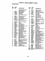
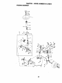
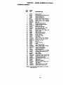
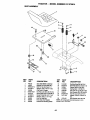
Repair Parts ........................................ 34
Parts Ordering ....................... Back Cover
LIMITED TWO YEAR WARRANTY ON CRAFTSMAN RIDING EQUIPMENT
For two (2) years from the date of purchase, if this Craftsman Riding Equipment is
maintained, lubricated and tuned up according to the instructions in the owner's
manual, Sears will repair or replace, free of charge, any parts found to be defective in
material or workmanship.
This Warranty does not cover:
• Expendable items which become worn during normal use, such as blades, spark
plugs, air cleaners, belts, etc.
• Tire replacement or repair caused by punctures from outside objects, such as nails,
thorns, stumps, or glass.
• Repairs necessary because of operator abuse, negligence, improper storage or accident or the failure to maintain the equipment according to the instructions contained
in the owner's manual.
• Riding equipment used for commercial or rental purposes.
LIMITED 90 DAY WARRANTY ON BATTERY
For ninety (90) days from date of purchase, if any battery included with this riding equipment proves defective in material or workmanship and our testing determines the battery will not hold a charge, Sears will replace the battery at no charge. In-home warranty service on your Craftsman riding equipment is available at no charge for 30 days
from the date of purchase. Please contact your nearest service center. After 30 days
from the date of purchase, warranty service is available by taking your Craftsman dding
equipment to your nearest Sears Service Center. (In-home warranty service will still be
available after 30 days from the date of purchase but a standard trip charge will apply).
This warranty applies only while this product is in the United States. This Warranty gives
you specific legal dghts, and you may also have other rights which may vary from state
to state.
Sears, Roebuck and Co., D/817 WA, Hoffman Estates, IL 60179
Be sure the area is clear of other
IMPORTANT: This cutting machine is
capable of amputating hands and feet and
throwing objects. Failure to observe the
following safety instructions could result in
serious injury or death.
GENERAL OPERATION
people before mowing. Stop machine if
anyone enters the area.
Never carry passengers.
Do not mow in reverse unless absolutely necessary. Always look down
and behind before and while backing.
Be aware of the mower discharge
direction and do not point it at anyone.
Do not operate the mower without
either the entire grass catcher or the
guard in place.
Slow down before turning.
• Read, understand, and follow all
instructions in the manual and on the
machine before starting.
• Only allow responsible adults, who are
familiar with the instructions, to operate
the machine.
• Clear the area of objects such as recks,
toys, wire, etc., which could be picked
up and thrown =by the blade.
2
DO NOT:
• Never leave a running machine
unattended. Always turn off blades, set
parking brake, stop engine, and
remove keys before dismounting.
• Turn off blades when not mowing.
• Stop engine before removing grass
catcher or unclogging chute.
• Mow only in daylight or good artificial
light.
• Do not operate the machine while
under the influence of alcohol or drugs.
• Watch for traffic when operating near
or crossing roadways.
• Use extra care when loading or
unloading the machine into a trailer or
truck.
• Do nottum on slopes unless necessary, and then, turn slowly and
gradually downhill, if possible.
• Do not mow near drop-offs, ditches, or
embankments. The mower could
suddenly tum over if a wheel is over
the edge of a cliff or ditch, or if an edge
caves in.
• Do not mow on wet grass. Reduced
traction could cause sliding.
• Do not try to stabilize the machine by
putting your foot on the ground.
• Do not use grass catcher on steep
slopes.
CHILDREN
• Data indicates that operators, age 60
years and above, are involved in a
large percentage of riding mowerrelated injudes. These operators
should evaluate their ability to operate
the riding mower safely enough to
protect themselves and others from
sedous injury.
SLOPE OPERATION
Tragic accidents can occur if the operator
is not alert to the presence of children.
Children are often attracted to the
machine and the mowing activity. Never
assume that children will remain where
you last saw them.
• Keep children out of the mowing area
and under the watchful care of another
responsible adult.
• Be aled and turn machine off if children
enter the area.
Slopes are a major factor related to lossof-control and tipover accidents, which
can result in severe injury or death. All
slopes require extra caution. If you
cannot back up the slope or if you feel
uneasy on it, do not mow it.
DO:
• Before and when backing, look behind
and down for small children.
• Never carry children. They may fall off
and be seriously injured or interfere
with safe machine operation.
• Never allow children to operate the
machine.
• Mow up and down slopes, not across.
• Remove obstacles such as rocks, tree
limbs, etc.
• Watch for holes, ruts, or bumps.
Uneven terrain could overturn the
• Use extra care when approaching blind
corners, shrubs, trees, or other objects
that may obscure vision.
SERVICE
machine. Tall grass can hide obstacles.
• Use slow speed. Choose a low gear so
that you will not have to stop or shift
while on the slope.
• Follow the manufacturer's recommendations for wheel weights or counterweights to improve stability.
• Use extra care with grass catchers or
other attachments. These can change
the stability of the machine.
• Keep all movement on the slopes slow
and gradual. Do not make sudden
changes in speed or direction.
• Avoid starting or stopping on a slope. If
tires lose traction, disengage the blades
and proceed slowly straight down the
slope.
•
Use extra care in handling gasoline
and other fuels. They are flammable
and vapors are explosive.
Use only an approved container.
Never remove gas cap or add fuel
with the engine running. Allow
engine to cool before refueling. Do
not smoke.
Never refuel the machine indoors.
Never store the machine or fuel
container inside where there is an
open flame, such as a water
heater.
• Never run a machine inside a closed
area.
3
• Keep nuts and bolts, especially blade
attachment bolts, tight and keep
equipment in good condition.
• Never tamper with safety devices.
Check their proper operation regularly.
• Keep machine free of grass, leaves, or
other debris build-up. Clean oil or fuel
spillage. Allow machine to cool before
storing.
• Stop and inspect the equipment if you
strike an object. Repair, if necessary,
before restarting.
• Never make adjustments or repairs with
the engine running.
• Grass catcher components are subject
to wear, damage, and deterioration,
which could expose moving parts or allow objects to be thrown. Frequently
check components and replace with
manufacturer's recommended parts,
when necessary.
• Mower blades are sharp and can cut.
Wrap the blade(s) or wear gloves, and
use extra caution when servicing them.
• Check brake operation frequently. Adjust and service as required.
• Be sure the area is clear of other people
• Mow up and down slopes (15 ° Max), not
before mowing. Stop machine if anyone
enters the area.
• Never carry passengers or children
even with the blades off.
• Do not mow in reverse unless absolutely necessary. Always look down and
behind before and while backing.
• Never carry children. They may fall off
and be seriously injured or interfere with
safe machine operation.
• Keep children out of the mowing area
and under the watchful cars of another
responsible adult.
• Be alert and tum machine off if children
• enter the area.
• Before and when backing, look behind
and down for small children.
across.
• Remove obstacles such as rocks, tree
limbs, etc.
• Watch for holes, ruts, or bumps. Uneven
terrain could overtum the machine. Tall
grass can hide obstacles.
• Use slow speed. Choose a low gear so
that you will not have to stop or shift
while on the slope.
• Avoid starting or stopping on a slope. If
tires lose traction, disengage the blades
and proceed slowly straight down the
slope.
• If machine stops while going uphill,
disengage blades, shift into reverse and
back down slowly.
• Do not tum on slopes unless necessary,
and then, tum slowly and gradually
downhill, if possible.
_CAUTION:
Tow only the attachments
that are recommended by and comply with
spocif'mationsof the manufacturer of your
tractor. Use common sense when towing.
Operate only at the lowest possible speed
_LCAUTION: In order to prevent acciden- when on a slope. Too heavy of a load, while
tal starting when setting up, transporting,
on a slope, is dangerous.Tires can lose
adjusting or making repairs always discon- traction with the ground and cause you to
nect spark plug wire and place wire where
lose control of your tractor.
it cannot contact spark plug.
_WARNING:
The anqine exhaust from
_CAUTION:
Do not coast down a hill in
this product contains chemicals known to
neutral, you may lose control of the tractor. the State of California to cause cancer,
_LLook for this sy.mbolto point out impor.
• tant safety pracadtions. It means CAUTIONt!! BECOME AWAREt!! YOUR
SAFETY IS INVOLVED.
4 birth defects, or other reproductive harm.
PRODUCT SPECIFICATIONS
MAINTENANCE
GASOLINE
CAPACITY
AND TYPE:
3.5 GALLONS
UNLEADED
REGULAR
A Sears Maintenance Agreement is available on this product. Contact your nearest
Sears store for details.
OIL TYPE
_PI-SF/SG/SH):
SAE 30 (above 32°F)
SAE 5W-30
(below32°1=)
CUSTOMER
01L CAPACITY:
3.0 PINTS
SPARK PLUG:
GAP: .030")
ChampionRJ19LM OR
J19LM
VALVE
CLEARANCE:
INTAKE: .004"-,006"
AWARNING: This tractor is equipped
EXHAUST:.007"-.009" with an internal combustion engine and
should not be used on or near any unimFORWARD:
proved forest-covered, brush-covered or
1sT
1.2
grass-covered land unless the engine's
2 ND
1.5
exhaust system is equipped with a spark
3 RD
2.3
arrester meeting applicable local or state
4TM
3.5
laws (if any). If a spark arrester is used, it
5TM
4.8
should be maintained in effective working
6 TM
5A
order by the operator.
REVERSE:
1.5
In the state of Califomia the above is reFRONT: 14 PSI
quired by law (Section 4442 of the CaliforREAR: 10 PSI
nia Public Resources Code). Other states
may have similar laws. Federal laws apply
3 AMPS BATTERY
on federal lands. A spark arrester for the
5 AMPS HEADLIGHTS
muffler is available through your nearest
AMP/HR:
30
Sears Authorized Service Center (See
MIN. CCA:
240
REPAIR PARTS section of this manual).
GROUND SPEED
(MPH):
TIRE PRESSURE:
CHARGING
SYSTEM:
ARTERY.'
RESPONSIBILITIES
• Read and observe the safety rules.
• Follow a regular schedule in maintaining, caring for and using your tractor.
• Follow the instructions under =Maintenance" and =Storage" sections of this
owner's manual.
CASE SIZE: U1R
BLADE BOLT
TORQUE:
AGREEMENT
27--35 FT.LBS.
I
CONGRATULATIONS on your purchase
of a Craftsman Tractor. It has been designed, engineered and manufactured to
give you the best possible dependability
and performance.
Should you experience any problem you
cannot easily remedy, please contact your
nearest Sears Authorized Service Center.
We have competent, well-trained technicians and the proper tools to service or repair this tractor.
Please read and retain this manual. The
instructions will enable you to assemble
and maintain your tractor properly. Always
observe the "SAFETY RULES".
5
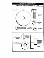
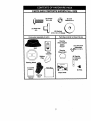
PARTS BAG CONTENTS
SHOWN FULL SIZE
(1) Large FlatWasher
(1) Hex Bolt
3/8-16 x 1
(1) Lockwasher
_8
(1) Hex Bolt
5/16-18x 1-1/4
@
(1) Locknut
5/16-18
(1) Shoulder Bolt
5/16-18
(I) Washer
17/32 x 1-3/16 x 12 Gauge
©
(1) Knob
6
PARTS BAG CONTENTS
(
_,
!
(2) Screws
_
_
#10 x 5/8
(2) Weld Nuts
#10
I
=,
SHOWN FULL SIZE
(2) Lock
_1_
Washers #10
(2) Washers
3/16 x 3/4 x 16 Gauge
Pads packet separately in carton
v
Pads Bag contents not shown full size
Steering
Wheel Adapter
(2) Latch Hook
Assemblies
Seat
Steedng
Wheel Insert
Video
Cassette
Mulcher iF_
C{,_I' _
, i
I Steedng
Extension
Shaft
Plata_
Pads Bag
Steering Whlae_
Manual
Steedng
Boot
i
I
s
i
i
I
I
I
',
'
1
=
Slope Sheet
7
(2) Keys
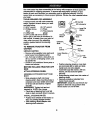
Your new tractor has been assembled at the factory with exception of those parts left
unassembled for shipping purposes. To ensure safe and proper operation of your
tractor all parts and hardware you assemble must be tightened securely. Use the
correct tools as necessary to insure proper tightness. Review the video cassette before
you begin.
TOOLS REQUIRED
FOR ASSEMBLY
A socket wrench set will make assembly
easier. Standard wrench sizes you need
are listed below.
(1) 9/16" wrench
(2) 1/2" wrench
(1) Phillips Screw(1) Pliers
driver
(1) Tire pressure
(1) Utility knife
gauge
(1) 3/4" socket with drive ratchet
When right or left hand is mentioned in
this manual, it means, from your point of
view, when you are in the operating
position (seated behind the steering
wheel).
TO REMOVE
CARTON
UNPACK
TRACTOR
FROM
CARTON
• Remove all accessible loose parts and
parts boxes from shipping carton.
• Cut, from top to bottom, along lines on
all four corners of shipping carton, and
lay panels flat.
• Check for any additional loose parts or
boxes and remove.
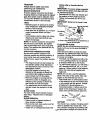
• Position steering wheel so cross bars
are horizontal (left to right) and slide
inside boot and onto adapter.
• Assemble large flat washer, 3/8 lock
washer, 3/8 hex bolt and tighten
securely.
• Snap steering wheel insert into center of
steering wheel.
• Remove protective materials from
tractor hoed and gdll.
IMPORTANT:
Check for and remove any
staples in skid that may puncture tires
where tractor is to roll off skid.
BEFORE ROLLING TRACTOR OFF
SKID
ATTACH
STEERING
WHEEL
ASSEMBLE EXTENSION SHAFT AND
BOOT
• Slide extension shaft onto lower
steering shaft. Align mounting holes in
extension and lower shafts and install
5/16 hex belt and Iocknut. Tighten
securely.
IMPORTANT: Tighten belt and nut
securely to 18-22 ft. Ibs. torque.
'• Place tabs of steering boot over tab
slots in dash and push down to secure.
INSTALL STEERING WHEEL
• Position front wheels of the tractor so
they are pointing straight forward.
• Slide steering wheel adapter onto
steedng shaft extension.
8
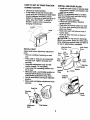
HOW TO SET UP YOUR TRACTOR
CONNECTBATTERY
• Lift hood to raised position.
• If this battery is put into service after
month and year indicated on label (label
located between terminals) charge
battery for minimum of one hour at 6-10
amps. (See "BATTERY" in MAINTENANCE section of this manual for
charging instructions).
÷÷- ,_//
,-
INSTALL
_...~
,
.,
Label
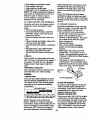
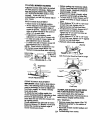
INSTALL MULCHER PLATE
• Install two latch hooks to mulcher plate
using screw, washer, lock washer, and
weld nut as shown.
NOTE: Pre-assemble weld nut to latch
hook by inserting weld nut from the top
with hook pointing down,
• Tighten hardware securely.
• Raise and hold deflector shield in
upright position.
• Place front of mulcher plate over front
of mower deck opening and slide into
place, as shown.
• Hook front latch into hole on front of
mower deck.
• Hook rear latch into hole on back of
mower deck.
_CAUTION:
Do not remove discharge
guard from mower. Raise and hold guard
when atlaching muicher plate and allow it
to rest on plate white in operation.
Weld Nut From
The Top
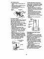
SEAT
Adjust seat before tightening adjustment
knob.
• Remove cardboard packing on seat
pan.
• Place seat on seat pan and assemble
shoulder bolt. Tighten shoulder bolt
securely.
• Assemble adjustment knob and flat
washer loosely. D ° not tighten.
• Lower seat into operating position and
sit on seal
• Slide seat until a comfortable position is
reached which allows you to press
clutch/brake pedal all the way down.
• Get off seat without moving its adjusted
Weld
Hook Points
Down
Look
Washer
Latch
Latch
JNut
Lock Washer
Washer
Washer
Mulcher
Plate
'_.._ Screw
Deflector
Shield
position.
• Raise seat and tighten adjustment knob
securely.
Seat
s ,0or\
}r-i
A_ustmen_t__=t
Latch
Hooks
Washer
Knob
9
V"CHECKLIST
TO CONVERT TO BAGGING OR
DISCHARGING
Simply remove mulcher plate and store in
a safe place. Your mower is now ready for
discharging or installation of optional
grass catcher accessory.
NOTE: It is not necessary to change
blades. The mulcher blades are designed
for discharging and bagging also.
CHECK TIRE PRESSURE
The tiros on your tractor were overinflated
at the factory for shipping purposes.
Correct tire pressure is important for best
cutting performance.
• Reduce tire pressure to PSI shown in
=PRODUCT SPECIFICATIONS" section
of this manual.
CHECK
DECK LEVELNESS
For best cutting results, mower housing
should be properly leveled. See "TO
LEVEL MOWER HOUSING" in the
Service and Adjustments
manual.
CHECK FOR PROPER
ALL BELTS
section of this
POSITION
OF
See the figures that are shown for
replacing motion and mower blade drive
belts in the Service and Adjustments
section of this manual. Verify that the belts
are routed correctly.
CHECK BRAKE SYSTEM
After you learn how to operate your
tractor, check to see that the brake is
properly adjusted. See "TO ADJUST
BRAKE" in the Service and Adjustments
section of this manual.
Before you operate and enjoy your new
tractor, we wish to assure that you receive
the best performance
and satisfaction
from this quality product.
Please review the following checklist:
,/ All assembly instructions have been
completed.
,/No remaining loose parts in carton.
,/Battery is properly prepared and
charged.(Minimum
1 hour at 6 amps).
4' Seat is adjusted comfortably and tightened securely.
,/All tires are propedy inflated. (For shipping purposes, the tires were overinflated at the factory).
•/ Be sure mower deck is properly leveled
side-to-side/front-to-rear
for best cutting
results. (Tires must be properly inflated
for leveling).
/ Check mower and drive belts. Be sure
they are routed properly around pulleys
and inside all belt keepers.
,/Check wiring. Sea that all connections
are still secure and wires are properly
clamped.
While learning how to use your tractor, pay
extra attention to the following important
items:
/ Engine oil is at proper level.
•/ Fuel tank is filled with fresh, clean, regular unleaded gasoline.
•/ Become familiar with all controls - their
location and function. Operate them before you start the engine.
/ Be sure brake system is in safe operating condition.
10
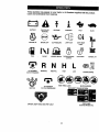
These symbols may appear on your tractor or in literature supplied with the product.
Leam and understand their meaning.
BATTERY
CAUTION OR
WARNING
REVERSE
FORWARD
FAST
ENGINE ON
ENGINE OFF
OIL PRESSURE
LIGHTS ON
FUEL
CHOKE
MOWER HEIGHT
PARKING BRAKE
LOCKED
SLOW
OVER TEMP
LIGHT
UNLOCKED
MOWER LIFT
H L
ATrACHMENT
CLUTCH ENGAGED
__)
REVERSE
NEUTRAL
LOW
PARKING. BRAKE
ATTACHMENT
IGNITION
HIGH
KEEP AREA CLEAR
CLUTCH DISENGAGED
SLOPE HAZARDS
(SEE SAFETY RULES SECTION)
Ei=
FREE WHEEL
(AutomaticModels only)
DANGER, KEEP HANDS AND FEET AWAY
11
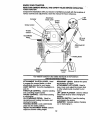
KNOW YOUR TRACTOR
, ....
_...... _.
:
_..... ,
_ , ,
R_DTHIS
OWNER'S MANUAL AND.SAF_
RULES BEFORE OPERATING
i_ _
YOUR TRACTOR ....
Compare the illustrations with your tractor to familiarize yourself with the locations of
various controls and adjustments. Save this manual for future reference.
Ammeter
Light
Attachment
Clutch Lever
.
\
ignmon
Choke Control
• •_
_ Switch
.s
Throttle
Control
Clutch/Brake
Pedal
Lift Lever
Plunger
Attachment Lift
Lever
Brake
Height
Adjustment
Knob
Gearshift
Lever
Our tractors conform to the safety standards of the American
National Standards Institute.
ATTACHMENT
CLUTCH
LEVER:
Used
to engage the mower blades, or other
attachments mounted to your tractor.
LIGHT SWITCH:
Turns the headlights on
and off.
THROTTLE
CONTROL:
Used for starting
and controlling engine speed.
CHOKE CONTROL:
Used when starting
a cold engine.
CLUTCH/BRAKE
PEDAL:
Used for
declutching and braking the tractor and
starting the engine,
PARKING BRAKE: Locks clutch/brake
pedal into the brake position.
HEIGHT ADJUSTMENT
KNOB:
adjust the mower cutting height.
GEARSHIFT
LEVER: Selects the speed
and direction of tractor.
ATTACHMENT
LIFT LEVER: Used to
raise, lower, and adjust the mower deck
or other attachments mounted to your
tractor.
LIFT LEVER PLUNGER:
Used to release
attachment lift lever when changing its
position.
IGNITION SWITCH:
Used for starting
and stopping the engine.
AMMETER:
Indicates battery charging
(+) or discharging (-).
Used to
12
The operation of any tractor can result in foreign objects thrown into the
eyes, which can result in severe eye damage. Always wear safety glasses or eye shields while operating your tractor or performing any adjustments or repairs. We recommend a wide vision safety mask over spectacles, or standard safety glasses.
HOW TO USE YOUR
TRACTOR
Your tractor is equipped with an operator
presence sensing switch. When engine
is running, any attempt by the operator to
leave the seat without first setting the
parking brake will shut off the engine.
TO SET PARKING BRAKE
• Depress clutch/brake pedal into full
=BRAKE" position and hold.
• Place parking brake lever in =ENGAGED" position and release pressure
from clutch/brake pedal. Pedal should
remain in =BRAKE"position. Make sure
parking brake will hold tractor secure.
Choke Control
Attachment Clutch Lever
"Engaged" Position
Throttle
Control
Position
Brake
/ "Engaged"
Position
Position
"Disengaged"
Position
Gearshift
Lever
Adjustment
Knob
Position
STOPPING
MOWER BLADES • To stop mower blades, move attachment clutch lever to =DISENGAGED"
position.
GROUND DRIVE • To stop ground ddve, depress clutch/
brake pedal into full =BRAKE" position.
• Move gearshift lever to neutral (N)
position.
ENGINE
-
• Move throttle control to slow position.
NOTE: Failure to move throttle control to
slow position and allowing engine to idle
before stopping may cause engine to
"backfire".
• Turn ignition key to =OFF" position and
remove key. Always remove key when
leaving tractor to prevent unauthorized
use.
• Never use choke to stop engine.
IMPORTANT: Leaving the ignitionswitch
in any position other than =OFF" will cause
the battery to be discharged, (dead).
NOTE: Under certain conditions when
tractor is standing idle with the engine
running, hot engine exhaust gases may
cause =browning" of grass. To eliminate
this possibility, always stop engine when
stopping tractor on grass areas.
A, CAUTION: Always stop tractor
completely, as described above, before
leaving the operator's position; to empty
grass catcher, etc.
THROTTLE CONTROL
Always operate engine at full throttle.
• Operating engine at less than full
throttle reduces the battery charging
rate.
• Full throttle offers the best bagging and
mower performance.
CHOKE CONTROL
Use choke control whenever you are
starting a cold engine. DO not use to start
a warm engine.
• To engage choke control, pull knob out.
Slowly push knob in to disengage.
TO MOVE FORWARD AND BACKWARD
The direction and speed of movement is
controlled by the gearshift lever.
• Start tractor with clutch/brake pedal
depressed and gearshift lever in neutral
(N) position.
• Move gearshift lever to desired position.
* Slowly release clutch/brake pedal to
start movement.
IMPORTANT: Bring tractor tOa complete
stop before shifting or changing gears.
Fa'durs to do so will shorten the useful life
of your transaxle.
13
TO ADJUST MOWER CUTTING HEIGHT
TO OPERATE
The cutting height is controlled by tuming
the height adjustment knob in desired
direction.
• Turn knob clockwise (r_) to raise cutting
height.
• Tum knob countemlockwise (_,_)to
lower cutting height.
The cutting height range is approximately
1-1/2" to 4 =. The heights are measured
from the ground to the blade tip with the
engine not running. These heights are
approximate and may vary depending
upon soil conditions, height of grass and
types of grass being mowed.
• The average lawn should be cut to
approximately 2-1/2 inches during the
cool season and to over 3 inches during
hot months. For healthier and better
looking lawns, mow often and after
moderate growth.
• For best cutting performance, grass
over 6 inches in he!ght should be
mowed twice. Make the first cut
relatively high; the second to desired
height.
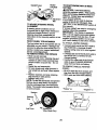
TO ADJUST GAUGE WHEELS
Gauge wheels are properly adjusted
when they are slightly off the ground when
mower is at the desired cutting height in
operating position. Gauge wheels then
keep the deck in proper position to help
prevent scalping in most terrain conditions.
• Adjust gauge wheels with tractor on a
fiat level surface.
• Adjust mower to desired cutting height
(See "TO ADJUST MOWER CUTTING
HEIGHT" in the Operation section of this
manual).
• With mower in desired height of cut
position, gauge wheels should be
assembled so they are slightly off the
ground. Install gauge wheel in appropriate hole with shoulder bolt, 3/8 washer,
and 3/8-16 Iocknut and tighten securely.
• Repeat tot opposite side installing
gauge wheel in same adjustment hole.
Gauge Wheel
Your tractor is equipped with an operator
presence sensing switch. Any attempt by
the operator to leave the seat with the
engine running and the attachment clutch
engaged will shut off the engine.
• Select desired height of cut.
• Lower mower with attachment lift
control.
Mounting
Bracket
• Start mower blades by engaging
attachment clutch control.
• TO STOP MOWER BLADES - disengage attachment clutch control.
_CAUTION:
Do not operate the mower
without either the entire grass catcher, on
mowers so equipped, or the discharge
guard in place.
Attachment Clutch
Gauge Wheel
Attachment Lift Lever
Leve r "Engaged"F_-_-- _ High Position
Positi_n_.
_
.
=Disengaged"
____Low
Position
TO OPERATE
__.__4"--N
Position
ON HILLS
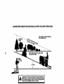
_CAUTION:
DO not drive up or down hills
with slopes greater than 15 ° and do not
drive across any slope. A slope guide at
the back of your manual is provided for
your use.
• Choose the slowest speed before
starting up or down hills.
• Avoid stopping or changing speed on
hills.
• It slowing is necessary, move throttle
control lever to slower position.
• If stopping is absolutely necessary, push
clutch/brake pedal quickly to brake
position and engage parking brake.
• Move gearshift lever to 1st gear. Be
sure you have allowed room for tractor
to roll slightly as you restart movement.
• To restart movement, slowly release
parking brake and clutch/brake pedal.
• Make all turns slowly.
3/8-16
Locknu
3/8 Washel
MOWER
Shoulder
14
TO TRANSPORT
ADD GASOLINE
• Raise attachment liftto highest position
with attachment lift control.
• When pushing or towing your tractor,
be sure gearshift lever is in neutral (N)
position.
• Do not push or tow tractor at more than
five (5) MPH.
NOTE: To protect hood from damage
when transporting your tractor on a truck
or a trailer, be sure hood is closed and
secured to tractor. Use an appropriate
means of tying hood to tractor (rope, cord,
etc.).
TOWING CARTS AND OTHER ATTACHMENTS
• RII fuel tank. Use fresh, clean, regular
unleaded gasoline with a minimum of
87 octane. (Use of leaded gasoline will
increase carbon and lead oxide
deposits and reduce valve life). Do not
mix oil with gasoline. Purchase fuel in
quantities that can be used within 30
days to assure fuel freshness.
IMPORTANT:
When operating in temperatures below 32°F(0°C), use fresh,
clean winter grade gasoline to help insure
good cold weather starting.
_I_WARNING:
Experience indicates that
alcohol blended fuels (called gssohol or
using ethanol or methanol) can attract
moisture which leads to separation and
formation of acids during storage. Acidic
gas can damage the fuel system of an
engine while in storage. To avoid engine
problems, the fuel system should be
emptied before storage of 30 days or
longer. Drain the gas tank, start the
engine and let it run until the fuel lines
and carburetor are empty. Use fresh fuel
next season. See Storage Instructions for
additional information. Never use engine
or carburetor cleaner products in the fuel
tank or permanent damage may occur.
• I_CAUTION: Fill to bottom of gas tank
filler neck. Do not overfill. Wipe off any
spilled oil or fuel. Do not store, spill or use
gasoline near an open flame.
Tow only the attachments that are
recommended by and comply with
specifications of the manufacturer of your
tractor. Use common sense when towing.
Too heavy of a load, while on a slope, is
dangerous. Tires can lose traction with
the ground and cause you to lose control
of your tractor.
BEFORE
CHECK
STARTING
ENGINE
THE
ENGINE
OIL LEVEL
• The engine in your tractor has been
shipped, from the factory, already filled
with summer weight oil.
• Check engine oil with tractor on level
ground.
• Remove oil fill cap/dipstick and wipe
clean, reinsert the dipstick and screw
cap tight, wait for a few seconds,
remove and read oil level. If necessary,
add oil until =FULL" mark on dipstick is
reached. Do not overfill
• For cold weather operation you should
change oil for easier starting (See "OIL
VISCOSITY
CHART" in the Maintenance section of this manual).
• To change engine oil, see the Maintenance section in this manual.
15
TO START ENGINE
When starting the engine for the first time
or if the engine has run out of fuel, it will
take extra cranking time to move fuel from
the tank to the engine.
• Sit on seat in operating position,
depress clutch/brake pedal and set
parking brake.
• Place gear shift lever in neutral (N)
position.
• Move attachment clutch to =DISENGAGED" position.
• Move throttle control to fast position
• Pull choke control out for a cold engine
start attempt. For a warm engine start
attempt the choke control may not be
needed.
NOTE: Before starting, read the warm
and cold starting procedures below.
• Insert key into ignition and turn key
clockwise to =START" position and
release key as soon as engine starts.
Do not run starter continuously for more
than fifteen seconds per minute. If the
engine does not start after several
attempts, push choke control in, wait a
few minutes and try again. If engine still
does not start, pull the choke control out
and retry.
WARM WEATHER
AND ABOVE)
STARTING
COLD WEATHER STARTING (50 ° F AND
BELOW)
• When engine starts, slowly push choke
control in until the engine begins to run
smoothly. Continue to push the choke
control in small steps allowing the
engine to accept small changes in
speed and load, until the choke control
is fully in. If the engine starts to run
roughly, pull the choke control out
slightlyfor a few seconds and then
continue to push the control in slowly.
This may require an engine warm-up
period from several seconds to several
minutes, depending on the temperature.
• The attachments can be used dudng
the engine warm-up period and may
require the choke control be pulled out
slightly.
NOTE: A high altitude (above 3000 feet)
or in cold temperatures (below 32 F) the
carburetor fuel mixture may need to be
adjusted for best engine performance.
See "TO ADJUST CARBURETOR" in the
Service and Adjustments section of this
manual.
(50 ° F
• When engine starts, slowly push choke
control in until the engine begins to run
smoothly. If the engine starts to run
roughly, pull the choke control out
slightly for a few seconds and then
continue to push the control in slowly.
• The attachments and ground drive can
now be used. If the engine does not
accept the load, restart the engine and
allow it to warm up for one minute using
the choke as descdbed above.
16
MOWING TiPS
• .Tire chains cannot be used when the
mower housing is attached to tractor.
• Mower should be properly leveled for
best mowing performance. See "TO
LEVEL MOWER HOUSING" in the
Service and Adjustments section of this
manual.
• The left hand side of mower should be
used for trimming.
• Drive so that clippings are discharged
onto the area that has been cut. Have
the cut area to the right of the machine.
This will result in a more even distribution of clippings and more uniform
cutting.
• When mowing large areas, start by
turning to the right so that clippings will
discharge away from shrubs, fences,
driveways, etc. After one or two
rounds,
mow in the opposite direction making
left hand turns until finished
• If grass is extremely tall, it should be
mowed twice to reduce load and
possible fire hazard from dried clippings. Make first cut relatively high; the
second to the desired height.
• Do not mow grass when it is wet. Wet
grass will plug mower and leave
undesirable clumps. Allow grass to dry
before mowing.
• Always operate engine at full throttle
when mowing to assure better mowing
performance and proper discharge of
material. Regulate ground speed by
selecting a low enough gear to give the
mower the best cutting performance as
well as the quality of cut desired.
• When operating attachments, select a
ground speed that wilt suit the terrain
and give best performance of the
attachment being used.
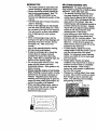
MULCHING
MOWING TIPS
IMPORTANT. For best performance,
keep mower housing free of built-up gras.=
and trash. Clean after each use.
• The special mulching blade will recut
the grass clippings many times and
reduce them in size so that as they fall
onto the lawn they will disperse into the
grass and not be noticed. Also, the
mulched grass will biodegrade quickly t_
provide nutrients for the lawn. Always
mulch with your highest engine (blade)
speed as this will provide the best
recutting action of the blades.
Avoid cutting your lawn when it is wet.
Wet grass tends to form clumps and
interferes with the mulching action. The
best time to mow your lawn is the early
afternoon. At this time the grass has
dried and the newly cut area will not be
exposed to the direct sun.
For best results, adjust the mower
cutting height so that the mower cuts off
only the top one-third of the grass
blades. For extremely heaW mulching,
reduce your width of cut on each pass
and mow slowly.
Certain types of grass and grass
conditions may require that an area be
mulched a second time to completely
hide the clippings. When doing a
second cut, mow across or perpendicular to the first cut path.
Change your cutting pattem from week
to week. Mow north to south one week
then change to east to west the next
week. This will help prevent matting
and graining of the lawn.
17
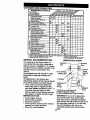
CUSTOMER RESPONSIBILITIES
MAINTENANCE SCHEDULE
=.._./_._j_
o.__o__.
Check'nm _m
iT
Inmrlo_Systems
I/
R Chock
_ L=o_F==o,_m
Lubd_on
R
_
_,
Chart
_
Clean Batteryand Terminals
! I_
CheckTransaxleCooling
I_
Adjust Motion D_ve Belt(s) Tewsion
Ch_ _,_ C_Lo_
E
_s
_
Clean AirFilter
N c_=n_UrS¢r=m
I_
ReplaceOil Filter(If equipped)
l_.i
Replace Spark Plug
_i
ReplaceAft FilterPiper Cllrtddge
II_=
EN CleanEngineCoolk_g
Fins
1. Clwlge nlonl oitlll idllm opitilig
2. Semite mor_ ofl_ whe. _)r_lng
3. _ equlpp_ with ol _,
GENERAL
ulidw ii Ilelvy load or in htgtl _lnl
b _ln'y o* du_y cotillions,
ch_m_e ol _
tlil_1_rldu_lil.
SO hounk
Check engine oil level.
Check brake operation.
Check tire pressure.
Check operator presence and interlock
systems for proper operation.
• Check for loose tasteners.
S - ff equipped _h _p_ble
=y_er_
il - Noi tequiiid II liqulpplid tilh n_illilimm_e-hlie bii_y,
7 - T_llt_m fro_ _le picot boltto _ ft,-Ib_ mmdmum.
LUBRICATION CHART
RECOMMENDATIONS
The warranty on this tractor does not
cover items that have been subjected to
operator abuse or negligence. To receive
full value from the warranty, operator must
maintain tractor as instructed in this
manual.
Some adjustments will need to be made
periodically to propedy maintain your
tractor.
All adjustments in the Service and
Adjustments section of this manual should
be checked at least once each season.
• Once a year you should replace the
spark plug, clean or replace air filter,
and check blades and belts for wear. A
new spark plug and clean air filter
• assure proper air-fuel mixture and help
your engine run better and last longer.
BEFORE EACH USE
•
•
•
•
V'
Zerk
Zerk
Wheel
Besdng
Zerk
_) Front Wheel
Bearing Zerk
® Engine
|
Attachment_ :
Clutch
I 'I
Pivot(s)
(I) SAE 30 or 10w30 Motor OIL
l
I
I
i
Pivots
@ GeneralPurposeGrease
Referto Maintenance"Engine" Section
IMPORTANT:
Do not oil or grease the
pivot points which have special nylon
bear-ings. Viscous lubricants will attract
dust and dirt that will shorten the life of the
self-lubricating bearings. If you feel they
must be lubricated, use only a dry,
powdered graphite type lubricant spar18 ingly"
TRACTOR
Always observe safety rules when
performing any maintenance.
BRAKE
OPERATION
If tractor requires more than six (6) feet
stopping distance at high speed in highest
gear, then brake must be adjusted. (See
=TO ADJUST BRAKE" in the Service and
Adjustments
TIRES
section of this manual).
• Maintain proper air pressure in aU tires
(See "PRODUCT SPECIFICATIONS"
section of this manual).
• Keep tires free of gasoline, oil, or insect
control chemicals which can harm
rubber.
• Avoid stumps, stones, deep ruts, sharp
objects and other hazards that may
cause tire damage.
NOTE: To seal tire punctures and prevent
flat tires due to slow leaks, tire sealant
may be purchased from your local parts
dealer. Tire sealant also prevents tire dry
rot and corrosion.
OPERATOR
PRESENCE SYSTEM
Be sure that operator presence and
interlock systems are working propedy. If
your tractor does not function as described below, repair the problem immediately.
• The engine should not start unless the
clutch/brake pedal is fully depressed
and attachment clutch control is in the
disengaged position.
• When the engine is running, any
attempt by the operator to leave the
seat without first setting the parking
brake should shut off the engine.
• When the engine is running and the
attachment clutch is engaged, any
attempt by the operator to leave the
seat should shut off the engine.
• The attachment clutch should never
operate unless the operator is in the
seat.
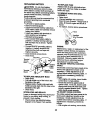
BLADE CARE
For best results mower blades must be
kept sharp. Replace bent or damaged
blades.
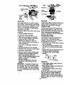
BLADE REMOVAL
• Raise mower to highest position to
allow access to blades.
• Remove hex bolt, lock washer and flat
washer securing blade.
• Install new or resharpened blade with
trailing edge up towards deck as
shown.
IMPORTANT: To ensure proper assembly,
center hole isn blade must align with star
on mandrel assembly.
• Reassemble hex bolt, lock washer and
flat washer in exact order as shown.
• Tighten bolt securely (27-35 Ft. Lbs.
torque).
IMPORTANT: Blade bolt is Grade 8 heat
treated.
TrailingEdge,
Center
Hole
MandrelAssembly
Flat Washer
Lock
_-Hex Bolt (Grade 8)
*A Grade 8 heat treated boltcan be identifiedby six
lines on the bolt head.
TO SHARPEN
BLADE
NOTE: We do not recommend sharpening
blade, but if you do, be sure the blade is
balanced.
Care should be taken to keep the blade
balanced. An unbalanced blade will cause
excessive vibration and eventual damage
to mower and engine.
• The blade can be sharpened with a file
or on a grinding wheel. Do not attempt
to sharpen while it is on the mower.
• To check blade balance, you will need a
5/8" diameter steel bolt, pin, or a cone
balancer. (When using a cone balancer,
follow the instructions supplied with
balancer).
NOTE: Do not use a nail for balancing
blade. The lobes of the center hole may
appear to be centered, but are not.
• Slide blade onto an unthreaded portion
of the steel bolt or pin and hold the belt
or pin parallel with the ground. If blade
is balanced, it should remain in a
horizontal position. If either end of the
blade moves downward, sharpen the
heavy end until the blade is balanced.
//
5/8" Bolt _
Blade
or Pin _
BATTERY
Your tractor has a battery charging system
which is sufficient for normal use. However, periodic charging of the battery with
19 an automotive charger will extend its life.
• Keep battery and terminalsclea n.
• Keep battery bolts tight.
_
• Keep small vent holes open.
• Recharge at 6-10 amperes for1 hour.
NOTE: The original equipment battery on
your tractor is maintenance free. Do not
attempt to open or remove caps or
covers. Adding or checking level of
electrolyte is not necessary.
TO CLEAN
BATTERY
AND TERMINALS
Corrosion and dirt on the battery and terminals can cause the battery to =leak"
power.
• Remove terminal guard.
• Disconnect BLACK battery cable first
then RED battery cable and remove
battery from tractor.
• Rinse the battery with plain water and
dry.
• Clean terminals and battery cable ends
with wire brush until bright.
• Coat terminals with grease or petroleum
jelly.
• Reinstall battery (See "REPLACING
BATTERY" in the SERVICE AND
ADJUSTMENTS
section of this manual).
V-BELTS
Check V-belts for deterioration
and wear
after 100 hours of operation and replace if
necessary. The belts are not adjustable.
Replace belts if they begin to slip from
wear.
TRANSAXLE
engine damage from running low on 0il.
Change the oil after every 25 hours of :
operation or at least once a year Jfthe
tractor is not used for 25 hours in one
year.
Check the crankcase oil level before
starting the engine and after each eight
(8) hours of operation. Tighten oil fill cap/
dipstick securely each time you check the
oil level.
TO CHANGE
ENGINE
Determine temperature range expected
before oil change, All oil must meet API
service classification SF, SG or SH.
• Be sure tractor is on level surface.
• Oil will drain more freely when warm.
• Catch oil in a suitable container.
• Remove oil fill cap/dipstick. Be careful
not to allow dirt to enter the engine
when changing oil.
• Remove drain plug.
• After oil has drained completely,
replace oil drain plug and tighten
securely.
• Refill engine with oil through oil fill
dipstick tube. Pour slowly. Do not
overfill. For approximate capacity see
=PRODUCT SPECIFICATIONS"
section
of this manual.
• Use gauge on oil fill cap/dipstick for
checking level. Be sure dipstick cap is
tightened securely for accurate reading.
Keep oil at "FULL" line on dipstick.
COOLING
Keep transaxle free from build-up of dirt
and chaff which can restrict cooling.
OIL
Air Screen
Oil
Plug
ENGINE
LUBRICATION
Only use high quality detergent oil rated
with API service classification SF, SG or
SH. Select the oil's SAE viscosity grade
according to your expected operating
temperature.
NOTE: Although multi-viscosity oils
(5W30, 10W30 etc.) improve starting in
cold weather, these multi-viscosity oils will
result in increased oil consumption when
used above 32°F. Check your engine oil
level more frequently to avoid possible
Oil
CLEAN
AIR-SCREEN
Air screen must be kept free of dirt and
chaff to prevent engine damage from
overheating. Clean with a wire brush or
compressed air to remove dirt and
stubborn dried gum fibers.
ENGINE COOLING RNS
Remove any dust, dirt or oil from engine
cooling fins to prevent engine damage
from overheating. Air guide covers must
be removed. Remove side panels and
hood (See =TO REMOVE HOOD AND
GRILL ASSEMBLY" in the Service and
Adjustments
2O
section of this manual).
Cover
Knob
Plate
Wing Nut
Foam
Pre-Cleaner
Air q
Cover
(Both
Sides)
Air Scre_
MUFFLER
AIR FILTER
Your engine will not run properly using a
dirty air filter. Clean the foam pre-cleaner
after every 25 hours of operation or every
season. Service paper cartridge every
100 hours of operation or every season,
whichever occurs first.
Service air cleaner more often under dusty
conditions.
• Remove knob(s) and cover.
TO SERVICE PRE-CLEANER
• Slide foam pre-cleaner off cartridge.
• Wash it in liquid detergent and water.
• Squeeze it dry in a clean cloth.
• Saturate it in engine oil. Wrap it in
clean, absorbent cloth and squeeze to
remove excess oil.
• If very dirty or damaged, replace precleaner.
• Reinstall pre-cleaner over cartridge.
• Reinstall cover and secure with knob(s).
TO SERVICE
Cartddge
CARTRIDGE
• Remove wing nuts and cartridge plate.
• Carefully remove cartridge to prevent
debris from entering carburetor.
• Clean cartridge by tapping gently on flat
surface. If very dirty or damaged,
replace cartridge.
• Reinstall cartridge plate, wing nuts,
precleaner, cover and secure with
knob(s).
IMPORTANT:
Petroleum solvents, such
as kerosene, are not to be used to clean
the cartridge. They may cause deterioration of the cartridge. Do not oil cartridge.
Do not use pressurized air to clean or dry
cartridge,
Inspect and replace corroded muffler and
spark arrester (if equipped) as it could
create a fire hazard and/or damage.
SPARK PLUGS
Replace spark plugs at the beginning of
each mowing season or after every 100
hours of operation, whichever occurs first.
Spark plug type and gap setting are
shown in =PRODUCT SPECIFICATIONS _
section of this manual,
IN-LINE FUEL FILTER
The fuel filter should be replaced once
each season, if fuel filter becomes
clogged, obstructing fuel flow to carburetor, replacement is required.
• With engine cool, remove filter and plug
fuel line sections.
• Place new fuel filter in positio n in fuel
line with arrow pointing towards carburetor.
• Be sure there are no fuel line leaks and
clamps are properly positioned.
• Immediately wipe up any spilled
gasoline.
CLEANING
• Clean engine, battery, seat, finish, etc.
of all foreign matter.
• Keep finished surfaces and wheels free
of all gasotine, oil, etc.
• Protect painted surfaces with automotive type wax.
We do not recommend using a garden
hose to clean your tractor unless the
electrical system, muffler, air filter and
carburetor are covered to keep water out.
Water in engine can result in a shortened
engine life.
21
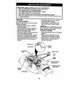
AqI_CAUTION: Before performing any service or adjustments:
• Depress clutch/brake pedal fully and set parking brake.
• Place gearshift lever in neutral (N) position.
• Place attachment clutch in =DISENGAGED" position.
• Turn ignition key *OFF" and remove key.
• Make sure the blades and all moving parts have completely stopped.
• Disconnect spark plug wire from spark plug and place wire where it cannot come
in contact with plug:
TRACTOR
TO REMOVE MOWER
Mower will be easier to remove from the
right side of tractor.
• Place attachment clutch in =DISENGAGED _ position.
• Move attachment lift lever forward to
lower mower to its lowest position.
• Roll belt off engine pulley.
• Disconnect clutch rod from clutch lever
by removing retainer spring.
• Disconnect anti-swaybar from chassis
bracket by removing retainer spdng,
• Disconnect suspension arms from rear
deck brackets by removing retainer
spdngs.
• Disconnect front links from deck by
removing retainer springs.
• Raise lift lever to raise suspension
arms. Slide mower out from under
tractor.
IMPORTANT: If an attachment other than
the mower deck is to be mounted on the
tractor, remove the front links.
TO INSTALL MOWER
• Raise attachment lift lever to its highest
position,
• Slide mower under tractor with discharge guard to right side of tractor.
• Lower lift lever to its lowest position.
• Install mower in reverse order of
removal instructions.
Retainer
Pulley
Arms
Front
Link
Retainer Springs
(Both Sides)
Retainer Spdngs
(Both Sides)
Retainer
Spring
AnU-Swaybar
22
TO LEVEL
MOWER
HOUSING
• Before making any necessary adjustments, check that both front links are
equal in length. Both links should be
approximately 10-3/8".
• If links are not equal in length, adjust
one link to same length as other link.
• To tower front of mower loosen nut =E"
on both front links an equal number of
tums.
• When distance "D" is 1/8" to 1/2" lower
at front than rear, tighten nuts =P'
against trunnion on both front links.
• To raise front of mower, loosen nut =F"
from trunnion on both front links.
Tighten nut =E" on both front links an
equal number of tums.
• When distance =D" is 1/8" to 1/2" lower
at front than rear, tighten nut =F" against
trunnion on both front links.
• Recheck side-to-side adjustment.
Adjust the mower while tractor is parked
on level ground or driveway. Make sure
tires are properly inflated (See =PRODUCT SPECIFICATIONS" section of this
manual). If tires are over or
underinflated, you will not properly adjust
your mower.
SIDE-TO-SIDE ADJUSTMENT
• Raise mower to its highest position.
• At the midpoint of both sides of mower,
measure height from bottom edge of
mower to ground. Distance =A" on both
sides of mower should be the same or
within 1/4" of each other.
• If adjustment is necessary, make
adjustment on one side of mower only.
• To raise one side of mower, tighten lift
link adjustment nut on that side.
• To lower one side of mower, loosen lift
link adjustment nut on that side.
NOTE: Each full turn of adjustment nut
will change mower height about 1/8".
• Recheck measurements after adjusting.
Bottom Edge
of Mower to _
A|
/
_
_/_-_t
U Ground Line U
(_
Mandrel
Bottom Edge
Mower to
Both Front Links Should be Equal in Length
! ;_A
Suspension
t=E•
Lift Unk Adjustment Nut
FRONT-TO-BACK ADJUSTMENT
IMPORTANT: Deck must be level side-toside. If the following front-to-back adjustment is necessary, be sure to adjust both
front links equally so mower will stay
level side-to-side.
To obtain the best cutting results, the
mower housing should be adjusted so that
the front is approximately 1/8" to 1/2"
lower than the rear when the mower is in
its highest position.
Check adjustment on right side of tractor.
Measure distance "D" directly in front and
behind the mandrel at bottom edge of
mower housing as shown.
Front Unks
TO REPLACE MOWER BLADE DRIVE
BELT (See Illustration Next Page)
The mower blade dri';'ebelt rpay be
replaced without tools. Park the tractor on
level surface. Engage parking brake.
BELT REMOVAL
-
• Remove mower from tractor (See =TO
REMOVE MOWER" in this section of
this manual).
• Work belt off both mandrel pulleys and
idler pulleys.
23" Pull belt away from mower.
BELT INSTALLATION • Install new belt in reverse order of removal.
• Make sure belt is in all pulley grooves
and inside all belt guides.
• Instafl mower in reverse order of removal instructions.
Mandrel
Idler Pulleys
TO ADJUST BRAKE
Your tractor is equipped with an adjustable
brake system which is mounted on the
rightside of the transaxle.
If tractor requires more than six (6) feet
stopping distance at high speed in highest
gear, then brake must be adjusted.
• Depress clutch/brake pedal and engage
parking brake.
• Measure distance between brake
operating arm and nut =A" on brake rod.
• If distance is other than 1-1/2", loosen
jam nut and turn nut "A" until distance
becomes 1-1/2". Retighten jam nut
against nut "A".
• Road test tractor for proper stopping
distance as stated above. Readjust if
necessary. If stopping distance is still
greater than six (6) feet in highest gear,
further maintenance is necessary.
Contact your nearest authorized
service center/department.
.=17
°°°"
i/j
With parking Brake
_perating
• TO REPLACE MOTION DRIVE BELT
Park the tractor on level surface. Engage
parking brake. For assistance, there is a
belt installation guide decal on bottom
side of left footrest.
• Remove mower (See "TO REMOVE
MOWER" in this section of this manual.)
• Remove belt from stationary idler and
clutching idler.
• Pull belt slack toward rear of tractor.
Remove belt upwards from transaxle
pulley by deflecting belt keepers.
• Pull belt toward front of tractor and
remove downwards from around engine
pulley.
• Install new belt by reversing above
procedure.
Engine
Pulley_
Clutching.---Idler
Stationary/
Idler
Transaxle
Pulley
TRANSAXLE
___
GEAR SHIFT LEVER
ADJUSTMENT
The transaxle should be in neutral when
the gear shift lever is in neutral (N) (lock
gate) position. The adjustment is preset at
the factory; however, if adjustment is
needed, proceed as follows:
• Make sure transaxle is in neutral (N).
NOTE: When the tractor rear wheels
move freely, the transaxle is in neutral.
• Loosen adjustment belt in front of the
right rear wheel.
• Position the gear shift lever in the
neutral (N) position.
• Tighten adjustment bolt securely.
NOTE: If additional clearance is needed
to get to adjustment belt, move mower
deck height to the lowest position.
Arm
24
TO START ENGINE WITH A WEAK
BATTERY
_CAUTION:
Lead-acid batteries
generate explosive gases. Keep sparks,
flame and smoking materials away from
batteries. Always wear eye protection
when around batteries.
Adiustment I! your battery is too weak to start the
/ ._'.
I
Bolt
engine, it should be recharged. (See
'BATTERY" in the MAINTANCE section o
TO ADJUST STEERING WHEEL
this manual).
ALIGNMENT
11"jumper cables" are used for emergenc,
If steedng wheel crossbars are not
starting, follow this procedure:
horizontal (left to right) when wheels are
IMPORTANT: Your tractor Is equipped
positioned straight forward, remove
with a 12 volt negative grounded system.
steedng wheel end reassemble per
The other vehicle must also be a 12 volt
instructions in the Assembly section of this negative grounded system. Do not use
manual.
your tractor battery to start other vehicles.
FRONT WHEEL TOE-IN/CAMBER
TO ATTACH JUMPER CABLES The front wheel toe-in and camber are not
• Connect each end of the RED cable to
adjustable on your tractor, if damage has
the POSITIVE (+) terminal of each
occurred to affect the front wheel toe-in or
battery, taking care not to short against
camber, contact your nearest authorized
chassis.
service center/department.
• Connect one end of the BLACK cable t_
TO REMOVE WHEEL FOR REPAIRS
the NEGATIVE (-) terminal of fully
• Block up axle securely.
charged battery.
• Remove axle cover, retaining dng and
• Connect the other end of the BLACK
washers to allow wheel removal (rear
cable to good CHASSIS GROUND,
wheel contains a square key - Do not
away from fuel tank and battery.
lose).
TO REMOVE CABLES, REVERSE
• Repair tire and reassemble.
ORDER • On roar wheels only: align grooves in
• BLACK cable first from chassis and
rear wheel hub and axle. Insert square
Gearshift Lever
Neutral
Lock Gate
/.,"
key.
• Replace washers and snap retaining
ring securely in axle groove.
• Replace axle cover.
NOTE: To seal tire punctures and prevent
flat tires due to slow leaks, tire sealant
may be purchased from your local parts
dealer. Tire sealant also prevents tire dry
rot and corrosion.
then from the fully charged battery.
• RED cable last from both battedes.
=Positive" (+)
Washers
Retaining
Ring
I
Axle Cover
Square Key
(Rear Wheel Only)
25
"Negative" (-}
REPLACING
BATTERY
,
_
_CAUTION:
Do not short battery'
: :
terminals by allowing a wrench or any
other object to contact both terminals at
the same time. Before connecting battery,
remove metal bracelets, wristwatch
bands,rings,etc.
Positive terminal must be connected first
to prevent sparking from accidental
grounding.
• Lift hood to raised position.
• Remove terminal guard:
• Disconnect BLACK battery cable then
RED battery cable and carefully remove
battery from tractor.
• install new battery with terminals in
same position as old battery.
• Reinstall terminal guard.
• First connect RED battery cable to
positive (+) battery terminal with hex
bolt and keps nut as shown. Tighten
securely.
• Connect BLACK grounding cable to
negative (-) battery terminal with
remaining hex bolt and keps nut.
Tighten securely.
• Close terminal access doors.
• Close hood.
Positive
Cable
Terminal
Guard
Cable
TO REPLACE HEADLIGHT BULB
• Raise hood.
• Pull bulb holder out of the hole in the
backside of the gdll.
• Replace bulb in holder and push bulb
holder securely back into the hole in the
backside of the grill.
• Close hood.
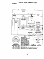
INTERLOCKS AND RELAYS
Loose or damaged wiring may cause your
tractor to run poorly, stop running, or
prevent it from starting.
• Check wiring. See electrical wiring
diagram in the Repair Parts section.
TO REPLACE FUSE
Replace with 30 amp automotive-type
plug-in fuse; The fuse holder is located
behind the dash.
TO REMOVE HOODAND GRILL
ASSEMBLY
• Raise hood.
• Unsnap headlight wire connector.
• Stand in front of tractor. Grasp hood at
sides, tilt toward engine and lift off of
tractor.
• To replace, reverse above procedures.
Connector
ENGINE
Maintenance, repair, or replacement of the
emission control devices and systems,
which are being done at the customers
expense, may be performed by any nonroad engine repair establishment or
individual. Warranty repairs must be
performed by an authorized engine
manufacturer's service outlet.
TO ADJUST THRO't'rLE
CONTROL
CABLE
The throttle control has been preset at the
factory and adjustment should not be
necessary. Check adjustment as described below before loosening cable. If
adjustment is necessary, proceed as
follows:
• With engine not running, move throttle
control lever to fast position.
• Check that swivel is against side of
quarter circle. If it is not, loosen cable
clamp screw and pull cable back until
swivel is against quarter circle. Tighten
cable clamp screw securely.
TO ADJUST CHOKE CONTROL
The choke control has been preset at the
factory and adjustment should not be
necessary. Check adjustment as described below before loosening cable. If
adjustment is necessary, proceed as
follows:
• With engine not running, move choke
26
• €0niroi (l_tecI-Qri €!ashpanel) to full_'
.Choke position.
"
- "o Remove air cleaner cover, filter and
cartddge plate to expose carburetor
choke (see =AIR FILTER" in the
Maintenance section of this manual).
• Choke should be closed. If it is not,
loosen casing clamp screw and move
choke cable untilchoke is completely
closed. Tighten casing clamp screw
securely.
• Reassemble air cleaner.
Choke CI_
Screw "L
_
_q"A-'-_ Choke Lever
TO ADJUST CARBURETOR
The carburetor has been preset at the
factory and adjustment should not be
necessary. However, minor adjustment
may be required to compensate for
differences in fuel, temperature, altitude or
load. If the carburetor does need adjustment, proceed as follows:
In general, tuming the mixture screw In
(clockwise) decreases the supply of fuel to
the engine giving a leaner fuel/air mixture.
Turning the mixture screw out (counterclockwise) increases the supply of fuel to
the engine giving a dcher fuel/air mixture.
IMPORTANT: Damage to the needles and
the seats in carburetor may result if screw
is tumed in too tight.
PRELIMINARY
SETTING
FINA_:S_ING
_:::::!;i _ _,
_''!-_
" • Start erigi_e_:a_l alloWtO'warhl f<_rfivi
minutes. Make final adjustments with
engine running and shift/motion contl
lever in neutral (N) position.
• With throttle control lever in slow
position, hold throttle lever against idh
speed screw and adjust idle speed
screw to obtain 1200 to 1400 RPM.
• While still holding throttle lever agains
idle speed screw, tum idle mixture
screw in (clockwise) until engin e begil
to die and then tum out (counterclock
wise) until engine runs rough. Turn
screw to a point midway between tho._
two positions.
• Continue to hold throttle lever against
idle speed screw and adjust idle spee(
screw to obtain 900 to 1200 RPM.
Release throttle lever.
ACCELERATION TEST • Move throttle control lever from slow t¢
fast position. If engine hesitates or die
turn idle mixture screw out (counterclockwise) 1/8 turn. Repeat test and
continue to adjust, if necessary, until
engine accelerates smoothly.
High speed stop is factory adjusted. Do
not adjust - damage may result.
IMPORTANT: Never tamper with the engine governor, which is factory set for
proper engine speed. Overspeeding the
engine above the factory high speed setting can be dangerous. If you think the er
gine-govemed high speed needs adjusting, contact your nearest authorized service canter/department, which has propeJ
equipment and experience to make any
necessary adjustments.
ldle Speed
rew
Idle Mixture
Screw
rottle Lever
0
-
Idle Speed
• Be sure you have a clean air filter, and
the throttle control cable and choke are
Screw __
adjusted properly (see above).
• With engine off tum idle mixture screw
in (clockwise) closing it finger tight and
then turn out (counterclockwise) 1-1/4
to 1-1/2 turns.
ThrotUe
Idle
Lev r "
Mixture
e
27
crew
Immediatelyprepareyour tractorfor
storage at the end of the season or if the
tractor will not be used for 30 days or
more,
_CAUTION:
Never store the tractor with
gasoline in the tank inside a building
where fumes may reach an open flame or
spark. Allow the engine to cool before
storing in any enclosure,
TRACTOR
Remove mower from tractor for winter
storage. This will allow you to clean it
thoroughly. Remove all dirt, grease,
leaves, etc. Store in a clean, dry area.
• Clean entire tractor (See =CLEANING"
in the Maintenance section of this
manual).
• Inspect and replace belts, if necessary
(See belt replacement instructions in the
Service and Adjustments section of this
manual).
• Lubricate as shown in the Maintenance
section of this manual.
• Be sure that all nuts, botts and screws
are securely fastened. Inspect moving
parts for damage, breakage and wear.
Replace if necessary.
• Touch up all rusted or chipped paint
surfaces; sand tightlybefore painting.
BATTERY
• Fully charge the battery for storage.
• After a period of time in storage, battery
may require recharging.
• To help prevent corrosion and power
leakage during long periods of storage,
battery cables should be disconnected
and battery cleaned thoroughly (see
"TO CLEAN BATTERY AND TERMINALS" in the Maintenance section of
this manual).
• After cleaning, leave cables disconnected and place cables where they cannot
come in contact with battery terminals.
• If battery is removed from tractor for
storage, do not store battery directly on
concrete or damp surfaces.
Also, experience indicates that alcohol
blended fuels (called gasohol or using
ethanol or methanol) can attract moisture
which leads to separation and formation of
acids dudng storage. Acidic gas can
damage the fuel system of an engine while
in storage.
• Drain the fuel tank.
• Start the engine and let it run until the
fuel lines and carburetor are empty.
• Never use engine or carburetor cleaner
products in the fuel tank or permanent
damage may occur.
• Use fresh fuel next season.
NOTE: Fuel stabilizer is an acceptable
alternative in minimizing the formation of
fuel gum deposits during storage. Add
stabilizer to gasoline in fuel tank or storage
container. Always follow the mix ratio found
on stabilizer container. Run engine at least
10 minutes after adding stabilizer to allow
the stabilizer to reach the carburetor. Do
not drain the gas tank and carburetor if
using fuel stabilizer.
ENGINE
OIL
Drain oil (with engine warm) and replace
with clean engine oil. (See =ENGINE" in
the Maintenance section of this manual).
CYLINDER(S)
• Remove spark plug(s).
• Pour one ounce of oil through spark plug
hole(s) into cylinder(s).
•Tum
ignition key to =START" position for
a few seconds to distribute oil.
• Replace with new spark plug(s).
OTHER
• Do not store gasoline from one season
to another.
• Replace your gasoline can if it starts to
rust. Rust and/or dirt in your gasoline will
cause problems.
• If possible, store your tractor indoors
and cover it to give protection from dust
and dirt.
• Cover your tractor with a suitable
protective cover that does not retain
moisture. Do not use plastic. Plastic
cannot breathe, which allows condensation to form and cause your tractor to
rust.
IMPORTANT:
Never cover tractor while
ENGINE
FUEL SYSTEM
IMPORTANT: It is important to prevent
gum deposits from forming in essential
fuel system pads such as carburetor, fuel
engine and exhaust areas are stilt warm.
filter, fuel hose, or tank during storage.
28
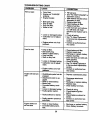
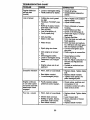
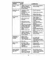
TROUBLESHOOTING
CHART
CORRECTION
PROBLEM
CAUSE
Will not start
• Out of fuel.
• Engine not =CHOKED"
properly.
• Engine flooded.
•
•
•
•
before
attempting to start.
Replace spark plug.
Clean/replace air filter.
Replace fuel filter.
Drain fuel tank and carbure-
•
•
•
•
•
•
•
•
•
•
Dirty air filter.
Bad spark plug.
Weak or dead battery.
Dirty fuel filter.
Stale or dirty fuel.
• Engine valves out of adjustment.
Clean/replace air filter.
Replace spark plug.
Recharge or replace battery.
Replace fuel filter.
Drain fuel tank and refill with
fresh gasoline.
• Check all wiring.
• See =To Adjust Carburetor"
in Service and Adjustments
section.
• Contact an authorized service center.
• Clutch/brake pedal not depressed.
• Attachment clutch is engaged.
. Weak or dead battery.
• Blown fuse.
• Corroded battery terminals.
• Loose or damaged wiring.
• Faulty ignition switch.
• Depress clutch/brake pedal.
• Faulty solenoid or starter,
• Check/replace solenoid or
starter.
• Contact an authorized service center.
• Faulty operator presence
switch(es).
Engine clicks but
will not start
in
• Engine valves out of adjustment.
• Loose or damaged wiring.
• Carburetor out of adjustment,
Engine will not tum
over
Operation section.
• Wait several minutes
tor, refill tank with fresh
gasoline and replace fuel filter.
• . Check all wiring.
• See "To Adjust Carburetor"
in Service and Adjustments
section.
• Contact an authorized service center.
• Loose or damaged wiring.
• Carburetor out of adjustment.
Hard to start
• Fill fuel tank.
• See "TO START ENGINE"
•
•
•
•
Bad spark plug.
Dirty air filter.
Dirty fuel filter.
Water in fuel.
•
• Weak or dead battery.
• Corroded battery terminals.
29
• Disengage attachment
clutch.
• Recharge or replace battery.
• Replace fuse.
• Clean battery terminals.
• Check all wiring.
• Check/replace ignition
switch.
• Recharge or replace battery.
• Clean battery terminals.
TROUBLESHOOTING CHART
PROBLEM
CAUSE
CORRECTION
i
Engine clicks but
will not start
(cont'd)
• Loose or damaged widng.
• Faulty solenoid or starter.
Loss of power
• Cutting too much grass/
too fast.
• Throttle in "CHOKE" position.
• Build-up of grass, leaves
and trash under mower.
• Dirty air filter.
• Low oil level/dirty oil.
• Faulty spark plug.
• Water in fuel.
fresh gasoline.
• Drain fuel tank and carbure-
• Spark plug wire loose.
tor, refill tank with fresh gasoline and replace fuel filter.
• Connect and tighten spark
• Worn, bent or loose blade.
• Bent blade mandrel.
• Loose/damaged part(s).
Poor cut - uneven
• Set in _Higher Cut" position/
reduce speed.
• Adjust throttle control.
• Dirty fuel filter,
• Stale or dirty fuel.
• Engine valves out of adjustment.
Engine continues
to run when operator leaves seat with
attachment clutch
engaged
• Check all wiring.
I • Check/replace solenoid or
starter.
• Clean underside of mower
housing.
• Clean/replace air filter.
• Check oil level/change oil.
• Clean and regap or change
spark plug.
• Replace fuel filter.
• Drain fuel tank and refill with
• Dirty engine air screen/
fins.
• Dirty/clogged muffler.
• Loose or damaged wiring.
• Carburetor out of adjustment.
Excessive vibration
ii
I. Faulty operator-safety
presence control system.
• Worn, bent or loose blade.
• Mower deck not level.
• Buildup of grass, leaves,
and trash under mower.
• Bent blade mandrel.
3O
j.
plug wire.
Clean engine air screen/fins.
• Clean/replace muffler.
• Check all wiring.
• See "To Adjust Carburetor" in
Service and Adjustments
section.
• Contact an authorized service center.
• Replac e blade. Tighten blade
bolt.
• Replace blade mandrel.
• Tighten loose part(s). Replace damaged parts.
• Check wiring, switches and
connections. If not
corrected, contact an authorized service center.
• Replace blade. Tighten blade
bolt.
• Level mower deck.
• Clean underside of mower
housing.
• Replace blade mandrel.
TROUBLESHOOTING
PROBLEM
CHART
CORRECTION
CAUSE
Poor cut - uneven
€ont'd)
• Clogged mower deck vent
holes from buildup of
grass, leaves, and trash
around mandrels.
• Clean around mandrels to
open vent holes.
Mower blades will
not rotate
• Obstruction in clutch
mechanism.
• Worn/damaged mower
drive belt.
• Frozen idler pulley.
• Frozen blade mandrel.
• Remove obstruction.
• Engine speed too slow.
• Place throttle control in
=FAST" position.
• Shift to slower speed.
• Allow grass to dry before
mowing.
• Level mower dect_
• Check tires for proper air
pressure.
• Replace/sharpen blade.
Tighten blade bolt.
• Clean underside of mower
housing.
• Replace mower drive belt.
• Reinstall blades sharp edge
down,
• Replace with blades listed in
this manual.
• Clean around mandrels to
open vent holes.
I Poor grass discharge
• Travel speed too fast.
• Wet grass.
• Mower deck not level.
• Low/uneven tire air pressure.
• Worn, bent or loose blade.
• Buildup of grass, leaves
and trash under mower.
• Mower drive belt worn.
• Blades improperly installed.
• Improper blades used.
• Clogged mower deck vent
holes from buildup of
grass, leaves, and trash
around mandrels.
Headlight(s) not
working (if so
equipped)
•
•
•
•
Switch is =OFP.
Bulb(s) burned out.
Faulty light switch.
Loose or damaged wiring.
• Blown fuse.
Battery will not
charge
Engine "backfires"
when turning engine "OFP
• Replace
mower drive belt.
• Replace idler pulley.
• Replace blade mandrel.
•
•
•
•
•
Turn switch =ON".
Replace bulb(s).
Check/replace light switch.
Check wiring and connections,
Replace fuse.
• Bad battery cell(s).
• Poor cable connections.
• Faulty regulator (if so
equipped).
• Faulty alternator.
• Replace battery.
• Check/clean all connections.
• Engine throttle control not
set at =SLOW"
position for 30 seconds
before stopping engine.
• Move throttle control to
=SLOW" position and allow
to idle for 30 seconds before
31
• Replace
regulator,
• Replace
_llternato,r.
stopping engine.
32
TRACTOR - - MODEL NUMBER 917.270814
SCHEMATIC
BATTERY
AMMETER
(OPTIONAL)
IGNYnON
SWITCH
I
L .........
I
GROUNDING
CONNECTOR
A
'v
(OPTIONAL)
eL_K
(_
IGNITIONuNIT _
1(2
SPARK
PLUGGAp
PLUGS ON
TWIN CYL, ENGINES)
NOTE
IGNITION SWITCH
YOUR TRACTOR IS
EQUIPPED WITH A SPECIAL
ALTERNATOR SYSTEM.
THE LIGHTS ARE NOT
CONNECTED TO THE
BATTERY, BUT HAVE THEIR
OWN ELECTRICAL SOURCE.
BECAUSE OF THIS, THE
BRIGHTNESS OF THE LIGHTS
WILL CHANGE WITH ENGINE
SPEED. AT IDLE THE LIGHTS
--e-WILL DIM. AS THE ENGINE IS
NON-REMOVABLE
SPEEDED UP, THE LIGHTS
CONNECTIONS
WILL BECOME THEIR BRIGHTEST.
HEADUGHTS
O
REMOVABLE
CONNECTIONS
WIRING INSULATED CLIPS
NOTE: IF WIRING INSULATED CLIPS WERE REMOVED FOR
SERVICING OF UNIT, THEY SHOULD BE REPLACED TO
PROPERLY SECURE YOUR WIRING.
33
F,
TRACTOR - - MODEL NUMBER 917.270814
ELECTRICAL
21
/
I
i
I
24_
41
I /
/!
8
34
, TRACTOR -- MODELNUMBER
917.2708i4
ELECTRICAL
KEY
PART
NO.
NO.
1
2
8
10
11
12
16
19
20
21
22
24
25
26
27
28
29
30
31
32
33
40
41
42
43
.44
45
52
55
70
163465
74760412
7603J
145211
150109
145769
153664
Std551125
73350400
166182
4152J
4799J
146148
166180
73510400
145491
121305X
140301
12421IX
141226
109310X
166145
71110408
131563
145673
73640400
121433X
141940
17490508
166658
DESCRIPTION
Battery 12 VOLT 28 AMP
BoltHex Hd 1/4-20unc x 3/4
Case Battery
Boit, Btr Front 1/4-20 x 7-1/2
Hoiddown Battery Front Mount
Nut, Push Nylon Battery Front 1/4
Switch, InterlockPush-In
Washer Lock 1/4
Nut Jam Hex 1/4-20 Unc
Harness L!ght Socket 0N/4152j)
Bulb Light #1156
Cable Battery
Cable Battery
Fuse 15 .amp
Nut Keps Hex 1/4-20 Unc
CId_le Ground
Switch Seat
Switch Ign 4 Position
Nut Ignition
Cover IgnitionSwitch
Key Molded Craftsman
Hamses Ign
Bolt BIk. Rn Hex 1/4-20 Unc x 1/2
Cover Terminal
Solenoid
Nut Keps BIk Hex 114-20 Unc
Ammeter Rectangular 6 Amp
ProtectionWire Loop
Screw'rbdroi 5/16-18 x 1/2
Harness Engine B&S
NOTE: All component dimensionsgive in U.S. inches
1 lbch = 25A mm
35
TRACTOR -- MODEL NUMBER 917.270814
CHASSISAND ENCLOSURES
28
58
12
63
31
55
14
36
TRACTOR - - MODEL NUMBER 917.270814
CHASSISAND ENCLOSURES
KEY
NO.
I
2
3
4
5
9
10
11
12
13
14
17
18
20
23
25
26
28
29
30
31
37
38
39
51
52
53
54
55
57
58
60
64
74
114
115
116
140
142
143
144
145
PART
NO.
166819
140356
17490612
STD551025
155272
161917X013
STD533710
155927
145660
155936
17490608
144983X558
126938X
156437
124028X
19131312
STD541437
145198)(558
155217X599
151287X558
139976
17490508
139886
139887
73800400
19091416
145201
161464
145202
STD522507
140547
STD533707
154798
STD541437
158112
17490620
19131614
158418
165867
154966
154207
156524
DESCRIPTION
Chassis Assembly
Drawbar
Screw, Thd. Roll 3/8-16 x 1
Washer 13/32 x 3/4 x 16 Gauge
Bumper Hood/Dash
Dash
Bolt, Carriage 3/8-16 x 1
Panel, Dash, LH.
Clip Tinnerman Grille p/t_
Panel, Dash, R.H.
ScrewThdrol 3/8-16 x 1/2
HoodAssembly
Bumper Hood
Plate Mtg Battery Fuel Tank
Bushing, Snap, Nylon, Fuel Line
Washer 13/32 x 13/16 x 12 Gauge
Locknut, Hax, with Insert 3/8-16 Unc
Gdlla w/Clips MS-558
Lens, Grille
Fend/Ftrest
Bracket, Fender Support
ScrewThdrol 5/16-18x 1/2
PivotBracket Assembly,L.H.
Pivot Brecht Assembly, R.H.
NUt Lock w/Insert 114-20 UNC
Washer 9/32 x 7/8 x 16 Ga.
BracketGrille PickoffLH
Screw Hex Wshd 8-16 x 7/8
Bracket Grille PickoffRH
Bolt, Fin Hex 114-20 UNC x .75
Air Duct P/L 18HP B&S Opp.Twin
Bolt Rdnd Sqnk 3/8-16 UNC x 3/4
Dash Lower STLT
Nut Cmwnlock 3/8-16 UNC
Keeper Belt Rear Lh Stl
Scrow Thrdel 3/8-16 x 1-1/4
Washer 13/32 x 1 x 14 Ga.
Bracket Suspension Front
Plate Reinfomement STLT
Bracket Swaybar Chassis
Bracket Pnt Footrest STLT
Rod Pivot Chassis/H(xxI
NOTE: All component dimensionsgive in U.S. inches
1 k_.,h= 25.4 mm
37
TRACTOR - - MODEL NUMBER 917.270814
GROUND DRIVE
197
61
4
32
170
,. 51
47
30
,, 151
2
62
37
26 27
38
TRACTOR-
- MODEL
NUMBER
917:270814
GROUND DRIVE
KEY
NO.
PART
NO.
1
........
2
3
4
5
6
146682
123666X
12000028
121520X
17490512
8
10
11
13
14
18
165866
STD561210
105701X
74550412
STD551125
STD523710
19
21
22
24
25
26
27
28
29
30
31
32
34
35
36
37
38
39
40
41
42
STD541437
106933X
130804
STD541237
106888X
STD551037
$3"D561210
145204
124236X
130807
127275X
STD523107
155071
120183X
BTD551062
STD571810
131494
STO523727
4470J
165838
19131312
47
48
49
50
51
52
53
65
56
127783
154407
123205X
STD523715
STD541437
STD541431
105710X
105709X
STD523712
'
DESCRIPTION
Transaxle (See Breakdown)
Peerless 206-545C
Spdng, Return, Brake
Putiey,Tmnsaxle
Ring, Retainer
Strap, Torque
Screw, Thd., Roll. 5/16-18 x 3/
4
Rod Shitter Fender STLT
Pin, Cotter 1/8 x 1
Washer, Shift Plate
Be_t 1/4-28 UNF W/Patch Gr. 8
Washer Lock 1/4
BoltFin Hex 3/8-16 UNC x 1.
Gr 5
Nut Lock Hex W/Ins.3/8-16
Knob
Rod, Brake
Nut Hex Jam 3/8-16
Spdng, Brake Rod
Washer 13/32 x 13/16 x 18 Ga.
Pin Cotter 1/8 x 3/4
Rod, Parldng Brake
Cap, ParkingBrake, Red
Bracket, Trar_saxle
Keeper, Belt, LH+
Bolt Flex lid. 5/16-18 x 3/4
Shaft Assembly,Foot Pedal
Boadng, Nylon
Washer 21/82 x 1 x16Ga.
Roll Pin 3/16 x 1"
Pulley, Idler, Rat
Bolt Fin Hex 3/18-16 x 2-3/4
Spacer, Split .395 x ,59
Keeper, Bolt, idler
Washer 13/32 x 13/16 x 12
Ga.
Pulley, Idler, V-Groove, Plastic
Bellcrank Clutch Grnd Dry Stl
Retainer, Belt
Bolt Hex Hd. 3/6-16 x 1-1/2
Nut Crown Lock 3/8-16 UNC
Nut Crown Lock 5/16-18 UNC
Unk, Clutch
Spring, Clutch Retum
Bolt Fin Hex 3/8-16 x 1-1/4
KEY
NO.
PART
NO.
57
58
59
61
62
63
64
130801
127274X
140312
17490612
8883R
140186
71170764
+ +
DESCRIPTION
V-Belt, Ground Drive
Keeper, Belt, R.H.
Keeper, Belt, Center Span
Screw, "Thd.,Rolt. 3/6-16 x 3/4
Cover, Pedal
Pulley, Engine
Bolt, Hex Heed, F{n.
7/16-20 x 4 Grade 5
65
STD551143
Washer Lock 7/16
66
154778
Keeper, Belt, Engine, FoolProof
70
134683
Guide, Mower Ddve Belt, R.H.
72
19132012
Washer 13/32 x 1-1/4 x 12 Ga.
74
137057
Spacer, Axle
75
121749X
Washer 25/32 x 1-1/4 x 16 Ga.
76
STD581075
E-Ring
77
123583X
Key, Square 2.0 x .1845/.1865
78
121748X
Washer 25/32 x 1-5/8 x 16
Gauge
79
STD580025
Key Woodruff
80
145090
Arm, Shift
81
165592
Shaft Assembly
82
165711
Spdng, Torsion
83
19171216
Washer 17/32 x 3/4 x 16 Ga.
84
166231
TransaxleLink
85
150360
Nut, Nylock
89
158391)(428
Conso|e, Shift, STLT
90
124346X
Nut, Selt-Thding,Wsh Hd 114
96
BTD624003
Retainer Spdng 1"
112
19091210
Washer 9/32 x3/4 x 10 Gauge
113
127285X
Strap Torque 90 Degrees
116
72110610
Bolt Rdhd Sqneck3/8-16 x 1.25
145
74490540
Bolt, He= Rghd 5/16-18 Gr. 5
150
165850
Bushing Bellcrank
151
19133210
Washer 13/32 x 2 x 10 Ge.
156
166002
Washer Brrtad 5/161D x 1.125
158
165589
Bracket Shift Mount
159
165494
Hub tapered Flange Shift
160
19292016
Washer 29/32 x 1-1/4 x 16 ga.
161
72140406
Bolt 1/4-20 3/4 gr.5
162
73680400
Nut Crownlock 1/4-20 Uoc
163
74780416
Belt Flex Fin 1/4-20
Lk_xl Gr5
164
-19091010
Washer 518x .281 x 10 Ga
165
165623
Bracket Pivot Lever
166
166880
Screw 5/16-18 x 5/8
168
165492
Bolt Shoulder 5/16-18 x .561
169
165580
Ptate Faster_ Cross
NOTE: All component dimensionsgive in U.S. inches
1 ioch= 25.4 mm
39
TRACTOR - - MODEL NUMBER 917.270814
STEERINGASSEMBLY
_41
$i
Sl_s4
47
13
u
40
16
40
/
TRACTOR
STEERING ASSEMBLY
KEY
NO.
1
2
3
4
5
6
7
8
9
10
11
13
15
17
18
19
22
23
25
26
27
28
29
30
32
36
37
38
39
40
41
42
43
44
46
47
51
54
62
63
65
66
67
68
79
80
- ,' MODEL
PART
NO.
139768
154427
156483
157473
6266H
121748X
19272016
12000029
3366R
156438
STD551137
154779
73901000
156546
57079
160395
165857
165851
154406
126847X
136874
19131416
17490612
STD561210
130465
155099
152927
139769
19133808
STD541537
100711L
145054
121749X
153720
121232X
6855M
STD541431
7478O520
167902
STD523710
154780
154404
74781044
154429
19132012
74950612
NUMBER
917,270814
DESCRIPTION
Steedng Wheel
Axle AssemblySTMP Dropped STL
Spindle Assembly,L.H.
Spindle Assembly,R.H.
Bearing, Race, Thrust, Hardened
Washer 25/32 x 1-5/8 x 16 Gauge
Washer 27/32 x 1-114x 16 Gauge
Ring; KIIp
Beerlng, steedng Column
Draglink Extended Stamped
Washer, Lock 3/8
Beadng Axle STLT/GT
Nut, Lock, Flange 5_-11 UNC
Shaft Assembly,Steering
Washer, Thrust .515 x .750 x .033
Support, Shaft
Screw Hex Wsh. Hd Ton(
Pittman Shaft Assembly
Bracket, Steedng
Bushing,Link, Drag
Gear, Sector
Washer 13/32 x 7/3 x 16 Gauge
Screw, Thd., Roll. 3/8-16 x 3/4
Pin Cotter 1/8 x 3/4
Rod, Tie
Bushing, Steering
Screw
Insert, Steering Wheel
Washer 13/32 x 2-3/8 x 8 Gauge
Nut Lock Center 3/8-24
Adaptor, Steedng Wheel
Boot, Steedng Shaft
Washer 25/32 x 1-1/4 x 16 Gauge
• ExtensionShaft steedng LR.LT
Cap, Spindle
Fitting, Grease
Nut Lock Hex w/Ins. 5/16-18 UNC
Bolt Fin Hex 5/16-18 UNC x 1-1/4
KitSteering Aem Service
Bolt, Rn Hex 3/8-16 UNC x 1 Gr 5
Spacer Axle
Bearing Arm PIttman
Bolt, Fin Hex 5/6.11 UNC x 2-3/4
Axle, Brace
Washer 13/32 x 1 1/4 x 12 Ga.
BoltHax Nylon 3/8-16 x 3/4
NOTE: Allcomponent dimensionsgiven in U.S. inches
1 inch= 25.4 mm
41
TRACTOR - - MODEL NUMBER 917.270814
ENGINE
15
38
14
13
32
31
39
29
\
OPTIONAL
EQUIPMENT
Spark Arrester
42
TRACTOR - - MODEL NUMBER 917.270814
ENGINE
KEY
NO.
PART
NO.
1
2
162152
17720410
3
......
4
5
6
7
8
10
11
12
13
14
15
16
17
23
25
26
27
29
31
32
33
34
35
37
149723
144069
144063
138129
150176
145552
STD551125
STD522507
165287
1328O336
13200300
STD551237
17490624
159880
145996
73920600
152927
137180
157103
161696
123487X
106082X
17490512
8543R
38
....
39
81
109227X
128861
=..
DESCRIPTION
Control,Throt Paddle 32 22
Screw, He_ Thd Cut 114-20 x 5i8
Engine, B&S, (See Breakdown) No. 461707-0145-E1
Muffler Exhaust
Exhauet _.sm. Le_
Exhaust Asm. Righl
Clamp Tube Double Engine
Bolt5/16-18unc x 3/4 W/Seres
Heat Shield Lt
Washer Lock Hvy.Helical 114
Bolt Rn He)( 1/4-20Unc x .75
Gasket, Muffler
Nipple, Pipe 4-1/2
Elbow, Standard 90°, 3/8-18 NPT
Washer Lock ExtTooth3/8
Screw Thdml 3/6.16x1-1/2 Tytt
Shlald, BnVDbr Guard
Control Choke
Nut Keps 3/8-24 Unf
ScrewTT #10-32 x 5 x 3/8 Flange
Arrestor,Spark
Tank, Fuel
Cap Fuel Guage
c_np, Hose
Spacer Pad
Screw Thdrol 5/16-18 x 3-4 Tyt
Line, Fuel
Plug, Oil Drain (Order From Engine Manufacturer)
Pad Idter
Nut Flange 1/4-20 Stmter Nut
NOTE: Allcomponent dimensionsgiven in U,S. inches
I Inch = 25.4 mm
43
TRACTOR - - MODEL NUMBER 917.270814
SEATASSEMBLY
KEY
NO.
1
2
3
4
5
6
7
8
9
10
11
12
PART
NO.
140123
140551
STD523710
19131610
145006
STD541437
124181X
17490616
19131614
155925
166369
166396
KEY
NO.
DESCRIPTION
Seat 3350 BIk/blkCraftsman
Bracket Pnt PivotSeat (folk)
Bolt Fin Hex 3/8-16uric X 1
Washer 13/32 X 3/4 X 10 Ga
Clip Push In Hinged
Nut Hex Lockw/ins 3/8-16 Unc
SpringSeat Cprsn 2 250 BIk Zi
ScrewThdrol 3/8-16 X 1 Ty-tt
Washer 13/32 X 1 X 14 Ga
Pan Pnt Seat (blk)
KnobSeat Adj.Wingnct
BracketPnt MountingSwitch
13
14
15
16
17
21
22
24
PART
NO.
121248X
72050412
134300
121250X
123976)(
153236
STD541431
19171912
DESCRIPTION
BushingSnap BIk Ny150 Id
BoltRdhd Sht Nk 1/4-20x1-1/2
Spacer Split28 X 86 Zinc
SpringCprsn 1 27 BIk Pnt
Nut Lock 1/4 Lge Fig Gr 5 Zinc
Bolt Shoulder5/16-18 Unc-2A
Nut Hex Lock w/Ins 5/16-18
Washer 17/'32X 1-3/16 X 12
Ga.
25
127016X
Bolt Shoulder5/16-18 X 62
NOTE: All component dimensions given in U.S.
inches1 inch = 25.4 mm
44
TRACTOR -- MODEL NUMBER 917.270814
DECALS
8
6
4
1
11
9
13
15'
KEY
NO.
PART
NO.
I
2
3
4
5
156439
165392
163200
163202
163207
6
7
133644
163259
5
KEY
NO.
DESCRIPTION
Decal, Fender Danger Sears
Decal, Engine B&S
Decal, Hood, R.H. Craftsman
Decal, Hood, L.H. Craftsman
Decal, Fender SD. WhL Rad/
6Sp 42"
Decal, Maintenance
Decal, Panel Dash B&S 19,5
Turbo
Decal Replacement SRS
Decal, Fender, Crsftsman Gold
167180
163204
=_
11
156368
13
15
19
20
22
------
146046
160396
138047
166887
149516
138311
154515
168779
172206
172207
KEY
NO.
WHEELS & TIRES
s,8
PART
NO.
PART
NO.
1
2
3
4
59192
65139
106222X
59904
5
6
106732X427
278H
7
90401"1
4,10
DESCRIPTION
Decal, Fender STL'r Oper Inst
E/S
Decal, V-Beit Dr Sch Tractor
Decal, Mower Drive Schematic
Decal, Battery Diehard Sears
Decal, Deck Mower EZ3
Decal, Battery
Oecat,Ult Hand_
Pad Footrest LH STLT
Pad Footrest RH STLT
Owner's Manual, English
Owners Manual, Spanish
DESCRIPTION
Valve Cap, Tire
Stem, Valve
Tire, Front
Tube, FrontTire
(Not Provided, Seneca Item
Only)
Rim, Front
Fitting,Grease(FrontWheel
Only)
11
Bearing,F_n_ (FrontWhe_
Only3
8
9
10
106108X427
122082X
7152J
Rim, Rear
Tire, Rear
Tube, Rear "rke
(No_Provided, Sen,tca Item
11
--
104757X
144334
Cep, A_de
Only)
Sealant, Tire 10 oz.
NOTE: All component dimensions given In U.S. Inches
1 Inch = 25A mm
45
TRACTOR
- - MODEL
NUMBER
917.270814
LIFT ASSEMBLY
27
5
/ /
/ /
/ i
49
/
/
3O
3
20
46
TRACTOR - - MODEL NUMBER 917.270814
LIFT ASSEMBLY
KEY
NO.
1
2
3
4
5
6
7
8
11
12
13
15
16
17
18
19
20
23
24
25
28
27
29
29
30
31
32
49
50
PART
NO.
159460
159471
105767X
12000002
19211621
120183X
125631X
122365)(
139865
139866
STD624008
127218
73350800
130171
73680800
139868
163552
110807X
19131016
2876H
76020308
126971X
73350600
138057
150233
140302
73540600
145212
110452X
DESCRIPTION
Lift Lever Inner Wire Assemio_y
Shaft Assembly, Lift
Pin, Groove
E-Ring
Washer 21/32 x 1 x 21 Gauge
Bearing, Nylon
Grip, Handle, Fluted
Button, Plunger, Red
Link, Lift, LH.
Link, _
R.H.
Retainer Spdng
Link, Front
Nut, Hex, Jam 1/2-13 UNC
Trunnion
Nut Lock 1/2-13 UNC
Arm, Suspension, Rear
Retainer Spdng
Nut, Special
Washer 13/32 x 5/8 x 16 Gauge
Spring
Pin, Cotter 3/32 x 1/2
Rod, Adjust, Lift
Nut, Hex, Jam 3/8-18 UNC
Knob, Inf. 3/8-16
Trunnion, Inf Height
Beadng, Pvt, Lift Special
Nut, Crownlock 3/8-24
Nut Flange Lock
Nut Push Phos & Oil
NOTE: All component dimensionsgiven in U.S. inches
I inch = 25.4 mm
47
TRACTOR
- - MODEL
NUMBER
917.270814
MOWER DECK
76
73
71
31
,_21
>21
21 22
4
\
6
21
48
TRACTOR - ' MODEL NUMBER 917,270814
MOWERDECK
KEY
NO.
1
2
3
4
5
6
8
9
10
11
12
13
14
15
16
17
18
19
20
21
22
23
24
25
26
27
28
29
30
31
32
33
34
35
36
37
40
41
43
44
45
46
48
49
50
51
52
53
54
55
56
PART
NO.
DESCRIPTION
Mower Deck Asseml_y,42"
Bolt Rdhd 5/16-18 x 3/4
Bracket Assembly,Sway Bar,
Front
138440
Bracket Assembly,Sway Bar
STD624008
Retainer Spdng
130832
Arm, Suspension,Rear
850857
Bolt, Hex 3/8-24 x 1.25
Grade 8
STD551137
Washer, Lock 3/8
140296
Washer, Hardened
134149
Blade, Mulching
129895
Bearing, Bali
137645
Shaft Assembly,Mandrel,
Vented (Includes Key
Number 12)
128774
Housing, MendreJI,Vented
110485X
Beadng, Ball, Mandrel
140329
Stripper,Vented Mower Deck
72110610
Bolt, Cardage 3/8-16 x 1-1/4
72140505
Bolt, Cardage 5/16-16 x 5/8
132827
Bolt. Shoulder
159770
Baffle, Vortex
STD541431
Nut Crownleck 5/16-18 UNC
134753
Stiffener Bracket
131267
Bracket, Deflector
105304X
Cap, Sleeve
123713X
Spdng, Torsion,Deflector
110452X
Hut, Push
130968
Shield, Deflen_r
19111016
Washer 11/32 x 5/8 x 16
Gauge
131491
Red, Hinge
157722
Screw Thdrol Washer Head
129963
Washer, Spacer
153535
Pulley,Mandrel
137266
Hut, Topiock, Flanged
STD533717
BoltRdhd 3/8-16 x 1-3/4
133835
Fastner, Chflstmas Tree
131494
Pulley, Idler, Rat
STD551G'37 Washer 13/32 x 13/16 x 16
Gauge
STD541437
Nut CrOwniock3/8-16 UNC
133551
Rod, Pivot,with Nibs
140083
Rod, CkJtch,Seconded/, with
Nibs
140088
Guard, Mandrel, L.H.
STD624003
Retainer Spdngl"
137729
Screw,Thd. RoKI 1/4-20 x 5/8
133944
Washer, Hardened
155066
RotterAssembly,Cam Folk_er
131340
Bolt, Shoulder #10-24 Grade 5
STD541410
Locknut #10-24
139888
Bolt, Shoulder 5/16-18 UNC
131845
Arm Assembly,Pad, Brake
133943
Washer, Hardened
155046
Ann, k:Uer
122052X
Spacer, Retainer
KEY
NO.
PART
NO.
58
59
67
68
71
72
73
74
140086
141043
162113
144200
142427
131870
127847
121748X
75
76
12000029
128903
164961
STD533107
138017
77
78
79
80
91
82
83
84
85
92
101
102
103
104
105
106
111
112
113
114
115
116
117
118
119
121
128
129
130
127845
160570
127498
153701
73350600
142028
120958X
156084
72140620
STD541437
136420
71161010
19061216
STD551110
160793
2029,,I
155197
155198
17490512
STD541431
72110504
4898H
165746
739306(X)
STD551037
143723
153390
19131312
STD523710
131
STD533710
132
19132203
141
--
6266H
130794
- -
164963
DESCRIPTION
Spring,TorsionBrakes
Guard, TUV Idler
Knob Custom Oval
V-Belt
Rod, Clutch, Primary, with Nibs
Spring, Return
Arm, Clutch, Secondary
Washer 25/32 x 1-5/8 x 16
Gauge
Ring, Klip
Bolt, Shoulder 3/8-16 UNC x
1.44
Keeper, Spring
LeverAsm. Clutch Pri PIm STLT
Bushing, Large, Brass
Spdng, Mower Clutch
Nut, Hex Jam 3/8-16 Unc
Trunnion,Adj.
Washer Sioterad
Keeper Belt Idler
Bolt Carriage 3,'8-16 x 2ol/2
Nut Lock 3/8-16
Mulcher Cover
Screw
Washer #10
Washer, Lock #10
Latch Assembly,Bagger
Nut, Weld
Bracket, Gauge, Wheel L.H.
Bracket, Gauge, Wheel R.H.
ScrewThdrol 5/16-18 x 3/4
NUt, Hex, Keps 5/16-18 UNC
Bolt, Carriage 5/16 UNC x 1/2
Bolt, Shoulder
Wheel, Gauge
Nut, Centarlock 3/8-16
Washer 3/8 x 7/8 x 14 Gauge
Bracket
Washer Felt
Washer 13/32 x 13/16 x 12 Ga.
Bolt, Fin Hex 3/8-16 UNC x 1
Gr. 5
BOY(,RDHD SQNK 3/8-16
UNC x 1
Spacer Washer
13/32 I.D. x 1-3/80.D. x 1/4
Washer Thrust .75 x 1.230
Mandrel Assembly (Includes
Key Numbera 8-10, 12-15, 31
and 32)
Mower Deck, Complete (Stan(lard Deck, Order Separately
Mulcher Plate and Gauge
Wheel Components, Key Nos.
101-106 and 111-121)
NOTE: All component dimensionsgiven in U.S,inshes
1 inch = 25.4 mm
49
TRACTOR
- - MODEL
PEERLESS TRANSAXLE-MODEL
NUMBER
917.270814
NUMBER 206-545C
Cw.-27
O.--29
150
8
706A
47
13
41A
5O
TRACTOR - - MODEL NUMBER 917.270814
PEERLESS TRANSAXLE-MODEL NUMBER 206-545C
KEY
PART
NO.
NO.
1
2
3
4
5
6
6A
7
8
8A
9
10
11
12
13
772147
780086A
770128
776395
776409
778364
778369
778330
792180
792047
784352
784378
778334
778309
778368
14
778368
15
17
18
20
21
22
25
25A
26
27
28
29
29A
29B
29<3
30
31
778370
786188
786102
792077A
792078
792079
792073A
792177
792125
792035
788040
780072
780160
780051
780199
780108
780001
31A
32
34
35
35A
36
37
38
39
40
780195
788083
780194
780193
780197
790075
790007
799021
786026
792076A
KEY
PART
DESCRIPTION
NO.
NO.
Tmnsaxle Cover
Need|e Bearing 5J8"
Transaxle Case
Countershaft
Output Shaft
Spur Gear (38 teeth)
Spur Gear (15 teeth)
Spur Gear (11 teeth)
Shift Key
Woodruff Key #9
Shift Collar
Shift Rod & Fork
Bevel Gear (30 teeth)
Input Bevel Pinion (13 teeth)
Bevet Gear (13 teeth) (include.
14)
Bevel Pinion (13 teeth) (Include. 13)
Ring Gear (43 teeth)
Drive Pin
Spacer 1.130 X .695
Ball 5/16` dia
Set Screw 3/8 - 16 x 3/8"
Spring .310 OD x .625 L
Screw 1/4 - 20 x 1-1/4*
Screw 1/4-20 x 1-3/8"
Retaining Ring (pkg of 2)
Rata'l_ng Ring
Retaining Ring
Thrust Washer .627 ID x .031W
Thrust Washer .762 ID x .031W
Thrust Washer .762 ID x .031W
Anti-RotationWasher .632
Cup Washer 1.127 ID x .032W
Flat Washer .750 ID x .056W
(Use As Needed)
Flat Washer .750 ID x .062W
Oil Seat 5/8"
Bushing .563
Flanged Bushing 5 / 8" ID
F_nged Bushing .751
Brake Disk
Brake Pad Plate
Brake Pad (pkg of 2)
Dowel Pin
Rat Washer .312 ID x ,059W
41A
42
42A
43
44
45
46
47
48
49
50
51
52
53
54
56
57
58
59
60
61
65
66
67
69
70
71
71B
76
77
79
82
790079
792073A
792086A
792075
790025
786066
786086
774690
774691
778356
778338
778354
778352
778350
778346
778355
778337
778353
776351
778349
776345
780189
776422
7763,96
792170
786187
788069
788092
780090
788078A
792144
778333
83
85
87
150
157
180
900
778338
792154
788069A
788093A
788088A
730229A
794712
DESCRIPTION
Brake Lever
Screw 1/4 - 20 x 1-1 14"
Screw 1/4 - 20 x 2 1/4"
Locknut5 / 16 - 24
Brake Pad Holder
Spacer .2625 x 1.0
Brake Lever Bracket
Axle (11-15 / 16" Long)
Axle (16 - 1/2" long)
Spur Gear (29 teeth)
Spur Gear (27 teeth)
Spur Gear (23 teeth)
Spur Gear (19 teeth)
Spur Gear (16 teeth)
Spur Gear (15 teeth)
Spur Gear (11 teeth)
Spur Gear (13 teeth)
Spur Gear (17 teeth)
Spur Gear (21 teeth)
Spur Gear (24 teeth)
Spur Gear (25 teeth)
F!at Washer .563 ID x .062W
Input Shaft
Shifter & Brake Shaft
Retaining Ring
Spaeer ,890
Square Cut Ring
"O" Ring
Flat Washer 1.128 ID x .058W
Inverted Retaining Ring
Spring .43OOD x .SO00L
Bevel & Spur Gear (30 & 13
teeth)
Spur Gear (27 teeth)
Oil Fdl Plug
Oil Seal 9/16`
Liquid Gasket RI"V Silicone
Oil Seal 3/4"
Gear Oil 80W90
Replacement MST - 206-545C
Transax|a
NOTE: All component dimensionsgiven in U.S. inches
1 inch= 25A mm
51
TRACTOR - - MODEL NUMBER 917.270814
BRIGGS& STRATTONENGINE-MODELNUMBER461707,TYPENUMBER0145-E1
52
TRACTOR - - MODEL NUMBER 917.270814
BRIGGS& STRATTONENGINE-MODELNUMBER461707,TYPENUMBER0145-E1
51 _
122
447
51A
861 PUMP REPAIR KIT
392• 402_ 306_-
i
425
968
121 CARBURETOR KIT
402_
3020
104_,
!97
I
102<_
643_
535
30a Y
14741
11:_8
_,,
I
1138
278o
592
"A"REQUIRESSPE_AL _LS
TO INSTALL.
INSTRUCTION
161
SEE REPAIR
MANUAL
_133
971
8ss
30_ 402_,_ _._
807 •
391
267
1036 LABEL
KIT-EMISSION
I
53
877
TRACTOR - - MODEL NUMBER 917.270814
BRIGGS& STRA'I-rONENGINE-MODELNUMBER461707,TYPENUMBER0145-EI
309]
5101
513
783 __
02
lO61
_
y
697 _#'
803
797 @
544'
801
358 GASKET
1770
51A__
634 _
569 _
54
7
SET
TRACTOR - - MODEL NUMBER 917.270814
BRIGGS & STRA'I-rONENGINE-MODEL NUMBER 461707, TYPE NUMBER 0145-E1
KEY PART
NO. NO.
1
2
3
4
5
5A
7
7A
8
9
10
10A
11
498583
399265
91086
493304
214517
214518
271867
271868
496754
27803
94382
94380
280225
273390
DESCRIPTION
Cylinder Assembly
Bushing/Seal Kit
'/r Seal-Oil
Sump-Eng_ne
Head-Cylinder #1
Head-CyUnder #12
*oGasket-Cylinder Head #1
*,Gasket-Cylinder Head #2
Breather Assembly (Cylinder # 1)
4r,Gasket-Breather
Scraw (Breather Assembly)
Screw (Breather Cover)
Tube-Breather
* Gasket-Crankcase
(.015" Thick, Std.)
271188
, Gasket-Crankcase (.005" Thick)
271189
, Gasket-Crankcase (.009" Thick)
13
94565
Screw (Cyllnder Head)
t5
94239
Plug-Oil Drain
16
690666
Crankshaft
19
399264
Bushing
20
291675
"t- Seat-Oit
23
491180
Flywheel
24
222699
Kay-Ft_eet
25
499180
Piston Assembly (Standard)
499181
Piston Assembly (.010 "O.S.)
499182
Piston Assembly (.020" O.S.)
499183
Piston Assembly (.030" O.S.)
26
499184
Ring Set, Piston (Standard)
499285
Ring Sat, Piston (.010 "O.S.)
499186
Ring Set, Piston (.020 "O.S.}
499187
Ring Set, Piston (.030 "O.S.)
27
263129
Lock-Piston Pin
28
498319
Pin Assembly, Piston (Std.!
498320
Pin Assembly-Piston (.005 O.S.)
29
498314
Rod-Connecting (Standard)
498541
Rod-Connecting (.020 U.S.)
32
95017
Screw (Connecting Rod)
33
390420
Valve-Exhaust (Include(a):
494553
Keeper-Valve (Rat. No. 42))
34
891302
Valve-Intake
35
65906
Spring-Valve (intake)
36
26828
Spring-Valve (Exhaust)
40
221596
Retainer-Valve (Exhaust)
41
292260
Retainer-Valve (Exhaust)
42
494553
Keeper-Valve
45
261368
Tappet-Valve
46
214487
Camshaft
47
393415
Stinger-Oil
48
498542
Short Block
50
213290
Manitold-intake
61
271412 *•Gasket-Intake
81A 270884
4r_l.Gaskst-lntake
53
93970
Screw (Carburetor)
54
93208
Screw (Intake Manifold)
73
691438
Screen-Rotating
75
222511
Washer (Flywheel)
78
691134
Screw (Flywheel Fan)
91
693483
Body Assembly-Upper
95
690718
Screw (Throttle Valve)
97
693465
Shaft-Throttle
98
807923
Kit-idle Speed
KEY PART
NO. NO.
102
104
105
107
108
109
117
693509
•
693506 Q
692078
•
693482
693505
693498
693538
693500
121 491539
122 281411
125 693479
130 693504
133 693512
146 94196
147 693508
161 496599
163 271411
*
177 271170
*
187 299146
197 96063
202 262683
203 280997
205 93971
209 262352
211 261563
212 693985
215 224816
219 394348
220 222773
222 491282
227 491297
235 224995
240 394358
244 230318
258 94930
267 93897
276 94942
297 94289
304 691390
308 690960
306 222846
306A 223734
307 94930
309 497596
310 94003
311 497608
332 230674
333 394891
334 94731
337 802592
356 494705
ir
•
,
+
DESCRIPTION
Gasket-Carburetor Body
P_n-P,oat H_nge
Valve-Float Needle
Body Assembly-Lower
Valve-Choke
Shaft-Choke
Jet-Main
Jet-Main (High Altitude)
Carburetor Kit
Spacer
Carburetor
Valve.Throttle
Float-Carburetor
Key-Timing
Jet-Pilot
Base-Air Cleaner
Gasket-AirCleaner
Seal-O-Ring
Line-Fuel (Cut to Required Length)
Screw (Back Ptata)
Link-Mechenical Governor
Crank-Ball
Screw (Bell Crank)
Spring-Governor
Spdng-Govemor
Link-Throttle
Guide-Air
Gear-Govemor
Washer-Throst (Governor Gear)
Bracket-Control
Lever-Governor
Shield-Fuel Spray
Filter-Fuel
Connector-Hose (Pulse Line)
Screw (Engine Sump)
Screw (Casing Clamp)
Washer (Governor Lever)
Nut-Wing _Air Fiite_ Retainer)
Housing-Blower
Screw (Blower Housing)
Shield-Cylinder
Shield-Cylinder
Screw (Cylinder Shield)
Motor-Starter
Bolt (Starter Motor)
Brush Set
Nut (Flywheel)
Armature-Magneto
Screw (Magneto Armature)
Plug-Spark
Wire-Stop
Included in Gasket Set, Ref Number 358.
Included in Carburetor Kit, Re| Number 121.
Included in Value Overhaul Kit, Rat Number
1095.
Included in Fuel Pump Kit, Ref Number 861
NOTE: All component dimensions given in U.S.
inches 1 inch = 25.4 mra
55
TRACTOR - - MODEL NUMBER 917.270814
BRIGGS& STRATTONENGINE-MODELNUMBER461707,TYPE NUMBER0145-E1
KEY
NO.
PART
NO.
358 495868
383 89838
386 693490
391 693487
392 693491
404 223882
423 94674
425 94823
432 693492
433 693489
434 693493
435 693494
441 222875
445 394019
447 93343
449 94882
474 93474
482 93621
510 497606
513 398003
523 494947
525 495348
527 223167
535 272490
544 97603
552 262332
552A 262331
562 93853
569 272645
572 222892
573 491304
592 92278
601 95162
615
94296
615A 93898
616 491530
634 491287
634A 271013
635 66538
637 693510
643 496700
689 262337
697. 93585
725 280866
726 91362
741 262989
783 693059
797 94010
797A 693167
801 394860
DESCRIPTION
Gasket Set
Wrench-Spark Plug
e+ Gasket-Pump
Body-Pump
e+ Spring-Pump Diaphragm
Washer (Governor Crank)
Screw (Air Cleaner Base)
Screw (Air Cleaner Cover)
e+ Cap-Spring
e+ Diaphragm-Fuel Pump
Cover-Diaphragm
Screw (Diaphragm Cover)
Bracket-Oil Flit
Filter-Air
Screw (Air Guide Cover)
Screw (oil Fill Bracket)
Altamator
Screw (Alternator)
Ddve-Starter
Clutch-Odve
Dipstick
Tube-Oil Fill
Clamp-Tube
Filter-Air
Armature-Starter
Bushing (Governor Crank)
Bushing (Governor Crank)
Bolt-Carriage (Governor Lever)
.A- Gasket-Baea
Cover-Breather (Cylinder #2)
Plate-Back
Nut (Govemor Lever)
Clamp-Hose
Retainer (Govemor Crank)
Retainer-Governor Shaft
Crank-Governor
tk Seal-Governor Shaft
Washer-Foam
Boot-Spark Plug
Washer-Seal
Retainer-Air Filter
Spdng-Fdction
Screw (Ddve Cap)
Shield-Heat
Gear-Ring
Gear-Th_ng
Gear-StaRer
Nut (StarterTerminal)
Nut (Starter Termlnel)
Cap-Ddve
KEY
NO.
PART
NO.
802
803
807
622
847
851
859
861
865
865A
868
868A
869
870
871
497607
497604
693511
693497
495715
493880
693488
393397
224774
224775
497656
273312
261463
262924
261961
231218
393456
495901
393815
877
881
918
934
955
968
971
1005
1006
1019
1036
1051
1058
1081
1090
1095
1125
1132
1136
1137
1138
---_r
•
•
+
DESCRIPTION
Cap-End
Housing-Starter
Spacer
Washer-Seal (Throttle Shaft)
Dipstick/TubeAssembly
Terminal-Cable
e+ Diaphragm-Fuel Pump
Kit-Fuel Pump
Cover-Air Guide
Cover-Air Guide
Seal-Valve
Seal-Valve
Seat-Valve (intake)
Seat-Valve (Exhaust)
Bushing-Guide (Exhaust)
Bushing-Guide (Intake)
Wire-Aitemator
Plate-Cover
Hose-Vacuum (Cylinder-Totrnpu|se Pump)(Cut to Require
Length)
94627
Screw (Fan Retainer)
693513
Plug-Carburetor
225008
Cover-Air Cleaner
805540
Screw (Upper Body To Lower
Body)
498157
Fan-Flywheel
224901
Retainer-Fan
496726
Label Kit
499382
Label Kit-Emission
263080
Ring-Retaining
273688
Owne¢s Manual
280860
_r Seal-O-Ring
497605
Retainer-Brush
498047
Gasket Set-Valve Overhaul
94724
S_ew (Cover Plate)
94675
Screw (Oil Slinger)
94297
Screw (Governor, Control Roc
220680
Washer (Governor, Control
Rod)
94298
Nut (Governor, Control Rod
460707-0145-EIRep_oamant Engk_e
Included in Gasket Set, Ref Number 358.
Included in Carburetor Kit, Ref Number 121.
Included In Value Ovethaut Kit, Ref Number
1095.
Included in Fuel Pump Kit, Ref Number 861
NOTE: All component dimensionsgiven in U.S.
inches I inch = 25.4 ram
56
57
58
SUGGESTED
GUIDE FOR SIGHTING SLOPES FOR SAFE OPERATION
ONLY RIDE UP AND DOWN HILL,
NOT ACROSS HILL
SIGHTING
GUIDE
O1
(D
15° MAX.
I
I_
I
greater than 15°), never across the face. Make turns gredually to prevent tipping or loss of control. Exercise extreme
Operate when
caution
your Tractor
changingupdirection
and downonthe
slopes.
face of slopes (not I
For in-home major brand repair service:
Call 24 hours a day, 7 days a week
1-800-4-MY-HOME
=' (1-800-469-4663)
Para pedir servicio de reparaci6n a domicilio
1-800-676-5811
In Canada for all your service and parts needs call
Au Canada pour tout le service ou les pibces
1-800-665-4455
For the repair or replacement parts you need:
Call 6 am - 11 pm CST, 7 days a week
PartsDirect s"
1-800-366-PART
(1-800-366-7278)
Para ordenar piezas con entrega a domiciUo
1-600-659-7084
For the location of a Sears Parts and Repair Center
in your area:
Call 24 hours a day, 7 days a week
1-800-488-1222
For information on purchasing a Sears Maintenance
•Agreement or to inquire about an existing Agreement:
Call 9 am - 5 pm, Monday - Saturday
1-800-627-6655
172206
10.28.99
RD
Pdntad in U.S.A.