1
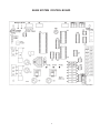
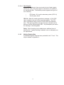
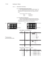
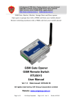
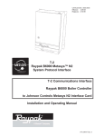
CATALOG NO.: 5000.59A Effective Date: 3-15-99 Replaces: 3-01-98 T-3 Raypak B6000 Modbus System Protocol Interface T-3 Communications Interface Raypak B6000 Boiler Controller to Modbus Interface Card Installation and Operating Manual 1 240729 TABLE OF CONTENTS 1.0 Contents (as shipped) ---------------------------------------------------------------------------------- 3 2.0 Forward ----------------------------------------------------------------------------------------------------- 3 3.0 Installation and Mounting ------------------------------------------------------------------------------ 4 3.1 Dimensions and Weight ------------------------------------------------------------------------ 4 3.2 Mechanical Installation -------------------------------------------------------------------------- 4 3.3 Electrical Installation ----------------------------------------------------------------------------- 4 4.0 Wiring ------------------------------------------------------------------------------------------------------- 5 5.0 B6000 System Control Board ------------------------------------------------------------------------- 6 6.0 Wiring: ------------------------------------------------------------------------------------------------------ 7 7.0 Wiring: B6000 System Control to T-3 Cable ----------------------------------------------------- 7 8.0 Check Your Power to T-3 ------------------------------------------------------------------------------ 7 9.0 Modification ------------------------------------------------------------------------------------------------ 8 ProSoft T-3 Raypak B6000 Modbus Protocol Interface -------------------------------------------- 9 11.0 ProSoft T-3 Card---------------------------------------------------------------------------------------- 9 11.1.0 ProSoft Product Specifications ----------------------------------------------------------- 10 11.2.0 Slave Port Functionality -------------------------------------------------------------------- 11 11.2.1.0 MODBUS Communications ----------------------------------------------------- 11 11.2.1.1 Command/Relpy Cycle ----------------------------------------------- 11 11.2.1.2 Command Types ------------------------------------------------------- 11 11.2.1.3 Command Error Checking ------------------------------------------- 11 11.2.1.4 Data Integrity ------------------------------------------------------------ 12 11.2.2.0 Modbus Register Map ------------------------------------------------------------ 12 11.3.0 Hardware Setup ------------------------------------------------------------------------------ 13 11.3.1.0 1500 Card Setup ------------------------------------------------------------------- 13 11.3.1.1 Connecting Power to the T-3 Card -------------------------------- 13 11.3.1.2 Dip Switch Configuration --------------------------------------------- 13 11.3.1.3 Jumper Configurations ----------------------------------------------- 15 11.3.2.0 B6000 Communications ---------------------------------------------------------- 15 11.4.0 Modbus Protocol Support ------------------------------------------------------------------ 16 11.4.1 Modbus Commands ----------------------------------------------------------------- 16 11.5.0 Diagnostics ------------------------------------------------------------------------------------- 17 11.5.1 LED Indicators ------------------------------------------------------------------------- 17 11.6.0 ProSoft Support, Service and Warranty ----------------------------------------------- 18 11.6.1.0 Technical Support ------------------------------------------------------------------ 18 11.6.2.0 Service and Repair ---------------------------------------------------------------- 18 12.0 Raypak Limited Warranty ---------------------------------------------------------------------------- 19 APPENDICES Appendix A T-3 Modbus Register Map Appendix B Port 1 : Modbus Slave Port RS-485 Cable Port 2 : B6000 Burner Controller RS-485 Cable 2 T-3 (Raypak B6000 System Protocol Interface) Contents Quantity FLOPPY DISK 3.5” T-3 EPROM (CPX.XNMn) in small black ESD box 1 1 1 Check packaging for damage or missing components. IMPORTANT NOTICE: These instructions are intended for the use by qualified personnel only, specifically trained and experienced in the installation of this type of equipment and related system components. Installation and service personnel may be required by some states to be licensed. If your state is such, be sure your contractor bears the appropriate license. Only qualified persons shall attempt to repair this equipment. Repair must be according to these instructions. WARNING: Improper installation, adjustment, alteration, service or maintenance may damage the equipment, create a hazard resulting in asphyxiation, explosion, fire electric shock, personal injury or property damage and will void the warranty. CAUTION: ONE SUPPLY SOURCE. TO REDUCE THE RISK OF ELECTRIC SHOCK, DISCONNECT ALL CONNECTIONS BEFORE SERVICING. CAUTION: RISK OF ELECTRIC SHOCK, DISCONNECT SWITCH IS REQUIRED TO DE-ENERGIZE THE EQUIPMENT BEFORE SERVICING. Thank you for selecting the Raypak B6000 Boiler Management System and the Raypak Communication Interface. It is our sincere hope that you will enjoy its power, ease of use and energy saving features. Please follow the instructions carefully to insure proper installation. FORWARD The Raypak Communication Interface is designed to allow the Communication Interface System to monitor and control the Raypak B6000 Boiler Management System. 3 T-3 INSTALLATION AND MOUNTING The T-3 Module should be mounted on a permanent base not subject to vibrations, moisture or dust. It should be readily accessible, for serviceability. DIMENSIONS AND WEIGHT 15 3/4” H 8” W 5 3/4” D 14 LBS MECHANICAL INSTALLATION Mount the System Protocol Interface within five (5) feet of B6000 System Control Box. The Gateway enclosure must be mounted vertically with conduit holes facing downward. Conduit holes are provided to accommodate standard conduit fittings. Additional or larger conduit fittings that may be required should be located on the bottom of the module. Mount the Interface with 3/8” or 1/4” hardware in four (4) places. A Minimum of six (6) inches clearance on all sides is required and a minimum of eighteen (18) inches clearance from the front is required for service access. The hinged side of the box is to the right and the clearance (minimum 3” from bolt hole on the right side) should be sufficient to open the cover. A sub-panel containing the disconnect switches and surge suppressors is required at or near the equipment location(s). For accessibility remove the lower interior panel, by removing the four (4) access screws. INSTALL CONDUIT AS APPROPRIATE. ELECTRICAL CHARACTERISTICS 120 VAC, 0.25A, 60 Hz ELECTRICAL INSTALLATION 115 VAC FEEDER CIRCUITS Install a surge protection device sized appropriately for your installation. Install separate disconnect means for each load. Pull in appropriately sized wire for equipment as defined by NEC and/or local code. All primary wiring will be 125% of minimum or maximum rating. It is strongly recommended that the Communications Interface, B6000 System Control Module and the B6000 Boiler Control Module be supplied from the same source power. 4 WIRING T-3 1. Turn off power to the B6000 System Control Box. 2. Open front door of System Protocol Interface Gateway Enclosure. 3. Remove four screws and the lower cover, revealing the field wiring blocks. 4. Attach wires from interface card to the field wiring side of left terminal block (N+, N-, GND, NC). Refer to diagram in this user manual. 5. Open front door of the B6000 System Control Box. 6. Remove four screws and the lower cover, revealing the field wiring blocks in lower left. 7. Run RS-485 cable (provided) to the lower left field wiring terminal in the B6000 System Control box. Attach wires to the upper four terminals as follows: BLU/WHT WHT/BLU ORG/WHT SHIELD to to to to + COM GND (1) (2) (3) (4) 8. The EPROM (CPX.XNMn), in small black ESD box, must be installed in place of the current EPROM. 9. View the B6000 System Control Board picture on the next page. Note location of EPROM, U4. 10. Remove four screws holding upper panel with display screen and keypad. Carefully remove upper panel and turn over exposing B6000 System Control Board, (see next page). 11. Using ESD procedures carefully remove the EPROM from location U4. 12. Again using ESD procedures carefully install the EPROM labeled CPXXNM or CPXXM into location U4. 13. Re-assemble B6000 System Control Box. 14. Turn power on to B6000 System Control Box. 15. Connect 120 VAC (hot, Neutral, ground) to T-3 at right terminal block. 16. Re-assemble. 5 B6000 SYSTEM CONTROL BOARD Fig. # 9460 6 CHECK YOUR POWER SOURCE CB VOM WHITE GROUND PIDOMA BLACK A GREEN B C AC = 108 Volts AC Minimum, 132 Volts MAX AB = 108 Volts AC Minimum, 132 Volts MAX BC = Must be less than 1.0 Volts AC 7 8 11.0. T-3 Revision 1.0 Raypak B6000 Modbus Protocol Interface Please Read this Notice Successful application of the T-3 card requires a reasonable working knowledge of the Raypak B6000 Boiler Control, and the application in which the combination is to be used. For this reason, it is important that those responsible for implementing the T-3 satisfy themselves that the T-3 and B6000 Boiler Control combination will meet the needs of the application. This manual is provided to assist the user. Every attempt has been made to assure that the information provided is accurate and a true reflection of the product’s installation requirements. In order to assure a complete understanding of the operation of the T-3 with B6000 Controller, the user should read all applicable Raypak documentation on the operation of the B6000. 1234567890123456789012345678901212345678901234567890123456789012123456789012345678901234567890121234 1234567890123456789012345678901212345678901234567890123456789012123456789012345678901234567890121234 1234567890123456789012345678901212345678901234567890123456789012123456789012345678901234567890121234 1234567890123456789012345678901212345678901234567890123456789012123456789012345678901234567890121234 1234567890123456789012345678901212345678901234567890123456789012123456789012345678901234567890121234 1234567890123456789012345678901212345678901234567890123456789012123456789012345678901234567890121234 1234567890123456789012345678901212345678901234567890123456789012123456789012345678901234567890121234 1234567890123456789012345678901212345678901234567890123456789012123456789012345678901234567890121234 1234567890123456789012345678901212345678901234567890123456789012123456789012345678901234567890121234 1234567890123456789012345678901212345678901234567890123456789012123456789012345678901234567890121234 1234567890123456789012345678901212345678901234567890123456789012123456789012345678901234567890121234 1234567890123456789012345678901212345678901234567890123456789012123456789012345678901234567890121234 1234567890123456789012345678901212345678901234567890123456789012123456789012345678901234567890121234 1234567890123456789012345678901212345678901234567890123456789012123456789012345678901234567890121234 1234567890123456789012345678901212345678901234567890123456789012123456789012345678901234567890121234 1234567890123456789012345678901212345678901234567890123456789012123456789012345678901234567890121234 1234567890123456789012345678901212345678901234567890123456789012123456789012345678901234567890121234 1234567890123456789012345678901212345678901234567890123456789012123456789012345678901234567890121234 1234567890123456789012345678901212345678901234567890123456789012123456789012345678901234567890121234 1234567890123456789012345678901212345678901234567890123456789012123456789012345678901234567890121234 1234567890123456789012345678901212345678901234567890123456789012123456789012345678901234567890121234 1234567890123456789012345678901212345678901234567890123456789012123456789012345678901234567890121234 1234567890123456789012345678901212345678901234567890123456789012123456789012345678901234567890121234 1234567890123456789012345678901212345678901234567890123456789012123456789012345678901234567890121234 1234567890123456789012345678901212345678901234567890123456789012123456789012345678901234567890121234 1234567890123456789012345678901212345678901234567890123456789012123456789012345678901234567890121234 1234567890123456789012345678901212345678901234567890123456789012123456789012345678901234567890121234 WARNING The T-3 card will allow remote access to commands in the B6000 Controller. The User is responsible for assuring that any applicable regulations concerning the remote operation of equipment are adhered to. 9 11.1. Product Specifications The T-3 card is a hardware product designed to be the communications front end for the Raypak B6000 Boiler Control and a modbus Master Host. The product includes the following functionality: Modbus Slave Specifications • Protocol Modes: RTU mode with CRC-16 error checking • Supported Modbus Function codes: 2 Read Input Status 3 Read Multiple Data Registers 4 Read Input Registers 6 Preset (Write) Single Data Register 8 Loopback Test (Test 0 only) • Supports broadcast commands from host • RS-485 electrical interface Raypak B6000 Interface • RS-485 electrical interface • Emulates Raypak Modem address and functionality General Specifications • Configurations via dip switches Slave Address, Baud and Parity Hardware Specifications • 4X5” form factor • Two male 9-pin D Shall connectors • Communications Status lights - Active and Fault for each port • 9 to 30 VDC external power 10 Slave Port Functionality 11.2.0 11.2.1 Modbus Communications The T-3 Modbus Slave card runs the RTU version of the Modbus protocol. This capability allows the module to communicate data from a Raypak B6000 Boiler Control to a Modbus Master host, and vice-versa. The module supports both point-to-point implementation as well as multi-drop implementations. The following discusses the functional capabilities of the T-3 card. 11.2.1.1 Command/Reply Cycle Successful communications between the card and a host will always consist of the following two transactions: Command: Message from master giving instruction to slave. Reply: Response to command. A slave station will respond to a master issued command in several ways. Data Message: If the command was executed by the T-3 board, the response message will include the data requested, or an acknowledgement that the command was executed. Error Message: If the command could not be executed by the T-3 board, for whatever reason, an error response message is transmitted to the master. The error response message consists of the original function code (ORed with 80hex) and error code. No Reply: If the master does not detect a reply within its time-out period, the master should retransmit the command, before a time out error is issued. If the Slave could not decode the message or an error occurred preventing the Slave from recognizing the message, no response will be issued. 11.2.1.2 11.2.1.3 Command Types The T-3 can respond to three types of commands from the master; read data, write data, and a diagnostic command. These are overviewed below: Read Data: 2 3 4 The following type of data read commands are supported: Read Input Status Read Multiple Registers Read Input Registers Write Data: 6 The Following data write command is supported: Single Register Write Diagnostics: 8 The diagnostic command is supported: Loopback test - Code 0 Command Error Checking When the T-3 cannot execute a command, an error code is generated and returned to the master. Error codes generated at the slave will usually be indicative of an illegal function, an illegal address, bad data, or the inability to complete a transaction because of a network problem. 11 11.2.1.4 Data Integrity As in all good protocols, there must exist a level of data integrity checking to verify, with some degree of assurance, the quality of the transmitted data. The Modbus protocol supports two types of error checking: • • RTU Mode: 16 bit cyclic redundancy check (CRC-16) One bit parity check CRC-16: When the master generates a message, a 16 bit CRC value is added to the end of the transmitted packet. The CRC value is generated using a series of the bit shifts and manipula tions. The receiving station executes the same calculation of the data and verifies the transmitted CRC. Any discrepancy will cause the message to be disregarded. Parity: Parity checking can be added as an additional level of data security. If parity checking is selected, even or odd parity can be implemented. 11.2.2 Modbus Register Map A predefined register map has been provided for the T-3 unit. This map is detailed in Appendix A. 12 Hardware Setup 11.3.0 11.3.1.1 1500 Interface Card Setup 11.3.1.1 Connecting Power to the T-3 Card The T-3 Card requires an external source of DC voltage. The DC source voltage should be between 9V and 30V. The power is connected to TB1, located near the two 9 pin serial port connections. The connection to TB1 is as follows: TB1-1 9-30 VDC (+) TB1-2 Common (-) 11.3.1.2 Dip Switch Configuration The T-3 card is configured primarily through two sets of dip switches. These switches are read initially on power up only. The function of the dip switches is as follows (a value of one (1) is registered when the a switch is in the ON position): SW 1 1 2 3 4 5 6 7 8 O F F ↓ • • OFF Position: SW 2 • • • • • • O F F ↓ ON Position: 1 2 3 4 5 6 7 8 • OFF Position: • • • • • • • ON Position: SW1 : Modbus Port Configuration Switch Position 1 2 3 * Function Baud Rate Selection Factory Settings 9600, No Parity, Address Bit 1 4 5 Parity Selection 6 7 8 3 0 0 0 0 1 1 1 1 2 0 0 1 1 0 0 1 1 5 0 0 1 1 4 0 1 0 1 Positions 1 0 300 1 600 0 1200 1 2400 0 4800 1 9600 0 19200 1 19200 None Odd Even Invalid * * Not Used SW2 : Modbus Slave Address Configuration Switch Position 1 2 3 4 5 6 7 8 Function Baud Rate Address Select 13 1 2 3 4 5 6 7 8 Positions Address Bit Address Bit Address Bit Address Bit Address Bit Address Bit Address Bit Address Bit 0 1 2 3 4 5 6 7 Value = 1 Value = 2 Value = 4 Value = 8 Value = 16 Value = 32 Value = 64 Value = 128 * Example Addresses = 0 to 33 8 7 6 5 4 3 0 0 0 0 0 0 0 0 0 0 0 0 0 0 0 0 0 0 0 0 0 0 0 0 0 0 0 0 0 1 0 0 0 0 0 1 0 0 0 0 0 1 0 0 0 0 0 1 0 0 0 0 1 0 0 0 0 0 1 0 0 0 0 0 1 0 0 0 0 0 0 0 0 0 0 0 1 1 0 0 0 0 1 1 0 0 0 0 1 1 0 0 0 0 1 1 0 0 0 1 0 0 0 0 0 1 0 0 0 0 0 1 0 0 0 0 0 1 0 0 0 0 0 1 0 1 0 0 0 1 0 1 0 0 0 1 0 1 0 0 0 1 0 1 0 0 0 1 1 0 0 0 0 1 1 0 0 0 0 1 1 0 0 0 0 1 1 0 0 0 0 1 1 1 0 0 0 1 1 1 0 0 0 1 1 1 0 0 0 1 1 1 0 0 1 0 0 0 0 0 1 0 0 0 2 0 0 1 1 0 0 1 1 0 0 1 1 0 0 1 1 0 0 1 1 0 0 1 1 0 0 1 1 0 0 1 1 0 0 1 0 1 0 1 0 1 0 1 0 1 0 1 0 1 0 1 0 1 0 1 0 1 0 1 0 1 0 1 0 1 0 1 0 1 Example Addresses = 34 to 63 8 7 6 5 4 3 2 0 0 1 0 0 0 1 0 0 1 0 0 0 1 0 0 1 0 0 1 0 0 0 1 0 0 1 0 0 0 1 0 0 1 1 0 0 1 0 0 1 1 0 0 1 0 1 0 0 0 0 1 0 1 0 0 0 0 1 0 1 0 1 0 0 1 0 1 0 1 0 0 1 0 1 1 0 0 0 1 0 1 1 0 0 0 1 0 1 1 1 0 0 1 0 1 1 1 0 0 1 1 0 0 0 0 0 1 1 0 0 0 0 0 1 1 0 0 1 0 0 1 1 0 0 1 0 0 1 1 0 1 0 0 0 1 1 0 1 0 0 0 1 1 0 1 1 0 0 1 1 0 1 1 0 0 1 1 1 0 0 0 0 1 1 1 0 0 0 0 1 1 1 0 1 0 0 1 1 1 0 1 0 0 1 1 1 1 0 0 0 1 1 1 1 0 0 0 1 1 1 1 1 0 0 1 1 1 1 1 Address Invalid 1 * 2 3 4 5 6 7 8 9 10 11 12 13 14 15 16 17 18 19 20 21 22 23 24 25 26 27 28 29 30 31 32 33 * Indicates Factory Setting 14 1 0 1 0 1 0 1 0 1 0 1 0 1 0 1 0 1 0 1 0 1 0 1 0 1 0 1 0 1 0 1 Address 34 35 36 37 38 39 40 41 42 43 44 45 46 47 48 49 50 51 52 53 54 55 56 57 58 59 60 61 62 63 The parameters are defined as follows: Modbus Slave Address: Each of the separate drop offs of a Modbus host must have a different slave address. The slave address is selected by encoding the slave address in a binary form using the dip switches. 11.3.1.3 T-3 Jumper Configurations The T-3 card has five sets of jumpers on the board. Generally, the default jumper positions will be adequate for most applications, with JP4 and JP5 being the only jumpers that should ever need to be reviewed. For completeness, we provide the following discussion on all the jumper locations: Jumper JP1 JP2 JP3 JP4 JP5 11.3.2 Description Hardware Reset Raypak Port Power (P2) Raypak Port Ground (P2) Modbus Port (P1) Termination Resistor Modbus Port (P1) RS-232 or RS-422/485 Select Positioning Default Not Used 1-2 Non-Isolated Power 1-2 2-3 Isolated Power 1-2 Non-Isolated Power 1-2 2-3 Isolated Power 1-2 Connect 120 ohms on 2-3 Rx lines (multidrop only) 2-3 Disconnect 120 ohms 1-2 RS-232 Select 2-3 2-3 RS-422/485 Select B6000 Communications The B6000 communications interface has been hard coded (i.e., no dip switches are required to configure this port) to operate at the following default conditions: Baud Parity Stop Bits 9600 None 2 The T-3 card emulates the modem card that is normally connected to the B6000 Controller. 15 11.4.0 Modbus Protocol Support 11.4.1 Modbus Commands The T-3 card supports a command subset of the Modbus Specification consisting primarily of the Function Codes required to read and write data. The following sections detail the different commands supported by the card. Function Code 11.4.2 Address Command Slave Driver Range 2 Read Input Status 10001 to 10331 & 10833 3 Read Multiple Registers 40001 to 40138 The Module returns word data from the register space. The module will support up to 125 words of data in one command. 4 Read Input Registers 30001 to 30138 The module returns data from the “Input register” space in the module. The module will support up to 125 words of data in one command. 6 Single Register Write 8 Loopback Test 40001 to 40030 and 40133 to 40138 Test 0 Comments Module returns binary data from the “Input Status” register space. This is a register write command allowing a host to change values in the B6000 unit by writing a register value. This is a diagnostic command which echoes the command sent. Modbus Error Codes The T-3 card supports the following Modbus Error Codes: Code 0 1 2 Name All OK Illegal Functions Bad Data Address 3 Bad Data Value 4 Incomplete Response Detected 6 Module Busy Description The module is operating as desired An illegal function code request is being attempted The address, or the range of addresses, covered by a request from the master are not within allowed limits. The value in the data field of the command is not allowed. This error indicates that an incomplete response was received to a master query. Often this will indicate that the slave device may be responding too quickly or that there may be excessive noise on the line. The module busy status code is returned when a write command from the master has not yet been completed when a second write command is received 16 11.5.0 Diagnostics Several hardware diagnostics capabilities have been implemented using the LED indicator lights on the front of the T-3 card. The possible conditions as indicated by the lights are: 11.5.1 LED Indicators Several hardware diagnostics capabilities have been implemented using the LED indicator lights on the front of the module. The possible conditions as indicated by the lights are: Name Modbus (P1) ACTIVE LED D1 Color Green Status Blinking Steady ON or OFF Raypak (P2) ACTIVE D2 Green Modbus (P1) COMM ERR D3 Red Raypak (P2) FAULT D4 Red Blinking Steady ON or OFF ON or Blinking OFF ON OFF Indication The T-3 is receiving a command from the Modbus Host The T-3 is not detecting a valid command. If the master is transmitting, be sure all dip switches are set correctly and that the cable connection is correct. The T-3 is processing a B6000 command Check cable connection to verify polarity of terminations between T-3 card and B6000 (See Appendix B) The Modbus port has detected a communications error condition. See Section 4.2 No error conditions at this time. The T-3 card has detected a communications error condition. No error conditions at this time. Should the configuration dip switches select an invalid address or an invalid baud rate, the LED indicators will alternate in the on/off fashion on 1/2 second intervals until correct values are selected. 17 11.6.0 ProSoft Support, Service and Warranty 11.6.1 Technical Support ProSoft Technology survives on its ability to provide meaningful support to its customers. Should any questions or problems arise, please feel free to contact us at: ProSoft Technology, Inc. 9801 Camino Media Suite 105 Bakersfield, CA 93311 (805) 664-7208 (805) 664-7233 FAX Before calling for support, please prepare yourself for the call. In order to provide the best and quickest support possible, we will most likely ask for the following information (you may wish to fax it to us prior to calling): 1. Product Serial and Version Number 2. T-3 Configuration Information - Dip Switches - Jumpers - Communication cabling 11.6.2 Service and Repair The T-3 card is an electronic product, designed and manufactured to function under somewhat adverse conditions. As with any product, through age, misapplication, or any one of many possible problems, the card may require repair. The T-3 product has a one year parts and labor warranty according to the limits specified in the warranty. Replacement and/or returns should be directed to the distributor or Original Equipment Manufacturer from whom the product was purchased. If you need to return the card for repair, if is first necessary to obtain an RMA number from ProSoft Technology. Please call the factory for this number and display the number prominently on the outside of the shipping carton used to return the card. 18 LIMITED WARRANTY T-3 SCOPE OF WARRANTY: Raypak, Inc. (“Raypak”) warrants to the original owner the T-3 to be free from defects in materials and workmanship under normal use and service for the applicable warranty period. In accordance with the terms of this Limited Warranty, RAYPAK will furnish a replacement or repair, at our option, any defective part which fails in normal use and service during the applicable warranty period. The replacement or repair will be warranted for only the unexpired portion of the original Warranty Period. APPLICABLE WARRANTY PERIOD The effective date of warranty coverage is the date of original installation, of the Control System, by a qualified electrician or by a RAYPAK authorized service technician. The Applicable Warranty Period is one (1) year form the effective date. WARRANTY EXCLUSIONS This Limited Warranty does not apply: 1. if the control system is not properly installed by a qualified technician in accordance with manufacture’s installation instructions, applicable codes, ordinances and good trade practices, 2. to damage or malfunctions resulting from failure to properly install, operate or maintain the system in accordance with the manufacture’s instructions; 3. if the rating plate’(s) or serial number(s) are altered, defaced or removed; 4. if the System is modified in any way or used with any non-factory authorized accessories or components; 5. to damage or failure from abuse, accident act of nature, fire, flood, freezing or the like; 6. to accessories, rubber or plastic parts, light bulbs or glass parts; 7. if the System is moved from its original installation site; or if the original owner no longer owns the site or the System. LABOR AND SHIPPING COSTS This Limited Warranty does not cover labor costs for service, removal or reinstallation of any part nor shipping charges to or from RAYPAK’S designated repair center or to or from the installation site. All such costs are your responsibility. HOW TO MAKE A WARRANTY CLAIM To make a warranty claim, promptly ship (postage prepaid) or carry the defective part to a designated RAYPAK Service Dealer or Service Station in the United States, supplying proof of purchase and date of purchase and date of installation and the model and serial numbers. If you cannot locate a dealer, contact RAYPAK’S Service Department at the address/telephone listed below. Raypak reserves the right at all times to inspect the claimed defect and verify warranty coverage at its facotry. EXCLUSIVE WARRANTY - LIMITATION OF LIABILITY This is the only warranty given by RAYPAK. No one is authorized to make any other warranties on Raypak’s behalf. ANY IMPLIED WARRANTIES, INCLUDING MERCHANTABILITY OR FITNESS FOR A PARTICULAR PURPOSE, SHALL NOT EXTEND BEYOND THE APPLICABLE WARRANTY PERIOD SPECIFIED ABOVE. RAYPAK’S SOLE LIABILITY WITH RESPECT TO ANY DEFECT SHALL BE AS SET FORTH IN THIS LIMITED WARRANTY.. ANY CLAIMS FOR INCIDENTAL OR CONSEQUENTIAL DAMAGES (INCLUDING DAMAGE FROM WATER LEAKAGE) ARE EXCLUDED. Some states do not allow limitations on how long an implied warranty lasts, or for the exclusion of incidental or consequential damages, so the above limitation or exclusion may not apply to you. THIS LIMITED WARRANTY GIVES YOU SPECIFIC LEGAL RIGHTS, AND YOU MAY ALSO HAVE OTHER RIGHTS WHICH VARY FROM STATE TO STATE. We suggest you immediately complete the information below and retain this Limited Warranty Certificate in case warranty service is needed. RAYPAK, INC. SERVICE DEPARTMENT 31111 Agoura Road, Westlake Village, California 91361-4699 Telephone (818) 889-1500 FAX (818) 889-7314 The following information must be provided when you write or call: Original Owner Daytime Telephone Number Complete Mailing Address City State Zip Code Installation Site Model Number Contractor/Installater Date of Installation Serial Number Raypak, Inc., 31111 Agoura Road, Westlake Village, CA 91361-4699 (818) 889-1500 FAX (818) 889-4522 19 Litho in U.S.A. APPENDIX A Modbus Register Map A-1 20 Raypak Modbus Register Assignments Function Function Function Type R/W R/W R/W R/W R/W R/W R/W R/W R/W R/W R/W R/W R/W R/W R/W R/W R/W R/W R/W R/W R/W R/W R/W R/W R/W R/W R/W R/W R/W R/W R R R 2 10001 10017 10018 R R R R R R R R R R R R R R R R R 10209 10210 10211 10212 10213 10214 4 30001 30002 30003 30004 30005 30006 30007 30008 30009 30010 30011 30012 30013 30014 30015 30016 30017 30018 30019 30020 30021 30022 30023 30024 30025 30026 30027 30028 30029 30030 30031 30032 3,6 40001 40002 40003 40004 40005 40006 40007 40008 40009 40010 40011 40012 40013 40014 40015 40016 40017 40018 40019 40020 40021 40022 40023 40024 40025 40026 40027 40028 40029 40030 40031 40032 Description Setpoint Day Setpoint (Desired water temp @70F) Nitesetback Night Setback (Desired water temp @ 70F) Ratio Out 1-200 = 0.1 - 20.0 in 0.1 increments Delta T of all boilers in system (Normally 20 / # boilers) Throttling Modulating Step (%) min 5% steps Wait State Time (Sec) Outdoor Cut off Temperature (O/C) Control Band (degrees F Tolerance from TAR) (C/B) Lead Boiler Number (1 to Number of Boilers) Number of Boilers TP - Boiler Pump Delay (Min) Boiler #1 TP - Boiler Pump Delay (Min) Boiler #2 TP- Boiler Pump Delay (Min) Boiler #3 TP- Boiler Pump Delay (Min) Boiler #4 TP- Boiler Pump Delay (Min) Boiler #5 TP- Boiler Pump Delay (Min) Boiler #6 TP- Boiler Pump Delay (Min) Boiler #7 TP- Boiler Pump Delay (Min) Boiler #8 TS - Ignition Time (Sec) Boiler #1 TS - Ignition Time (Sec) Boiler #2 TS - Ignition Time (Sec) Boiler #3 TS - Ignition Time (Sec) Boiler #4 TS - Ignition Time (Sec) Boiler #5 TS - Ignition Time (Sec) Boiler #6 TS - Ignition Time (Sec) Boiler #7 TS - Ignition Time (Sec) Boiler #8 Time - Hrs Time - Min Time - DWK Lead Change Hours Bit 0 = Night Setback on Night Setback Bit 0 = Fault Status )1=system fault) Controller LED Status Bit 1 = Call Out Request (1 = Yes) Controller LED Status 30033 30034 30035 30036 30037 30038 30039 30040 30041 30042 30043 40033 40034 40035 40036 40037 40038 40039 40040 40041 40042 40043 Outdoor Temperature + 35 Water Temperature + 35 Target Temperature (TAR) Valve Position (0-100%) - Boiler Valve Position (0-100%) - Boiler Valve Position (0-100%) - Boiler Valve Position (0-100%) - Boiler Valve Position (0-100%) - Boiler Valve Position (0-100%) - Boiler Valve Position (0-100%) - Boiler Valve Position (0-100%) - Boiler 30044 40044 Boiler #1 Status Word bit 0 1 2 3 4 5 Boiler Not On Line Boiler Operation Low Water Cutoff Low Pressure Water Low Pressure Gas High Pressure Gas A-2 21 #1 #2 #3 #4 #5 #6 #7 #8 Boiler #1 (0 (0 (0 (0 (0 (0 = Normal, 1 = Alarm) = Firing, 1 = Ready) = Normal, 1 = Alarm) = Normal, 1 = Alarm) = Normal, 1 = Alarm) = Normal, 1 = Alarm) R R R R R 10215 10216 10217 10218 10219 R R R R R R R R R R R 10225 10226 10227 10228 10229 10230 10231 10232 10233 10234 10235 R R R R R R R R R R R 10241 10242 10243 10244 10245 10246 10247 10248 10249 10250 10251 R R R R R R R R R R R 10257 10258 10259 10260 10261 10262 10263 10264 10265 10266 10267 R R R R R R R R R R R 10273 10274 10275 10276 10277 10278 10279 10280 10281 10282 10283 6 7 8 9 10 High Limit (0 = Normal, Thermostat - Operating aquastat (not fault) (0 = Normal, Manual Override (0 = Normal, Flow Switch (0 = Normal, No Pilot (0 = Normal, 1 1 1 1 1 = = = = = Alarm) Aquastat) Alarm) Alarm) Alarm) 30045 40045 bit 0 1 2 3 4 5 6 7 8 9 10 Boiler #2 Status Word Boiler #2 Boiler Not On Line (0 = Normal, 1 = Alarm) Boiler Operation (0 = Firing, 1 = Ready) Low Water Cutoff (0 = Normal, 1 = Alarm) Low Pressure Water (0 = Normal, 1 = Alarm) Low Pressure Gas (0 = Normal, 1 = Alarm) High Pressure Gas (0 = Normal, 1 = Alarm) High Limit (0 = Normal, 1 = Alarm) Thermostat - Operating aquastat (not fault) (0 = Normal, 1 = Aquastat) Manual Override (0 = Normal, 1 = Alarm) Flow Switch (0 = Normal, 1 = Alarm) No Pilot (0 = Normal, 1 = Alarm) 30046 40046 bit 0 1 2 3 4 5 6 7 8 9 10 Boiler #3 Status Word Boiler #3 Boiler Not On Line (0 = Normal, 1 = Alarm) Boiler Operation (0 = Firing, 1 = Ready) Low Water Cutoff (0 = Normal, 1 = Alarm) Low Pressure Water (0 = Normal, 1 = Alarm) Low Pressure Gas (0 = Normal, 1 = Alarm) High Pressure Gas (0 = Normal, 1 = Alarm) High Limit (0 = Normal, 1 = Alarm) Thermostat - Operating aquastat (not fault) (0 = Normal, 1 = Aquastat) Manual Override (0 = Normal, 1 = Alarm) Flow Switch (0 = Normal, 1 = Alarm) No Pilot (0 = Normal, 1 = Alarm) 30047 40047 bit 0 1 2 3 4 5 6 7 8 9 10 Boiler #4 Boiler #4 Status Word Boiler Not On Line (0 = Normal, 1 = Alarm) Boiler Operation (0 = Firing, 1 = Ready) Low Water Cutoff (0 = Normal, 1 = Alarm) Low Pressure Water (0 = Normal, 1 = Alarm) Low Pressure Gas (0 = Normal, 1 = Alarm) High Pressure Gas (0 = Normal, 1 = Alarm) High Limit (0 = Normal, 1 = Alarm) Thermostat - Operating aquastat (not fault) (0 = Normal, 1 = Aquastat) Manual Override (0 = Normal, 1 = Alarm) Flow Switch (0 = Normal, 1 = Alarm) No Pilot (0 = Normal, 1 = Alarm) 30048 40048 bit 0 1 2 3 4 5 6 7 8 9 10 Boiler #3 Status Word Boiler #5 Boiler Not On Line (0 = Normal, 1 = Alarm) Boiler Operation (0 = Firing, 1 = Ready) Low Water Cutoff (0 = Normal, 1 = Alarm) Low Pressure Water (0 = Normal, 1 = Alarm) Low Pressure Gas (0 = Normal, 1 = Alarm) High Pressure Gas (0 = Normal, 1 = Alarm) High Limit (0 = Normal, 1 = Alarm) Thermostat - Operating aquastat (not fault) (0 = Normal, 1 = Aquastat) Manual Override (0 = Normal, 1 = Alarm) Flow Switch (0 = Normal, 1 = Alarm) No Pilot (0 = Normal, 1 = Alarm) A-3 22 R R R R R R R R R R R 10289 10290 10291 10292 10293 10294 10295 10296 10297 10298 10299 R R R R R R R R R R R 10305 10306 10307 10308 10309 10310 10311 10312 10313 10314 10315 R R R R R R R R R R R 10321 10322 10323 10324 10325 10326 10327 10328 10329 10330 10331 R R R R R R R R R R R R R R R R R R 30049 40049 bit 0 1 2 3 4 5 6 7 8 9 10 Boiler #6 Status Word Boiler #6 Boiler Not On Line (0 = Normal, 1 = Alarm) Boiler Operation (0 = Firing, 1 = Ready) Low Water Cutoff (0 = Normal, 1 = Alarm) Low Pressure Water (0 = Normal, 1 = Alarm) Low Pressure Gas (0 = Normal, 1 = Alarm) High Pressure Gas (0 = Normal, 1 = Alarm) High Limit (0 = Normal, 1 = Alarm) Thermostat - Operating aquastat (not fault) (0 = Normal, 1 = Aquastat) Manual Override (0 = Normal, 1 = Alarm) Flow Switch (0 = Normal, 1 = Alarm) No Pilot (0 = Normal, 1 = Alarm) 30050 40050 bit 0 1 2 3 4 5 6 7 8 9 10 Boiler #7 Status Ward Boiler #7 Boiler Not On Line (0 = Normal, 1 = Alarm) Boiler Operation (0 = Firing, 1 = Ready) Low Water Cutoff (0 = Normal, 1 = Alarm) Low Pressure Water (0 = Normal, 1 = Alarm) Low Pressure Gas (0 = Normal, 1 = Alarm) High Pressure Gas (0 = Normal, 1 = Alarm) High Limit (0 = Normal, 1 = Alarm) Thermostat - Operating aquastat (not fault) (0 = Normal, 1 = Aquastat) Manual Override (0 = Normal, 1 = Alarm) Flow Switch (0 = Normal, 1 = Alarm) No Pilot (0 = Normal, 1 = Alarm) 30035 40051 bit 0 1 2 3 4 5 6 7 8 9 10 Boiler #8 Boiler #3 Status Ward Boiler Not On Line (0 = Normal, 1 = Alarm) Boiler Operation (0 = Firing, 1 = Ready) Low Water Cutoff (0 = Normal, 1 = Alarm) Low Pressure Water (0 = Normal, 1 = Alarm) Low Pressure Gas (0 = Normal, 1 = Alarm) High Pressure Gas (0 = Normal, 1 = Alarm) High Limit (0 = Normal, 1 = Alarm) Thermostat - Operating aquastat (not fault) (0 = Normal, 1 = Aquastat) Manual Override (0 = Normal, 1 = Alarm) Flow Switch (0 = Normal, 1 = Alarm) No Pilot (0 = Normal, 1 = Alarm) 30052 30053 30054 30055 30056 30057 30058 30059 30060 30061 30062 30063 30064 30065 30066 30067 30068 30069 40052 40053 40054 40055 40056 40057 40058 40059 40060 40061 40062 40063 40064 40065 40066 40067 40068 40069 Setpoint Day Setpoint (Desired water temp @70F) Nitesetback Night Setback (Desired water temp @ 70F) Ratio Out 1-200 = 0.1 - 20.0 in 0.1 increments Throttling Delta T of all boilers in system (Normally 20 / # boilers) Modulating Step (%) min 5% steps Wait State Time (Sec) Outdoor Cut off Temperature (O/C) Control Band (degrees F Tolerance from TAR) (C/B) Lead Boiler Number (1 to Number of Boilers) Number of Boilers TP - Boiler Pump Delays (Min) Boiler #1 TP - Boiler Pump Delays (Min) Boiler #2 TP - Boiler Pump Delays (Min) Boiler #3 TP - Boiler Pump Delays (Min) Boiler #4 TP - Boiler Pump Delays (Min) Boiler #5 TP - Boiler Pump Delays (Min) Boiler #6 TP - Boiler Pump Delays (Min) Boiler #7 TP - Boiler Pump Delays (Min) Boiler #8 A-4 23 R R R R R R R R R R R R R 30070 30071 30072 30073 30074 30075 30076 30077 30078 30079 30080 30081 30082 40070 40071 40072 40073 40074 40075 40076 40077 40078 40079 40080 40081 40082 TS - Boiler Start TS - Boiler Start TS - Boiler Start TS - Boiler Start TS - Boiler Start TS - Boiler Start TS - Boiler Start TS - Boiler Start Time - Hrs Time - Min Time - DWK Lead Change Hrs Remaining 30083 40083 Bit 0 = Setback on (1) R R R R R R R R R R R R R R R R R R R R R R R R R R R R R R 30084 30086 30088 30090 30092 30094 30096 30098 30100 30102 30104 30106 30108 30110 30112 30114 30116 30117 30118 30119 30120 30121 30122 30123 30124 30125 30126 30127 30128 30128 40084 40086 40088 40090 40092 40094 40096 40098 40100 40102 40104 40106 40108 40110 40112 40114 40116 40117 40119 40119 40120 40121 40122 40123 40124 40125 40126 40127 40128 40129 Boiler Valve Up Times (Sec) #1 2 words Boiler Valve Up Times (Sec) #2 2 words Boiler Valve Up Times (Sec) #3 2 words Boiler Valve Up Times (Sec) #4 2 words Boiler Valve Up Times (Sec) #5 2 words Boiler Valve Up Times (Sec) #6 2 words Boiler Valve Up Times (Sec) #7 2 words Boiler Valve Up Times (Sec) #8 2 words Boiler Valve Down Times (Sec) #1 2 words Boiler Valve Down Times (Sec) #2 2 words Boiler Valve Down Times (Sec) #3 2 words Boiler Valve Down Times (Sec) #4 2 words Boiler Valve Down Times (Sec) #5 2 words Boiler Valve Down Times (Sec) #6 2 words Boiler Valve Down Times (Sec) #7 2 words Boiler Valve Down Times (Sec) #8 2 words Spare Spare Spare Spare Spare Spare Spare O/Cdb (Off T>=C, OnT<=OC - O/Cdb) KPN : Proportional. Constant Numerator (0-255) KPD : Proportional. Constant Denominator (0-255) KDN : Differential. Constant Numerator (0-255) KDD : Differential Constant Denominator (0-255) Maximum Water Temp Maximum Water Temp Fault (0 = OK, 1 = Stpt > Max Temp, R R R R/W R/W R/W R/W R/W 30130 30131 30132 30133 30134 30135 30136 30137 40130 40131 40132 40133 40134 40135 40136 40137 Water Sensor (0 = OK, 1 = Open, 2 = Shorted) Outdoor Sensor (0 = OK, 1 = Open, 2 = Shorted) Spare O/Cdb ( Off T > = C, On T< = OC - O/Cdb) KPN : Proportional. Constant Numerator (0-255) KPD : Proportional. Constant Denominator (0-255) KDN : Differential. Constant Numerator (0-255) KDD : Differential. Constant Denominator (0-255) W 30138 R 10833 Times Times Times Times Times Times Times Times (Sec) (Sec) (Sec) (Sec) (Sec) (Sec) (Sec) (Sec) Boiler Boiler Boiler Boiler Boiler Boiler Boiler Boiler #1 #2 #3 #4 #5 #6 #7 #8 per per per per per per per per per per per per per per per per 2 = nite Stpt > Max Temp, 3 = Target > Max Temp) 40138 Maximum Water Temperature A-5 24 Raypak, Inc. 2151 Eastman Avenue, Oxnard, CA 93030 (805) 278-5300 • FAX (805) 278-5489 Raypak Canada Limited, 2805 Slough St., Mississauga, Ontario, CANADA L4T lG2 (905) 677- 799 9 • FAX (905) 677-8036 Litho in U.S.A. 25