1
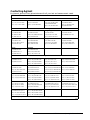
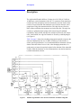
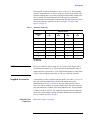
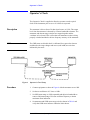
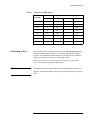
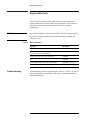
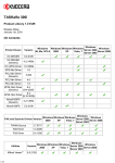
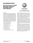
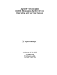
Agilent Technologies
8495D/K Attenuators
Operating and Service
Manual
Agilent Part Number: 08495-90027
Printed in USA
Print Date: July 2004
Supersedes: July 2002
Notice
RESTRICTED RIGHTS LEGEND
If software is for use in the performance of a U.S. Government
prime contract or subcontract, Software is delivered and licensed
as “Commercial computer software” as defined in DFAR
252.227-7014 (June 1995), or as a “commercial item” as defined in
FAR 2.101(a) or as “Restricted computer software” as defined in
FAR 52.227-19 (June 1987) or any equivalent agency regulation or
contract clause. Use, duplication or disclosure of Software is
subject to Agilent Technologies’ standard commercial license
terms, and non-DOD Departments and Agencies of the U.S.
Government will receive no greater than Restricted Rights as
defined in FAR 52.227-19(c)(1-2) (June 1987). U.S. Government
users will receive no greater than Limited Rights as defined in
FAR 52.227-14 (June 1987) or DFAR 252.227-7015 (b)(2)
(November 1995), as applicable in any technical data.
Agilent Technologies, Inc.
1400 Fountaingrove Parkway
Santa Rosa, CA 95403-1799, U.S.A.
© Copyright 2000–2002, 2004
Agilent Technologies, Inc.
ii 8495D/K Attenuators Operating And Service Manual
What You’ll Find in This Manual…
•
•
•
•
•
•
•
“Instrument Definition” on page 1
“Description” on page 2
“Specifications” on page 6
“Installation” on page 8
“Operating Instructions” on page 9
“Operator’s Check” on page 10
“Replaceable Parts” on page 12
8495D/K Attenuators Operating And Service Manual iii
Warranty
Custom systems are warranted by contractual agreement between Agilent
Technologies and the customer.
Certification
Agilent Technologies, Inc., certifies that this product met its published
specifications at the time of shipment from the factory. Agilent Technologies
further certifies that its calibration measurements are traceable to the
United States National Institute of Standards and Technology (NIST,
formerly NBS), to the extent allowed by the Institute’s calibration facility,
and to the calibration facilities of other International Standards
Organization members.
Documentation
Warranty
THE MATERIAL CONTAINED IN THIS DOCUMENT IS
PROVIDED "AS IS," AND IS SUBJECT TO BEING CHANGED,
WITHOUT NOTICE, IN FUTURE EDITIONS. FURTHER, TO
THE MAXIMUM EXTENT PERMITTED BY APPLICABLE LAW,
AGILENT DISCLAIMS ALL WARRANTIES, EITHER EXPRESS
OR IMPLIED WITH REGARD TO THIS MANUAL AND ANY
INFORMATION CONTAINED HEREIN, INCLUDING BUT NOT
LIMITED TO THE IMPLIED WARRANTIES OF
MERCHANTABILITY AND FITNESS FOR A PARTICULAR
PURPOSE. AGILENT SHALL NOT BE LIABLE FOR ERRORS
OR FOR INCIDENTAL OR CONSEQUENTIAL DAMAGES IN
CONNECTION WITH THE FURNISHING, USE, OR
PERFORMANCE OF THIS DOCUMENT OR ANY
INFORMATION CONTAINED HEREIN. SHOULD AGILENT
AND THE USER HAVE A SEPARATE WRITTEN AGREEMENT
WITH WARRANTY TERMS COVERING THE MATERIAL IN
THIS DOCUMENT THAT CONFLICT WITH THESE TERMS,
THE WARRANTY TERMS IN THE SEPARATE AGREEMENT
WILL CONTROL.
Assistance
Product maintenance agreements and other customer assistance agreements
are available for Agilent Technologies products.
For assistance, call your local Agilent Technologies Sales and Service Office
(refer to “Contacting Agilent” on page v).
iv 8495D/K Attenuators Operating And Service Manual
Contacting Agilent
By internet, phone, or fax, get assistance with all your test and measurement needs.
Online assistance: www.agilent.com/find/assist
Americas
Brazil
(tel) (+55) 11 4197 3600
(fax) (+55) 11 4197 3800
Mexico
(tel) (+52) 55 5081 9469
(alt) 01800 5064 800
(fax) (+52) 55 5081 9467
Canada
(tel) 877 894 4414
(fax) (+1) 905 282-6495
United States
(tel) 800 829 4444
(alt) (+1) 303 662 3998
(fax) 800 829 4433
Asia Pacific and Japan
Australia
(tel) 1800 629 485
(alt) 1800 143 243
(fax) 1800 142 134
China
(tel) 800 810 0189
(alt) (+86) 10800 650 0021
(fax) 800 820 2816
Hong Kong
(tel) 800 930 871
(alt) (+852) 3197 7889
(fax) (+852) 2 506 9233
India
(tel) 1600 112 929
(fax) 000800 650 1101
Japan
(tel) 0120 421 345
(alt) (+81) 426 56 7832
(fax) 0120 421 678
Malaysia
(tel) 1800 888 848
(alt) 1800 828 848
(fax) 1800 801 664
Singapore
(tel) 1800 375 8100
(alt) (+65) 6 375 8100
(fax) (+65) 6836 0252
South Korea
(tel) 080 769 0800
(alt) (+82) 2 2004 5004
(fax) (+82) 2 2004 5115
Taiwan
(tel) 0800 047 866
(alt) 00801 651 317
(fax) 0800 286 331
Thailand
(tel) 1800 226 008
(alt) (+66) 2 268 1345
(fax) (+66) 2 661 3714
Europe
Finland
(tel) (+358) 10 855 2100
(fax) (+358) 10 855 2923
Austria
(tel) 0820 87 44 11*
(fax) 0820 87 44 22
Belgium
(tel) (+32) (0)2 404 9340
(alt) (+32) (0)2 404 9000
(fax) (+32) (0)2 404 9395
Denmark
(tel) (+45) 7013 1515
(alt) (+45) 7013 7313
(fax) (+45) 7013 1555
France
(tel) 0825 010 700*
(alt) (+33) (0)1 6453 5623
(fax) 0825 010 701*
Germany
(tel) 01805 24 6333*
(alt) 01805 24 6330*
(fax) 01805 24 6336*
Israel
Ireland
(tel) (+353) (0)1 890 924 204 (tel) (+972) 3 9288 500
(alt) (+353) (0)1 890 924 206 (fax) (+972) 3 9288 501
(fax)(+353) (0)1 890 924 024
Italy
(tel) (+39) (0)2 9260 8484
(fax) (+39) (0)2 9544 1175
Luxemburg
(tel) (+32) (0)2 404 9340
(alt) (+32) (0)2 404 9000
(fax) (+32) (0)2 404 9395
Netherlands
(tel) (+31) (0)20 547 2111
(alt) (+31) (0)20 547 2000
(fax) (+31) (0)20 547 2190
Russia
(tel) (+7) 095 797 3963
(alt) (+7) 095 797 3900
(fax) (+7) 095 797 3901
Spain
(tel) (+34) 91 631 3300
(alt) (+34) 91 631 3000
(fax) (+34) 91 631 3301
Sweden
(tel) 0200 88 22 55*
(alt) (+46) (0)8 5064 8686
(fax) 020 120 2266*
Switzerland (French)
(tel) 0800 80 5353 opt. 2*
(alt) (+33) (0)1 6453 5623
(fax) (+41) (0)22 567 5313
Switzerland (German)
(tel) 0800 80 5353 opt. 1*
(alt) (+49) (0)7031 464 6333
(fax) (+41) (0)1 272 7373
Switzerland (Italian)
(tel) 0800 80 5353 opt. 3*
(alt) (+39) (0)2 9260 8484
(fax) (+41) (0)22 567 5314
United Kingdom
(tel) (+44) (0)7004 666666
(alt) (+44) (0)7004 123123
(fax) (+44) (0)7004 444555
(tel) = primary telephone number; (alt) = alternate telephone number; (fax) = FAX number; * = in country number
04/04
8495D/K Attenuators Operating And Service Manual v
Safety and Regulatory Information
Review this product and related documentation to familiarize yourself with
safety markings and instructions before you operate the instrument. This
product has been designed and tested in accordance with international
standards.
WARNING
The WARNING notice denotes a hazard. It calls attention to a procedure,
practice, or the like, that, if not correctly performed or adhered to, could result
in personal injury. Do not proceed beyond a WARNING notice until the
indicated conditions are fully understood and met.
CAUTION
The CAUTION notice denotes a hazard. It calls attention to an operating
procedure, practice, or the like, which, if not correctly performed or adhered
to, could result in damage to the product or loss of important data. Do not
proceed beyond a CAUTION notice until the indicated conditions are fully
understood and met.
vi 8495D/K Attenuators Operating And Service Manual
Instrument Markings
!
When you see this symbol on your instrument, you should refer to the instrument’s
instruction manual for important information.
This symbol indicates hazardous voltages.
The laser radiation symbol is marked on products that have a laser output.
This symbol indicates that the instrument requires alternating current (ac) input.
The CE mark is a registered trademark of the European Community. If it is
accompanied by a year, it indicates the year the design was proven.
The CSA mark is a registered trademark of the Canadian Standards Association.
1SM1-A
This text indicates that the instrument is an Industrial Scientific and Medical Group 1
Class A product (CISPER 11, Clause 4).
This symbol indicates that the power line switch is ON.
This symbol indicates that the power line switch is OFF or in STANDBY position.
Safety Earth
Ground
Before Applying
Power
This is a Safety Class I product (provided with a protective earthing
terminal). An uninterruptible safety earth ground must be provided from the
main power source to the product input wiring terminals, power cord, or
supplied power cord set. Whenever it is likely that the protection has been
impaired, the product must be made inoperative and secured against any
unintended operation.
Verify that the product is configured to match the available main power
source as described in the input power configuration instructions in this
manual. If this product is to be powered by autotransformer, make sure the
common terminal is connected to the neutral (grounded) side of the ac power
supply.
8495D/K Attenuators Operating And Service Manual vii
viii 8495D/K Attenuators Operating And Service Manual
Instrument Definition
This manual contains installation, operation, and test information for the
8495D and 8495K.
Instruments Covered by
Manual
The instruments covered by this manual have a two-part serial number. The
first four digits and letter comprise the serial number prefix. The last five
digits form the sequential suffix that is unique to each instrument. The
contents of this manual apply to instruments with the following serial
prefixes:
8495D:
1711A
2406A
2508A
2544A
2852A
8495K:
1711A
2406A
2508A
2544A
2808A
3308A
An attenuator manufactured after the printing of this manual may have a
serial prefix that is not listed above. This unlisted serial prefix indicates that
the attenuator is different from those documented in this manual.
8495D/K Attenuators Operating And Service Manual 1
Description
Description
The Agilent 8495D and 8495K are 50-ohm, dc to 26.5 GHz, 0-70 dB (in
10 dB steps), coaxial attenuators with APC 3.5 connectors. Each attenuator
is made up of four attenuation sections connected in cascade. Each section
consists of a precision thin-film attenuator card, a lossless thru-line, and a
ganged pair of edge line transmission lines. The edge lines are flexed to
make contact with either the attenuator card or the thru-line. The edge line
contacts are gold-plated leaf springs which ensure long life and high
repeatability. In the 8495D, the edge line controls are flexed by low-torque
cams. In the 8495K, the edge line controls are flexed by solenoid plungers
(see Figure 1).
Table 1 on page 3 shows the switching arrangement required to increase the
amount of attenuation from 0 to 70 dB in 10 dB steps. In the 8495K, to
ensure specified performance, it is recommended that the attenuator sections
shown in the table below be used. Also, when changing attenuation, it is
good practice to insert the required sections before deletion of the unneeded
sections. With the attenuator set for 0 dB attenuation, only the insertion loss
(residual attenuation) remains.
Figure 1
8495K Programmable Four-Section Attenuator Schematic Diagram
2 8495D/K Attenuators Operating And Service Manual
Description
In the 8495K, each solenoid requires a drive of 20 to 30 V. The switching
current is approximately 125 mA at 24 Vdc per section for the 8495K. The
solenoid switching time is less than 20 milliseconds including settling time.
Once switched, the solenoid plungers are held in place by permanent
magnets and the solenoid plungers automatically disconnect the selected coil
drive and connect the opposite coil drive (see Figure 1 on page 2 and
Figure 3 on page 5).
Table 1
Attenuator Switching
Attenuator Sections
Attenuation
(dB)
1
10 dB
10
X
2
20 dB
20
30
X
40
50
X
60
70
X
3
20 dB
4
20 dB
X*
X**
X*
X**
X
X
X
X
X
X
X
X
X
X
* D model only
** K model only
CAUTION
Do not exceed the RF power rating of 1 W average or 100 W peak with a
maximum pulse width of 10 µs. Do not connect an attenuator RF input or
output connector to greater the ±7 Vdc. If the attenuator must be connected to
a device with a potential greater than ±7 Vdc, use a blocking capacitor.
Supplied Accessories
A solenoid drive cable is supplied with the 8495K. The cable is 1.5 m (5 ft)
long with a mating connector plug on one end and the other end is
unterminated (see Figure 2 on page 4). The part number for this cable is
8120-2178, and is available as a spare or replacement. The cable connector
plug and contacts are available from Viking Industries Inc. The part number
is TKP12-100-P-TS-100-AU. The connector plug and contacts without the
cable can be ordered from a Viking distributor. Information on replaceable
parts is available in Table 3 on page 5.
Solenoid Cable
Connectors
Refer also to Figure 2 on page 4.
8495D/K Attenuators Operating And Service Manual 3
Description
Table 2
Section
Section 1
Solenoid Cable Connectors
Section 2
Section 3
Section 4
Power
Solenoid Coil
Thru-Line
Atten
Card
Thru-Line
Atten
Card
Thru-Line
Atten
Card
Thru-Line
Atten
Card
V+
Cable Wire
Color Code1
VIO
YEL
BLK
GRN
ORG
BLU
BRN
WHT
RED
Connector
Plug Pin
Number 2
5
6
7
8
9
10
11
12
1
8495K
0 dB
10 dB
0 dB
20 dB
0 dB
20 dB
0 dB
20 dB
–
Option 016
13
2
11
5
3
9
4
10
6
Flat Pack
Plug Pin
Number3
1. Five-foot cable and mating plug assembly provided.
2. Pin 1 (red wire) is common for all coils. Pins 2, 3 and 4 are not used.
3. Pin 6 is common for all coils. Pins 1, 7, 8, 12, and 14 are not used.
Figure 2
Solenoid Cable Pin Configuration
4 8495D/K Attenuators Operating And Service Manual
Description
Table 3
Solenoid Cable Replaceable Parts
Part Number
Description
2220-0006
Screw, fillister Head 4-40x7/8 in. (for attaching base)
8120-2178
Cable, solenoid drive, 1.5 meters (5 feet) long, connector plug
on one end and other end unterminated (8495K)
0370-1091
Knob (84950)
08496-20008
Base
TKP12-100-P-TS-100-AU 1
Connector Plug and Contacts only without cable (8495K)
1. Available from Viking Industries, Inc., Chatsworth, California 91311.
Figure 3
Typical Solenoid Coil Driver Circuit
8495D/K Attenuators Operating And Service Manual 5
Specifications
Specifications
Frequency Range
and Attenuation
Frequency Range
dc to 26.5 GHz
Attenuation
0 to 70 dB in 10 dB steps
Attenuation Accuracy
Attenuation Accuracy (± dB, referenced from 0 dB)
Maximum Insertion Loss
Attenuation Repeatability
RF Power Handling
Capability
Solenoid Drive
Switching speed
Attenuation
Selection (dB)
dc–6.0 GHz
6.0–12.4 GHz
12.4–18.0 GHz
18.0–26.5 GHz
10
0.3
0.4
0.5
0.7
20
0.5
0.5
0.6
0.8
30
0.6
0.7
0.8
1.0
40
0.7
0.9
1.1
1.5
50
0.8
1.0
1.2
1.6
60
1.0
1.3
1.4
1.9
70
1.1
1.5
1.7
2.3
(0.4 + 0.09 f) dB
where “f” is the frequency in GHz
0.01 dB, dc to 18.0 GHz
0.05 dB, 18.0 to 26.5 GHz
1 W average, 100 W peak with maximum pulse width of 10 microseconds
For Agilent 8495K only.
Solenoids Drive
Coil Voltage
Switching Current
8495K
20 to 30 Vdc
125 mA at 24V (approx.)
Maximum 20 milliseconds including settling time
6 8495D/K Attenuators Operating And Service Manual
Specifications
Maximum SWR
Instrument
Frequency Range (GHz)
Maximum SWR
8495D, 8495K
dc to 6.0
6.0 to 12.4
12.4 to 18
18 to 26.5
1.25
1.45
1.9
2.2
Physical Characteristics
Instrument
Dimensions 1
(depth x width x height)
Weight
8495D
6.25 in x 2.0625 in x 1.6875 in
159 mm x 52 mm x 43 mm
15 oz
5.625 in x 2.0625 in x 1.6875 in
159 mm x 52 mm x 43 mm
16 oz
8495K
425 g
454g
1. Dimensions are in millimeters and inches. Dimensions are for general information only. If
dimensions are required for building special enclosures, contact your Agilent field engineer.
Minimum Life
Environment Limits
NOTE
>5 million cycles per section
The attenuator should be stored in a clean, dry environment. The storage and
operating environments of the instruments should be within the following
limits.
Characteristic
Storage Value
Operating Value
Temperature
–40 to +75 °C
0 to 55 °C
Humidity
< 95% relative
< 95% relative
Altitude
< 7600 m (25000 ft)
< 4600 m (15000 ft)
Containers and materials identical to those used in factory packaging are
available through Agilent Technologies offices. If the instrument is being
returned to Agilent Technologies for servicing, attach a tag indicating the
type of service required, return address, model number, and full serial
number. Also, mark the container FRAGILE to assure careful handling. In
any correspondence, refer to the instrument by model number and full serial
number.
8495D/K Attenuators Operating And Service Manual 7
Installation
Installation
Initial Inspection
Inspect the shipping container for damage. If the shipping container or
cushioning material is damaged, it should be kept until the contents of the
shipment have been checked for completeness and the instrument has been
checked mechanically and electrically. A procedure for checking electrical
performance is given under “Operator’s Check” on page 10 (also see
“Performance Tests” on page 11). If the contents of the shipment are
incomplete, if there is mechanical damage or defect, or if the instrument
does not pass the electrical performance test, notify the nearest Agilent
Technologies office. If the shipping container is damaged, or the cushioning
material shows signs of stress, notify the carrier as well as the Agilent
Technologies office. Keep the shipping materials for the carrier's inspection.
The Agilent office will arrange for repair or replacement without waiting for
claim settlement.
Mating Connectors
The APC 3.5 connector is a 3.5-mm air line connector that will mate with
the SMA type connectors. The SWR performance of this hybrid connection
is similar to a mated pair of SMA connectors when used within the
frequency range of the SMA connector.
Option
The attenuators are configured with the APC 3.5 female connectors and are
designated as Option 004.
CAUTION
When installing the instrument, make sure that the connectors do not support
weight or bear torque. The preferred procedure is to set up all equipment in
position before connecting the instrument. Either connector may be used as
the input or output connector.
Installation
Instructions
The 8495K solenoid drive cable connector plug is connected by aligning the
plug (P1) with the jack (J1) on the attenuator, and then pushing the plug over
the jack. The plug is removed by grasping the ribbed sides of the plug and
squeezing them together while pulling back until the plug clears the jack.
8 8495D/K Attenuators Operating And Service Manual
Operating Instructions
Operating Instructions
CAUTION
Do not apply power greater than 1 W average, or 100 W peak with a
maximum pulse width of 10 microseconds. If these limits are exceeded, the
attenuators may be damaged.
CAUTION
For the 8495K, do not ground both solenoid drive pins of the programmable
attenuator at the same time. This causes rapid cycling of the solenoid and
could reduce the operating life of the attenuator. The rapid cycling may
produce a buzzing sound from the attenuator.
Operating Information
Either RF connector may be used as the input or output connector. Connect
the solenoid drive cable of the programmable attenuator to the solenoid drive
connector (Jl). By applying the proper voltage and grounds to the proper
pins of Jl, the attenuator will either increase or decrease the amount of
attenuation as selected.
8495D/K Attenuators Operating And Service Manual 9
Operator’s Check
Operator’s Check
The Operator's Check is supplied to allow the operator to make a quick
check of the instrument prior to use or if a failure is suspected.
Description
The attenuator is driven from a 50-ohm signal source at 1 kHz. The output
level from the attenuator is detected by a narrow-bandwidth voltmeter. The
attenuator and detector range switches are stepped together and the
variations in level noted. This verifies that each attenuator section is being
properly switched and checks the low-frequency accuracy of the attenuator.
NOTE
The SWR meter used in this check is calibrated for a square-law detector
and therefore the range changes and errors (read in dB) are twice that
indicated by the meter.
Figure 4
Procedure
Operator’s Check Setup
1. Connect equipment as shown in Figure 4 with the attenuator set to 0 dB.
2. Set the test oscillator to 0.3 Vrms at 1 kHz.
3. Set SWR meter range to 2 dB (expanded) and adjust its bandwidth to
center of adjustment range. Fine tune oscillator frequency to obtain
maximum meter indication.
4. Set attenuator and SWR meter range switch as shown in Table 4 and
verify that SWR meter indicates within the limits shown.
10 8495D/K Attenuators Operating And Service Manual
Operator’s Check
Table 4
Attenuator and SWR Settings
SWR Meter
Range (dB)
Attenuation
2
0
6
10
1.20
1.80
12
20
0.15
0.85
16
30
1.05
1.95
221
40
–0.40
1.40
261
50
0.50
2.50
321
60
–0.60
1.60
361
70
0.35
2.65
8495D/K
Meter Indication (dB)
Minimum
Actual
Maximum
Set to 0.5
1. Adjust range by 2 dB, if needed, to obtain a on-scale indication.
Performance Tests
The attenuator can be tested to the accuracy of the Specifications on page 6
with an automatic network analyzer or equivalent equipment of suitable
accuracy. If an automatic network analyzer is available, test the attenuator
using the procedures in the analyzer's operating manual.
Refer to the Agilent 11713A Attenuator/Switch Driver Operating and
Service Manual for programming instructions.
NOTE
The attenuators have no internal adjustments and should not be opened. If
defective, return the attenuator to the nearest Agilent Technologies office for
repair.
8495D/K Attenuators Operating And Service Manual 11
Replaceable Parts
Replaceable Parts
Table 5 lists the replaceable parts which are the only parts that can be
replaced without access to the interior of the instrument. If any parts not
listed below need replacement, return the instrument to Agilent
Technologies.
CAUTION
Due to special fixtures necessary for assembly, do NOT attempt to replace
any parts not listed in the table below. If the instrument is opened, the
warranty is void.
Table 5
Replaceable Parts
Description
Part Number
Knob (8495D)
0370-1091
Cable, solenoid drive, 1.5 m (5 ft) long, connector plug on one
end and other end un-terminated (8495K)
8120-2178
Screws for both bases: 4-40 x 7/8 in. Fillister head
2220-0006
Base
5041-3888
Connector plug and contacts only without cable (8495K)
*TKP12-100-P-TS-100-AU
*Available from distributors of Viking Industries, Inc., Chatsworth CA 91311
Troubleshooting
Troubleshooting consists of performing the “Operator’s Check” on page 10.
If the instrument does not perform within limits, return the instrument to
Agilent Technologies.
12 8495D/K Attenuators Operating And Service Manual