1
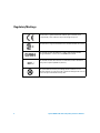
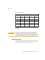
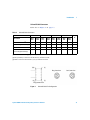
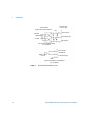
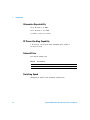
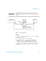
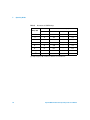
Agilent 8495D/K
Attenuators
Operating and Service
Manual
Agilent Technologies
Notices
© Agilent Technologies, Inc. 2011
Warranty
No part of this manual may be reproduced in
any form or by any means (including electronic storage and retrieval or translation
into a foreign language) without prior agreement and written consent from Agilent
Technologies, Inc. as governed by United
States and international copyright laws.
The material contained in this document is provided “as is,” and is subject to being changed, without notice,
in future editions. Further, to the maximum extent permitted by applicable
law, Agilent disclaims all warranties,
either express or implied, with regard
to this manual and any information
contained herein, including but not
limited to the implied warranties of
merchantability and fitness for a particular purpose. Agilent shall not be
liable for errors or for incidental or
consequential damages in connection with the furnishing, use, or performance of this document or of any
information contained herein. Should
Agilent and the user have a separate
written agreement with warranty
terms covering the material in this
document that conflict with these
terms, the warranty terms in the separate agreement shall control.
Manual Part Number
08495-90027
Edition
Third Edition, January 2011
Printed in Malaysia
Agilent Technologies, Inc.
Phase 3 Bayan Lepas Free Industrial Zone
Bayan Lepas, Penang 11900 Malaysia
Safety Notices
Technology Licenses
The hardware and/or software described in
this document are furnished under a license
and may be used or copied only in accordance with the terms of such license.
Restricted Rights Legend
U.S. Government Restricted Rights. Software and technical data rights granted to
the federal government include only those
rights customarily provided to end user customers. Agilent provides this customary
commercial license in Software and technical data pursuant to FAR 12.211 (Technical
Data) and 12.212 (Computer Software) and,
for the Department of Defense, DFARS
252.227-7015 (Technical Data - Commercial
Items) and DFARS 227.7202-3 (Rights in
Commercial Computer Software or Computer Software Documentation).
2
CAUTION
A CAUTION notice denotes a hazard. It calls attention to an operating procedure, practice, or the likes
of that, if not correctly performed
or adhered to, could result in damage to the product or loss of important data. Do not proceed beyond a
CAUTION notice until the indicated
conditions are fully understood and
met.
WA R N I N G
A WARNING notice denotes a
hazard. It calls attention to an
operating procedure, practice, or
the likes of that, if not correctly
performed or adhered to, could
result in personal injury or death.
Do not proceed beyond a WARNING notice until the indicated
conditions are fully understood
and met.
Agilent 8495D/K Attenuators Operating and Service Manual
Certification
Agilent Technologies certifies that this product met its published
specifications at the time of shipment from the factory. Agilent
Technologies further certifies that its calibration measurements are
traceable to the United States National Institute of Standards and
Technology (NIST, formerly NBS), to the extend allowed by the
Institute’s calibration facility, and to the calibration facilities of the
other International Standards Organization members.
WEEE Compliance
This product complies with the WEEE Directive (2002/96/EC)
marking requirements. The affixed label indicates that you must
not discard this electrical/electronic product in domestic household
waste.
Product Category: With reference to the equipment types in the
WEEE Directive Annex I, this product is classed as a "Monitoring
and Control Instrumentation" product.
Do not dispose in domestic household waste.
To return unwanted products, contact your local Agilent office, or
see www.agilent.com for more information.
Agilent 8495D/K Attenuators Operating and Service Manual
3
Regulatory Markings
The CE mark is a registered trademark of the European Community. If it is
accompanied by a year, it indicates the year the design was proven.
The CSA mark is a registered trademark of the Canadian Standards Association.
This text indicates that this ISM device complies with Canadian ICES-001.
Cet appareill ISM est conforme a la norme NMB-001 du Canada.
This text indicates that the instrument is an Industrial Scientific and Medical
Group 1 Class A product (CISPER 11, Clause 4).
This symbol indicates the time period during which no hazardous or toxic
substance elements are expected to leak or deteriorate during normal use. Forty
years is the expected useful life of the product.
4
Agilent 8495D/K Attenuators Operating and Service Manual
Contacting Agilent
For more information, please contact your nearest Agilent office.
Americas
Canada
Latin America
United States
(877) 894-4414
305 269 7500
(800) 829-4444
Asia Pacific
Australia
China
Hong Kong
India
Japan
Korea
Malaysia
Singapore
Taiwan
Thailand
1 800 629 485
800 810 0189
800 938 693
1 800 112 929
81 426 56 7832
080 769 0800
1 800 888 848
1 800 375 8100
0800 047 866
1 800 226 008
Europe
Austria
Belgium
Denmark
Finland
France
Germany
Ireland
Italy
Netherlands
Spain
Sweden
Switzerland(French)
Switzerland(German)
United Kingdom
Other European Countries:
0820 87 44 11
32 (0) 2 404 93 40
45 70 13 15 15
358 (0) 10 855 2100
0825 010 700
01805 24 6333
1890 924 204
39 02 92 60 8484
31 (0) 20 547 2111
34 (91) 631 3300
0200-88 22 55
41 (21) 8113811 (Opt 2)
0800 80 53 53 (Opt 1)
44 (0) 118 9276201
www.agilent.com/find/contactus
Or, go to www.agilent.com/find/assist for more information.
Agilent 8495D/K Attenuators Operating and Service Manual
5
This page is intentionally left blank.
6
Agilent 8495D/K Attenuators Operating and Service Manual
Contents
1
Introduction
9
Product Overview 10
Supplied Accessories
12
Specifications 15
Frequency Range and Attenuation 15
Attenuation Accuracy 15
Maximum Insertion Loss 15
Attenuation Repeatability 16
RF Power Handling Capability 16
Solenoid Drive 16
Switching Speed 16
Maximum SWR 17
Operating Life 17
2
Environmental Specifications & Physical Dimensions
Environmental Specifications
Physical Dimensions
3
Operating Guides
19
20
21
25
Installation 26
Initial Inspection 26
Mating Connectors 27
Installation Instructions 27
Operating Instructions 28
Operating Information 28
Operator’s Check 28
Performance Tests 31
Service Instructions 31
Agilent 8495D/K Attenuators Operating and Service Manual
7
This page is intentionally left blank.
8
Agilent 8495D/K Attenuators Operating and Service Manual
Agilent 8495D/K Attenuators
Operating and Service Manual
1
Introduction
Product Overview 10
Supplied Accessories 12
Specifications 15
Frequency Range and Attenuation 15
Attenuation Accuracy 15
Maximum Insertion Loss 15
Attenuation Repeatability 16
RF Power Handling Capability 16
Solenoid Drive 16
Switching Speed 16
Maximum SWR 17
Operating Life 17
This manual contains operating instructions for the Agilent
8495D/K Attenuators. Included in the manual is information
required to install and test these attenuators.
Agilent Technologies
9
1
Introduction
Product Overview
The Agilent 8495D and 8495K are 50- ohm, dc to 26.5 GHz,
0 dB to 70 dB (in 10 dB steps), coaxial attenuators with APC 3.5
connectors. Each attenuator is made up of four attenuation
sections connected in cascade. Each section consists of a precision
thin- film attenuator card, a lossless thru- line, and a ganged pair of
edge line transmission lines. The edge lines are flexed to make
contact with either the attenuator card or the thru- line. The edge
line contacts are gold- plated leaf springs which ensure long life
and high repeatability. In the 8495D, the edge line controls are
flexed by low- torque cams. In the 8495K, the edge line controls
are flexed by solenoid plungers (see Figure 1).
Table 1 on page 12 shows the switching arrangement required to
increase the amount of attenuation from 0 dB to 70 dB in 10 dB
steps. In the 8495K, to ensure specified performance, it is
recommended that the attenuator sections shown in the table
below be used. Also, when changing attenuation, it is good practice
to insert the required sections before deletion of the unneeded
sections. With the attenuator set for 0 dB attenuation, only the
insertion loss (residual attenuation) remains.
10
Agilent 8495D/K Attenuators Operating and Service Manual
Introduction
1
From
solenoid
driver
circuits
+24 Vdc
Thru line
Wire
color
code
Thru line
Thru line
Thru line
RF
output
RF input
Attenuator card
10 dB
Figure 1
Attenuator card
20 dB
Attenuator card
20 dB
Attenuator card
20 dB
8495K Programmable Four-Section Attenuator Schematic Diagram
In the 8495K, each solenoid requires a drive of 20 V to 30 V. The
switching current is approximately 125 mA at 24 Vdc per section
for the 8495K. The solenoid switching time is less than
20 milliseconds including settling time. Once switched, the solenoid
plungers are held in place by permanent magnets and the solenoid
plungers automatically disconnect the selected coil drive and
connect the opposite coil drive (see Figure 1 on page 11 and
Figure 3 on page 14).
Agilent 8495D/K Attenuators Operating and Service Manual
11
1
Introduction
Table 1
Attenuator Switching
Attenuator Sections
Attenuation
(dB)
1
10 dB
10
×
2
20 dB
20
30
×
40
50
×
60
70
×
3
20 dB
4
20 dB
×[1]
×[2]
×[1]
×[2]
×
×
×
×
×
×
×
×
×
×
[1] D model only
[2] K model only
CAUTION
Do not exceed the RF power rating of 1 W average or 100 W peak with a
maximum pulse width of 10 μs. Do not connect an attenuator RF input or
output connector to greater than ±7 Vdc. If the attenuator must be connected
to a device with a potential greater than ±7 Vdc, use a blocking capacitor.
Supplied Accessories
A solenoid drive cable is supplied with the 8495K. The cable is
1.5 m (5 ft) long with a mating connector plug on one end and the
other end is unterminated (see Figure 2 on page 13).
12
Agilent 8495D/K Attenuators Operating and Service Manual
Introduction
1
Solenoid Cable Connectors
Refer also to Figure 2 on page 13.
Table 2
Solenoid Cable Connectors
Section
Section 1
Solenoid Coil
Cable Wire Color Code[1]
Connector Plug Pin Number
[2]
8495K
Option 016
Flat Pack Plug Pin Number[3]
Section 2
Section 3
Section 4
Power
V+
ThruLine
Atten
Card
ThruLine
Atten
Card
ThruLine
Atten
Card
ThruLine
Atten
Card
PUR
YEL
BLK
GRN
ORN
BLU
BRN
WHT
RED
5
6
7
8
9
10
11
12
1
0 dB
10 dB
0 dB
20 dB
0 dB
20 dB
0 dB
20 dB
–
13
2
11
5
3
9
4
10
6
[1] Five-foot cable and mating plug assembly provided.
[2] Pin 1 (red wire) is common for all coils. Pins 2, 3, and 4 are not used.
[3] Pin 6 is common for all coils. Pins 1, 7, 8, 12, and 14 are not used.
(1)
(14)
Plug, front view
(8)
Jack, front view
(7)
Plug, bottom view
Figure 2
Solenoid Cable Pin Configuration
Agilent 8495D/K Attenuators Operating and Service Manual
13
1
Introduction
Solenoid cable
connector jack
Solenoid driver
Any 75451 dual peripheral AND driver.
+24 V
Atten card pin
TTL Input
1820-0175
Solenoid drive pin
+5 VDC
Thru-line pin
Typical Solenoid IC Driver Circuit
(3 or 4 required)
Atten card pin
Thru-line pin
Switch or relay
contacts
Solenoid drive pin
+24 Vdc
Typical Solenoid Relay or Switch Driver
(3 or 4 required)
Figure 3
14
Typical Solenoid Coil Driver Circuit
Agilent 8495D/K Attenuators Operating and Service Manual
Introduction
1
Specifications
Frequency Range and Attenuation
Table 3
Frequency Range and Attenuation
Frequency Range
dc to 26.5 GHz
Attenuation
0 dB to 70 dB in 10 dB steps
Attenuation Accuracy
Table 4
Attenuation Accuracy
Attenuation Accuracy (± dB, referenced from 0 dB)
Attenuation
Selection (dB)
dc–6.0 GHz
6.0–12.4 GHz
12.4–18.0 GHz
18.0–26.5 GHz
10
0.3
0.4
0.5
0.7
20
0.5
0.5
0.6
0.8
30
0.6
0.7
0.8
1.0
40
0.7
0.9
1.1
1.5
50
0.8
1.0
1.2
1.6
60
1.0
1.3
1.4
1.9
70
1.1
1.5
1.7
2.3
Maximum Insertion Loss
(0.4 + 0.09 f) dB
where “f” is the frequency in GHz.
Agilent 8495D/K Attenuators Operating and Service Manual
15
1
Introduction
Attenuation Repeatability
±0.03 dB max to 18 GHz
±0.05 dB max to 26.5 GHz
(5 million cycles per section)
RF Power Handling Capability
1 W average, 100 W peak with maximum pulse width of
10 microseconds.
Solenoid Drive
For Agilent 8495K only.
Table 5
Solenoid Drive
Solenoid Drive
Coil Voltage
Switching Current
8495K
20 Vdc to 30 Vdc
125 mA at 24 V (approx.)
Switching Speed
Maximum 20 milliseconds including settling time.
16
Agilent 8495D/K Attenuators Operating and Service Manual
Introduction
1
Maximum SWR
Table 6
Maximum SWR
Instrument
Frequency Range (GHz)
Maximum SWR
8495D, 8495K
dc to 6.0
6.0 to 12.4
12.4 to 18.0
18.0 to 26.5
1.25
1.45
1.9
2.2
Operating Life
5 million cycles per section.
Agilent 8495D/K Attenuators Operating and Service Manual
17
1
Introduction
This page is intentionally left blank.
18
Agilent 8495D/K Attenuators Operating and Service Manual
Agilent 8495D/K Attenuators
Operating and Service Manual
2
Environmental Specifications &
Physical Dimensions
Environmental Specifications 20
Physical Dimensions 21
This chapter contains the environmental tests on the Agilent
8495D/K Attenuators that fully comply with Agilent
Technologies’ product operating environmental specifications.
The physical dimensions are illustrated in the
later section.
Agilent Technologies
19
2
Environmental Specifications & Physical Dimensions
Environmental Specifications
The Agilent 8495D/K Attenuators are designed to fully comply with
Agilent Technologies’ product operating environmental
specifications as shown in Table 7.
Table 7
Environmental Specifications
Temperature:
• Operating
0 °C to +55 °C
• Storage
–40 °C to +75 °C
Humidity:
• Operating
<95% relative
• Storage
<95% relative
Altitude:
• Operating
<4600 m (15000 ft)
• Storage
<7600 m (25000 ft)
Shock:
• Operating
10 Gs, six ms, on six sides, three blows
• Non-operating
500 Gs, 1.8 ms, in six directions
Vibration:
• Operating
EMC
20
5 Gs, 34 Hz to 2000 Hz
Radiated interference is within the requirements of
MIL-STD-461, RE02
Agilent 8495D/K Attenuators Operating and Service Manual
Environmental Specifications & Physical Dimensions
2
Physical Dimensions
Table 8 shows the physical dimensions of the Agilent 8495D/K
Attenuators.
Table 8
Physical Dimensions
Instrument
Dimensions[1]
Weight
8495D
Per Figure 4
15 oz
425 g
8495K
Per Figure 5
16 oz
454 g
[1] Dimensions are in millimeters and inches. Dimensions are for general information only.
If dimensions are required for building special enclosures, contact your Agilent
field engineer.
Agilent 8495D/K Attenuators Operating and Service Manual
21
2
Environmental Specifications & Physical Dimensions
Figure 4
22
Dimensions of Agilent 8495D Attenuator
Agilent 8495D/K Attenuators Operating and Service Manual
Environmental Specifications & Physical Dimensions
Figure 5
2
Dimensions of Agilent 8495K Attenuator
Agilent 8495D/K Attenuators Operating and Service Manual
23
2
Environmental Specifications & Physical Dimensions
This page is intentionally left blank.
24
Agilent 8495D/K Attenuators Operating and Service Manual
Agilent 8495D/K Attenuators
Operating and Service Manual
3
Operating Guides
Installation 26
Initial Inspection 26
Mating Connectors 27
Installation Instructions 27
Operating Instructions 28
Operating Information 28
Operator’s Check 28
Performance Tests 31
Service Instructions 31
This chapter describes the installation of the Agilent
8495D/K Attenuators. The operating instruction quick- check
procedure is included for verification test prior to usage.
Agilent Technologies
25
3
Operating Guides
Installation
Initial Inspection
1 Inspect the shipping container for damage. If the shipping
container or cushioning material is damaged, it should be kept
until the contents of the shipment have been checked for
completeness and the instrument has been checked both
mechanically and electrically.
• Check for mechanical damage such as scratches or dents.
• Procedures for checking electrical performance are given
under “Operator’s Check” on page 28 or “Performance
Tests” on page 31.
2 If the contents are incomplete, if there is mechanical damage or
defect, or if the instrument does not pass the electrical
performance test, contact the nearest Agilent Technologies Sales
and Service office. Refer to the Service and Support information
in the front matter of this manual. Agilent Technologies will
arrange for repair or replacement of the damaged or defective
equipment. Keep the shipping materials for the carrier's
inspection.
3 If you are returning the instrument under warranty or for
service, repackaging the instrument requires original shipping
containers and materials or their equivalents. Agilent
Technologies can provide packaging materials identical to the
original materials. Refer to Service and Support information in
the front matter of this manual for the Agilent Technologies
nearest to you. Attach a tag indicating the type of service
required, return address, model number and serial number.
Mark the container FRAGILE to insure careful handling. In any
correspondence, refer to the instrument by model number and
serial number.
26
Agilent 8495D/K Attenuators Operating and Service Manual
Operating Guides
3
Mating Connectors
The APC 3.5 connector is a 3.5- mm air line connector that will
mate with the SMA type connectors. The SWR performance of this
hybrid connection is similar to a mated pair of SMA connectors
when used within the frequency range of the SMA connector.
Option
The attenuators are configured with the APC 3.5 female connectors
and are designated as Option 004.
CAUTION
When installing the instrument, make sure that the connectors do not support
weight or bear torque. The preferred procedure is to set up all equipment in
position before connecting the instrument. Either connector may be used as
the input or output connector.
Installation Instructions
The 8495K solenoid drive cable connector plug is connected by
aligning the plug (P1) with the jack (J1) on the attenuator, and
then pushing the plug over the jack. The plug is removed by
grasping the ribbed sides of the plug and squeezing them together
while pulling back until the plug clears the jack.
Agilent 8495D/K Attenuators Operating and Service Manual
27
3
Operating Guides
Operating Instructions
CAUTION
Do not apply RF power greater than 1 W average, or 100 W peak with a
maximum pulse width of 10 microseconds. If these limits are exceeded, the
attenuators may be damaged.
CAUTION
For the 8495K, do not ground both solenoid drive pins of the programmable
attenuator at the same time. This causes rapid cycling of the solenoid and
could reduce the operating life of the attenuator. The rapid cycling may
produce a buzzing sound from the attenuator.
Operating Information
Either RF connector may be used as the input or output
connector. Connect the solenoid drive cable of the programmable
attenuator to the solenoid drive connector (Jl). By applying the
proper voltage and grounds to the proper pins of Jl, the attenuator
will either increase or decrease the amount of attenuation
as selected.
Operator’s Check
The Operator's Check is supplied to allow the operator to make a
quick check of the instrument prior to use or if a failure
is suspected.
Description
The attenuator is driven from a 50- ohm signal source at 1 kHz.
The output level from the attenuator is detected by a
narrow- bandwidth voltmeter. The attenuator and detector range
switches are stepped together and the variations in level noted.
This verifies that each attenuator section is being properly
switched and checks the low- frequency accuracy of the attenuator.
28
Agilent 8495D/K Attenuators Operating and Service Manual
Operating Guides
NOTE
3
The SWR meter used in this check is calibrated for a square-law detector.
Therefore, the range changes and errors (read in dB) are twice that indicated by
the meter.
Test oscillator
SWR meter
8495D manual
attenuator
Adapter
50 Ω
Input
8495K programmable
attenuator
Figure 6
Solenoid
driver circuits
Operator’s Check Setup
Procedure
1 Connect equipment as shown in Figure 6 on page 29 with the
attenuator set to 0 dB.
2 Set the test oscillator to 0.3 Vrms at 1 kHz.
3 Set SWR meter range to 2 dB (expanded) and adjust its
bandwidth to center of adjustment range. Fine- tune the
oscillator frequency to obtain maximum meter indication.
4 Set attenuator and SWR meter range switch as listed in Table 9
and verify that the SWR meter indicates within the limits
shown.
Agilent 8495D/K Attenuators Operating and Service Manual
29
3
Operating Guides
Table 9
Attenuator and SWR Settings
SWR Meter
Range (dB)
Attenuation
Meter Indication (dB)
8495D/K
Minimum
Actual
Maximum
2
0
–
Set to 0.5
–
6
10
1.20
–
1.80
12
20
0.15
–
0.85
16
30
1.05
–
1.95
22[1]
40
–0.40
–
1.40
[1]
26
50
0.50
–
2.50
32[1]
60
–0.60
–
1.60
36[1]
70
0.35
–
2.65
[1] Adjust range by 2 dB, if needed, to obtain an on-scale indication.
30
Agilent 8495D/K Attenuators Operating and Service Manual
Operating Guides
3
Performance Tests
The Agilent 8495D/K Attenuators can be tested to the accuracy of
the specifications with a network analyzer or equivalent equipment
of suitable accuracy. If a network analyzer is available, test
instrument using the procedure in the analyzer's operating manual.
Service Instructions
Adjustment
The Agilent 8495D/K Attenuators do not have internal adjustments
and should not be opened.
Repair
The Agilent 8495D/K Attenuators are not recommended for repair
as most components are not easily removed.
Maintenance
The connectors, particularly the connector faces, must be kept
clean. For instruction on connecting and care of your connectors,
refer to Microwave Connector Care Quick Reference Card
(08510- 90360).
Agilent 8495D/K Attenuators Operating and Service Manual
31
3
Operating Guides
This page is intentionally left blank.
32
Agilent 8495D/K Attenuators Operating and Service Manual