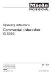
1
Installation instructions Information is subject to change. Please refer to our website to obtain the most current product specification, technical & warranty information. KFNS 37432 iD To prevent accidents and machine damage read these instructions before installation or use. 70 Caring for the environment Disposing of packaging materials Disposing of your old appliance The packaging is designed to protect the appliance from damage during transport. The packaging materials used are selected from materials which are environmentally friendly for disposal and should be recycled. Old electrical and electronic equipment often still contain valuable materials. However, they may also include harmful substances that were essential for proper functioning and safe use. Improperly disposing of these items in your household waste can be harmful to your health and the environment. Therefore, please do not dispose of your old appliance in your regular household waste. Recycling the packaging reduces the use of raw materials in the manufacturing process and also reduces the amount of waste in landfill sites. You can return the packaging to your Miele dealer. Instead, please dispose of your old appliance at your local community waste collection / recycling centre. Take care not to damage the pipework at the back of the appliance before or during transport to an authorized collection depot. By doing so, refrigerant in the pipework and oil in the compressor will be contained and will not leak into the environment. Please ensure that your old appliance does not pose a danger to children while being stored prior to disposal. See "Warning and safety instructions" for more information. 71 Electrical connection ,Failure to follow these instructions can result in death, fire, or electrical shock. Improper connection of the equipment grounding conductor may result in electric shock. If you are in any doubt as to whether the appliance has been properly grounded, have the appliance checked by a qualified electrician or service technician. Installation, repairs and other work by unqualified persons could be dangerous. The manufacturer will not be held responsible for damage or injury arising from unauthorized work. Before installing the appliance, verify that the voltage, load and circuit rating information found on the data plate match the household electrical supply. ,Do not ground to a gas pipe. Check with a qualified elictrician if you are not sure the appliance is properly grounded. Do not have a fuse in the neutral or grounding curcuit. ,Electrocution hazard Electrical grounding required. This appliance is equipped with a three-prong (grounding) polarized plug for your protection against possible shock hazards. Do not remove the round grounding prong from the plug. Do not use a two-prong grounding adapter. Do not use extension cords or ungrounded (two prong) adapters. Connect this appliance to a 110 – 120 VAC, 60 Hz and 15 amp (20 amp for side-by-side) circuit (20 amp for side-by-side) with a circuit breaker or fuse. This appliance should have its own separate grounded circuit. The power cord is equipped with a three-prong (grounding) plug for your protection against potential electrical shock. To maintain this protection: – Do not modify the plug by removing the round grounding prong. – Do not use a two-prong adapter. Where a two-prong wall outlet is encountered, contact a qualified electrician and have it replaced with a three-prong outlet in accordance with the local electrical codes and regulations. – Do not use a power cord that is frayed or damaged. – Do not connect the appliance using an extension cord or extension socket. 72 Electrical connection The appliance must be connected to an electrical outlet that is properly grounded. The electrical installation must comply with the applicable electrical code. The outlet must be easily accessible and not concealed behind the appliance so that the appliance can quickly be disconnected from the electricity supply in an emergency. The plug and power cable must not come into contact with the back of the appliance, as they could be damaged by vibrations from the appliance. This may result in a short circuit. In addition, no other appliances should be plugged into a socket located directly behind this appliance. Do not use an extension cord to connect the appliance to the power supply. Extension cords do not guarantee the required safety of the appliance (e.g. they pose a danger of overheating). Do not connect the appliance to stand-alone inverters, such as those used with an autonomous energy source, e.g. solar power systems. Otherwise, when the appliance is switched on, peak loads in the system can cause the safety shutdown mechanism to be triggered. This can damage electronic units. In addition, the appliance must not be used with energy-saving devices, which reduce the amount of energy supplied to the appliance and cause it to overheat. If the power cable needs to be replaced, this work must only be performed by a qualified electrician. 73 Installation information Location Safe operation of the appliance is only assured if it has been installed and connected in accordance with these operating and installation instructions. WARNING! Danger of tilting! To avoid a hazard due to instability of the appliance, it must be fixde in accordance with the instructions. Side-by-side The KFNS 37432 iD has two side-wall heaters encased in foam and can be built into separate cabinet units arranged side-by-side with all appliances. Please contact your dealer for specific information about which combinations will work with your appliance. This appliance should not be installed near windows where it is exposed to direct sunlight or directly adjacent to heat-producing appliances such as an oven or a radiator. The higher the room temperature, the longer the compressor runs, increasing energy consumption by the appliance. Install the appliance in a dry, well-ventilated room. When installing the appliance, please also note the following: – The power outlet must not be located directly behind the appliance and must be easily accessible in an emergency. – The plug and power cable must not come into contact with the back of the appliance, as they could be damaged by vibrations from the appliance. – In addition, no other appliances should be plugged into a socket located directly behind this appliance. Important! In environments with high humidity condensation can build up on the appliance exterior and ultimately cause corrosion on the outer walls. To prevent this from happening, we recommend installing the appliance in a dry and/or an air-conditioned room with sufficient ventilation. Once you have completed the installation, please make sure that the appliance doors close properly, that the ventilation openings are not covered and that the appliance has been installed as described in this chapter. 74 Installation information Climate class The appliance is designed for use within a certain climate class (room temperature) and should not be used outside this range. The climate class for your appliance is stated on the data plate inside the appliance. Climate class Room temperature SN N ST T +10 °C to +32 °C +16 °C to +32 °C +16 °C to +38 °C +16 °C to +43 °C sufficient space for ventilation (see "Installation dimensions"): Operation in a room which is too cold will cause the compressor to switch off for too long. This may result in increased temperatures inside the appliance and can cause the food to spoil. Ventilation WARNING! Danger of damage from overheating. May restrict operation. Keep ventilation openings, in the appliance enclosure or in the built-in structure, clear of obstruction. The size of the ventilation gaps indicated below must be observed, otherwise the compressor will run more frequently and for longer periods of time. This will result in increased energy consumption and a higher operating temperature for the compressor. This may, in turn, damage the compressor. The air at the back of the appliance gets warm. The cabinet unit must therefore be constructed to allow – Air intake a occurs via the plinth at the bottom of the appliance and the air escapes at the top b at the back of the cabinet. – A ventilation gap at least 1,6'' (40 mm) deep must be provided behind the appliance for air to circulate. – The size of the ventilation openings in the plinth, cabinet unit and above the appliance must always be at least 78 3/4 in2 (200 cm2) to ensure that warm air can escape without a problem. – Important! The wider the ventilation openings, the less energy used by the appliance during operation. The ventilation openings must not be covered or blocked in any way. They should also be dusted on a regular basis. 75 Installation information Top ventilation opening Ventilation grill There are different options available for constructing the top ventilation opening: During construction the ventilation grill can be built-in. ^ Cut an opening into the plinth b, as shown in the illustration above. a Directly above the appliance with a vent grille (free airflow of at least 200 cm2) b In between the cabinet unit and the ceiling c Through a suspended ceiling. 76 ^ Place the ventilation grill a into the cut-out. ^ Slide the clips c, from the back, into the ventilation grill until the hooks connect with the plinth. ^ Install the plinth with the inserted ventilation grill. Installation information Before installing the appliance ^ Before installation, remove the accessories bag with the installation components and other accessories from the appliance, and remove the sealing strip from the appliance door. ^ Do not remove any of the following from the back of the appliance: ^ Open the appliance door and remove the red transport clips a (depending on model). – The spacers (depending on model). These ensure that the required distance is maintained between the back of the appliance and the wall. – The pouches (depending on model) located inside the metal grille (heat exchanger) These are important for the correct functioning of the appliance. Their contents are non-toxic and are not dangerous. ^ Remove the cable clip from the back of the appliance. ^ Check that all parts at the back of the appliance can vibrate freely. Carefully bend apart any parts that are touching. 77 Installation dimensions Before installation, make sure that the cabinet space matches the required dimensions. The specified measurements for the ventilation openings must be adhered to in order to ensure the proper functioning of the appliance. KFNS 37432 iD 78 Height of space [mm] A Freezer [mm] B 1772 – 1788 695 Adjusting the door hinges The factory setting for the door hinges allows them to open at a wide angle. However, if the opening angle of the door needs to be limited for any reason, the hinge can be adjusted to accommodate this. – For example, the opening angle can be limited to 90° if the appliance door were to otherwise hit an adjacent wall when opened. ^ Insert the limit pins provided into the hinges from above. The opening angle of the door is now limited to 90°. 79 Reversing the door hinging When reversing the door hinging, always enlist the help of another person. ^ Open both appliance doors. ^ Remove the shelves / bottle shelf from the appliance door. The appliance comes with right-hand door hinging. If left-hand hinging is required, the door hinging must be reversed: To reverse the door hinging, you will need the following tools: ^ Pull off the covers a, b, c and d. 80 Reversing the door hinging ^ Slightly loosen the screws e and f on the hinges. ^ Slide the doors g and h outwards and take them off their hinges. ^ Remove the screws e completely. ^ Place the mounting bracket i on the opposite side and loosely screw in the screws e. ^ Remove screws e completely and loosely screw them in on the opposite side. If you had inserted pins into the hinges to limit the door's opening angle: ^ Pull the pins up and out of the hinges. 81 Reversing the door hinging Carry out the following steps on both doors. Removing the soft-close mechanism Caution! When removed from the appliance, the soft-close mechanism will snap shut. Risk of injury! ^ After detaching the door, lay it face down on a stable surface. ^ Using a screwdriver, remove the ball joint l and screw it into the adjacent hole. ^ Next, turn over the appliance door so that it lies face up (hinges remain open). Do not close the hinges. Risk of injury! ^ Remove the soft-close mechanism j from the ball joint. ^ Unscrew the mount k and pull the soft-close mechanism j towards you to remove it. ^ Remove the screws e. ^ Place each hinge in the corner diagonally opposite from its original position n. 82 Reversing the door hinging Attaching the soft-close mechanism ^ Now turn over the appliance door so that it lies face down. ^ Screw the mount k onto the hinge and firmly tighten. ^ Pull the soft-close mechanism so that it extends j and hook it onto the ball joint. ^ Slide the appliance doors g and h onto the premounted screws e and f, and firmly tighten the screws e and f. ^ Replace the covers a, b, c and d. ^ Insert the pins into the hinges from above to limit the opening angle of the doors. 83 Installing the appliance Two people are required to install the appliance. ^ The appliance must be installed in a stable, solid cabinet unit that is positioned on an even and level floor. ^ Secure the cabinet unit against tipping. ^ Use a level to align the cabinet unit. The cabinet corners must be at a 90° angle to each other, otherwise the cabinet door will not rest correctly on all 4 corners of the cabinet. ^ The required size of the ventilation openings must be ensured (see "Installation information - Ventilation" and "Installation dimensions"). 84 To install the appliance, you will need the following tools: Installing the appliance You will need the following installation components – For mounting the cabinet door: Each installation component is designated by a number. The component's number can also be found in the installation steps on the following pages. – For installing the appliance in the cabinet space: All installations instructions shown here are for a right-hand door appliance. If you have reversed the door hinging on your appliance, you will need to adapt the instructions accordingly. Preparing the appliance ^ Position the appliance directly in front of the housing unit niche. 85 Installing the appliance ^ Slide the appliance two-thirds of the way into the cabinet space. Make sure that the power cable does not get caught in the process. Tip for sliding the appliance: Tie a piece of string around the plug to "extend" the length of the power cable. Then pull the cable through the cabinet unit by the opposite end of the string. It will then be easier to plug in the appliance once it has been installed. For 5/8" (16 mm) cabinet walls only: ^ Slide the cover strip tabs a into position. ^ Clip the spacers b and c onto the right side of the hinges. ^ Open both appliance doors. ^ Screw the mounting bracket d onto the pre-drilled holes in the appliance door using the hex screw e. Securely attach a second pair of mounting brackets d in the handle area of the door using the pre-drilled holes in the appliance door. 86 Installing the appliance ^ Now screw the adjustable feet l all the way in. ^ Remove the cover f. ^ Loosely screw the mounting bracket g onto the top left corner of the appliance using the screws h. Do not tighten the screws; the bracket should still be able to slide from side to side. ^ Attach the fitting piece i to the mounting bracket j. ^ Loosely screw the mounting bracket j to the base of the appliance using the screws k. Do not tighten the screws; the bracket should still be able to slide from side to side. ^ Carefully remove the protective film from sealing strip m. ^ Attach the sealing strip m flush with the front of the appliance on the door-opening side. 1. Position the sealing strip flush with the lower edge of the top mounting bracket. 2. Press down along entire length to attach. 87 Installing the appliance Installing the appliance ^ Slide the appliance into the cabinet space until the covers of the mounting brackets touch the front edge of the cabinet side wall. ^ Check again to see whether the top and bottom mounting brackets touch the front edge of the cabinet side wall. This will help maintain a 1,6'' (42 mm) distance from front edge of the cabinet side walls along the entire perimeter. On cabinets with door fittings (e.g. nubs, seals etc.) the dimension of these parts must be taken into account to ensure that there is a gap of 1,6'' (42 mm) on all sides of the appliance. ^ Pull the appliance forwards by the appropriate distance. The hinges and covers will now protrude by a distance equal to the depth of the door fitting. Tip: Remove the door fittings. A flush alignment with the surrounding cabinet doors is still ensured. ^ p Align the appliance on both sides until it stands straight by adjusting the feet using the wrench provided. – n For 5/8" (16 mm) walls: The spacers should touch the front edge at the top and bottom of the cabinet side wall. – o For 3/4" (19 mm) walls: The front edges of the top and bottom hinges should be flush with the front edge of the cabinet side wall. 88 If a gap of 1,6'' (42 mm) is not maintained between the perimeter of the appliance housing and the front edge of the cabinet side walls, the door may not shut properly. This can cause ice buildup, condensation accumulation and other malfunctions. These can all lead to increased energy consumption. Installing the appliance Securing the appliance in the cabinet space ^ Slide the loose bracket against the cabinet wall. ^ Push the hinged side of the appliance against the cabinet wall. ^ Screw the particleboard screws s through the hinge plates at the top, bottom and then in the middle of the appliance to secure it to the cabinet. ^ Fasten the mounting bracket j to the cabinet side wall using the screw s. Drill a hole in the cabinet side wall if necessary. ^ Fasten the mounting bracket g to the cabinet side wall using the screws t. Drill holes in the cabinet side wall if necessary. Important! Using your thumb, press the protruding part of the bracket against the cabinet wall while tightening the screws. The appliance must not pull back into the cabinet space. ^ Retighten the screws h and k. 89 Installing the appliance For added stability of the appliance in the cabinet unit, slide the included rods between the cabinet floor and the bottom of the appliance: ^ Snap the protruding ends off of the mounting brackets. They are no longer needed and can now be disposed of. ^ Attach the covers f and u to the corresponding mounting brackets. ^ First, attach the handle v to one of the rods w. ^ Use the handle to slide the rod into the guide as far as it will go. Then, remove the handle and attach it to the other rod provided. Push this rod into its guide as far as it will go. Important! Keep the handle in a safe place in case you ever need to install the appliance into another cabinet. ^ Close the appliance doors. 90 Installing the appliance Mounting the cabinet doors. The cabinet door must have a minimum thickness of 5/8" (16 mm) and a maximum thickness of 3/4" (19 mm). The following gap sizes must be maintained: – The gap between the cabinet door and the unit door above must be at least 0,1'' (3 mm). – The vertical gap between cabinet doors should also be about 0,1'' (3 mm). The exact size will vary depending on the radius of the cabinet door edges. When installing the appliance in an array of kitchen units, the top edge of the cabinet door must be at the same height as the cabinet doors of the adjacent units. The cabinet door must be mounted so that it is level and not under any stress. Mounting doors that exceed the maximum allowable weight can damage the hinges. This may then lead to functional problems with the appliance. Before mounting furniture doors, make sure that each door does not exceed the maximum allowable weight: Appliance Max. weight of upper door in Ib (kg) Max. weight of lower door in Ib (kg) KFNS 37432 iD 44 (20) 26 (12) When fitting large or divided furniture doors an extra fitting kit or set of fixing brackets should be used. These are available to order from Miele. 91 Installing the appliance Carry out the following steps on both doors. Tip: Slide the fitting aids b and the cabinet front up to the height of the adjacent cabinet unit doors. ^ The factory setting for the distance between the appliance door and the mounting frame is 8 mm. Double check this distance and adjust if necessary. ^ Slide the fitting aids b up to the height of the cabinet door: The bottom edge X of the fitting aids must be at the same height as the top edge of the cabinet door being mounted (- symbol). 92 ^ Remove the nuts c and detach the mounting frame d together with the fitting aids b. Installing the appliance ^ Lay the cabinet door face down on a stable surface. ^ Slide the side cover q onto the mounting frame on the side opposite of the hinges. ^ Turn the furniture door over and attach the handle (if necessary). ^ Using a pencil, lightly mark a line down the centre of the inside of the cabinet door e. ^ Hang the mounting frame d with the fitting aids onto the inside of the cabinet door. Align the mounting frame centrally. ^ Fasten the mounting frame using at least 6 short particleboard screws f. (On cassette doors only use 4 screws at the edges). Drill holes in the cabinet door if necessary. ^ Pull the fitting aids upwards to remove them g. Turn them around and slide them into the middle slots on the mounting frame for safekeeping. 93 Installing the appliance ^ Open the appliance door. Adjusting the position of the door ^ Hang the cabinet door onto the alignment bolts h. – Lateral adjustments (X) ^ Loosely screw the nuts c onto the adjustment bolts. – Vertical adjustments (Y) ^ Close the door and check the distance between the door and the adjacent cabinet doors. The gaps should be even. 94 ^ Move the cabinet door. ^ Turn the alignment bolts h using a screwdriver. The distance between the appliance door and the mounting frame is set to 8 mm. Adjust this distance within the permitted range only. Installing the appliance ^ Tighten the nuts c on each of the appliance doors using a box-end wrench j while holding the alignment bolts c in place using a screwdriver. ^ Drill the mounting holes l in the cabinet door and fasten the screws m. Make sure the two metal edges are aligned flush with one another (Symbol II). ^ The cover strip k must be completely hidden in cabinet space. It must not protrude. ^ Close both doors. Adjusting the position of the door – Depths adjustments (Z) ^ Loosen the screws i at the top of the appliance door and the screw n on the mounting bracket the bottom. Create a gap of 0,1'' (2 mm) between the cabinet door and the cabinet body by moving the cabinet door. 95 Installing the appliance ^ Tighten all screws again. The following confirm that the appliance has been correctly installed: – The doors close properly. – The doors do not touch the cabinet body. – The seals at the top corner of the handle side fit tightly. ^ To check for proper installation, turn on a flashlight, place it in the appliance and close the doors. Switch the lights off in the room. If you see any light shining out on the sides of the appliance, check the installation steps again separately. ^ Replace each of the top covers o, and click it into place. ^ Replace the side covers p, making sure you hear them click into place. 96 97 98 &DQDGD ,PSRUWHU 0LHOH/LPLWHG +HDGTXDUWHUVDQG0LHOH&HQWUH &OUR6ALLEY$RIVE 6AUGHAN/.,+6 WWWMIELECA &XVWRPHU&DUH&HQWUH 0HONE CUSTOMERCARE MIELECA *HUPDQ\ 0DQXIDFWXUHU -IELE#IE+' #ARL-IELE3TRAE 'àTERSLOH 99 KFNS 37432 iD en - CA M.-Nr. 09 969 830 / 01