1
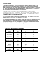
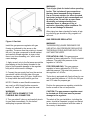
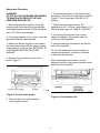
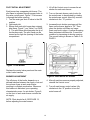
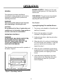
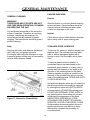
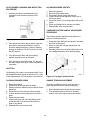
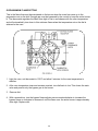
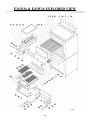
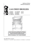
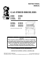
INSTRUCTIONAL MANUAL GAS FIRED BROILERS E36W36 E43W36 E136W36 EV136W36 E236W36 E243W36 EC36 EC45 EC36W36 WC43W36 E136C36 E136C45 EV136C36 EV136C45 W136XC36 W136XC45 with optional searing plate (-SHB) NOTICE: This manual is prepared for the use of Service Technicians and should not be used by those not properly qualified. This manual is not intended to be all encompassing. You should read, in its entirety, the repair procedure you wish to perform to determine if you have the necessary tools, instruments, and skills required to perform the procedure. RETAIN THIS MANUAL FOR FUTURE REFERENCE. DESTINATION COUNTRIES: AUSTRALIA, NEW ZEALAND THE MONTAGUE COMPANY www.montaguecompany.com 1830 Stearman Avenue • P.O. BOX 4954 • HAYWARD,CA 94540-4954 •TEL: 510/785-8822 • FAX: 510/785-3342 IMPORTANT FOR YOUR SAFETY THE INSTALLATION INSTRUCTIONS CONTAINED HEREIN ARE FOR THE USE OF QUALIFIED INSTALLATION AND SERVICE PERSONNEL ONLY. INSTALLATION OR SERVICE BY OTHER THAN QUALIFIED PERSONNEL MAY RESULT IN DAMAGE TO THE UNIT AND/OR INJURY TO THE OPERATOR. IF YOU SMELL GAS 1. TURN OFF THE APPLIANCE AT THE GAS INLET COCK AND OPEN ALL DOORS AND WINDOWS. 2. DO NOT OPERATE ANY ELECTRICAL SWITCHES AND EXTINGUISH ALL NAKED FLAMES. 3. CONTACT THE LOCAL GAS AUTHORITY IMMEDIATELY. THE FOLLOWING INSTRUCTIONS SHOULD BE READ CAREFULLY AS THE MANUFACTURER CANNOT BE HELD RESPONSIBLE FOR ANY DAMAGE TO PROPERTY, PERSONS OR ANIMALS CAUSED BY INCORRECT INSTALLATION OR OPERATION OF THE APPLIANCE. POST IN A PROMINENT LOCATION THE INSTRUCTIONS TO BE FOLLOWED IN THE EVENT THE SMELL OF GAS IS DETECTED. THIS INFORMATION CAN BE OBTAINED FROM THE LOCAL GAS SUPPLIER. IN THE EVENT OF POWER FAILURE, DO NOT ATTEMPT TO OPERATE THIS DEVICE. IMPORTANT IN THE EVENT A GAS ODOR IS DETECTED, SHUT DOWN UNITS AT MAIN SHUTOFF VALVE AND CONTACT THE LOCAL GAS COMPANY OR SUPPLIER FOR SERVICE. FOR YOUR SAFETY DO NOT SPRAY AEROSOLS, STORE OR USE GASOLINE OR OTHER FLAMMABLE VAPORS OR LIQUIDS IN THE VICINITY OF THIS APPLIANCE WHILE IN OPERATION. WARNING! Improper installation, adjustment, alteration, service, or maintenance can cause property damage, injury, or death. Read the INSTALLATION AND OPERATING INSTRUCTIONS thoroughly before installing, servicing, or operating this equipment. SAVE THESE INSTRUCTIONS FOR FUTURE USE. 2 TABLE OF CONTENTS IMPORTANT FOR YOUR SAFETY INTRODUCTION GENERAL MODELS ………. 4 ………. 4 DATA PLATE LOCATION ………. 4 SERIAL NUMBER LOCATION RECEIVING AND INSPECTING THE EQUIPMENT SPECIFICATIONS INSTALLATION ………. 4 ………. 4 STATUTORY REGULATIONS CLEARANCES ………. 6 ………. 6 ………. 5 ………. 6 VENTILATING HOOD ………. 6 VENTILATION AIR ASSEMBLY ………. 6 ………. 6 Legs ELECTRICAL CONNECTION ………. 6 7 Ceramic Radiants LOCATION ………. 8 ………. 8 SITING BATTERY ARRANGEMENT ………. 8 ………. 8 Setting in Place ………. 8 Floor Mounted Ranges GAS SUPPLY ………. 9 ………. 9 GAS CONNECTION GAS PRESSURE REGULATOR ………. 9 ………. 10 Adjustment Procedure PILOT INITIAL ADJUSTMENT ………. 11 ………. 12 BURNER ADJUSTMENT ………. 12 OPERATION GENERAL OPERATING CONTROLS Gas Control C36 & C45 EXPLODED VIEW C36 & C45 PARTS LIST 36W36 & 43W36 EXPLODED VIEW 36W36 & 43W36 PARTS LIST Montague E136 Series Heavy Duty Range Parts List PARTS REMOVAL AND REPLACEMENT PROCEDURES COVERS AND PANELS Venturi Cover Control Panel Cover DRIP DEFLECTOR PILOT ASSEMBLY AND INJECTOR MAIN BURNER Burner Assembly, Orifice, and Venturi Burner Valve Removal/Replacement CARRIAGE POSITION HANDLE Black Ball Knob Chrome Sleeve Threaded Stud Gear and Tube Assembly Compression Spring Gear with Bracket SERVICE AND ADJUSTMENT PROCEDURES GAS PRESSURE REGULATOR ADJUSTMENT PROCEDURE PILOT BURNER CLEANING AND ADJUSTMENT PROCEDURE GAS TAPS CLEANING BURNER HEADS CLEANING BURNER VENTURI CARRIAGE POSITION HANDLE ADJUSTMENT PROCEDURE Handle Tension Adjustment CARRIAGE TENSION SPRING ADJUSTMENT PROCEDURE MISCELLANEOUS SAFETY AND PILOT BURNER INSPECTION SAFETY PILOT VALVE OVEN PILOT BURNER OPERATIONAL DIFFICULTIES & PROBABLE CAUSES TROUBLESHOOTING CHART EC36 & E45 EXPLODED VIEW EC36 & E45 PARTS LIST E36W36 & E43W36 EXPLODED VIEW E36W36 & E43W36 PARTS LIST Montague E136 Series Heavy Duty Range Parts List ………. 2 ………. 4 ………. 15 ………. 15 ………. 16 ………. 15 Lighting/Relighting Pilot and Main Burner ………. 15 Shutdown ………. 16 Grid Height Adjustment GENERAL MAINTENANCE ………. 16 ………. 18 GENERAL CLEANING ………. 18 Daily PAINTED SURFACES ………. 18 ………. 18 Exterior Interior ………. 18 ………. 18 STAINLESS STEEL SURFACES VENTILATION ………. 18 ………. 19 SERVICING SAFETY ………. 19 ………. 19 3 ………. 20 ………. 21 ………. 22 ………. 23 ………. 24 ………. 27 ………. 27 ………. 27 ………. 27 ………. 28 ………. 29 ………. 30 ………. 31 ………. 31 ………. 32 ………. 32 ………. 32 ………. 32 ………. 32 ………. 33 ………. 33 ………. 33 ………. 33 ………. 34 ………. 34 ………. 34 ………. 34 ………. 34 ………. 34 ………. 35 ………. 35 ………. 36 ………. 36 ………. 36 ………. 37 ………. 38 ………. 39 ………. 40 ………. 42 ………. 43 ………. 46 INTRODUCTION GENERAL MODEL: The gas broilers covered in this manual are manufactured for use with the type of gas indicated on the nameplate. Some models include a cabinet, conventional oven or convection oven. Ovens are covered in separate manuals. This manual only covers the broiler. SERIAL NO.: SUPPLY PRESSURE: mbar Montague gas broilers are produced with the best possible material and workmanship. Proper installation is essential for safe, efficient, troublefree operation. GAS: mbar HEAT INPUT: CATEGORY: SET PRESS: ELECTRICAL V MODELS MODEL kW Hz Ph W COUNTRY: P.I.N: CONSISTS OF 0359-10 GAS CATERING EQUIPMENT SALAMANDER– TYPE A E36W36 E43W36 Cabinet Base Broiler with Warming Oven EV136W36 E136W36 Broiler with Conv. or Std. Oven + Warming Oven (opt. ‗W45) EV136C36 E136C36 Broiler with Convection or Standard Oven (opt. ‗C45) RECEIVING AND INSPECTING THE EQUIPMENT E136XC36 Broiler w/ Low Oven (opt. ‗C45) E236W36 Double Broiler (opt. E243W36) Care should be taken during unloading so the equipment is not damaged while being moved into the building. THE MONTAGUE COMPANY HAYWARD, CALIFORNIA USA Figure 1. Typical Nameplate EC36 Broiler w/ Stand (opt. EC45) 1. Visually inspect the exterior of the package and skid or container. Any damage should be noted and reported to the delivering carrier immediately. EC36W36 Double Broiler + Warming Oven 2. If damaged, open and inspect the contents with the carrier. EC45W36 Double Broiler + Warming Oven Note: A suffix of ―SHB‖ designates searing plate option. 3. In the event that the exterior is not damaged, yet upon opening, there is concealed damage to the equipment, notify the carrier. Notification should be made verbally as well as in written form. DATA PLATE LOCATION The Data Plate is located on the front of the unit, or inside the oven burner. 4. Request an inspection by the shipping company of the damaged equipment. This should be done within 10 days from receipt of the equipment. SERIAL NUMBER LOCATION Always have the serial number of your unit available when calling for parts or service. The serial number is on the nameplate that also includes the model number. A typical identification plate is shown in Figure 1. 5. Freight carriers can supply the necessary damage forms upon request. 6. Retain all shipping materials until an inspection has been made or waived. 4 SPECIFICATIONS Table A: Heat Input MODEL No. Burners (broiler/oven) Natural Gas MJ/h Propane Gas MJ/h TOTAL MJ/h E36W36 2/0 44.3 ea. 44.3 ea. 88.6 E43W36 3/0 44.3 ea. 44.3 ea. 132.9 E136W36 2/1 44.3 / 42.2 ea. 44.3 / 42.2 ea. 130.8 EV136W36 2/1 44.3 / 42.2 ea. 44.3 / 42.2 ea. 130.8 E236W36 4/0 44.3 ea. 44.3 ea. 177.2 E243W36 6/0 44.3 ea. 44.3 ea. 265.8 EC36 2/0 44.3 ea. 44.3 ea. 88.6 EC45 3/0 44.3 ea. 44.3 ea. 132.9 Table B: Setting Pressure/Injector Size Manifold Pressure Orifices Natural: 1.0kPa Propane: 2.75 kPa Fixed for specified gas type Natural: Broiler: 3.05mm Oven: 2.95mm Propane: Broiler: 1.93mm Oven: 1.85mm Gas Inlet Size: 3/4‖ NPT at lower left rear (all models) NOTE: The pressure must be measured at the pressure test nipple located at the manifold pipe with the burner lit. TABLE C: Aeration Shutter/Pilot Flame Settings MODEL Natural Gas Broiler/Oven mm Propane Broiler/Oven mm PILOT FLAME LENGTH mm E36W36 25 / — 32 / — 12.5 E43W36 25 / — 32 / — 12.5 E136W36 25 / 19 32 / 22 12.5 EV136W36 25 / 19 32 / 22 12.5 E236W36 25 / — 32 / — 12.5 E243W36 25 / — 32 / — 12.5 EC36 25 / — 32 / — 12.5 EC45 25 / — 32 / — 12.5 5 INSTALLATION THIS APPLIANCE, WHEN INSTALLED, MUST BE ELECTRICALLY GROUNDED IN ACCORDANCE WITH LOCAL CODES. THIS APPLIANCE MUST BE INSTALLED WITH THE REQUIREMENTS OF AS5601 / AG601, LOCAL AUTHORITY, GAS, ELECTRICITY AND ANY OTHER RELEVANT STATUTORY REGULATIONS. CAUTION: Provision must be made to assure adequate air supply to unit for proper burner operation. NOTE 1: The room containing the appliance is required to have a permanent air vent. The minimum effective area of the vent is related to the maximum rated hear input of the appliance and shall be 4.5 cm² per kW in excess of 7kW. STATUTORY REGULATIONS The installation of this appliance must be carried out by a competent person in accordance with the relevant regulations, standards, codes of practice, and the related publications of the country of destination. NOTE 2: Air vents should be of such a size to compensate for the effects of any extract fan in the premises. CLEARANCES The following are minimum clearances from combustible and noncombustible materials. Location Combustible Construction Noncombustible Construction Back Wall 152 mm 0 mm Left Side 152 mm 0 mm Right Side 152 mm 0 mm It is also necessary that sufficient room air ingress be allowed to compensate for the amount of air removed by the ventilating system. Otherwise, a subnormal atmospheric pressure will occur which may interfere with burner performance or may extinguish the pilot flame. In case of unsatisfactory broiler performance, check with the exhaust fan in the ―OFF‖ position. This appliance is to be installed with sufficient ventilation to prevent the occurrence of unacceptable concentrations of substances harmful to health in the room in which it is installed. 1000mm clearance above to combustibles. With 152mm legs: Suitable for installation on combustible floors. ASSEMBLY Without legs: For use with special insulated base on noncombustible floors only. Uncrate broiler as near to final location as possible. For easier and lighter handling of broiler, remove grids, grid frame, drip tray and grease container. Remove all packing materials and accessories from broiler interior. The EV 136 must have an air space behind it. VENTILATING HOOD The broiler(s) must be installed under a properly designed ventilating hood. The hood should extend at least 152mm beyond all sides of the unit. The hood should be connected to an adequate mechanical exhaust system. Legs VENTILATION AIR 2. Tightly screw the complete leg assembly into the mounting holes in the bottom of the broiler at each corner. If the unit is intended for curb installation, no legs are provided. The curb must be noncombustible material. Some broilers are mounted on legs. 1. Screws the legs into the modular stand. The following notes are intended to give general guidance. For detailed recommendations, refer to the applicable code(s) in the country of destination. THE GAS CONNECTION IS LOCATED 813mm ABOVE THE FINISHED FLOOR AND 127mm FROM THE LEFT SIDE ON THE REAR OF THE UNIT 6 Electrical Connection A terminal block is provided for 208-240 VAC equipment. The wiring diagram is located on the back of the range. To connect supply wires, remove cover from connection box at right rear of range. Route supply wires and ground wire through hole with strain relief fitting at top of connection box. Attach supply wires to proper terminal of terminal block. Attach ground wire to ground loug inside connection box. See wiring diagram for proper connection. THIS APPLIANCE, WHEN INSTALLED, MUST BE ELECTRICALLY GROUNDED IN ACCORDANCE WITH LOCAL CODES. THIS APPLIANCE MUST BE INSTALLED WITH THE REQUIREMENTS OF AS5601 / AG601, LOCAL AUTHORITY, GAS, ELECTRICITY, AND ANY OTHER RELEVANT STATUTORY REGULATIONS. THE ELECTRICAL CONNECTION IS LOCATED 254mm ABOVE THE FINISHED FLOOR AND 305mm FROM THE RIGHT SIDE ON THE REAR OF THE UNIT. The installation of electrical wiring from the electric meter, main control box, or service outlet to the electric appliance must be performed by a licensed electrician. Qualified installation personnel must be experienced with such work, be familiar with all precautions required and have complied with all requirements of state or local authorities having jurisdiction. OVERALL DIMENSIONS (in millimetres): Model Height Width Depth E36W36 1816 914 933 E43W36 1816 1143 933 E(V)136W36 1816 914 933 E(V)136C36 1451 914 933 E(V)136C45 1451 1143 933 E136XC36(SHB) 1426 914 870 E136XC45(SHB) 1426 1143 870 E236W36 1603 914 870 E243W36 1603 1143 870 EC36(SHB) 1324 914 870 EC45(SHB) 1324 1143 870 EC36W36 1968 914 864 EC43W36 1968 1143 864 7 Ceramic Radiants Ceramic radiants, Figure 2, are located on each side of the burners. Ceramic end pieces are installed at both ends of each burner assembly. Five (5) ceramic radiants are installed on each side of the burner with the pointed side facing down and the side holes facing up, Figure 3. 2. Tilt ceramic radiants sideways to clear burner and frame assembly, then lower radiant into position with one flange resting on burner ledge and one flange resting on frame edge. 3. Install the remaining ceramic radiants so that five (5) ceramic radiants are located on each side of the burner. LOCATION Adequate clearance for service and proper operation must be provided at the front, top, sides, and back. The combustion air openings are provided in the front of the unit and must not be obstructed. SITING The floor on which the range is to be sited must be capable of adequately supporting the weight of the appliance and any ancillary equipment. Once in position, check that the unit is level, both front to back and side to side. Adjust if necessary, using the adjusting foot on each leg. Figure 2. Ceramic Radiants Positioning BATTERY ARRANGEMENT Carefully remove range from crate. Burner tie wires and other packing materials must be removed from the unit. On stainless steel units, the protective material covering the stainless steel must be removed immediately after unit is installed. Setting in Place Figure 3. Ceramic Radiants Model Nos. E36W36, E43W36, E136W36 and EV136W36. 1. Insert ceramic end pieces at front and rear of the burner frame. Four (4) are required for each burner. 8 All fixed (non-mobile) appliances MUST be fitted with a manual gas cook upstream of the appliance to provide a means of isolation for servicing and cleaning. A union or similar means of disconnection must be provided between the gas cook and the appliance. Floor Mounted Ranges 1. Place the first unit in the exact position it will occupy in the battery. 2. Using a carpenter‘s level, level the unit frontto-rear and side-to-side. AN UNLEVELED UNIT WILL ADVERSELY AFFECT PERFORMANCE. Adjust as follows: A manually operable valve must be fitted to the gas supply to the kitchen to enable it to be isolated in an emergency. Wherever practical, this shall be located either outside the kitchen or near an exit in a readily accessible position. FLOOR INSTALLATION ON LEGS: Level by turning foot on leg. Where it is not practical to do this, an automatic isolation valve system shall be fitted which can be operated from a readily accessible position near the exit. CURB INSTALLATION: Place shim under the low side. This operation is important since variations in floors and curbs are common. Unless units are level, aligning the gas supply manifold will be difficult and the units will not fit together tightly. At locations where the manual isolation valve is fitted or the automatic system can be reset, a notice MUST be fitted, stating: 3. Remove the valve panel from the broiler. 4. Move the next unit into position. “ALL DOWNSTREAM BURNER AND PILOT VALVES MUST BE TURNED OFF PRIOR TO ATTEMPTING TO RESTORE THE SUPPLY. AFTER EXTENDED SHUT OFF, PURGE BEFORE RESTORING GAS.” 5. Engage union nut on manifold with male fitting on next unit and draw up union nut hand tight. Be sure appliances meet together both front and rear. If manifolds do not align, then units are not level. In extreme cases, it may be necessary to loosen manifold bolts and adjust. GAS CONNECTION Before connecting the broiler(s) to the gas supply line, be sure that all new piping has been cleaned and purged to prevent any foreign matter from being carried into the controls by the gas. In some cases, filters or drops are recommended. A separate gas shutoff valve must be installed upstream from the gas pressure regulator adjacent to the broiler and located in an accessible area. 6. Continue leveling and connecting gas supply manifolds together until all appliances in battery are connected. 7. Tighten manifold gas union. Use backup wrench to prevent manifold from rotating. FAILURE TO DO THIS MAY RESULT IN DAMAGE TO THE PILOTS AND GAS VALVES. It is important that adequately sized piping be run directly to the point of connection at the broiler with as few elbows and tees as possible. Consult your local gas company for proper piping size and gas pressure. Each broiler has a 3/4" NPT manifold input located at the lower left rear of the broiler, Figure 4. On dual broilers, each broiler must have a separate regulator. GAS SUPPLY The local gas region should be consulted at the installation planning stage in order to establish the availability of an adequate supply of gas and to ensure that the meter is adequate for the required flow rate. The pipe work from the meter to the appliances must be of appropriate size. Where a number of appliances are installed in a battery, no more than five should be served by any one supply pipe. NOTE: Pipe joint compound or thread sealant that is used should be resistant to action of liquefied petroleum gases. 9 WARNING! Test all pipe joints for leaks before operating broiler. This includes all gas connections that may have loosened during shipment. Use a rich soap solution (or other accepted leak tester) around all pipe connections and all other joints. Do not use an open flame. Absolutely no leakage should occur, otherwise there is a danger of fire or explosion depending upon conditions. Do not use unit leakage is detected. After piping has been checked for leaks, all piping receiving gas should be fully purged to remove air. GAS PRESSURE REGULATOR Figure 4. Gas Inlet WARNING! THE BROILER(S) IS/ARE DESIGNED FOR USE WITH A GAS PRESSURE REGULATOR. THE REGULATOR(S) SUPPLIED WITH THIS UNIT MUST BE USED. Install the gas pressure regulator with gas flowing as indicated by the arrow on the regulator. The arrow must be pointing in toward the unit. Use pipe compound or thread sealant and carefully thread regulator to pipe so that there is no cross threading, etc., which could cause leakage. FOR NATURAL GAS: This gas pressure regulator is factory adjusted for 1.0 kPa manifold pressure. The rated inlet pressure to the regulator is 3.45 kPa. 1. Apply wrench only to the flat areas around the pipe tapping at the end being threaded to the pipe to avoid possible damage to the regulator body which could result in leakage. FOR PROPANE GAS: This gas pressure regulator is factory adjusted for 2.75 kPa manifold pressure. The rated inlet pressure to the regulator is 3.45 kPa. 2. Connect the gas supply line from the service gas shutoff valve to the inlet side of the gas pressure regulator using 3/4" pipe. Avoid kinks or sharp bends that could restrict gas flow. The broiler is equipped with fixed orifices for use with a manifold pressure of 1.0 kPa for G20 gas and 2.75 mbar for propane gas. NOTE: If flexible or semi-flexible connectors are used, an AGA listed flexible connector with an I.D. equal to 3/4" pipe must be used. Position the gas pressure regulator outside the broiler as near to the unit as possible. WARNING! DO NOT USE A DOMESTIC TYPE FLEXIBLE GAS CONNECTOR. CAUTION: The gas pressure regulator must be located out of the heat zone to prevent damage to the regulator. 3. Turn gas shutoff valve on and carefully check for gas leaks immediately. Do this before attempting to operate the broiler. The whole of the gas installation, including the meter, should be inspected, purged, and tested for soundness in accordance with the codes of the country of destination. 10 Adjustment Procedure WARNING! DO NOT ALLOW UNTRAINED PERSONNEL TO MAINTAIN OR SERVICE THE GAS PRESSURE REGULATOR. 6. Connect a manometer to the pressure tap provided on the broiler unit gas piping manifold, Figure 6. Turn all gas taps to the full on ―O‖ position. 1. Before adjusting the regulator, check the incoming gas line pressure into the regulator. Incoming pressure must be 20 kPa for natural gas or 3.5 kPa for propane gas. 7. Check the manometer reading. The reading must be 1.0 kPa for natural gas or 2.75 kPa for propane gas, per Table B on PAGE 5. 8. If incoming line pressure is not correct, adjust the regulator. Remove the seal cap on the top of the regulator. 2. If incoming pressure is not correct, have the gas source checked and adjusted. 3. Make sure that the regulator is mounted in the horizontal position with the arrow pointing in the direction of the gas flow. SEE PAGE 15, LIGHTING/RELIGHTING PILOT AND BURNER. 9. Insert a blade-type screwdriver into the top hole of the regulator. 10. Turn the adjustment screw clockwise to increase the pressure, or counter clockwise to decrease the pressure. 4. Remove the main burner control valve knobs, Figure 5. While watching the manometer, turn the adjustment screw to set proper regulator outlet pressure to the manifold. Figure 5. Control Valve Knobs Figure 6. Gas Pressure Tap 5. Remove the control valve panel by removing two screws. 11 PILOT INITIAL ADJUSTMENT 1. Lift off the Venturi cover to access the air shutter for each main burner. Each burner has a separate pilot burner. The pilot flame is adjusted through access holes in the valve control panel, Figure 7. Pilot access is through the broiler opening. 1. Turn the main gas shut off valve to the ON position. 2. Light each pilot. 3. Ensure that each pilot burner has a steady blue flame, Figure 7, per Table C on PAGE 5. The pilot flame should envelop the tip of the thermocouple. The pilot flame can be viewed up through the opening of the broiler compartment. 2. Turn on the main burner control valve for the main burner to be adjusted by rotating the main burner control valve fully counterclockwise to the ―O‖ position. 3. Increase the air shutter openings until the flame on the burner begins to ―lift‖. Then close the shutter until flame no longer floats, and lock in place. A yellow streaming flame indicates insufficient air. Correct this condition by increasing air shutter opening. The correct setting is shown on Table C on PAGE 5. Figure 7. Pilot Burner Replace the control valve panel and the main control valve handles. BURNER ADJUSTMENT Figure 8. Main Burner Air Shutter The efficiency of the broiler depends on a delicate balance between the supply of air and the volume of gas at each main burner resulting in complete combustion. Whenever this balance is disturbed, poor operating characteristics occur. An air shutter, Figure 8, on the front of each main burner controls the air supply. 4. After all main burners are properly adjusted, reinstall the Venturi cover. 5. Turn all main burner control valves fully clockwise to the ―O‖ position to turn the main burner off. NOTE: Pilots should be lit, SEE PAGE 12, before adjusting the main burners. 12 OVEN MINIMUM FLAME SETTING This is the flame that must be maintained on the burner when the oven has come up to the temperature set on the dial. Enough gas must be bypassed by the control to keep the entire burner lit. The thermostat regulates the flame from high to low in accordance with the oven temperature and will automatically turn down to this minimum flame when the temperature set on the dial is attained in the oven. 1. Light the oven, set thermostat to 100°C and allow 5 minutes for the oven temperature to stabilize. 2. After oven temperature rises and remains constant, turn dial back to low. This closes the main valve and permits only the bypass gas to the burner. 3. Remove dial. 4. With a screwdriver, turn the bypass flame adjustor screw counterclockwise to increase the bypass flame or clockwise to decrease it until the flame over the entire burner is approximately 4mm high. Replace dial. 13 THERMOSTAT CALIBRATION CHECK The calibration of this thermostat should not be changed until considerable experience with cooking results has definitely proved that the thermostat is not maintaining the proper temperature. The recalibration should not be made until the bypass (minimum burner) flame has been properly adjusted. If re-calibration becomes necessary, the following procedure should be followed: 1. 2. 3. 4. Place the thermocouple of test instrument or thermometer in the middle of the oven. Light the main burner. Turn dial to between the ―180‖ and the ―200‖ position (190). Allow the oven to heat until the flames cut down to bypass. After sufficient time, check temperature. If the temperature does not read within 10 degrees of the dial setting, recalibrate as follows: A. Pull dial straight off without turning. B. Hold calibration plate and loosen the two calibration lock screws until the plate can be moved independently of the control. C. Turn calibration plate so that the instrument or thermometer reading is in line with the indi cator mark. Hold plate and tighten screws firmly. Turn the calibration plate counter clockwise if the test reading is higher than the dial setting. Replace dial. NOTE: If the above adjustment is prevented by the two loosened calibration lock screws being in contact with the ends of the screw clearance slots in the calibration plate, remove the screws and after turning the calibration plate to the proper location, reassemble screws in the other tapped holes designed for them. OVEN A. Light pilot in accordance with the Lighting Instructions. B. Check that the length of the pilot flame is correct per table C. All pilot flames should envelop the tip of the thermocouple. The pilot flame can be viewed through the opening in the front of the burner compartment panel. Replace the burner access panel. Hand the Instructions & Operation Manual to the user or purchaser for retention and instruct them in the efficient and safe operation of the appliance. Tell the user of the location of the gas isolation cock for use in an emergency. Leave this manual with the user or purchaser. 14 ` OPERATION BURNER CONTROL: Used to turn the main burner and pilot gas on or off. One control for each burner. GENERAL This appliance has been classified as commercial cooking equipment and must be operated by qualified and/or professional operating personnel. GRID HEIGHT: The grid is set to the desired cooking height by depressing the ball and adjusting the lever up or down. WARNING! The broiler and its parts are hot. Use care when operating or servicing the unit. Gas Control Lighting/Relighting Pilot and Main Burner CAUTION: Do not obstruct the flow of combustion and ventilation air to the broiler. Keep appliance area free and clear of combustibles. 1. Turn burner valve handle to off position and wait five (5) minutes. 2. Push in the tap and turn it counterclockwise to the ignition position. OPERATING CONTROLS WARNING! IN THE EVENT GAS ODOR IS DETECTED, SHUT DOWN UNITS AT MAIN GAS SHUTOFF VALVE AND CONTACT THE LOCAL GAS COMPANY OR GAS SUPPLIER FOR SERVICE. 3. Holding the tap fully in, light the pilot with a match or taper. 4. When the pilot is lit, continue to hold the tap in for 20 seconds, then release it. If the pilot goes out, wait for five (5) minutes, then repeat from step 1. The following controls are used for operation of the broiler, Figure 9. 5. When the pilot is established, push the tap in again and turn it counter-clockwise to the full flame position, thus lighting the main burner. 6. If pilot becomes extinguished, turn main burner valve to the off position (fully counterclockwise) and wait five (5) minutes before relighting. Figure 9. Operating Controls 15 Shutdown, Broiler Preheat, and Grid Height Adjustment 1. Standby: To turn off, rotate main burner valve handles clockwise to the ignition position. 2. Complete: To shut the burner and pilot off, turn the dial to the ―●‖ symbol and the safety device will disengage within 60 seconds. IMPORTANT: NEVER THROTTLE THE BURNER DOWN. OPERATE BURNER IN FULL ON POSITION. PREHEAT TIME— Allow at least five (5) minutes after turning the broiler on from cold, before loading the broiler with food to be cooked. Check the grease container and drain frequently during heavy use to prevent overflow. Grid Height Adjustment Depress black ball and move lever up or down to desired cooking height, Figure 9. 16 OVENS The temperature is automatically controlled by the thermostat so that satisfactory cooking can be repeated. For the best performance, the following instruction should be followed: GRID SHELVES—There are three shelf positions. The shelf position is governed by the size of the product to be cooked. Always push the shelf back into the oven until it stops by making contact with the rear of the oven. TRAY SIZE—A cake tray may be used on each shelf. Single trays or dishes must not be allowed to overhang the shelf in any direction, since this will adversely affect the heat circulation. PREHEAT TIME—Allow at least 30 minutes after turning the oven on from cold, with the thermostat set at the desired temperature before loading the oven with food to be cooked. Put the food in quickly and close the door. LIGHTING THE OVEN To light the oven: 1. Push in the main oven/pilot tap and turn it counter-clockwise to the ignition position. 2. Holding the tap in fully, depress the ignitor button and observe that the pilot lights. If it does not, repeatedly depress the ignitor button until it does. 3. When the pilot is lit, continue to hold the tap fully in for 20 seconds, then release it. If the pilot goes out, wait for five (5) minutes then repeat from step 1. 4. When the pilot is established, push the tap again and turn it counter-clockwise to the full flame position ―260°C‖. Then the set thermostat to the desired temperature. 5. To shut the burner off, turn the dial to the ―●‖ position and the safety device will disengage within 60 seconds. 17 GENERAL MAINTENANCE PAINTED SURFACES GENERAL CLEANING Exterior WARNING! THE BROILER AND ITS PARTS ARE HOT. USE CARE WHEN OPERATING, CLEANING OR SERVICING THE UNIT. Allow the broiler to cool down before cleaning exterior surfaces. Painted surface should be cleaned using a mild soap and warm water solution on a sponge or soft cloth. Lint and grease suspended in the air tend to collect in passages. Therefore, air openings, flueways, and primary air openings, etc., should be periodically cleaned to prevent clogging. The entire broiler should be given a periodic cleaning. Interior Clean interior using a mildly abrasive cleanser with a damp cloth or nylon cleaning pad. Daily STAINLESS STEEL SURFACES Remove grid racks, drip deflector (below grid rack), drip tray, and grease container. Thoroughly wash with mild detergent or soap. Excessive grease buildup may be removed by using a mildly abrasive cleaner. To remove dirt, grease or product residue from stainless steel, use ordinary soap and water (with or without detergent) applied with a sponge or cloth. Dry thoroughly with a clean cloth. To remove grease and food splatter, or condensed vapors that have baked on the equipment, apply cleanser to a damp cloth or sponge and rub cleanser on the metal in the direction of the polishing lines on the metal. Rubbing cleanser as gently as possible in the direction of the polished lines will not mar the finish of the stainless steel. NEVER RUB WITH A CIRCULAR MOTION. Soil and burnt deposits which do not respond to the above procedure can usually be removed by rubbing the surface with SCOTCH-BRITE scouring pads or STAINLESS scouring pads. DO NOT USE ORDINARY STEEL WOOL as any particles left on the surface will rust and further spoil the appearance of the finish. NEVER USE A WIRE BRUSH, STEEL SCOURING PADS (EXCEPT STAINLESS), SCRAPER, FILE OR OTHER STEEL TOOLS. Surfaces which are marred collect dirt more rapidly and become more difficult to clean. Marring also increases the possibility of corrosive attack. Figure 11. Items to be Cleaned Daily 18 To remove heat tint: Darkened areas sometimes appear on stainless steel surfaces where the area has been subjected to excessive heat. These darkened areas are caused by thickening of the protective surface of the stainless steel and are not harmful. Heat tint can normally be removed by the procedures described above. Heat tint which does not respond to this procedure calls for a vigorous scouring in the direction of the polish lines, using SCOTCH-BRITE scouring pads or a STAINLESS scouring pad in combination with a powdered cleanser. Heat tint action may be lessened by not applying or by reducing heat to equipment during slack periods. WARNING! If not installed, operated, and maintained in accordance with the manufacturer’s instructions, this product could expose you to substances in fuel or in fuel combustion which can cause death or serious illness, and which are known to the State of California to cause cancer, birth defects, or other reproductive harm. WARNING! All personnel in the workplace who may be subject to any exposure of carbon monoxide must be warned of such possible exposure. This warning should be conveyed in a manner so that it is clearly understood by the employee, and the employee should be asked if in fact he or she understands the correct method of operation of the equipment and that a risk of exposure exists if the equipment is operated improperly. VENTILATION The area in which the appliance is installed must be adequately ventilated to provide air for combustion, removal of products of combustion and removal of steam, etc. The use of a mechanical extract system should be considered. SERVICING To ensure efficient and safe operation of the appliance, it is recommended that servicing is carried out at regular intervals, the frequency of which will vary depending on the installation conditions and usage (usually once per year is adequate). SERVICERS AND NECESSARY REPLACEMENT PARTS CAN BE OBTAINED BY CONTACTING: Servicing must be carried out by competent persons in accordance with the law. HAVERICK MEATS PO BOX 13 13-15 GREEN STREET BANKSMEADOW NSW 2019 AUSTRALIA SAFETY It is essential that the instructions in this booklet are strictly followed for the safe and economical operation of the equipment. If it is known or suspected that a fault exists on the appliance, then it must not be used until the fault has been rectified by a competent person. TEL: +61 2 9316 8900 FAX: +61 2 9316 6034 EMAIL: [email protected] 19 C36 & C45 EXPLODED VIEW 20 ITEM 1 2 3 4 5 6 7 7A 8 PART NUMBERS C36 C45 236W36 243W36 2033-8 2033-8 3504-1 3504-1 1600-4 1600-4 N/A 1602-0 1601-2 1601-2 43476-0 43476-0 11611-4 11611-4 28387-8 11614-9 DESCRIPTION KNOB, BLACK BALL HANDLE, SLEEVE GRID IRON, RIGHT GRID IRON, CENTER GRID IRON, LEFT HANDLE, VALVE CERAMIC, LARGE CERAMIC KIT (10 ea. 11611-4 Large Ceramics, 4 ea. 11614-9 Ceramic 28387-8 Insulators) 11614-9 INSULATOR, CERAMIC 21 22 ITEM PART NUMBERS 1 2 3 4 5 6 7 36W36 2033-8 3504-1 1601-2 N/A 1601-2 43476-0 11611-4 7A 8 9 10 28387-8 11614-9 3173-9 1604-7 DESCRIPTION 43W36 2033-8 3504-1 1601-2 1602-0 1601-2 43476-0 11611-4 KNOB, BLACK BALL SLEEVE GRID IRON, RIGHT GRID IRON, CENTER GRID IRON, LEFT HANDLE, VALVE CERAMIC, LARGE CERAMIC KIT (10 ea. 11611-4 Large Ceramics, 4 ea. 1 1614-9 Ceramic 28387-8 Insulators) 11614-9 INSULATOR, CERAMIC 3173-9 HANDLE 1579-2 WIRE RACK 23 24 25 R 1 R 4 3 R A E 2 BK N WIRE DIAGRAM EV136-AUSTRALIA 240V 50HZ, 1PH ITEM 1 2 3 4 WIRE—TYPE: SIZE 18 GA, 200°C DESCRIPTION SWITCH, FAN MOTOR TERMINAL BLOCK SWITCH, DOOR REPLACEMENT WIRES MUST BE OF SAME TYPE OR EQUIVALENT AS ORIGINAL. 02-13-09 26 REV A 46527-5 PARTS REMOVAL AND REPLACEMENT PROCEDURES Perform the following procedures to remove and replace parts. To eliminate mistakes when ordering parts, always provide the following information: COVERS AND PANELS CAUTION: Turn off the gas supply at the manual shutoff valve that is next to the broiler before attempting to loosen any gas connections. Model Number Serial Number Venturi Cover Removal of the Venturi cover provides access to the air shutter adjustments and main burner orifices. 1. Remove the two screws under the front edge of the Venturi cover. 2. Lift the Venturi cover from the broiler. These numbers are located on the nameplate. CAUTION: Turn off the broiler gas valve and allow broiler to cool before removing any components. THIS APPLIANCE, WHEN INSTALLED, MUST BE ELECTRICALLY GROUNDED IN ACCORDANCE WITH LOCAL CODES. THIS APPLIANCE MUST BE INSTALLED WITH THE REQUIREMENTS OF AS5601 / AG601, LOCAL AUTHORITY, GAS, ELECTRICITY, AND ANY OTHER RELEVANT STATUTORY REGULATION. Figure 1. Venturi Cover Control Panel Cover Removal of the control panel cover provides access to the burner valves, pilot adjustment and carriage springs. 1. Turn the control valves to the full off position, then remove the control valve knobs. 2. Remove the two screws from the front of the control panel. Figure 2. Control Panel Cover 27 DRIP DEFLECTOR DRIP TRAY AND HORIZONTAL GREASE CONTAINER The drip deflector is located below the grid frame and is angled toward the back of the broiler. Grease dripping onto the drip deflector runs off the back edge to the drip tray, then flows forward into the horizontal grease container. The drip tray is located below the drip deflector. Grease dripping onto the drip deflector runs off the back edge to the drip tray then flows forward into the horizontal grease container. 1. Pull the drip tray straight out the front of the broiler. 1. Pull the grid frame assembly forward to the stop. 2. Remove the grids from the frame assembly. 2. Lift the horizontal grease container up and away from the broiler. 3. Lift the back edge of the drip deflector to disengage the drip deflector from the retaining latch. NOTE: When dumping the contents of the horizontal grease container, be sure to follow appropriate regulations for disposing of grease. 4. Slide the drip deflector out at a downward angle. 5. When reinstalling the drip deflector, be sure to engage the front end under the retaining latch. Figure 4. Drip Tray and Grease Container CAUTION: Turn off the gas supply at the manual shutoff valve that is next to the broiler before attempting to loosen any gas connections. Figure 3. Drip Deflector Figure 5. Flame Failure Valve 28 PILOT ASSEMBLY AND INJECTOR The pilot assembly is located adjacent to each burner. The connection for the pilot assembly is accessed through the opening of the broiler compartment. CAUTION: Turn off the gas supply at the manual shutoff valve that is next to the broiler before attempting to loosen any gas connections. Figure 6. Pilot Assembly Connection 1. Remove the Venturi cover as described in COVERS AND PANELS. 2. Disconnect gas line from back of pilot assembly. 3. Unscrew the two nuts attaching the pilot assembly and pilot assembly bracket. NOTE: Check condition of the pilot injector and replace if damaged. 4. Install the new pilot assembly, orifice and pilot assembly bracket. Figure 7. Pilot Assembly 5. Connect the gas line to the back of the pilot assembly. NOTE: Make sure that the pipe joint compound or pipe thread sealant that is being used is resistant to the corrosive actions of liquefied petroleum gases. 6. Turn the main gas shutoff valve to the broiler to the ON position. WARNING! All gas joints disturbed during servicing must be checked for leaks. Check with a soap and water solution (bubbles). DO NOT use an open flame. 7. Light pilot. 8. Reinstall Venturi cover, heat shield, insulation and exterior top. 29 MAIN BURNERS 9. Reassemble by reversing procedure. WARNING! All gas joints disturbed during servicing must be checked for leaks. Check with a soap and water solution (bubbles). DO NOT use an open flame. Figure 9. Orifice Assembly The connection for the burners is accessed by removing the Venturi cover. The burners are accessed by removing the grids and carriage. The burner valves are accessed by removing the control panel cover. CAUTION: Turn off the gas supply at the main shutoff valve that is next to the broiler before attempting to loosen any gas connections. Burner Assembly, Orifice, and Venturi 1. Remove the Venturi cover as described in COVERS AND PANELS. 2. Remove the ceramic radiants from each side of the main burner to be replaced. 3. Loosen the set screw that attached the main burner to the Venturi assembly. 4. Slide the main burner out of the broiler. 5. If the Venturi or orifice is to be replaced, disconnect the gas input to the Venturi. Remove the gasket. Replace the gasket every time the Venturi or burner is removed. 6. Loosen the lock nut so that the Venturi can be removed from the bracket. Burner Valve Removal/Replacement The burner valves are located on the manifold behind the control panel cover. CAUTION: Turn off the gas supply at the manual shutoff valve that is next to the broiler before attempting to loosen any gas connections. 1. Remove the control panel cover as described under COVERS AND PANELS to access the burner valve. 2. Disconnect the gas line, pilot line, and thermocouple from the back of the burner valve. 3. Unscrew the burner valve from the manifold. 4. Install the new burner valve. NOTE: Make sure that the pipe joint compound or pipe thread sealant that is being used is resistant to the corrosive actions of liquefied petroleum gases. Figure 8. Burner pilot assembly 5. Connect the gas line, pilot line, and thermocouple to the back of the valve. 6. Turn the main gas shutoff valve to the broiler to the ON position. 7. Remove the orifice hex nut fitting from the Venturi. 8. Remove the orifice from the hex nut fitting. NOTE: Make sure the pipe joint compound or pipe thread sealant that is being used is resistant to the corrosive actions of liquefied petroleum gases. WARNING! All gas joints disturbed during servicing must be checked for leaks. Check with a soap and water solution (bubbles). DO NOT use an open flame. 30 7. Light pilot (clockwise) onto the threaded stud. Chrome Sleeve 8. Reinstall the control panel cover and control valve knobs. 1. Turn off the burners. 9. Turn burner valve full on and check that burner is properly lit. 2. Allow the broiler to cool to room temperature. 3. Remove the black ball knob by unscrewing it (counterclockwise) from the threaded stud. 4. Remove the sleeve from the tube/threaded stud assembly. 5. Replace the chrome sleeve by placing the s sleeve onto the threaded stud. Threaded Stud Figure 10. Burner Valve 1. Turn off the burners. 2. Allow the broiler to cool to room temperature. CARRIAGE POSITION HANDLE The carriage position handle consists of the parts shown in the following illustration and parts list. 3. Remove the black ball knob by unscrewing it (counterclockwise) from the threaded stud. 4. Remove the chrome sleeve from the tube/ threaded stud assembly. 5. Unscrew the threaded stud from the tube. 6. Reinstall the threaded stud by performing the above steps in reverse order. Screw the threaded stud about 1‖ into the threaded end of the tube. Gear and Tube Assembly Figure 11. Carriage Position Handle 1. Turn off the burners. Item Part No. Description Qty A 02033-8 Knob, Black Ball 1 B 32756-5 Compression Spring 1 C 03503-3 Gear & Tube Assembly 1 D 03506-8 Stud, Threaded 1 E 03504-1 Sleeve, Chrome 1 D 14442-8 Handle Bracket 1 2. Allow the broiler to cool to room temperature. 3. Remove the black ball knob by unscrewing it (counterclockwise) from the threaded stud. 4. Remove the chrome sleeve. 5. Unscrew the threaded stud from the tube. Black Ball Knob 6. Remove gear with bracket from the cabinet frame. 1. Remove the black ball knob by unscrewing it (counterclockwise) from the threaded stud. 7. Slide the gear and tube assembly off the carriage position handle arm. 2. Replace the black ball knob by screwing it 8. Replace the gear and tube assembly by 31 Compression Spring Gear with Bracket 1. Turn off the burners. 1. Turn off the burners. 2. Allow the broiler to cool to room temperature. 2. Allow the broiler to cool to room temperature. 3. Remove the black ball knob by unscrewing it (counterclockwise) from the threaded stud. 3. Raise grill to the top. 4. Remove all components of carriage position handle. 4. Remove the chrome sleeve. 5. Remove the two screws and nuts that hold the gear with bracket to the vertical frame rail. 5. Remove the threaded rod. 6. Remove the spring from the tube and gear assembly using needle nose pliers. 6. Replace the gear with bracket by performing the above steps in reverse order. 7. Replace the compression spring by performing the above steps in reverse order. Figure 12. Gear with Bracket 32 SERVICE AND ADJUSTMENT PROCEDURES Regular maintenance by a competent person is recommended to ensure the continued safe and efficient performance of the appliance. Should service be required, kindly contact your dealer for assistance. Alternately, please contact us at the following address: HAVERICK MEATS PO BOX 13, 13-15 GREEN STREET BANKSMEADOW, NSW 2019 Telephone: +61 2 9316 8900 Fax: +61 2 9316 6034 - info @haverickmeats.com.au WARNING! TURN OFF THE GAS SUPPLY TO THE APPLIANCE AT THE SERVICE COCK BEFORE COMMENCING ANY SERVICING WORK. IMPORTANT: Test for gas soundness on completion of any servicing work. These instructions are intended for use by competent service personnel. GAS PRESSURE REGULATOR ADJUSTMENT PROCEDURE DO NOT allow untrained personnel to maintain or service the gas pressure regulator. Figure 13. Gas Pressure Regulator 1. Before adjusting the regulator, check the incoming gas line pressure. Incoming pressure before the regulator must be 1.0 kPa for natural gas, or 2.75 for propane. 2. If incoming pressure is not correct, have the gas source checked and adjusted as necessary. 3. Make sure that the regulator is mounted in the horizontal position with the arrow pointing in the direction of the gas flow. 4. Connect a manometer to the pressure tap provided on the manifold between the regulator and the burner valves. 5. Check the manometer reading. The reading must be 1.0 kPa for natural gas, or 2.75 kPa for propane. 6. If incoming line pressure is not correct, adjust the regulator. Remove seal cap on top of the regulator. 7. Insert a blade-type screw driver into the top hole of the regulator. 8. Turn the adjustment screw clockwise to increase the pressure, or counterclockwise to decrease the pressure. 9. While watching the manometer, turn the adjustment screw to set proper Regulator outlet pressure. 33 PILOT BURNER CLEANING AND INSPECTION PROCEDURE CLEANING BURNER VENTURI 1. 2. 3. 4. Remove top panel. Remove right control panel. Disconnect injector fitting and remove. Loosen thumb screw and slide Venturi out of the burner head. 5. Clean the Venturi in hot soapy water with a stiff brush. 6. Rinse and shake well to remove any debris. 7. Reassemble in the reverse order. 1. Light the pilot burner as described in the Installation and Operation section of this manual. CARRIAGE POSITION HANDLE ADJUSTMENT PROCEDURE The carriage position handle can be placed in a number of vertical positions. Figure 14. Pilot Burner 1. Grasp the black ball knob and press it in toward the front control panel. 2. Raise or lower the carriage assembly to the desired height. 3. Release pressure on the black ball knob to lock the carriage assembly at the desired height. 2. If the pilot burner flame burns yellow, clean the pilot injector and the pilot burner in order to ensure a steady blue flame. Clean by blowing through or washing. DO NOT use wire to clear the pilot injector. 3. If the pilot burner flame still burns yellow, replace the pilot burner and injector. 4. If the pilot flame does not extend 1/2‖ beyond the outer edges of the pilot, further inspection is necessary. GAS TAPS Re-greasing of the taps is not recommended. If the tap spindles become seized or difficult to turn, refer to the Replacement of Parts section in this manual. Figure 15. Carriage Position Handle CLEANING BURNER HEADS HANDLE TENSION ADJUSTMENT 1. Remove top panel. 2. Remove top liner panel with insulation. 3. Remove ceramic radiants from the burner frame assembly. 4. Remove screw from left end of burner head. 5. Loosen thumb screw holding burner Venturi in place. 6. Remove burner head. 7. Clean the burner with a stiff scrubbing brush and shake well to endure that the ports are clear of any debris. 8. Reassemble in the reverse order. If carriage is difficult to move or will not stay in place, the handle tension requires adjusting. 1. Remove black ball knob and chrome sleeve. 2. Turn threaded knob to the left to increase tension; turn to the right to decrease tension. 34 CARRIAGE TENSION SPRING ADJUSTMENT PROCEDURE MISCELLANEOUS 1. Wire brush the surface of the grid to remove baked on material, wash with hot water, dry thoroughly and reassemble. Carriage Adjustments should be made with the grid irons in place and allowance for product weight. 2. Clean out the grease container and wash with hot soapy water. Dry thoroughly. 3. Wipe exposed cleanable surfaces with a mild detergent and hot water. Stubborn residue may be removed with a lightweight non-metallic scouring pad. Stainless steel areas should be washed with a mild detergent, hot water and a soft cloth. If necessary to use a non-metallic scouring pad, always rub in the direction of the grain in the metal to prevent scratching. NEVER USE STEEL WOOL. Figure 16. Carriage Tension Spring 1. Locate the carriage tension spring adjustment nut. The adjustment nut is accessible from the front as follows: 4. Check the operation of the thermocouple and flame safety devices by lighting the pilot and then blowing it out. Listen for the flame failure valve clicking closed. This action must occur within 60 seconds of extinguishing the pilot. Model Nos. E36W36 and E43W36: Through lower compartment. Model Nos. E136W36 and EV136W36: Behind valve panel. Model Nos. EC36, EC45, E236W36 and E243W36: Behind left and right front panels. 2. Turn nut clockwise to increase tension or counterclockwise to decrease tension. 3. If one side of the grid is lower than the other side, turn the adjustment nut on the low side clockwise to level the grid. 35 OVEN MINIMUM FLAME SETTING This is the flame that must be maintained on the burner when the oven has come up to the temperature set on the dial. Enough gas must be bypassed by the control to keep the entire burner lit. The thermostat regulates the flame from high to low in accordance with the oven temperature and will automatically turn down to this minimum flame when the temperature set on the dial is attained in the oven. 1. Light the oven, set thermostat to 100°C and allow 5 minutes for the oven temperature to stabilize. 2. After oven temperature rises and remains constant, turn dial back to low. This closes the main valve and permits only the bypass gas to the burner. 3. Remove dial. 4. With a screwdriver, turn the bypass flame adjustor screw counterclockwise to increase the bypass flame or clockwise to decrease it until the flame over the entire burner is approximately 4mm high. Replace dial. 36 THERMOSTAT CALIBRATION CHECK The calibration of this thermostat should not be changed until considerable experience with cooking results has definitely proved that the thermostat is not maintaining the proper temperature. The recalibration should not be made until the bypass (minimum burner) flame has been properly adjusted. If re-calibration becomes necessary, the following procedure should be followed: 1. 2. 3. 4. Place the thermocouple of test instrument or thermometer in the middle of the oven. Light the main burner. Turn dial to between the ―180‖ and the ―200‖ position (190). Allow the oven to heat until the flames cut down to bypass. After sufficient time, check temperature. If the temperature does not read within 10 degrees of the dial setting, recalibrate as follows: A. Pull dial straight off without turning. B. Hold calibration plate and loosen the two calibration lock screws until the plate can be moved independently of the control. C. Turn calibration plate so that the instrument or thermometer reading is in line with the indi cator mark. Hold plate and tighten screws firmly. Turn the calibration plate counter clockwise if the test reading is higher than the dial setting. Replace dial. NOTE: If the above adjustment is prevented by the two loosened calibration lock screws being in contact with the ends of the screw clearance slots in the calibration plate, remove the screws and after turning the calibration plate to the proper location, reassemble screws in the other tapped holes designed for them. OVEN A. Light pilot in accordance with the Lighting Instructions. B. Check that the length of the pilot flame is correct per table C. All pilot flames should envelop the tip of the thermocouple. The pilot flame can be viewed through the opening in the front of the burner compartment panel. Replace the burner access panel. Hand the Instructions & Operation Manual to the user or purchaser for retention and instruct them in the efficient and safe operation of the appliance. Tell the user of the location of the gas isolation cock for use in an emergency. Leave this manual with the user or purchaser. 37 ` SAFETY AND PILOT BURNER INSPECTION WHEN SERVICE IS NEEDED, CONTACT A LOCAL SERVICE COMPANY, DEALER, OR FACTORY TO PERFORM MECHANICAL MAINTANACE AND REPAIRS. THESE INSTRUCTIONS ARE INTENDED FOR USE BY COMPETENT SERVICE PERSONNEL. CAUTION: TURN OFF GAS SUPPLY WHEN SERVICING GAS CONTROL SYSTEM. SAFETY PILOT VALVE Model H15HR is an automatic 100% safety pilot which provides complete gas shut off in event of pilot failure. The safety valve is held closed by spring pressure. When red button is pushed by hand, gas flows to pilot. Pilot heats thermocouple creating a very small amount of electricity. This energizes a magnetic coil under the red button and holds valve open, permitting gas to flow to main burner and pilot holding pressure on red button. In the event of pilot failure, the flow of electricity will stop and spring will stop flow of gas to both pilot and oven burner. OVEN PILOT BURNER PILOT SERVICE IN THE EVENT OF PILOT FLAME FAILURE 1. If pilot flame burns yellow, clean pilot orifice and pilot burner to insure a steady blue flame. The P/N 010138 orifice can be cleaned by Pilot Burner washing in a solvent and/or blowing out with air. 2. Flame must surround the thermocouple tip for approximately 1/2 inch. THERMOCOUPLE OUTPUT CLOSED CIRCUIT MV RANGE NORMAL NOT LESS THAN 15-25 8 38 If the closed circuit check shows thermocouple output is greater than 8 millivolts and pilot will not remain lit when the reset button is released, replace safety pilot valve. 3. Thermocouple lead connections must be tight, clean, and free of grease. The thermocouple nut should be started and turned all the way by hand. An additional quarter turn with a small wrench will then be sufficient. CAUTION: OVERTIGHTENING MAY CAUSE DAMAGE TO THE THERMOCOUPLE OR MAGNET AND IS UNNECESSARY SINCE THIS IS AN ELECTRIC CONNECTION. OPERATIONAL DIFFICULTIES & PROBABALE CAUSES OVEN PILOT BURNER GOES OUT: 1. Gas shut off. 2. Poor draft in flue snuffs out flame. 3. Too much draft pulls flame away from thermocouple. 4. Pilot flame too low. 5. Thermocouple defective. 6. Thermocouple connection on safety pilot loose. 7. Pilot orifice dirty. 8. Safety pilot valve defective. 9. Gas leak at pilot orifice fitting. 10. Restricted or plugged vent on gas pressure regulator. OVEN BURNER FAILS TO COME ON (PILOT ON): 1. 2. 3. 4. Burner valve off. Burner orifice plugged. Thermostat out of calibration. Minimum flame adjustment closed and thermostat setting too low. OVEN TEMPERATURE HIGHER THAN DIAL SETTING: 1. 2. 3. 4. Oven thermostat out of calibration. Minimum flame too high. (Do not lower under 1/8‖). Broken capillary tube on thermostat. Dirt under thermostat valve seat. 39 TROUBLESHOOTING CHART SYMPTOM CAUSE REMEDY Pilot burner flames are burning yellow. Gas too rich. Perform the PILOT BURNER CLEANING AND INSPECTION PROCEDURE. Clogged pilot air passages. Perform the PILOT BURNER INJECTOR REMOVAL AND REPLACEMENT PROCEDURE. Low pressure. Check manifold pressure. Clogged pilot burner. Replace pilot burner. Burner flames burning yellow. Incorrect gas pressure or primary air. Check gas pressure. Adjust or clean air mixer. One or more burner flames cannot be adjusted. Dirty Venturi passage. Perform the CLEANING BURNER VENTURI PROCEDURE. Incorrect gas pressure. Check and adjust gas pressure. Ceramics cracked, broken, or missing. Replace damaged or missing ceramics, See Installation & Operation manual. Faulty burner valve. Perform the BURNER VALVE REMOVAL AND REPLACEMENT PROCEDURE. Pilot burner flames are less than or more than 1/2‖. The heat of one or more burners is not uniform over the surface of the ceramic tiles. Carriage assembly will not stay at a set height position. Carriage assembly moves up and down too easily or too hard. Clogged burner ports. Clean burner ports or perform the MAIN BURNER REMOVAL AND REPLACEMENT PROCEDURE. Broken or missing ceramics. Replace broken or missing ceramics. Dirty Venturi passage. Clean air mixer and Venturi. Wrong gas pressure. Check and adjust gas pressure. Improper handle spring tension adjustment. Perform the HANDLE TENSION ADJUSTMENT PROCEDURE. Worn or broken gear with bracket. Perform the GEAR WITH BRACKET REMOVAL AND REPLACEMENT PROCEDURE. Improper carriage spring tension adjustment. Perform the CARRIAGE TENSION SPRING ADJUSTMENT PROCEDURE. 40 EC36 & EC45 EXPLODED VIEW 41 ITEM PART NUMBERS DESCRIPTION EC36 E236W36 EC45 E243W36 1 12925-9 12925-9 PANEL, RIGHT SIDE 2A 25442-8 25442-8 FLUE, RIGHT SIDE 2B 25440-1 25440-1 FLUE, LEFT SIDE 2C 12610-1 15391-5 FLUE DEFLECTOR 3 15355-9 15385-0 EXTERIOR TOP 4 12923-2 12923-2 PANEL, LEFT SIDE 5 42992-9 42992-9 MANIFOLD- FFV 6 43054-4 40566-3 VALVE CONTROL PANEL- FFV 7 42867-1 42867-1 FRAME, BURNER ASSEMBLY 8 26700-7 26700-7 BURNER w/ SET SCREW 9 11614-9 11614-9 INSULATOR, CERAMIC 10 11611-4 11611-4 CERAMIC, LARGE 10A 28387-8 28387-8 11A 15352-4 15383-4 HEAT SHIELD 11B 1430-3 1430-3 INSULATION 12 15182-3 15295-1 FIRE BOX FRONT ASSEMBLY 13A 41741-6 41741-6 PILOT ASSEMBLY w/ SHIELD 13B 26180-7 26180-7 PILOT INJECTOR - Natural Gas 13C 26181-5 26181-5 PILOT INJECTOR - G31 13D 26177-7 26177-7 THERMOCOUPLE - M9X1 X 1500MM 14 3397-9 3397-9 BRACKET, ORIFICE 15 1280-7 1280-7 UNION, TUBING 16 1252-1 1252-1 TUBING, STEEL, 7/16" OD 508MM 17 6378-9 6378-9 BURNER, ORIFICE HEX COMP. FITTING 18A 6150-6 6150-6 ORIFICE– NATURAL GAS 18B 6381-9 6381-9 ORIFICE– PROPANE GAS 19 20923-6 20923-6 GASKET, VENTURI 20 20924-4 20924-4 VENTURI, AIR MIXER ASSEMBLY 21 1224-6 1224-6 TUBING, ALUMINUM - 1/4" OD CERAMIC KIT (10 ea. 11611-4 Large Ceramics; 4 ea. 11614-9 Ceramic Insulators) 42 ITEM 22 PART NUMBERS EC36 EC45 E236W36 E243W36 3396-0 3396-0 DESCRIPTION BEARING, w/ ASSEMBLY 23A 1601-2 1601-2 GRID, WIRE-LEFT; CHROME (PORCELAIN AVAILABLE) 23B N/A 1602-0 GRID, WIRE-CENTER; CHROME (PORCELAIN AVAILABLE) 23C 1600-4 1600-4 GRID, WIRE-RIGHT; CHROME (PORCELAIN AVAILABLE) 24 38331-7 38040-7 GRID FRAME ASSEMBLY 25 15240-4 15328-1 DRIP DEFLECTOR 26 4655-8 4657-4 CARRIAGE ASSEMBLY 27 2033-8 2033-8 KNOB, BLACK BALL 28 3504-1 3504-1 HANDLE, SLEEVE 29 3506-8 3506-8 THREADED ROD 30 3503-3 3503-3 TUBE AND GEAR ASSEMBLY 31 32756-5 32756-5 SPRING, HANDLE 32 14442-8 14442-8 HANDLE ASSEMBLY BRACKET 33 15244-7 15244-7 CARRIAGE SPRING MTG BRACKET 34 1938-0 1938-0 EYE BOLT 35 3507-6 3507-6 GEAR w/ ANGLE BRACKET 36 34258-0 2034-6 CARRIAGE SPRING 37 28365-7 28365-7 CARRIAGE BOLT 38 13096-6 13101-6 STABILIZER UNIT ASSEMBLY 39 43476-0 43476-0 VALVE HANDLE w/o RING 40 40415-2 40415-2 FLAME FAILURE VALVE ASSY 40 43475-2 43475-2 FLAME FAILURE VALVE (NO FITTINGS) 42A 6604-4 6604-4 HORIZONTAL GREASE CONTAINER - PTD 42B 6603-6 6603-6 HORIZIONTAL GREASE CONTAINER - S/S 43 15246-3 15366-4 DRIP TRAY 44 39097-6 40899-9 STAND, MODULAR- S/S 45A 14605-6 14605-6 GAS PRESSURE REGULATOR - NATURAL GAS 45B 1040-5 1040-5 GAS PRESSURE REGULATOR - PROPANE GAS 43 E36W36 & E43W36 EXPLODED VIEW 44 ITEM PART NUMBERS DESCRIPTION E36W36 E43W36 1 15168-8 15287-0 PANEL, BACK AND SIDE 2 15233-1 32069-2 FALSE TOP, REAR 3A 15238-2 32075-7 FLUE, LEFT SIDE 3B 15239-0 32076-5 FLUE, RIGHT SIDE 4 15232-3 15232-3 FALSE TOP, FRONT 5 15609-4 31642-3 DOOR ASSEMBLY 6 3173-9 3173-9 HANDLE 7 15187-4 15305-2 GUARD RAIL ASSEMBLY 8 27394-5 27394-5 VALVE PANEL BRACKET 9 CALL CALL MANIFOLD- FFV 10 42687-1 42687-1 FRAME BURNER ASSEMBLY 11 26700-7 26700-7 BURNER w/ SET SCREW 12 11614-9 11614-9 CERAMIC INSULATOR 13 11611-4 11611-4 CERAMIC, LARGE 13A 28387-8 28387-8 14 15359-1 15359-1 HEAT SHIELD 15 15223-4 31645-8 OVEN BOTTOM LINER 16 1604-7 1579-2 WIRE RACK 17 15182-3 15295-1 FIRE BOX FRONT ASSEMBLY 18A 41741-6 41741-6 PILOT ASSEMBLY W/ SHIELD 18B 26180-7 26180-7 PILOT INJECTOR - NATURAL GAS 18C 26181-5 26181-5 PILOT INJECTOR - PROPANE GAS 18D 26177-7 26177-7 THERMOCOUPLE - M9X1 X1500MM 19 3397-9 26177-7 ORIFICE BRACKET ASSEMBLY 20 1280-7 1280-7 UNION, TUBING 21 1252-1 1252-1 TUBING STEEL - 7/16" OD X 508MM 22 6378-9 6378-9 HEX COMP. FITTING ASSEMBLY 23A 6150-6 6150-6 ORIFICE - NATURAL GAS 23B 6381-9 6381-9 ORIFICE - PROPANE GAS 24 20923-6 20923-6 GASKET, VENTURI CERAMIC KIT (10 ea. 11611-4 Large Ceramics; 4 ea. 11614-9 Ceramic Insulators) 45 ITEM PART NUMBERS DESCRIPTION E36W36 E43W36 25 20924-4 20924-4 VENTURI, AIR MIXER ASSY 26 1231-9 1231-9 TUBING, ALUMINUM 27A 1601-2 1601-2 GRID, WIRE-LEFT; CHROME (PORCELAIN AVAILABLE) 27B N/A 1602-0 GRID, WIRE-CENTER; CHROME (PORCELAIN AVAILABLE) 27C 1601-2 1601-2 GRID, WIRE-RIGHT; CHROME (PORCELAIN AVAILABLE) 28 3396-0 3396-0 BEARING ASSEMBLY 29 32376-4 38040-7 GRID FRAME ASSEMBLY/BEARING 30 15240-4 15328-1 DRIP DEFLECTOR 31 4660-4 4661-2 CARRIAGE ASSEMBLY 32 2033-8 2033-8 KNOB, BLACK BALL 33 3504-1 3504-1 SLEEVE 34 3506-8 3506-8 THREADED ROD 35 3503-3 3503-3 TUBE AND GEAR ASSEMBLY 36 23753-1 23753-1 SPRING, HANDLE 37 14442-8 14442-8 HANDLE ASSEMBLY BRACKET 38 15244-7 15244-7 BRACKET, CARRIAGE SPRING 39 1938-0 1938-0 EYE BOLT 40 34258-0 2034-6 CARRIAGE SPRING 41 3507-6 3507-6 GEAR, w/ ANGLE BRACKET 42 28365-7 28365-7 CARRIAGE BOLT 43 13108-3 13109-1 STABILIZER UNIT ASSEMBLY 45 40415-2 40415-2 FLAME FAILURE VALVE ASSY 45 43475-2 43475-2 FLAME FAILURE VALVE (NO FITTINGS) 46 CALL CALL PANEL, VALVE CONTROL 47 43476-0 43476-0 VALVE HANDLE W/O RING 48A 14605-6 14605-6 REGULATOR, GAS PRESSURE - NATURAL GAS 48B 1040-5 1040-5 REGULATOR, GAS PRESSURE - PROPANE GAS 49 4291-9 4291-9 GREASE DRAWER, 14" x 26 1/2" x 4" 46 47 Item 1 1 1 1 2 2 3 4 5 6 6 7 7 8 9 10 11 12 13 13 13A 13A1 14 15 16 17 18 19 20 21 22 23 24 25 26 26 27 28 28 29 29 30 31 32 32 33 34 35 36 37 38 39 40 41 42 43 44 44 45 46 47 48 49 50 51L 51R 52 52 53 53 54 54 55 56 57 ………. ………. ………. ………. ………. ………. ………. ………. ………. ………. ………. ………. ………. ………. ………. ………. ………. ………. ………. ………. ………. ………. ………. ………. ………. ………. ………. ………. ………. ………. ………. ………. ………. ………. ………. ………. ………. ………. ………. ………. ………. ………. ………. ………. ………. ………. ………. ………. ………. ………. ………. ………. ………. ………. ………. ………. ………. ………. ………. ………. ………. ………. ………. ………. ………. ………. ………. ………. ………. ………. ………. ………. ………. ………. ………. Part # 8955-9 7644-9 6134-4 6135-2 1548-2 2428-7 1424-9 3173-9 2004-4 3566-1 4576-4 1056-1 4490-3 1288-2 6137-9 1073-1 6860-8 4285-4 1547-4 9051-4 4387-7 7987-4 4601-9 6593-5 9044-1 9043-3 1538-5 12874-0 12894-5 7223-0 1942-9 1536-9 6149-2 1013-8 2190-3 2191-1 6155-7 1017-0 1018-9 6150-6 6151-4 3604-8 3602-1 2412-0 1015-4 2037-0 6350-9 9518-4 34604-7 1277-7 1061-8 1977-1 1287-4 3600-5 1150-9 3605-5 3459-2 3524-6 1260-2 6077-1 6979-8 3393-6 4274-9 4275-7 6346-0 6348-7 4645-0 4610-8 4288-9 4286-2 3468-1 3467-3 9005-0 6926-4 7584-1 ………. ………. ………. ………. ………. ………. ………. ………. ………. ………. ………. ………. ………. ………. ………. ………. ………. ………. ………. ………. ………. ………. ………. ………. ………. ………. ………. ………. ………. ………. ………. ………. ………. ………. ………. ………. ………. ………. ………. ………. ………. ………. ………. ………. ………. ………. ………. ………. ………. ………. ………. ………. ………. ………. ………. ………. ………. ………. ………. ………. ………. ………. ………. ………. ………. ………. ………. ………. ………. ………. ………. ………. ………. ………. ………. Description Door Panel, Ext. - ptd (w/ nameplate) Door Panel, Ext. - S/S (w/ nameplate) Door Panel, Ext. - ptd (w/ embossed "M") Door Panel, Ext. - S/S (w/ embossed "M") Door Panel, Int., (prior 8/84) Door Panel, Int., (post 8/84) Insulation, Door Handle, Door Handle, Main Oven Valve Valve Panel - 36" S/S (specify width) Valve Panel - 34" S/S (frytop models only) Valve, Oven - 1/4" NPTM x 7/16" cc (new style) Valve, Oven - 9/16"-27 x 7/16" cc (old style) Pilot Fitting - 1/8" NPT x 1/4" tube Bracket, Valve Panel Manifold - 36", Comb. (order by length & model) Guard Rail - 36", S/S (post 1/85- consult factory) Manifold Drip Shield (specify length) Oven Bottom - Porcelain (change #17) Oven Bottom - Porcelain (change #18) Oven Bottom- Cast Iron (sold as pair) Heat Deflector for 13A bottom Heat Deflector Burner Baffle, S/S Side Liner, Oven - Right (change #18) Side Liner, Oven - Left (change #18) Top Liner, Oven - Porcelain Interior Liner - Left & Right (with stiffener) Insulation, Oven - Left, Right & Rear Rack Guide - Left or Right Clip, Thermostat Bulb Rear Liner, Oven - Porcelain Bracket, Orifice Fitting - Oven Thermocouple Please Order by # and Des. Orifice, Oven Pilot (Nat. Gas) Orifice, Oven Pilot (LP Gas) Compression Nut & Ferrel - 1/4" tube Pilot Burner (Nat. Gas) Pilot Burner (LP Gas) Orifice, Main Burner (Nat. Gas) Orifice, Main Burner (LP Gas) Tubing - 1/4" (safety valve to pilot burner) Tubing - 7/16" (thermostat to burner - 42") Elbow Assembly w/ Orifice (Nat. Gas) Elbow Assembly w/ Orifice (LP Gas) Air Mixer, Oven Burner Burner, Oven (new style less pilot mount) Baffle, Main Oven Burner Safety Valve, Pilot Fitting - 1/4" tube (tapered, compression) Thermostat, FDTO (with dial 500) Dial, FDTO Thermostat Fitting 3/8" NPT x 7/16" tube Tubing 7/16" (main valve to safety - change #8) Nipple, Pipe - 3/8" x 2" Tubing 1/4" (manifold to safety valve) Panel, Firebox - Ptd (change #14- clip style) Panel, Firebox - S/S (change #14- clip style) Spacer, Door Pin Door Trunnion- Right Door Trunnion- Left Pin, Oven Door Door, Pilot Access Burner Compartment Front Baffle, Air - Left Baffle, Air - Right Panel, Right Front Control - Ptd (after 9/70) Panel, Right Front Control - S/S (after 9/70) Panel, Left Front Control - Ptd (after 9/70) Panel, Left Front Control - S/S (after 9/70) Leg - 6" Ptd Leg - 6" S/S Rack , Oven - 25 5/8" x 26" Catch, Spring (female) Support, Channel 48 WARNING! If not installed, operated, and maintained in accordance with the manufacturer’s instructions, this product could expose you to substances in fuel or in fuel combustion which can cause death or serious illness and which are known to the State of California to cause cancer, birth defects, or other reproductive harm. WARNING! All personnel in the work place who may be subject to any exposure of carbon monoxide mist be warned of such possible exposure. This warning should be conveyed in a manner so that it is clearly understood by the employee, and the employee should be asked if in fact he or she understands the correct method of operation of the equipment and that a risk of exposure exists if the equipment is operated improperly. 49 SAVE THESE INSTRUCTIONS FOR FUTURE USE. The Montague Company 1830 Stearman Avenue P.O. Box 4954 Hayward, CA 94540-4954 WWW.MONTAGUECOMPANY.COM 50 P/N 47318-9RC