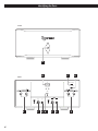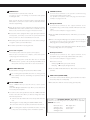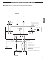
1
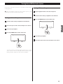
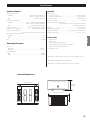
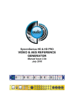
D01145620A
A-02
Power Amplifier
OWNER’S MANUAL
CAUTION: TO REDUCE THE RISK OF ELECTRIC SHOCK, DO NOT
REMOVE COVER (OR BACK). NO USER-SERVICEABLE PARTS
INSIDE. REFER SERVICING TO QUALIFIED SERVICE PERSONNEL.
The lightning flash with arrowhead symbol, within an
equilateral triangle, is intended to alert the user to the
presence of uninsulated “dangerous voltage” within the
product’s enclosure that may be of sufficient magnitude
to constitute a risk of electric shock to persons.
The exclamation point within an equilateral triangle is
intended to alert the user to the presence of important
operating and maintenance (servicing) instructions in the
literature accompanying the appliance.
IMPORTANT SAFETY INSTRUCTIONS
1) Read these instructions.
2) Keep these instructions.
3) Heed all warnings.
4) Follow all instructions.
5) Do not use this apparatus near water.
6) Clean only with dry cloth.
7) Do not block any ventilation openings. Install in accordance with
the manufacturer’s instructions.
8) Do not install near any heat sources such as radiators, heat
registers, stoves, or other apparatus (including amplifiers) that
produce heat.
9) Do not defeat the safety purpose of the polarized or groundingtype plug. A polarized plug has two blades with one wider than
the other. A grounding type plug has two blades and a third
grounding prong. The wide blade or the third prong are provided
for your safety. If the provided plug does not fit into your outlet,
consult an electrician for replacement of the obsolete outlet.
10)Protect the power cord from being walked on or pinched
particularly at plugs, convenience receptacles, and the point
where they exit from the apparatus.
11) Only use attachments/accessories specified by the manufacturer.
12)Use only with the cart, stand, tripod, bracket, or
table specified by the manufacturer, or sold with
the apparatus. When a cart is used, use caution
when moving the cart/apparatus combination to
avoid injury from tip-over.
13)Unplug this apparatus during lightning storms or when unused
for long periods of time.
14)Refer all servicing to qualified service personnel. Servicing is
required when the apparatus has been damaged in any way, such
as power-supply cord or plug is damaged, liquid has been spilled
or objects have fallen into the apparatus, the apparatus has been
exposed to rain or moisture, does not operate normally, or has
been dropped.
2
o Do not expose this apparatus to drips or splashes.
o Do not place any objects filled with liquids, such as vases, on the
apparatus.
o Do not install this apparatus in a confined space such as a book
case or similar unit.
o The apparatus draws nominal non-operating power from the
AC outlet with its POWER or STANDBY/ON switch not in the ON
position.
o The apparatus should be located close enough to the AC outlet so
that you can easily grasp the power cord plug at any time.
o The mains plug is used as the disconnect device, the disconnect
device shall remain readily operable.
o Products with Class © construction are equipped with a power
supply cord that has a 3-prong grounding plug. The cord of such
a product must be plugged into an AC outlet that has a protective
grounding connection.
o If the product uses batteries (including a battery pack or installed
batteries), they should not be exposed to sunshine, fire or excessive
heat.
o Caution should be taken when using earphones or headphones
with the product because excessive sound pressure (volume) from
earphones or headphones can cause hearing loss.
WARNING: TO PREVENT FIRE OR SHOCK HAZARD,
DO NOT EXPOSE THIS APPLIANCE TO RAIN OR
MOISTURE.
CAUTION
o DO NOT REMOVE THE EXTERNAL CASES OR CABINETS TO EXPOSE
THE ELECTRONICS. NO USER SERVICEABLE PARTS ARE WITHIN.
o IF YOU ARE EXPERIENCING PROBLEMS WITH THIS PRODUCT,
CONTACT ESOTERIC FOR A SERVICE REFERRAL. DO NOT USE THE
PRODUCT UNTIL IT HAS BEEN REPAIRED.
China RoHS
o The information in the following table is only applicable to products for sale in the People’s Republic of China.
o The products sold in the European area are manufactured in accordance with the European RoHS Directive.
o Les informations contenues dans le tableau suivant sont applicables uniquement aux produits en vente en République populaire de
Chine.
o Les produits vendus en Europe sont fabriqués conformément avec la directive européenne RoHS.
o La información de la siguiente tabla se aplica únicamente a los productos de venta en la República Popular China.
o Los productos vendidos en el espacio europeo se fabrican en conformidad con la directiva europea RoHS.
A-02
3
Contents
Thank you for choosing ESOTERIC. Read this manual carefully
to get the best performance from this unit.
What’s in the box. . . . . . . . . . . . . . . . . . . . . . . . . . . . . . . . . . . . . . . . . . . . . . . . . . . . . 4
What’s in the box
What’s in the box
Check to be sure the box includes all the supplied accessories shown
below.
Please contact the store where you purchased this unit if any of these
accessories are missing or have been damaged during transportation.
Before Use. . . . . . . . . . . . . . . . . . . . . . . . . . . . . . . . . . . . . . . . . . . . . . . . . . . . . . . . . . . . 5
Identifying the Parts. . . . . . . . . . . . . . . . . . . . . . . . . . . . . . . . . . . . . . . . . . . . . . . . . . 6
Power cord x 1
Felt pads x 4
Speaker Connections. . . . . . . . . . . . . . . . . . . . . . . . . . . . . . . . . . . . . . . . . . . . . . . . . 8
Connection Examples (Using as a Stereo Power Amplifier) . . . . . . . . . . . . 9
Connection Examples (Using as a Monaural Power Amplifier). . . . . . . 10
Turning On and Off the Audio System . . . . . . . . . . . . . . . . . . . . . . . . . . . . . . . 11
o To protect the supporting furniture surface, you may stick the
felt pads to the bottom of the feet.
Power plug support bracket x 1
Troubleshooting. . . . . . . . . . . . . . . . . . . . . . . . . . . . . . . . . . . . . . . . . . . . . . . . . . . . . 12
Specifications . . . . . . . . . . . . . . . . . . . . . . . . . . . . . . . . . . . . . . . . . . . . . . . . . . . . . . . 13
Rear Panel Layout . . . . . . . . . . . . . . . . . . . . . . . . . . . . . . . . . . . . . . . . . . . . . . . . . . . 14
Screw for the power plug support bracket x 2
Owner’s manual (this document) x 1
o Keep this manual for future reference.
Warranty card x 1
For European customers
Disposal of electrical and electronic equipment
(a) All electrical and electronic equipment should be disposed
of separately from the municipal waste stream via collection
facilities designated by the government or local authorities.
(b) By disposing of electrical and electronic equipment correctly,
you will help save valuable resources and prevent any potential
negative effects on human health and the environment.
(c) Improper disposal of waste electrical and electronic equipment
can have serious effects on the environment and human
health because of the presence of hazardous substances in the
equipment.
(d) The Waste Electrical and Electronic Equipment (WEEE)
symbol, which shows a wheeled bin that has been
crossed out, indicates that electrical and electronic
equipment must be collected and disposed of
separately from household waste.
(e) Return and collection systems are available to end users. For
more detailed information about the disposal of old electrical
and electronic equipment, please contact your city office,
waste disposal service or the shop where you purchased the
equipment.
4
Before Use
Read this before attempting any operations.
Power plug support bracket
The power plug support bracket is supplied for ensuring the
connection of a heavy power cord such as ESOTERIC Power Cable
7N-PC7300 MEXCEL and 6N-PC5300 by supporting their plug.
Placement of the unit
This unit is heavy. Take care to prevent injuries when lifting and
installing it.
Power cord receptacle
of the A-02
o High-quality tool steel is used for the spike feet, securely attached
to the bottom of the unit. Although the outer feet may appear
loose, the weight of the unit causes them to become firm and
secure. The design effectively damps and reduces vibration.
Spike foot
Bottom plate
of the unit
Support bracket
Screw
Attach the bracket and adjust its position according to the size of
the plug of the power cable, and then fix it firmly with the supplied
screws.
Retaining screws
To protect the supporting furniture surface, you may stick the
supplied felt pads to the bottom of the protection feet.
CAUTION
o Do not place any objects on this unit.
o Place the unit in a stable location near the audio system that you
will use.
o Do not cover this unit with a cloth.
o Choose the installation location of your unit carefully. Avoid placing
it in direct sunlight or close to a source of heat. Also avoid locations
subject to vibrations and excessive dust, heat, cold or moisture.
o The voltage supplied to the unit should match the voltage as
printed on the rear panel. If you are in any doubt regarding this
matter, consult an electrician.
o As the unit may become warm during operation, always leave
sufficient space around the unit for ventilation.
Make sure there is at least 8” (20 cm) of space above and at least 2”
(5 cm) of space on each side of the unit.
When you install the unit in a rack, use one which has ventlations
and take care of temperature of the unit.
o Do not open the cabinet as this might result in damage to the
circuitry or cause electric shock. If a foreign object should get into
the unit, contact your dealer or service company.
o When removing the power plug from the wall outlet, always pull
directly on the plug, never yank on the cord.
o Do not place this unit on a thick carpet.
o Do not place this unit on its side or upside down.
o When the unit is turned on, switching on the TV may cause lines
to appear on the TV screen, depending on the condition of the
electric waves of the TV broadcast. This is not malfunction in the
unit or the TV. If you see such lines, keep this unit well away from
the TV set.
Maintenance
If the surface of the unit gets dirty, wipe it with a soft cloth or
use diluted mild liquid soap. Allow the surface of the unit to dry
completely before using.
For your safety, disconnect the power cord from the wall socket
before cleaning.
o Never spray liquid directly on this unit.
o Do not use thinner or alcohol as they could damage the surface of
the unit.
o Avoid allowing rubber or plastic materials to touch this product for
long periods of time. It could damage the cabinet.
5
ENGLISH
Protection foot
Power cord
Identifying the Parts
Front
A
B
Back
C
N
D
NPUT SELECTOR
XLR
RCA
OUTPUT MODE
BTL
BTL
STEREO
BTL
SPEAKER
SPEAKER
R
L
SIGNAL
GND
INPUTS
BTL
XLR R
RCA
XLR L
R
E
6
F
G H
RCA
L
F
G
E
A POWER button
E SPEAKER terminals
Press this button to turn the unit on and off.
See steps on page 11 for turning on and off the audio system
including this unit.
When you turn the unit on, the blue indicator around the button
blinks and no sound comes out for a few seconds. Wait until the
indicator stops blinking.
Connect these terminals to the speaker's terminals using
commercially available speaker cables.
See “Speaker Connections” on the next page, and “Connection
examples” on pages 9 and 10.
F XLR input terminals
Connect these terminals to the output terminals of the
preamplifier using commercially available XLR balanced audio
cables.
See “Connection examples” on pages 9 and 10.
o Because this unit is equipped with a high capacity transformer
and capacitor, sound may occur from the power transformer
when you turn it on. This is not malfunction in the unit.
o Slide the INPUT SELECTOR switch to “XLR” when you use these
terminals.
o After turning the unit off, wait at least 2 seconds before turning it
on again in order to prevent malfunction.
o When connecting the XLR plug to the terminal connector, push it
in until the lever of the connector clicks. When disconnecting the
XLR plug, pull it out while pushing the lever.
o Turn off the power when not using this unit.
B Power cord receptacle
Connect the power cord to the power cord receptacle.
After all other connections are complete, connect the power
cord’s plug to the AC wall socket.
o The pin assignment of the XLR input terminals is #2 HOT. Use the
corresponding cables for correct polarity.
G RCA input terminals
Connect these terminals to the output terminals of the
preamplifier using commercially available RCA audio cables.
See “Connection examples” on pages 9 and 10.
Do not use any power cords other than the one included
with this unit or a power cord specified by ESOTERIC. Use of
other power cords may result in fire or cause electric shock.
Make sure to connect:
White plug e White jack (L: left channel)
Red plug e Red jack (R: right channel)
C INPUT SELECTOR switch
o Slide the INPUT SELECTOR switch to “RCA” when you use these
terminals.
Use this switch to change the input between RCA and XLR.
Do not change the input while the unit is on. Doing so may
cause sudden loud noise and damage to speakers as well as
harm hearing.
H GND terminal [SIGNAL GND]
Connection of this terminal with the ground terminal of another
chassis may improve sound quality.
D OUTPUT MODE switch
o Note that this is NOT an electrical safety ground (earth).
Select “STEREO” when you use this unit as a stereo power
amplifier.
Select “BTL (Bridged Transformer Less)” when you use this unit as
a monaural power amplifier.
o You cannot connect the speakers for the both “STEREO” and “BTL”
modes at the same time. When you want to change the mode,
follow the steps below.
1 Turn the unit off, and then disconnect the speakers from the
unit.
2 Change the mode by sliding the OUTPUT MODE switch.
3 Connect the unit to the speakers, and then turn the unit on.
Do not change the output mode while the unit is on. Doing
so may cause serious damage to the unit and the speakers.
ESOTERIC uses ESOTERIC MEXCEL stress-free cable as a
reference. The following items are available in the ESOTERIC
MEXCEL cable series.
RCA audio cable
XLR audio cable
RCA digital cable
XLR digital cable
BNC digital cable
Speaker cable
Power cable
7
ENGLISH
o When the protection circuit is activated, the indicator around the
POWER button will continue to blink and no sound will come out.
If this occurs, check the items on page 12 “Protection Circuit”.
Speaker Connections
Connect the speakers to the SPEAKER terminals using commercially
available speaker cables.
Before making or changing connections, disconnect the power
cord plug from the wall socket.
o Connect 4Ω or higher impedance speakers.
o Do not connect two or more amplifiers to one speaker.
o The metal portions of the two separate wires should not touch or
an electrical short can occur. Shorted wires can create a fire hazard
or induce a failure in the unit.
o To prevent hum and noise, do not bundle the speaker cables
together with the power cord.
Speaker cables
o Use the shortest speaker cables possible. As cables become longer,
electrical resistance increases and damping characteristics are
reduced. Moreover, inductance and capacitance also increase,
degrading the quality of high frequency sounds.
How to connect
Be sure to connect each plug securely.
Using speaker cables with bare wire
Turn the terminal cap counterclockwise to loosen it. Insert the bare
wire end properly into the terminal hole, and then tighten the
terminal cap.
o Do not insert the insulation coating into the terminal hole. Insert
only bare wire.
o The thickness of wires should be 4 mm (1/8˝) or less.
o Make sure it is fastened securely by pulling the cable lightly.
Using speaker cables with spades
Turn the terminal cap counterclockwise to loosen it. Insert the
spade into the terminal, and then tighten the terminal cap.
o The left and right speaker cables should be the same length.
o Generally, the ¥ side of the speaker cable is marked to make it
distinguishable from the ^ side of the cable.
Connections when using the unit as a stereo
power amplifier (page 9)
Connect the left channel of the SPEAKER terminals to the left speaker,
and the right channel of the SPEAKER terminals to the right speaker.
Make sure to connect:
o The inside diameter of spades should be 6 mm (1/4˝) or more
and outside diameter of spades should be 13.5 mm (1/2˝) or less.
13.5 mm (1/2˝) or less
6 mm (1/4˝) or more
¥ SPEAKER terminal e ¥ terminal of the speaker
Using ¥ side of the speaker cable
^ SPEAKER terminal e ^ terminal of the speaker
Using ^ side of the speaker cable
o Make sure it is fastened securely by pulling the cable lightly.
o Also make sure to slide the OUTPUT MODE switch to “STEREO”.
Connections when using the unit as a
monaural power amplifier (page 10)
Using speaker cables with banana plugs
With the terminal cap tightened, insert the plug into the jack on
the end of the cap.
Connect the BTL ( + and – ) terminals to the speaker.
Make sure to connect:
terminal e ¥ terminal of the speaker
Using ¥ side of the speaker cable
o Read the instructions supplied with the banana plug.
terminal e ^ terminal of the speaker
Using ^ side of the speaker cable
For European customers
In accordance with European safety regulations, it is not possible
to connect banana plugs into the speaker terminals on European
models. The holes into which banana plugs are inserted have
been covered with black caps. Connect the speakers using spades
or bare wires. If the black caps become separated from the
terminals, return them to their original position.
o Slide the OUTPUT MODE switch to “BTL”.
o Connect the BTL (XLR L or RCA L) terminal to the preamplifer’s
output terminal (left or right).
8
Connection Examples (Using as a Stereo Power Amplifier)
After all other connections are complete, connect the power cord plug to the AC wall socket.
o Read the instructions of each component you intend to use with this unit.
o Be sure to connect each plug securely.
o To prevent hum and noise, do not bundle the connection cords.
Wall socket
Left speaker
Right speaker
ENGLISH
Power cord
Set this switch to the
position of connected
terminals.
IN
OUTPUT MODE
INPUT SELECTOR
RCA
XLR
BTL
STEREO
OUTPUT MODE
BTL
BTL
STEREO
BTL
SPEAKER
SPEAKER
R
L
S GNAL
GND
INPUTS
BTL
CLASS 2 WIRING
CLASS 2 WIRING
XLR R
RCA
XLR L
RCA
R
L
A-02
Push in the XLR plug
until the lever clicks.
RCA audio cable
XLR audio cable
XLR pin assignment
1. COMMON
2. HOT (+)
3. COLD (−)
Connect a pair of
these cables.
Set the INPUT SELECTOR
switch to the position of
connected terminals.
RCA connections
Make sure to connect:
White plug e White jack (L: left channel)
Red plug e Red jack (R: right channel)
R
PRE OUT
L
Preamplifier
9
Connection Examples (Using as a Monaural Power Amplifier)
After all other connections are complete, connect the power cord plug to the AC wall socket.
o Read the instructions of each component you intend to use with this unit.
o Be sure to connect each plug securely.
o To prevent hum and noise, do not bundle the connection cords.
B Be sure to connect each speaker cable plug
securely (see page 8).
A loose cable connection may cause the bare wires or
the spade terminal to come in contact with other
metallic parts or the unit's enclosure.
This may cause an electrical spark, and result in a failures
of the unit, electric shock or burn injuries.
Wall socket
Right/Left speaker
Correct
Power cord
Be aware that every SPEAKER terminals carry electric
voltage even when you set the OUTPUT MODE switch to
“BTL” .
Incorrect
Set this switch to the
position of connected
terminal.
IN
INPUT SELECTOR
RCA
XLR
OUTPUT MODE
OUTPUT MODE
BTL
BTL
STEREO
BTL
BTL
SPEAKER
SPEAKER
R
L
SIGNAL
GND
INPUTS
BTL
CLASS 2 WIRING
CLASS 2 WIR NG
XLR R
RCA
XLR L
RCA
R
L
A-02
Push in the XLR plug
until the lever clicks.
R
Preamplifier
10
PRE OUT
RCA audio cable
XLR audio cable
XLR pin assignment
1. COMMON
2. HOT (+)
3. COLD (−)
L
Connect one of these cables.
Set the INPUT SELECTOR switch to
the position of connected terminal.
This is an example of using this unit
as a monaural power amplifier of the
left channel.
Connect the BTL (XLR L or RCA L)
terminal to the preamplifer’s terminal
that outputs the channel you want.
STEREO
Turning On and Off the Audio System
Follow these steps when you turns on and off the audio system
including this unit.
Failure to follow these steps may cause sudden loud noise and
damage to speakers as well as harm hearing.
Turning off the audio system
1 Stop the playback of the connected component.
2 Turn the volume of the preamplifier to the minimum.
Turning on the audio system
3 Press the POWER button to turn off the A-02.
1 Turn the volume of the preamplifier to the minimum.
2 Turn on the power of the connected input source devices.
ENGLISH
3 Turn on the preamplifier.
4 Press the POWER button to turn on the A-02.
4 Turn off the preamplifier.
5 Turn off the power of the connected input source devices.
The blue indicator around the button blinks and no sound
comes out for a few seconds. Wait until the indicator stops
blinking, and then adjust the volume of the preamplifier.
11
Troubleshooting
If you experience any problems with the unit, please take a moment
to look through this chart and see if you can solve the problem
yourself before you call your dealer or ESOTERIC customer service/
technical support.
Moreover, the problem might be caused by something other than this
unit. Confirm that connected devices are also being used properly.
No power.
eCheck the connection to the AC power source. Check and
make sure the AC source is not a switched outlet and if it is, the
switch is turned on. Make sure there is power to the AC outlet by
plugging another item such as a lamp or a fan.
There is no sound or only a very low-level sound is heard.
ePress the POWER button to turn the unit on.
eCheck the operation of the preamplifier. When turning on the
preamplifier, turn off the A-02 first.
eCheck that the speakers, preamplifier and components are
connected properly.
eSet the input and output setting of the preamplifier properly.
eCheck the connections of the preamplifier. Make sure that the
audio signal is output correctly.
eCheck if the INPUT SELECTOR switch is set properly.
eAdjust the preamplifier volume.
Indicator around the POWER button continues to blink blue.
eThe protection circuit is activated. There may be a ¥/^ short in
a speaker cable. Turn the unit off, and then check the cables.
Indicator around the POWER button continues to blink blue
and purple.
eThe protection circuit is activated. The temperature inside the
unit may be too hot. Turn the unit off, and wait to let it cool
down.
Sound is unstable.
eCheck the polarity (¥/^) of the speaker cable. It may be
reversed.
Since this device uses a microcontroller, external noise and
other interference can cause the unit to malfunction. If this
occurs, turn the power off and restart operations after waiting
for about one minute.
12
Protection Circuit
This unit has a built-in protection circuit. This protection circuit
consists of an output short-circuit protection circuit, an overcurrent
protection circuit and a direct current protection circuit.
When the indicator around the POWER button continues to
blink blue, there may be a ¥/^ short in a speaker cable. Turn
the unit off, and then check the cables.
When the indicator around the POWER button continues to
blink blue and purple, the temperature inside the unit may be
too hot. Turn the unit off, and wait to let it cool down.
If the protection circuit continues to be activated, please
contact your dealer or an authorized ESOTERIC service center.
Specifications
Speaker Outputs
General
Rated output power
STEREO. . . . . . . . . . . . . . . . . . . . . . . . . . . . . . . . . 200 W + 200 W (1 kHz, 8 Ω)
400 W + 400 W (1 kHz, 4 Ω)
BTL . . . . . . . . . . . . . . . . . . . . . . . . . . . . . . . . . . . . . . . . . . . . . . 800 W (1 kHz, 8 Ω)
Maximum output power
STEREO. . . . . . . . . . . . . . . . . . . . . . . . . . 250 W + 250 W (1 kHz, 8 Ω) (JEITA)
500 W + 500 W (1 kHz, 4 Ω) (JEITA)
BTL . . . . . . . . . . . . . . . . . . . . . . . . . . . . . . . . . . . . . 1,000 W (1 kHz, 8 Ω) (JEITA)
Frequency response. . . . . . . . . . . . . . . . . . . 5 Hz - 100 kHz (1 W, 8 Ω, ±1 dB)
Signal-to-noise ratio (S/N). . . . . . . . . . . . . . . . . . . . . . .117 dB or more (JEITA)
Total harmonic distortion
0.009 % (1 kHz, 8 Ω, Rated output power)
Minimum required impedance
STEREO. . . . . . . . . . . . . . . . . . . . . . . . . . . . . . . . . . . . . . . . . . . . . . . . . . . . . . . . . 4 Ω
BTL . . . . . . . . . . . . . . . . . . . . . . . . . . . . . . . . . . . . . . . . . . . . . . . . . . . . . . . . . . . . . 4 Ω
Gain. . . . . . . . . . . . . . . . . . . . . . . . . . . . . . . . . . . . . . . . . . . . . . . . . . . . . . . . . . . . . 28 dB
Power supply
European model . . . . . . . . . . . . . . . . . . . . . . . . . . . . . . . . . . . AC 230 V, 50 Hz
U.S.A./Canadian model. . . . . . . . . . . . . . . . . . . . . . . . . . . . . AC 120 V, 60 Hz
Korean model. . . . . . . . . . . . . . . . . . . . . . . . . . . . . . . . . . . . . . AC 220 V, 60 Hz
Power consumption. . . . . . . . . . . . . . . . . . . . . . . . . . . . . . . . . . . . . . . . . . . . 550 W
External dimensions (W x H x D)
445 x 220 x 430 mm (17 1/2” x 8 5/8” x 16 15/16”)
(including protrusions)
Weight. . . . . . . . . . . . . . . . . . . . . . . . . . . . . . . . . . . . . . . . . . . . . . . . . . 41.2 kg (91 lb)
Operating temperature. . . . . . . . . . . . . . . . . . . . . . . . . . . . . . . +10 °C to +35 °C
Operating humidity . . . . . . . . . . . . . . . . . . . . 5 % to 85 % (no condensation)
Storage temperature . . . . . . . . . . . . . . . . . . . . . . . . . . . . . . . . . –20 °C to +55 °C
Jacks
RCA jacks . . . . . . . . . . . . . . . . . . . . . . . . . . . . . . . . . . . . . . . . . . . . . . . . . . 1 stereo
XLR jacks. . . . . . . . . . . . . . . . . . . . . . . . . . . . . . . . . . . . . . . . . . . . . . . . . . . 1 stereo
Input impedance
RCA. . . . . . . . . . . . . . . . . . . . . . . . . . . . . . . . . . . . . . . . . . . . . . . . . . . . . . . . . 150 kΩ
XLR. . . . . . . . . . . . . . . . . . . . . . . . . . . . . . . . . . . . . . . . . . . . . . . . . . . . . . . . . 320 kΩ
ENGLISH
Analog audio inputs
Accessories
Power cord x 1
Felt pads x 4
Power plug support bracket x 1
Screw for the power plug support bracket x 2
Owner’s manual (this document) x 1
Warranty card x 1
o Design and specifications are subject to change without notice.
o Weight and dimensions are approximate.
o Illustrations may differ slightly from production models.
External dimensions
445mm (17 1/2”)
220mm
(8 5/8”)
430mm (16 15/16”)
13
14
CLASS 2 WIRING
XLR R
RCA
R
NPUTS
XLR L
BTL
RCA
L
CLASS 2 WIRING
L
STEREO
SPEAKER
SIGNAL
GND
BTL
R
BTL
RCA
OUTPUT MODE
XLR
INPUT SELECTOR
SPEAKER
BTL
IN
Rear Panel Layout
15
TEAC CORPORATION
1-47 Ochiai, Tama-shi, Tokyo 206-8530 Japan Phone: (042) 356-9156 e-mail: [email protected]
TEAC AMERICA, INC.
7733 Telegraph Road, Montebello, California 90640 U.S.A. Phone: (323) 726-0303 e-mail: [email protected]
TEAC CANADA LTD.
5939 Wallace Street, Mississauga, Ontario L4Z 1Z8, Canada Phone: (905) 890-8008
TEAC MEXICO, S.A. DE C.V.
Río Churubusco 364, Colonia Del Carmen, Delegación Coyoacàn, CP 04100, México DF, México Phone: (5255)5010-6000
TEAC UK LTD.
Suites 19 & 20, Building 6, Croxley Green Business Park, Hatters Lane, Watford, Hertfordshire, WD18 8TE, U.K. Phone: (0845) 130-2511
TEAC EUROPE GMBH
Bahnstraße 12, D-65205 Wiesbaden-Erbenheim, Deutschland Phone: 0611-71580
This appliance has a serial number located on the rear panel. Please record the
serial number and retain it for your records.
Model name: A-02
Serial number:
0511. MA-1696A