1
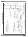
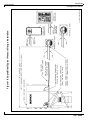
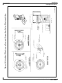
Supra-Blast
Cartridge Dust Collector
Installation and Operation Manual
TABLE OF CONTENTS
Page
1. IMPORTANT NOTICE ........................................................................................ 1
1.1 General Cautions ........................................................................................ 1
2. INTRODUCTION ...............................................................................................
2.1 Unit Nomenclature ......................................................................................
2.2 Description and Operation ..........................................................................
2.3 Air Filtering Operation .................................................................................
2.4 Filter Cleaning Cycle ...................................................................................
1
1
2
2
2
3. SPECIFICATION TABLE .................................................................................... 4
4. INSTALLATION .................................................................................................. 4
4.1 Off Loading and Inspection ......................................................................... 4
4.2 Installation Planning .................................................................................... 4
4.3 Assembly of Standard Equipment ............................................................... 8
4.4 Electrical Installation ................................................................................. 12
4.5 Compressed Air Connection ..................................................................... 21
4.6 Assembly of Optional Equipment .............................................................. 21
5. OPERATION ....................................................................................................
5.1 Start-Up.....................................................................................................
5.2 Checklist ....................................................................................................
5.3 Checking the Pulse Cleaning System with Your Controller .......................
5.4 Operating Adjustments..............................................................................
27
27
27
28
28
6. SERVICE .........................................................................................................
6.1 Cartridge Filter Removal and Replacement ..............................................
6.2 Cartridge Filter Seeding Procedures ........................................................
6.3 Dust Removal ............................................................................................
6.4 Servicing the Compressed Air Components .............................................
6.5 Servicing the Direct Drive Blower and Motor System ...............................
6.6 Servicing Optional Return Air Safety Filters (HEPA/ASHRAE) .................
6.7 Supra-Max Series Cartridge Filters ..........................................................
29
29
31
31
32
32
32
32
7. TROUBLESHOOTING GUIDE......................................................................... 33
8. ILLUSTRATED PARTS .................................................................................... 35
Supra-Blast Series Bill of Materials ................................................................. 36
i
Supra-Blast
Cartridge Dust Collector
Revised 02/02
1. IMPORTANT NOTICE
This manual contains important safety information and
precautionary measures. It is impossible to list all
potential hazards associated with every dust collection
system in each application. Proper use of the equipment
must be discussed with United Air Specialists, Inc.
(UAS) or your local DUST-HOG® representative.
Operating personnel must be aware of, and adhere to,
the most stringent safety procedures.
!
WA R N I N G
A warning symbol means people may be injured if the
procedures are not followed.
!
C AU T I O N
A caution symbol is used when equipment could be
damaged if the procedures are not followed.
2. INTRODUCTION
Thank you for selecting DUST-HOG dust collection
equipment to assist you in your commitment to a clean
and safe environment. We trust that in purchasing our
product you have recognized our commitment to
continually offer dust collection equipment engineered to
each dust collection need and manufactured to the highest
standards. If at any time you have a question about dust
collection, please do not hesitate to call your local
DUST-HOG representative or the nearest UAS customer
service office listed on the back cover of this manual.
The DUST-HOG Supra-Blast product line offers stateof-the-art cleaning power and dust collection capacity.
Designed to collect process-generated dusts,
Supra-Blast is the first centralized cartridge dust
collector with UAS’ exclusive air distribution insert within
the cartridge filter and QuickSeal filter access doors.
The Supra-Blast dust collector shall not be used for any
purpose not listed in this manual.
1.1 GENERAL CAUTIONS
1. Avoid mixing combustible materials such as
aluminum, paper, wood or other organic dusts with
dusts generated from grinding metals. A fire hazard
could develop from sparks entering the dust
collector. When collecting flammable or explosive
materials, the dust collector should be located
outdoors and incorporate the appropriate safety
measures and/or accessories.
2. When collecting emissions from spark-producing
processes, care must be taken to reduce any potential
fire hazards. System design should include methods
to prevent sparks from entering the dust collector.
Dust collectors do not contain fire extinguishing
equipment unless specifically ordered. Experts in the
field of fire extinguishing equipment should be
consulted for recommendations concerning proper fire
detection and suppression systems.
3. Some dust collection systems require explosion
venting. Consult your insurance underwriter, NFPA
(National Fire Protection Association) Manual and
your local fire authorities to determine the
requirements for explosion venting.
4. Be careful and conscientious — consult national and
local fire codes, waste disposal, safety and other
appropriate authorities. Comply with their
recommendations for the proper installation and
operation of dust collection equipment.
United Air Specialists, Inc.
As you review this manual, refer to Figure 1 for
assistance in identifying dust collector parts. The
Supra-Blast Specification Table in Section 3 provides
additional unit information.
2.1 UNIT NOMENCLATURE
The Supra-Blast product line is separated into two
models. SBS designates a single-filter configuration unit
and SBD designates a double-filter configuration unit.
EXAMPLE: SBS 4-2-H55
SBS – DUST-HOG Supra-Blast single-filter
configuration unit
4–
number of cartridge filters (2,4,6 or 8)
2–
number of filter tiers
H55 – unit base arrangement
H55 - hopper with 44" (112 cm) clearance for
standard 55 gallon (208 liter) drum
SD - hopper with 26" (66 cm) clearance for
UAS-supplied 30 gallon (114 liter) drum
OB - open bottom construction
BV - custom bin vent unit with open bottom
1
Revised 02/02
EXAMPLE: SBD 24-3-H55
SBD – DUST-HOG Supra-Blast double-filter
configuration unit
24 –
number of cartridge filters
3–
number of filter tiers
H55 – unit base arrangement
H55 - hopper with 44" (112 cm) clearance for
standard 55 gallon (208 liter) drum
SD - hopper with 26" (66 cm) clearance for
UAS-supplied 30 gallon (114 liter) drum
OB - open bottom construction
2.2 DESCRIPTION AND OPERATION
The DUST-HOG Supra-Blast is a high-efficiency,
cartridge dust collector designed to eliminate airborne
dust as it is generated. Contaminants are captured at
the source(s), then conveyed through ductwork to the
cartridge filter section (dirty air section) where the dust
is collected. Clean air is then discharged from the unit
through the clean air discharge.
2
Supra-Blast
Cartridge Dust Collector
2.3 AIR FILTERING OPERATION
The contaminated airstream is drawn into the dust
collector where its velocity is reduced by inlet baffle
plates to provide even air distribution across the entire
surface area of the cartridge filters. This design
enhances filtration efficiency by establishing a uniform
“dust cake” on the filters. The airstream is then directed
around the cartridge filters and down toward the hopper
where the heavier particles discharge to the dust
storage drum.
The contaminated air then passes through the cartridge
filters. The filter media strips the dust from the airstream
allowing only clean air to pass through the cartridge filter.
The air then passes into the clean air plenum, through a
blower package and is discharged from the unit.
2.4 FILTER CLEANING CYCLE
The dust collector is designed for on-line or downtime
cartridge filter cleaning by means of a customersupplied compressed air system.
During normal operation, the surface of the cartridge
filters become loaded with contaminants. The reverse
pulse cleaning mechanism provides brief bursts of
compressed air, directed through the diaphragm valves,
toward an air distribution tip and into the center of the
cartridge filter. This pulsing action dislodges the
collected particles from the media where they fall into
the hopper and are discharged to the dust storage
drum.
The Supra-Blast is a high-efficiency, horizontallyoriented cartridge dust collector equipped with 15"
(38 cm) outside diameter cartridge filters. The larger
diameter Supra-Max Series cartridge filter design allows
for lower pressure losses through the dust collector
while increasing the amount of media contained in each
filter. DUST-HOG Supra-Blast Series dust collectors
have pre-engineered backward-inclined or radial-type
optional blower packages in 3, 5, 71/2, 10, 15, 20, 25 and
30 HP (2.2, 3.7, 5.5, 7.5, 11, 15, 18.5 and 22 kW)
assemblies.
During the cleaning cycle, each row of cartridge filters is
cleaned individually. The solid-state sequential timer
actuates a solenoid valve, which allows an air
diaphragm valve to open for approximately 100
milliseconds. High-pressure air from the air manifold
reservoir is directed through the diaphragm valve toward
the air distribution tip mounted on the tubesheet in front
of the cartridge filter. The air is then directed into the
cartridge filter. The filter’s air distribution insert
maximizes the compressed air energy to increase the
amount of collected dust released from the filter surface.
There are two primary modes of operation — the air
filtering operation and filter cleaning cycle. Both modes
of operation are shown in Figure 1.
The dislodged dust removed from the filter is swept
downward into the hopper. The remaining filters are
cleaned sequentially. The sequencing is factory preset
at 10-second intervals and is adjustable to adapt to your
particular cleaning needs.
United Air Specialists, Inc.
Supra-Blast
Cartridge Dust Collector
Figure 1. Supra-Blast Air Filter Operation & Cleaning
44-10001-0001
Revised 02/02
United Air Specialists, Inc.
3
Supra-Blast
Cartridge Dust Collector
Revised 02/02
3. SPECIFICATION TABLE
Supra-Blast
Model
Filter
Quantity
Total
Supra-Netmax
Filter Media
Area
(FT2)
(M2)
620
58
1,240
115
1,860
173
2,480
230
Unit
Weight
Valve
Quantity
Module
Quantity
2
4
6
8
1
1
2
2
(LBS)
1,298
1,859
2,554
3,090
(KGS)
589
843
1,158
1,402
SBS
SBS
SBS
SBS
2
4
6
8
-
2
2
2
2
-
H55
H55
H55
H55
2
4
6
8
SBD
SBD
SBD
SBD
8
16
24
32
-
2
2
2
2
-
H55
H55
H55
H55
8
16
24
32
2,480
4,960
7,440
9,920
230
461
691
922
4
8
12
16
1
2
3
4
2,363
3,909
5,533
7,282
1,072
1,773
2,510
3,303
SBD
SBD
SBD
SBD
SBD
SBD
12
24
36
48
60
72
-
3
3
3
3
3
3
-
H55
H55
H55
H55
H55
H55
12
24
36
48
60
72
3,720
7,440
11,160
14,880
18,600
22,320
346
691
1,037
1,382
1,728
2,074
6
12
18
24
30
36
1
2
3
4
5
6
2,824
4,687
6,628
8,694
10,635
12,576
1,281
2,126
3,006
3,944
4,824
5,704
SBD
SBD
SBD
SBD
SBD
SBD
SBD
SBD
16
32
48
64
80
96
112
128
-
4
4
4
4
4
4
4
4
-
H55
H55
H55
H55
H55
H55
H55
H55
16
32
48
64
80
96
112
128
4,960
9,920
14,880
19,840
24,800
29,760
34,720
39,680
461
922
1,382
1,843
2,304
2,765
3,225
3,686
8
16
24
32
40
48
56
64
1
2
3
4
5
6
7
8
3,313
5,521
7,807
10,218
12,504
14,790
17,201
19,487
1,503
2,504
3,541
4,635
5,672
6,709
7,802
8,839
4. INSTALLATION
4.1 OFF LOADING AND INSPECTION
Supra-Blast dust collector modules are shipped
assembled on a skid(s). Other skids will contain the
hopper/leg assembly and other components. Other
accessories (afterfilter assemblies, blower packages,
dust storage drums, silencers, etc.) may be on
additional, separate skids.
!
C AU T I O N
Lift the dust collector components by the packing
skids or use the external lifting lugs provided on the
filter module. Do not lift the filter module of the dust
collector by placing lift truck forks through the
cartridge filter access doors. The filter support rails or
the conical air distribution tips installed on the
tubesheet could be damaged.
4
Upon receipt of your unit, check for any shipping damage.
A damaged carton indicates that the equipment may
have received rough handling during shipping that may
have caused internal damage. Notify your delivery
carrier and enter a claim if any damage is found.
4.2 INSTALLATION PLANNING
The proper location of your dust collection equipment is
very important. Refer to Figures 2 and 3 for typical
installation details.
Certain items should be considered when locating the
unit, such as emptying of the dust storage drum(s), filter
removal requirements, compressed air connections,
access to the clean air plenum, electrical connections,
blower location and discharge direction. The shortest
duct length with a minimum number of elbows will
maximize the performance of the unit. Ease of
maintenance should also be considered when selecting
the location and orientation of the system. Refer to
Figure 4 for recommended unit clearances.
United Air Specialists, Inc.
Supra-Blast
Cartridge Dust Collector
Figure 2. Supra-Blast SBS Typical Installation Diagram
44-10044-0001, REV A
Revised 02/02
United Air Specialists, Inc.
5
Supra-Blast
Cartridge Dust Collector
Figure 3. Supra-Blast SBD Typical Installation Diagram
44-10003-0001, REV A
Revised 02/02
6
United Air Specialists, Inc.
Supra-Blast
Cartridge Dust Collector
Figure 4. Recommended Unit Clearances
44-10007-0001
Revised 02/02
United Air Specialists, Inc.
7
Supra-Blast
Cartridge Dust Collector
Revised 02/02
In the case of spark producing processes, system
design should incorporate measures to prevent live
sparks from entering the dust collector. Consult local
authorities for the location of this unit and any additional
precautions to consider when collecting combustible,
explosive or hazardous dusts. General warnings and
cautions are provided in Section 1.1.
The Supra-Blast dust collector should be mounted on a
solid, level, reinforced concrete foundation. Other
mounting options are also possible. Structural
calculations for the foundation or other mounting
arrangements must include the weight of the collected
material and the weight of all auxiliary equipment
installed with the dust collector (ductwork, abrasive
inlet, blower package, afterfilter assembly, etc.). The
Supra-Blast Specification Table in Section 3 provides
unit weights. These weights must be considered
together with wind loading, seismic loading and other
live load ratings when designing the dust collector
foundation support structure. Consult a professional
engineer when designing the foundation for the unit.
Interconnecting ductwork should be designed to include
a volume control damper for regulating system design
airflow. United Air Specialists, Inc. offers optional volume
control dampers which can be installed on the air inlet/
outlet ductwork of the Supra-Blast unit to regulate
airflow. Ductwork must be properly sized to meet the
recommended air velocities for the material being
collected.
Follow ductwork design methods as listed in the
Industrial Ventilation Manual as recommended by the
American Conference of Governmental Industrial
Hygienists.
4.3 ASSEMBLY OF STANDARD EQUIPMENT
!
C AU T I O N
Use adequate safety measures when lifting and
assembling any heavy components. Consult your plant
safety personnel for recommendations.
Remove all crating, strapping and hold-down bolts.
Locate all hardware bags, sealant and other assembly
materials provided with your unit.
HOPPER ASSEMBLIES
The Supra-Blast series filter module is designed to
mount directly on top of the hopper assembly. A hopper
assembly consists of a hopper bin, legs, side diagonal
sway braces, rear diagonal sway braces, front horizontal
brace and hardware installation kit. Most Supra-Blast
hopper bins will be factory assembled with the legs and
sway bracing. Some hopper assemblies may be shipped
in pieces and will need to be assembled at the site.
If the hopper assembly is factory assembled, position
hopper and legs on the mounting pad. Shim legs as
required and secure leg assemblies to concrete
mounting pad with appropriate anchoring hardware.
Anchors should be provided by customer or contractor
according to local codes.
If the hopper sections are shipped in pieces for field
assembly, position legs as shown in “Plan Detail” on the
unit sales drawing. Bolt on sway braces using hardware
as shown in Figures 5 and 6. Leave all hardware handtight; shim legs as required.
Extend hopper leg alignment bolts through leg upper
surface (refer to Figure 7, View G). Fit hopper over leg
assemblies, positioning the corner holes of the hopper
over the alignment bolts in each leg gusset corner (refer
to Figure 7, View H).
Secure leg assemblies to concrete mounting pad with
appropriate anchoring hardware. Anchors should be
provided by customer or contractor according to local
codes.
FULLY-ASSEMBLED FILTER MODULE
SECTIONS
Apply two ribbons of sealant to hopper flange to create
“figure 8” pattern around mounting holes (refer to
Figure 7, View H).
!
C AU T I O N
In preparing to attach the filter module to the hopper,
connect lifting slings and spreader bars to all filter
module lifting lugs with clevis pins. Use spreader bars
to distribute the load evenly. Location must be clear of
all obstructions, such as utility lines or roof overhangs.
Place filter module onto hopper/leg assemblies,
positioning filter module corner holes over alignment
pins in leg gussets (refer to Figure 8, Detail K). Drift pins
will also be useful for locating the filter module section
onto the hopper.
8
United Air Specialists, Inc.
Figure 5. Leg Assembly Details
FIELD_INSTALL_DWG1/
SUPRABLAST/SALES/
FIELD_INSTALL_DRW/
SHEET 1
Revised 02/02
Supra-Blast
Cartridge Dust Collector
United Air Specialists, Inc.
9
Figure 6. Leg Brace Assembly Details
FIELD_INSTALL_DWG1/
SUPRABLAST/SALES/
FIELD_INSTALL_DRW/
SHEET 2
Revised 02/02
10
Supra-Blast
Cartridge Dust Collector
United Air Specialists, Inc.
Supra-Blast
Cartridge Dust Collector
Revised 02/02
NOTE: Each hopper assembly is equipped with four 1/2"
(13 mm) pry locations — two holes on front
flange and two holes on rear flange. Refer to
Figure 8, Detail K, to aid in aligning the hopper
flange with the module flange.
With filter module still supported, use hardware (refer to
Figure 8, Section P-P) to bolt the hopper and filter
module together. Securely tighten all hardware at the
filter module and hopper. Recheck leg assembly sway
braces to ensure they are tight. Install fasteners (bolt,
flat washer, lock-washer, nut) to all four pry locations.
Disconnect lifting slings and spreader bars used for
installation.
MULTIPLE, BOLT-TOGETHER MODULE
SECTIONS
For units that have multiple, bolt-together module
sections, remove the row of filters from the modules
nearest the bolting flange (refer to Section 6.1). Protect
the doors and filters removed by placing in a safe area
away from work area. Identify the different module
sections. There are left (bolt flange on the right side),
right (bolt flange on the left side) and possibly center
(bolt flanges on both sides) module sections.
Install all hopper/leg assemblies as previously described.
With multiple hoppers, the leg assemblies should be
bolted together (refer to Figure 5, Section F-F).
Apply two ribbons of sealant to only the first hopper
flange to create “figure 8” pattern around mounting
holes (refer to Figure 7, View H).
!
C AU T I O N
In preparing to attach the filter module to the hopper,
connect lifting slings and spreader bars to all filter
module lifting lugs with clevis pins. Distribute the load
evenly. Location must be clear of all obstructions, such
as utility lines or roof overhangs.
Place the appropriate filter module onto the hopper/leg
assembly to which the sealant has been applied,
positioning filter module corner holes over alignment
pins in leg gussets (refer to Figure 8, Detail K). Drift pins
will also be useful for locating the module section onto
the hopper.
NOTE: Each hopper assembly is equipped with four 1/2"
(13 mm) pry locations — two holes on front
flange and two holes on rear flange. Refer to
Figure 8, Detail K, to aid in aligning the hopper
flange with the module flange.
United Air Specialists, Inc.
With the filter module still supported, use hardware
(refer to Figure 8, Section P-P) to bolt the hopper and
filter module together. Securely tighten all hardware at
the filter module and hopper. Recheck leg assembly
sway braces to ensure they are tight. Install fasteners
(bolt, flat washer, lock-washer, nut) to all four pry
locations.
Disconnect lifting slings and spreader bars used for
installation.
Apply sealant to the next hopper to receive a filter
module (refer to Figure 7, View H). Apply sealant to the
side bolting flange of the next filter module to be
installed using the “figure 8” pattern (refer to Figure 9,
Detail J). Place this module on its hopper. Use the
hardware provided (refer to Figure 9, Detail L) and bolt
the module sections together. Bolt the filter module to
the hopper (refer to Figure 8, Section P-P). Securely
tighten all hardware at the filter module and hopper.
Recheck leg assembly sway braces to ensure they are
tight. Install fasteners (bolt, flat washer, lock-washer,
nut) to all four pry locations.
Disconnect the lifting slings and spreader bars used for
installation.
Repeat this process until all the module sections are in
place, securely fastened and anchored to the foundation.
Recheck all hardware connections to make certain they
are securely tightened. Remove lift slings and spreader
bars and clear all tools from the work area.
NOTE: Make certain all bolts (including the anchor
bolts) are properly tightened before proceeding
with the remainder of the installation.
Install all cartridge filters removed at the beginning of
the installation process and install the filter access
doors (refer to Section 6.1).
CLEAN AIR SECTION BOTTOM ACCESS
PANEL INSTALLATION
The bottom access panel and its gasket are shipped
loose with installation hardware. If the bottom access
will not be used for discharge ductwork, attach the panel
to the bottom opening using the hardware provided.
For top-mount blower packages of 20 HP (15 kW) or
larger, an additional set of support legs is provided.
The additional support legs must be mounted under the
filter module supporting the blower package (refer to
Figure 10). Bolt the mounting plate to the bottom of the
appropriate clean air plenum with the hardware
provided. Bolt the leg assemblies to the mounting plate
11
Supra-Blast
Cartridge Dust Collector
Revised 02/02
with the hardware provided. Secure leg assemblies to
the concrete mounting pad with appropriate anchoring
hardware.
4.4 ELECTRICAL INSTALLATION
!
C AU T I O N
All electrical work should be performed by a qualified
electrician in accordance with local electrical codes.
Disconnect electrical power before installing or
servicing any electrical component.
!
C AU T I O N
Avoid mounting the Supra-Clean, Supra-View or
Supra-I.Q. Panel on the collector due to vibration
generated from blower assembly and the pulsing
system.
4.4.2 PULSE CLEANING CONTROLS
For a more in-depth explanation of the cleaning control
features and options, refer to Section 5 or the Installation
and Operation Manual supplied with the Supra-Clean
timerboard, Supra-View Panel or Supra-I.Q. Diagnostics
Panel.
GENERAL
Several types of standard electrical components can
be installed to control and monitor your dust collector
ensuring proper cleaning of the cartridge filters. A fan
motor starter circuit is required to start and stop the
system. The motor starter circuit should consist of a
properly-sized, fused disconnect or circuit breaker,
contactor and overload relay for short circuit and overload
protection of the blower package. A 115/1/60 low voltage
(2 amp) control circuit is required for the pulse cleaning
controls. Any one of the following control configurations
can be used (refer to Figures 11-13 for wiring schematics):
•
Motor starter with Supra-Clean timerboard for
continuous pulse (Magnehelic® Guage). Refer to
Figure 11 for recommended wiring.
•
Motor starter with Supra-Clean timerboard for
setpoint pulse (Photohelic® Guages). Refer to Figure
11 for recommended wiring.
•
Motor starter with Supra-View Panel for self-contained
differential pressure display, pulse control and alarm.
Refer to Figure 12 for recommended wiring.
•
Motor starter with Supra-I.Q. Diagnostics Panel for
complete monitoring and automated pulse control.
Refer to Figure 13 for recommended wiring.
Refer to UAS sales order to verify the control
configuration purchased with your unit.
4.4.1
MOUNTING OF THE CONTROLS
Mount the motor starter for the fan motor control in a
convenient location. The motor starter is provided by the
customer, unless specifically ordered from UAS.
Mounting hardware for a UAS starter panel is provided
by the customer or contractor.
Mount the solid-state cleaning controls (Supra-Clean,
Supra-View or Supra-I.Q.) in a convenient location. It is
recommended that the controls be mounted on a wall or
pedestal in a convenient area subject to minimal
vibration and electrical noise.
12
4.4.3 SOLENOID VALVE ENCLOSURE WIRING
The solenoid valves at the dust collector must be wired
correctly to the pulse controls. Refer to Figure 14 when
making connections from the pulse controls (SupraClean timerboard, Supra-View Panel or Supra-I.Q.
Diagnostics Panel) to the solenoid valve enclosure(s).
Example: Figure 14 shows the SBD-XX-4 having eight
valve locations per module. This means when the
system pulses, “1” is the first pulse in the sequence, “2”
is the second, “3” is the third, etc.
When multiple dust collector modules are installed, daisy
chain the wiring so that each solenoid valve with the
same module location will pulse at the same time. This
means all #1 solenoid valves are tied together and wired
to pulse controller “OUT 1,” #2 solenoid valves are tied
together and wired to pulse controller “OUT 2,” etc. Refer
to Figure 14 for the Supra-Blast dust collector solenoid
valve wiring information. When cleaning, the pulse valves
sequence left to right, top to bottom.
Unless specified on the UAS sales order, the customer
will supply interconnecting material (conduit, wiring,
etc.) from the pulse controls to the dust collector.
4.4.4 HEATER WIRING
In cold or damp environments, the heater serves to
prevent the electric solenoid valves from freezing due to
cold temperatures or condensation. If optional solenoid
valve heater is purchased, each solenoid valve
enclosure will contain a 100-WATT cartridge heater
internally prewired to a thermostat.
The customer must supply a separate, 100-130VAC,
50-60Hz, 1 amp supply power to the heater circuit for
each module. The supply must be available to the module
solenoid valve enclosure(s) at all time (even when the
blower is shut down) to ensure temperature regulation
inside each solenoid valve enclosure is continual. When
United Air Specialists, Inc.
United Air Specialists, Inc.
Figure 7. Hopper Assembly Details
FIELD_INSTALL_DWG1/SUPRABLAST/SALES/FIELD_INSTALL_DRW/SHEET 3
Revised 02/02
Supra-Blast
Cartridge Dust Collector
13
14
FIELD_INSTALL_DWG1/SUPRABLAST/SALES/FIELD_INSTALL_DRW/SHEET 4
Figure 8. Module to Hopper Assembly Details
Revised 02/02
Supra-Blast
Cartridge Dust Collector
United Air Specialists, Inc.
United Air Specialists, Inc.
Figure 9. Multiple Filter Module Section Assembly Details
FIELD_INSTALL_DWG1/SUPRABLAST/SALES/FIELD_INSTALL_DRW/SHEET 5
Revised 02/02
Supra-Blast
Cartridge Dust Collector
15
Supra-Blast
Cartridge Dust Collector
Figure 10. Top-Mount Blower Support Leg Assembly
44-10064-0001
Revised 02/02
16
United Air Specialists, Inc.
Figure 11. Power and Elementary Wiring for Units with Supra-Clean Timerboard
and Magnehelic/Photohelic Control
44-10209-0001
04-2552, REV E
Revised 02/02
Supra-Blast
Cartridge Dust Collector
United Air Specialists, Inc.
17
Figure 12. Power and Elementary Wiring for Units with Supra-View Panel
44-10208-0002
04-2587
Revised 02/02
18
Supra-Blast
Cartridge Dust Collector
United Air Specialists, Inc.
United Air Specialists, Inc.
Figure 13. Power and Elementary Wiring for Units with Supra-I.Q. Diagnostics Panel
44-10210-0001
04-2553, REV D
Revised 02/02
Supra-Blast
Cartridge Dust Collector
19
Supra-Blast
Cartridge Dust Collector
Figure 14. Solenoid Wiring to Pulse Controls
61-10004-0001
04-2554, REV C
Revised 02/02
20
United Air Specialists, Inc.
Supra-Blast
Cartridge Dust Collector
Revised 02/02
multiple module solenoid valve enclosures with heaters
are installed, daisy chain the wiring so that each heater
will have 100/115/VAC, 50/60 Hz at all times. Make
certain enough current is available to supply all heaters.
Example: If three solenoid valve enclosures are
supplied with cartridge heaters, make certain the
voltage supply can deliver 3 amps (1 amp per heater).
4.5 COMPRESSED AIR CONNECTION
!
C AU T I O N
Do not allow water and/or oil from the compressed air
system into the compressed air manifold reservoir. To
ensure a clean, dry air supply, especially when the unit
is installed outdoors, a water filter with automatic drain
(or a condensate trap with automatic drain) and a
coalescing filter should be installed (refer to Figure 15).
Clean, dry, 90-110 PSIG (6.2-7.6 BAR) compressed air
is required for the pulse cleaning system to function
properly. Compressed air consumption is noted on the
UAS sales drawing. A shut-off valve, pressure regulator
and pressure gauge should be installed close to the
Supra-Blast unit. UAS recommends dedicated oil and
water removal filters be used to ensure clean, dry air is
delivered to the pulse system. Contact your local DUSTHOG representative for information about UAS’s
Pneumatic Valve Assembly. Refer to Figure 15 for
recommended compressed air piping and Table 1 below
for proper compressed air line sizing.
!
C AU T I O N
Using Table 1, select the proper diameter compressed
air line pipe to supply your dust collector. The final
connection size is a female 1" NPT fitting on each
module.
Pipe Diameter
Number of
Filter Section or
Modules
1-3
3-5
+5
1 inch (25 mm)
11/2 inch (38 mm)
2 inch (51 mm)
Distance of Supply Air
Piping Run From
Main Compressor Line
50 feet (15 meters)
100 feet (31 meters)
+100 feet (+31 meters)
4.6 ASSEMBLY OF OPTIONAL EQUIPMENT
BLOWER PACKAGE INSTALLATION
!
C AU T I O N
Anchor dust collector to concrete pad prior to installing
blower assembly. Make certain all hardware is
properly tightened.
If a top-mount blower package was ordered, read the
manufacturer’s Installation and Operation Manual
completely before installing the blower. The blower
Installation and Operation Manual is attached to the
fan package. Perform all pre-installation checks prior
to installing the blower.
!
C AU T I O N
If blower package has a 20 HP (15 kW) motor or
larger, ensure the blower support legs are installed
beneath the clean air plenum of the module to which
the blower will be mounted.
Remove the clean air plenum cover plate on top of the
filter module and save the mounting hardware. Ensure
ribbon gasket remains on the unit. Lift blower package
using safe, suitable means and position blower base
holes over filter module holes with blower discharge
pointing in the desired direction. Secure with bolt/
washer assemblies previously removed. Top-mount
blower packages include a blower outlet damper. Install
blower damper to outlet of blower assembly with
hardware provided.
If the blower package is a ground-mount blower, read
the manufacturer’s Installation and Operation Manual
completely before installing the blower. The blower
Installation and Operation Manual is attached to the fan
package. Perform all pre-installation checks prior to
installing the blower.
Outlet duckwork from the Supra-Blast unit to the blower
package can be connected to either the top or bottom
clean air section access panel(s). It is recommended
industry practice to provide vibration isolation between
the blower inlet and the dust collector outlet ducting.
Table 1 — Pipe Diameter Selection
DUCT SILENCER INSTALLATION
!
C AU T I O N
Purge the compressed air line to remove any debris
prior to making the final connection to the Supra-Blast
compressed air manifold(s). Apply pipe fitting sealant
on all compressed air supply piping fittings and
connections.
United Air Specialists, Inc.
A duct-type (in-line) silencer is designed to bolt directly
to the blower outlet damper flange. Make certain there
is adequate room for the silencer in the discharge
direction. Provide at least 24" (61 cm) of unobstructed
space at the end of the silencer discharge. The air
discharge should be directed into an open area, free of
obstructions and with consideration for personnel safety.
21
Supra-Blast
Cartridge Dust Collector
Figure 15. Pneumatic Valve Assembly
44-10042-0001
Revised 02/02
22
United Air Specialists, Inc.
Supra-Blast
Cartridge Dust Collector
Figure 16. Abrasive Inlet Installation
44-10045-0001
Revised 02/02
United Air Specialists, Inc.
23
Supra-Blast
Cartridge Dust Collector
Revised 02/02
!
C AU T I O N
The silencer will require a separate support. Do not
use the blower damper or outlet flange to support the
silencer. Apply silicone around the bolt holes of the
connecting flanges, lift the silencer into position and
secure with the hardware provided. Install permanent
supports (customer-supplied) and tighten all hardware
before removing the lifting device.
ROTARY AIR LOCK INSTALLATION
If a rotary air lock was ordered with the unit, the hopper
discharge will have an adapter already bolted to it. Make
certain the bolts connecting the adapter to the hopper
discharge are securely tightened.
Remove all packing from the rotary air lock and
determine its appropriate position. Keep in mind
required clearances, electrical connections and
maintenance. Apply sealant to the flange of the rotary
air lock and fasten to the adapter using M10 bolts,
washers and lock washers.
!
C AU T I O N
All electrical connections shall be made by a qualified
electrician according to all applicable codes. Refer to
the nameplate and/or documentation for voltage,
amperage, cycle and proper wiring. Refer to rotary air
lock vendor documentation attached with air lock
device.
!
Remove the front access panel(s) located above the
QuickSeal filter access doors. Save the hardware. The
hardware will be used to attach the abrasive inlet.
Remove any remaining gasket material from around
the perimeter of the opening.
Apply a 1/4" (6 mm) bead of sealant around the
perimeter of the access opening in a “figure 8” pattern
around the bolt holes. Align the hole pattern on the
abrasive inlet with the hole pattern on the unit and bolt
together using the hardware removed earlier. Fasten the
inlet ductwork securely to the abrasive inlet assembly.
The bottom plate of the abrasive inlet will serve as an
inspection plate. If access to the abrasive inlet is
required, remove and clean out the bottom plate of the
inlet prior to servicing. Do not damage the ribbon of
gasket and reuse after cleaning the gasket surfaces.
DRUM LID INSTALLATION
The drum lid package is an optional accessory for
Supra-Blast series dust collectors.
Remove the drum lid package from its shipping carton.
Place the drum lid on the 55-gallon (208 liter) drum (H55)
or 30-gallon (114 liter) short drum (SD). Slide the 14"
(360 mm) diameter hose over the drum lid and secure
with a hose clamp. Position the drum assembly under the
unit, slide the hose up onto the discharge adapter collar
on the hopper and secure with a hose clamp.
C AU T I O N
Disconnect all power to the rotary air lock before
servicing. There are moving parts on the rotary air
lock. Do not allow any object to be placed in or near
the rotary air lock during operation.
!
C AU T I O N
Verify rotary air lock rotation matches rotation arrows
affixed to assembly.
ABRASIVE INLET INSTALLATION
The abrasive inlet is designed to use the front access
panel(s) of the Supra-Blast series modules as the inlet
area to the unit. There are two styles available - a single
or dual module abrasive inlet. Each is designed to fit
over the appropriate number of front access panels to
serve as a single inlet point for one or two modules
(refer to Figure 16).
44-10046-0001
Figure 17. Drum Lid Installation
24
United Air Specialists, Inc.
Supra-Blast
Cartridge Dust Collector
Revised 02/02
If a drum lid latch kit was ordered, attach the separate
clamp band around the 55-gallon (208 liter) drum or
30-gallon (114 liter) short drum, leaving the cinch bolt
loose. Position the three latch pawls onto the drum lid
catches, rotating the drum lid as required. Tighten the
cinch bolt and adjust the latch tension or band
placement as required (refer to Figure 17).
The Photohelic Guage and mounting bracket should be
installed within sight of the Supra-Blast as shown in
Figure 18. Hardware to mount the bracket to the support
structure is not supplied by UAS.
If a slide gate was ordered, it was factory installed on
the hopper. Open the slide gate. Repeat for multiple
drum lid connections.
NOTE: Make certain to install the two jumper wires
(customer-supplied) as shown in the instruction
manual provided with the gauge.
NOTE: The hopper(s) is not designed for dust storage.
The slide gate should remain open during
normal operation.
Refer to the manufacturer’s instructions for outdoor
installation.
INLET COLLAR AND BLANK COVER PLATE
INSTALLATION
Inlet collar and blank cover plates bolt directly to the
Supra-Blast unit. Inlet and outlet collar assemblies are
specified with initial order. If inlet diameters or locations
are not specified with initial order, the dust collector is
supplied with all blank cover plates.
MAGNEHELIC® GUAGE INSTALLATION
If your system was ordered with a Magnehelic Guage,
remove it and the hardware from the box. Instructions
for mounting and connecting the Magnehelic Guage are
provided by the manufacturer. Follow these instructions
using the hardware provided. The gauge should be
installed within sight of the Supra-Blast unit as shown in
Figure 18.
NOTE: The hardware provided is designed for surface
mounting of the Magnehelic Guage. Make
certain to install the 1/8" NPT pipe plugs in the
pressure ports on the back of the gauge.
!
WA R N I N G
Failure to install 1/8" NPT pipe plugs in pressure ports
on the rear of the Magnehelic Guage will cause the
gauge to read incorrectly.
Install the tube fittings in the pressure ports on the side
of the gauge. Mount it to the bracket, and the bracket to
a support structure.
The Photohelic Guage requires electrical connections.
Refer to Figure 11 for details.
FINAL CONNECTIONS FOR ALL
GAUGE OPTIONS
For any control system, connect the black, plastic
pressure tubing (25 feet [7.5 meters] provide by UAS)
to the gauge or panel fittings and the Supra-Blast unit.
Connect the dirty air plenum of the Supra-Blast to the
high pressure port on the gauge or panel as shown in
Figure 18. Connect the clean air plenum of the SupraBlast to the low pressure port on the gauge or panel as
shown in Figure 18. Zero, calibrate and maintain the
gauge as recommended by the manufacturer.
NOTE: Gauge should be installed within 50 feet
(15 meters) of the dust collector.
SUPRA-CLEAN TIMERBOARD INSTALLATION
Please refer to the Supra-Clean Installation and
Operation Manual for proper installation details.
SUPRA-VIEW PANEL INSTALLATION
Please refer to the Supra-View Installation and
Operation Manual for proper installation details.
SUPRA-I.Q. DIAGNOSTICS PANEL
INSTALLATION
If your system was ordered with a Supra-I.Q. Diagnostics
Panel, please refer to the Supra-I.Q. Installation and
Operation Manual for proper installation details.
REMOTE BLOWER START/STOP ASSEMBLY
PHOTOHELIC® GUAGE INSTALLATION
If your system was ordered with a Photohelic Guage,
remove it and the hardware from the box. Instructions
for mounting and connecting the Photohelic Guage are
provided by the manufacturer. Follow these instructions
using the hardware and UAS mounting bracket provided.
United Air Specialists, Inc.
A remote blower start/stop pushbutton station is available
for field installation on Supra-Blast assemblies that have
been configured with a combination magnetic motor/
blower starter control package supplied by UAS. The
combination magnetic motor/blower starter control
package must be configured and wired in accordance
with Figure 11, 12 or 13. The customer is required to
25
Supra-Blast
Cartridge Dust Collector
Figure 18. Supra-Blast Typical Pressure Gauge Installation
44-10043-0001, REV A
Revised 02/02
26
United Air Specialists, Inc.
Supra-Blast
Cartridge Dust Collector
Revised 02/02
supply interconnecting signal cord and mounting
hardware for remote blower start/stop assembly
installation. Remove jumper between terminals L and 20
in the combination magnetic motor/blower starter control
package as shown in Figure 11, 12 or 13.
5. OPERATION
!
C AU T I O N
Shut off unit disconnect and lock out all electrical power
to the dust collector prior to performing service work.
!
C AU T I O N
Prior to unit start-up, all installation set-up instructions
must be completed as specified by this manual, the
Supra-Clean Installation and Operation Manual,
Supra-View Installation and Operation Manual, SupraI.Q. Installation and Operation Manual, as well as any
manuals supplied by other equipment manufacturers,
as they apply to your dust collector.
5.1
START-UP
Inspect the installation area and make certain no tools,
parts, etc., have been left anywhere on or inside the
Supra-Blast unit. Check blower discharge to make
certain it is free from all debris.
Start motor/blower and check for proper rotation. A
rotation arrow is located on the blower housing. All topmount blower assemblies rotate in a clockwise rotation as
viewed from the driven end (motor end with motor cooling
fan). If the blower is rotating in the opposite direction,
disconnect the power to the motor starter. For 3-phase
blowers, interchange any two power wires to the motor at
the load side of the motor starter contactor. For singlephase power, refer to motor nameplate for which two
wires to interchange at motor junction box. Engage
starter disconnect, start blower and recheck rotation.
NOTE: Proper blower rotation is required to move the
designed amount of air. A blower rotating in the
incorrect direction will only move about 40% of
design airflow.
!
C AU T I O N
The blower assembly provided by United Air
Specialists, Inc. includes an outlet damper. If the
blower assembly was purchased separately, ensure a
volume control damper is included somewhere in the
dust collection system. Close the blower discharge
damper to the 50% open position and tighten in place.
If a volume control damper is provided in another part
of the dust collection system, adjust second damper
to the 50% open position and tighten in place.
United Air Specialists, Inc.
NOTE: It is important that the air volume of the dust
collection system is at design conditions at
system start-up. There is a minimal pressure
differential across new cartridge filters. If the
volume control damper is not correctly
adjusted, the air volume will be above design
conditions for airflow and may affect the
cartridge filter life.
!
C AU T I O N
Verify dust collector system airflow is adjusted to design
conditions with a new, clean filter using the volume control
dampers installed in the system. Failure to properly
adjust system airflow may affect cartridge filter life.
The air volume should be adjusted based on the
performance of the entire system. Air volume control
damper adjusted to the system design conditions.
Closing the volume control damper decreases system
airflow. Opening the volume control damper increases
system airflow.
On certain applications, it may be beneficial to “seed” or
pre-coat the original or replacement cartridge filters. This
process introduces a certain amount of coating
particulate (usually crushed limestone, agricultural lime or
other specifically marketed pre-coat) in light
concentration to deposit a thin coating of material which
acts as an aid to filtration. This deposited dust cake keeps
the dust loading on the surface of the cartridge filter. This
process will increase filter life and efficiency while
allowing the cleaning system to operate more effectively.
For filter seeding procedures, refer to Section 6.2.
Turn on the compressed air supply to the dust collector
air manifold reservoir. Adjust the pressure regulator until
the gauge reads 90-110 PSIG (6.2-7.6 BAR).
5.2 CHECKLIST
Check the discharge of the blower assembly. Initially,
some dust may discharge from the blower assembly as
the filters are seasoned. This may last several minutes
after which the discharge air should remain visibly clean.
Measure the total airflow and static pressure at the inlet
to the Supra-Blast unit. Adjust the blower outlet damper
for the desired airflow. Check to ensure that adequate
air is being drawn into each of the collection points of
the system. Adjust the individual dampers for each
operation to balance the system airflow. Recheck the
total system airflow and adjust the blower damper to
desired system airflow. This procedure may need to be
repeated several times until the entire system is within
system design airflow specifications.
27
Supra-Blast
Cartridge Dust Collector
Revised 02/02
Check the differential pressure reading across the
dust collector clean to dirty air sections. A normal
differential pressure drop reading is between 1"-6" w.g.
(25-152 mmAq). At start-up, this reading is generally in
the 1"-3" w.g. (25-76 mmAq) range. Please list the
reading here for future reference.
Initial dust collector differential pressure reading across
filters is ___________ " w.g. or ___________(mmAq) on
___________ (date).
NOTE: If your system is controlled by the Supra-I.Q.
Diagnostics Panel, the yellow airflow alert light
may be illuminated. This is normal unitl the “Air
Flow Calibration” routine has been performed
at the Supra-I.Q. Diagnostics Panel. This must
be performed during start-up of your dust
collection system once all of the inlet(s) and
ductwork is in place and the outlet damper (if
required) is opened 75%. Refer to the SupraI.Q. Installation and Operation Manual and
perform the “Code 4 - Airflow Settings” steps.
5.3 CHECKING THE PULSE CLEANING
SYSTEM WITH YOUR CONTROLLER
Check the cleaning system for proper operation. The
compressed air pressure should be between 90-110
PSIG (6.2-7.6 BAR). The Supra-Clean, Supra-View and
Supra-I.Q. panels are factory set to pulse every 10
seconds. Refer to the Supra-Clean, Supra-View or
Supra-I.Q. Installation and Operation Manual to change
these initial settings. Check to ensure the pulse
(diaphragm) valves are “firing” at approximately 10second intervals and deliver a crisp sounding pulse to
each filter. The valves should not deliver a weak or
lingering pulse. To check the pulse sequence for proper
firing, perform the following:
•
If your system is supplied with a Supra-Clean
timerboard (with Magnehelic or Photohelic Guage) or
Supra-View Panel, place the “Continuous Clean/PS”
switch on the timerboard to the “Continuous Clean”
position. The MOT AUX terminals at the timerboard
must have continuity for the pulsing to become
active. To activate, energize the motor starter to
close the isolated auxiliary contact wired to the
timerboard MOT AUX terminals. Verify robust and
consistent pulse firing of each valve.
•
If your system is supplied with a Supra-I.Q.
Diagnostics Panel, place the system in “Continuous
Clean” by entering Code 5. At the “SET MODE” state,
enter “1” for continuous cleaning. Terminals 1 and 2 at
28
terminal strip P7 must have continuity for the cleaning
system to activate. Allow 45 seconds after panel
power-up for pulsing to start as the Supra-I.Q.
cleaning mode(s) operate on a delay. Verify robust
and consistent pulse firing of each valve. When test is
complete, enter code 5. At the “SET MODE” state,
enter “2” for Auto-tune cleaning mode.
5.4 OPERATING ADJUSTMENTS
Please confirm the type of pulse cleaning controller
delivered with your system. Your system was delivered
with one of the following:
•
Magnehelic Guage with Supra-Clean timerboard
•
Photohelic Guage with Supra-Clean timerboard
•
Supra-View Pulse Panel
•
Supra-I.Q. Diagnostics Panel
NOTE: It is important that the compressed air pressure
in the manifold is above 90 PSIG immediately
prior to a pulse. If the delivery capability of your
compressed air source cannot return the
manifold pressure to above 90 PSIG during the
“Pulse Delay” (time between pulses) interval,
adjust the pulse delay at the timerboard or
Supra-I.Q. and monitor the pressure. A longer
interval will raise the operating pressure and a
shorter interval will lower the operating
pressure. Allow sufficient time for the system to
stabilize after each adjustment before making
any further adjustment. Adjust until the desired
manifold pressure is reached.
MAGNEHELIC GUAGE CONTROL WITH
SUPRA-CLEAN TIMERBOARD
When using a Magnehelic Guage with Supra-Clean
timerboard, the timerboard is always set to “Continuous
Clean” pulse mode. If the filters are operating at a higher
or lower pressure than desired, adjusting the pulse
frequency (Pulse Delay) can often modify the steadystate pressure. The factory setting is 10-second
intervals. Adjust the “Pulse Delay” on the Supra-Clean
timerboard and monitor the pressure on the Magnehelic
Guage. A longer interval will raise the operating
pressure and a short interval will lower the operating
pressure. Allow sufficient time for the system to stabilize
after each adjustment before making any further
adjustment. Adjust until the desired manifold pressure is
reached.
United Air Specialists, Inc.
Supra-Blast
Cartridge Dust Collector
Revised 02/02
PHOTOHELIC GUAGE CONTROL WITH
SUPRA-CLEAN TIMERBOARD
When using a Photohelic Guage with Supra-Clean
timerboard, the timerboard is set to “PS” pulse mode
(pulse cleaning activated by the Photohelic control) or
“Continuous Clean” pulse mode to override the
Photohelic Guage. With the Photohelic Guage control,
the desired pressure can be maintained by adjusting the
high and low setpoints on the gauge. Adjust the upper
setpoint to the desired pressure settings plus 0.25"
(factory recommended setting is 3"). Adjust the lower
setpoint to the desired setting minus 0.25" (factory
recommended setting is 2.5"). This allows a 0.5"
“deadband” and the pulse system will maintain the
desired pressure (factory recommended operating point
is 2.75"). If the pressure remains above the desired
operating point, the pulse frequency can be increased
(shorter “Pulse Delay”). The high and low needle
setpoints on the Photohelic Guage can be adjusted as
the filters season and continuous pulsing occurs. Adjust
both needles upward in 0.5" increments until pulsing
stops. Continue adjustments, when required, until the
high setpoint reaches 6". No further adjustments should
be made above 6" w.g.
SUPRA-VIEW PULSE PANEL
When using the Supra-View panel, the pulsing controls
can be set to “PS” pulse mode (“On-Demand” cleaning
similar to Photohelic control) or “Continuous Clean”
pulse cleaning. The Supra-View includes a cartridge
differential measurement/display, pulse time sequence
controls and a “customer usable” high cartridge
pressure alarm contact in one enclosed assembly. The
high, low and alarm setpoints are adjusted by opening
the enclosure door and adjusting the appropriate
selector switches for desired control. Adjustments to the
setpoints can only be done with the door open. Refer to
the Supra-View Installation and Operation Manual for
adjustment details or refer to the inside of the SupraView enclosure door for operating instructions.
SUPRA-I.Q. DIAGNOSTIC PANEL
The Supra-I.Q. Diagnostics Panel can be set to operate
in Continuous Clean, Setpoint Clean (similar to
Photohelic control) or “Auto-tune” Clean mode. Autotune mode is designed to conserve compressed air
usage while maintaining the lowest possible cartridge
differential pressure. It allows the minimal amount of
compressed air usage while maximizing filter life. In
Auto-tune mode, the controller will automatically adjust
United Air Specialists, Inc.
the filter pressure to obtain the most cost-effective
setting. Please refer to the Supra-I.Q. Installation and
Operation Manual for a complete listing of operating
parameters and adjustment instructions.
ALL CONTROL OPTIONS
As the cartridge filters become loaded with dust, the
differential pressure across the filters will increase. This
will result in a loss of air volume. Should the dust
collection capture effectiveness be reduced, open the
flow control damper to return the system to the original
design air volume.
6. SERVICE
Before servicing dust collector, note the
following:
1. Disconnect electrical power to the unit and control panel.
2. Close off and slowly bleed the compressed air supply
from the air manifold reservoir. Air manifold reservoir
pressure should be reduced to 0 PSIG (0 BAR).
3. Collected dust may be hazardous. Consult proper
authorities for handling and disposal.
4. Collected dust may be a potential fire hazard.
Welding, grinding or operations involving open
flames should not be performed without fire
protection measures in place. Refer to Section 1
of this manual for additional precautions.
5. Wear appropriate protective clothing when servicing
dust collector.
6. Disposal of collected dust must be according to
federal, state and local regulations and all
appropriate authorities.
6.1 CARTRIDGE FILTER REMOVAL AND
REPLACEMENT
Supra-Max series cartridge filters are the only
replacement filters which provide the superior level
of performance expected from the Supra-Blast dust
collector.
Replacement cartridge filters should be ordered when
the differential pressure is consistently above 6" w.g.
(152 mmAq) or system airflow is inadequate. To order
filters, call the nearest United Air Specialists office listed
on the back cover of this manual.
29
Figure 19. QuickSeal Filter Access Door and Supra-Max Series Filter Installation
44-10006-0001
Revised 02/02
30
Supra-Blast
Cartridge Dust Collector
United Air Specialists, Inc.
Supra-Blast
Cartridge Dust Collector
Revised 02/02
TO REPLACE CARTRIDGE FILTERS
(refer to Figure 19):
1. Read and follow caution instructions in Section 6
before servicing dust collector. Start with the top row
of QuickSeal doors.
2. Tap the metal surface of each door cover to remove
collected particles from the inner door gasket. Pull
the QuickSeal door handle away from the dust
collector until the handle makes a 90° angle with the
door cover. The door assembly is now in an
unlatched position. Lift the QuickSeal filter door
assembly upward until the door rods clear the side
support brackets. Pull the filter door assembly away
from the dust collector. Tilt the filter door cover away
from the dust collector once free from the support
brackets to trap any dust on the inside of
the access cover. Dispose of dust into a suitable
container. Place filter door assembly in a safe place.
3. Move filter from side to side to break the gasket
seal between filter-to-filter and filter-to-tubesheet
locations. Rotate filter 180° to allow the dust on top
of the cartridge filter to fall into the dust collector
hopper.
4. Slide the filter out of the dust collector and transfer
to a suitable disposal container. For double filter
configuration units, grab and pull forward the filter
extraction tool by the rod handle located between the
filter support tracks. The extraction tool is designed
to move the rear filter 18" (45 cm) away from the
tubesheet to ease removal of the filter. Place the
second cartridge filter into a suitable disposal
container. Repeat this procedure for the remaining
filters.
5. Inspect the tubesheet and make certain the gasket
sealing area is free of dust to ensure proper sealing
of the new filter. Make certain area is dry after
cleaning process is complete.
6. Install a new Supra-Max series cartridge filter(s) into
each filter hole, gasket end first. Clean the filter
access door gaskets and align filter door assembly
with door rod support brackets on the dust collector.
Door handle must be placed at a 90° angle to filter
access door prior to placing the filter door assembly
support rod in the support brackets (refer to Figure
19). The flat surface of the door handle should be
facing downward. To close the filter access door,
push the door handle upward, toward the unit.
United Air Specialists, Inc.
!
WA R N I N G
The QuickSeal filter access door handle must be in a
perpendicular orientation to door surface prior to being
closed. A flat solid section of door handle will be
visible when door assembly is in the properly closed
position (refer to Figure 19).
!
WA R N I N G
If cam surface of the door handle is visible, QuickSeal
filter door assembly has been improperly installed.
7. The Supra-Blast dust collector is now ready to be
placed back in service. Reconnect electrical power
and air supply. Please follow the initial start-up
checklist to ensure proper unit performance.
6.2 CARTRIDGE FILTER SEEDING
PROCEDURES
Before seeding the cartridge filters, remove any
afterfilter(s) since a small amount of particulate will
initially pass through the cartridge filters. To begin
seeding filters, turn cartridge filter cleaning system off,
then turn fan system on. Introduce the seeding material
by slowly and gently shaking the material next to an
extraction hood or into the drum lid opening (remove
drum) where it can be drawn into the dust collector. The
seed material should be drawn in as a continuous
“cloud,” trying to avoid excessively heavy dust clouds.
Continue to feed the seeding material until the reading
on the dust collector differential gauge increases by 1"
w.g. (25 mmAq) or one to two pounds of seed material
per filter have been added. Replace or re-install the
afterfilter and the dust storage drum before operating
the dust collector.
6.3 DUST REMOVAL
!
C AU T I O N
Do not let the dust storage drum overfill. This can
cause poor dust collector performance and require
extensive clean-up due to the overflow of dust when
removing the collection container(s).
Turn off the dust collector (power to fan system and
compressed air to cleaning system) and empty the dust
storage drum as necessary to prevent dust from
accumulating in the hopper(s). Empty the dust storage
drum(s) when two-thirds full. If the hopper has a slide
31
Supra-Blast
Cartridge Dust Collector
Revised 02/02
gate, close the slide gate before servicing the dust
storage drum(s). The dust collector fan and compressed
air cleaning systems do not have to be turned off if the
hopper slide gate is closed prior to servicing storage
drums. Remember to open the slide gate when the dust
storage drum is replaced.
6.4 SERVICING THE COMPRESSED AIR
COMPONENTS
!
C AU T I O N
Shut off and slowly release the pressure in the
compressed air piping or the Supra-Blast compressed
air manifold reservoir prior to servicing this equipment.
1. The compressed air system should be periodically
checked to ensure clean, dry, oil-free air is
delivered to the Supra-Blast dust collector. Check
the compressed air components and service as
recommended by the manufacturer.
2. Periodically check the dust collector air manifold
reservoir(s) for contaminants and drain any
condensed liquid from manifold reservoirs. It is
recommended that the customer install an automatic
air line drain valve at the lowest section of the
compressed air line piping to the dust collector
(refer to Figure 15).
3. With the compressed air supply turned on, check the
diaphragm valves, electronic solenoid valves and
interconnecting tubing between both devices for any
air leakage. Replace any components that are
defective or worn.
6.5 SERVICING THE DIRECT DRIVE
BLOWER AND MOTOR SYSTEM
!
C AU T I O N
All electrical work should be performed by a qualified
electrician in accordance with local electrical codes.
Disconnect electrical power before installing or
servicing any electrical component.
Periodically inspect fan blades to ensure proper fan life.
Clean the fan blades of any deposited material. Grease
motor(s) every 3,600 hours with high grade ball and
bearing grease. Recommended greases are Shell
Dolium or Chevron SRI-2.
Refer to blower assembly Installation and Operation
Manual provided with blower assembly for additional
servicing requirements.
6.6 SERVICING OPTIONAL RETURN AIR
SAFETY FILTERS (HEPA/ASHRAE)
Periodically check the pressure drop across the return
air safety filters. Replace when the differential pressure
drop exceeds 2" w.g. (51 mmAq) for ASHRAE filters and
3" w.g. (76 mmAq) for HEPA filters.
6.7 SUPRA-MAX SERIES CARTRIDGE FILTERS
The Supra-Blast product line is designed to accept
Supra-Max Series cartridge filters. Table 2 highlights the
most common Supra-Max cartridge filters.
United Air Specialists will custom design Supra-Max
cartridge filters for application-specific systems. Contact
the nearest United Air Specialists office listed on the back
cover of this manual for additional information.
Magnehelic® and Photohelic® are registered trademarks of Dwyer
Instruments, Inc.
Supra-Max Series
UAS Part Number
General Description of Filter Media
Supra-Netmax
33-10001-0001
80/20 mixture of cellulose/polyester
Supra-Netmax-FR
33-10001-0002
80/20 mixture of cellulose/polyester with fire retardant
material treatment
Supra-Fibrousmax
33-10001-0003
Half the media quantity of the Supra-Netmax
Supra-Fibrousmax-FR
33-10001-0004
Half the media quantity of the Supra-Netmax-FR
Supra-Fibrousmax-W
33-10001-0005
Mixture of polyester and fiberglass fibers
Supra-Releasemax-P
33-10001-0007
Spun–bond polyester fibers
Supra-Releasemax-T
33-10001-0008
Spun–bond polyester fibers with PTFE surface membrane
Table 2 — Supra-Max Series Cartridge Filters
32
United Air Specialists, Inc.
Supra-Blast
Cartridge Dust Collector
Revised 02/02
7. TROUBLESHOOTING GUIDE
Use the troubleshooting guide to correct any problems
that occur with your dust collection unit. If the problem or
condition continues, contact the nearest UAS customer
service office listed on the back cover of this manual.
!
PROBLEM
Motor/blower won’t start or
won’t stay running.
Dust emissions from clean
air discharge.
WA R N I N G
All electrical/mechanical troubleshooting should be
performed by a qualified electrical/maintenance
individual familiar with UAS equipment.
C AU T I O N
All electrical wiring troubleshooting should be
performed by a qualified electrician in accordance
with local electrical codes.
Insufficient airflow.
!
!
C AU T I O N
Prior to troubleshooting any equipment, read the
Installation and Operation Manuals for each piece of
equipment to be serviced.
POSSIBLE CAUSES
RECOMMENDED SOLUTIONS
Blower rotation is running in reverse.
Reverse blower rotation (refer to Section 5.1).
Supply power not operational.
Check input power to motor circuits for proper
voltage on all legs.
Improper electrical wiring.
Check and correct internal motor wiring for proper
connections based on the incoming line voltage.
Check control voltage power supply (i.e., fuses,
transformer, etc.).
Starter overloads tripped.
Check for proper motor starter overload rating
against full load amps on motor nameplate. Adjust
or replace overloads as required.
Hopper discharge open to
atmosphere.
Ensure drum is properly sealed against drum lid
package. Ensure drum lid package is properly
installed (refer to Figure 17).
Blower damper not properly adjusted.
Check motor current draw and close volumetric
control damper or silencer damper until amperage
draw is below full load rating of motor.
Filters not installed properly.
Inspect and reinstall cartridge filters (refer to
Section 6).
Filters are damaged.
Replace damaged filter(s) with new Supra-Max
series cartridge filter(s).
Filter access doors not installed
properly.
Remove and reinstall QuickSeal filter access door
assembly (refer to Figure 19 and Section 6).
New filters are not seasoned or
pre-seeded.
Allow filters to seed during normal operation or
pre-seed cartridge filters (refer to Section 6.2).
Blower rotation is running in reverse.
Reverse blower rotation (refer to Section 5.1).
Loose or open access.
Remove QuickSeal filter access door assembly,
verify filters are properly installed and reinstall door
assembly (refer to Section 6.1 and Figure 19). Verify
drum lid is installed properly (refer to Figure 17).
Volumetric duct dampers or blower
outlet damper is not positioned
properly.
Adjust dampers to allow for sufficient air volume
(refer to Sections 5.1 and 5.2).
Air inlet(s) obstructed.
Inspect and clean all hoods and other machine
connections.
Filters plugged.
Refer to troubleshooting procedures for continual
pressure drop.
United Air Specialists, Inc.
33
Supra-Blast
Cartridge Dust Collector
Revised 02/02
7. TROUBLESHOOTING GUIDE (CONTINUED)
PROBLEM
Continual, excessive pressure
drop (over 7" [178 mm]) on filter
monitoring gauge.
POSSIBLE CAUSES
RECOMMENDED SOLUTIONS
Compressed air supply problems.
Check incoming compressed air for proper supply at
air manifold reservoir (90-110 PSIG [6.4-7.2 BAR]),
pulse flow (2.2 cubic feet [62 liters] per pulse) and pulse
duration (100 milliseconds). Correct any problems.
Pulse cleaning system not
functioning properly.
Check incoming 110-115 VAC power to Supra-Clean
timerboard, Supra-View Panel or Supra-I.Q.
Diagnostics Panel. Check control panel boards for
blown fuses. Check 110-115 VAC supply power
circuit (transformer, primary/secondary fuses, etc.).
Replace as necessary. Consult the Supra-Clean,
Supra-View or Supra-I.Q. Installation and Operation
Manual for additional troubleshooting ideas.
Check for 110-115 VAC output from timerboards to
solenoid valves. If incoming voltage (110-115 VAC)
supply to timerboards is correct and there are no
blown fuses, replace timerboards (Supra-Clean,
Supra-View or Supra-I.Q.). Consult the Supra-Clean,
Supra-View or Supra-I.Q. Installation and Operation
Manual for additional troubleshooting ideas.
34
Photohelic Guage not properly
adjusted.
Reduce high setpoint on Photohelic Guage to
3" (76 mm). Reduce low setpoint on Photohelic
Guage to 2.5" (64 mm) (refer to Section 5.4).
Pulse system not properly adjusted.
Check for proper pulse valve operation (refer to
Section 5.2). Correct pulse interval settings. Replace
damaged parts as necessary.
Pulse settings incorrect.
Adjust pulse on-time interval to 0.10 seconds.
Adjust pulse off-time interval to 10 seconds.
Consult Supra-Clean, Supra-View or Supra-I.Q.
Installation and Operation Manual for additional
troubleshooting procedures.
Dust storage drum is full.
Empty drum and clean out hopper (refer to
Section 6.3).
Filters are at the end of their
useful life.
Replace cartridge filters with Supra-Max series
cartridge filters from UAS. Each cartridge filter has
a filter part number label affixed to end cap
(refer to Table 2 for the most common Supra-Max
series cartridge filters).
Air inlet and/or outlet ductwork
are undersized.
Increase air inlet and/or ductwork sizes to reduce
duct line static pressure losses. Follow ductwork
design methods as listed in Industrial Ventilation
Manual by American Conference of Governmental
Industrial Hygienists.
United Air Specialists, Inc.
Supra-Blast
Cartridge Dust Collector
Revised 02/02
8. ILLUSTRATED PARTS
44-10009-0001
®
DUST-HOG Supra-Blast Series
United Air Specialists, Inc.
35
Supra-Blast
Cartridge Dust Collector
Revised 02/02
Supra-Blast Series Dust Collector Bill of Materials
Item
1
2
2a
2b
2c
2d
2e
2f
2g
3
3a
4
5
5a
6
7
7a
8
8a
9
9a
9a
9b
9c
9d
9e
10
11
12
13
14
15
16
17
18
18a
18b
18c
18d
19
36
Part No.
Description
33-10001-XXXX
02-10019-0001
42-10002-0001
42-10005-0001
Supra-Max Series Cartridge Filter (refer to Section 6.7 for filter selections)
QuickSeal Filter Access Door Assembly
External Filter Door Seal Gasket
Internal Filter Door Seal Gasket
Door Panel
10-10143-0001
Door Rod
10-10193-0001
Stainless Steel Door Rod End Caps
39-10002-0001
Handle Grip
39-10003-0001
Door Handle
Access Panel (consult UAS)
42-0163
Neoprene Sponge Gasket (10' per access panel)
Inlet Collar (consult UAS)
07-10001-0005
Diaphragm Valve
07-0116
Diaphragm Valve Repair Kit
02-10082-0001
Manifold Hose Assembly
Solenoid Assembly (consult UAS)
07-0133
Solenoid Valve Repair Kit
45-0237
55 Gallon (208 liter) Drum
18-1595
Short Drum
03-1105
Drum Lid Kit
02-5508
Drum Lid with Gaskets, 14" (36 cm)
02-6114
Drum Lid with Gaskets and Latch Keepers, 14" (36 cm)
42-0315
Drum Lid Gasket
15-0233
Hose Clamp
15-0202
Flexible Duct
02-6115
Drum Lid Latch Kit Drum Band Assembly (not shown)
18-10019-0001
Hopper Outlet Adapter Plate
Motor/Blower Packages (consult UAS)
Blower Outlet Damper (consult UAS)
02-10021-0001
Slide Gate Assembly
Select
Rear Access Latch
39-0263/39-0265-25 Tee Handle
39-0288
Tool Operated Handle
42-1503
Rear Access Door Edge Gasket
39-10001-0001
Rear Access Door Hinge
10-10056-0001
Rear Access Door Panel (less hardware)
Leg Set Fastener Package (consult UAS)
30-10004-0030
M10x1.5x30mm HH Bolt
30-10007-0010
M10x1.5 Nut
30-10005-0010
M10 Flat Fender Washer
30-10006-0010
M10 Split Lock Washer
Clean Air Section Access Panel (consult UAS)
United Air Specialists, Inc.
UNITED AIR SPECIALISTS, INC.
LIMITED WARRANTY
UAS warrants all equipment manufactured and sold by UAS against defective parts and workmanship for one
year from date of shipment to Purchaser. This warranty is subject to the limitations in UAS’ standard terms and
conditions provided to Purchaser. Any unauthorized repairs or modifications or abnormal use or misuse of
equipment will void all warranties. In no case will UAS’ responsibility or warranty extend to equipment not
manufactured by UAS.
THE FOREGOING WARRANTY IS EXCLUSIVE AND IN LIEU OF ALL OTHER WARRANTIES,
WHETHER WRITTEN, ORAL OR IMPLIED, INCLUDING ANY IMPLIED WARRANTY OF MERCHANTABILITY, FITNESS FOR A PARTICULAR PURPOSE OR NONINFRINGEMENT.
As Purchasers exclusive remedy for any defects in the equipment, UAS will exchange or repair any defective
parts during the warranty period, provided such parts are returned, prepaid, to UAS’ factory. The obligation of
UAS is limited to furnishing replacement parts F.O.B. UAS’ factory or making repairs at UAS’ factory of any
parts which are determined, upon inspection by UAS, to be defective. UAS is not responsible for labor or
transportation charges for the removal, reshipment or reinstallation of the parts.
IN NO EVENT WILL UAS BE RESPONSIBLE FOR ANY SPECIAL OR CONSEQUENTIAL DAMAGES.
To Order Genuine Supra-Blast Replacement Parts
and Supra-Max Series Replacement Filters,
Contact the Nearest United Air Specialists Office.
United Air Specialists, Inc.
4440 Creek Road, Cincinnati, Ohio 45242 USA
Tel: National 1-800-252-4647
Tel: National 1-513-891-0400
Fax: 1-513-891-4882
United Air Specialists (U.K.) Limited
Heathcote Way, Heathcote Industrial Estate, Warwick CV34 6LY England
Tel: National (01926) 311621
International: +44 1926 311621
Fax: National (12926) 315986
International: +44 1926 315986
United Air Specialists (Deutschland), Inc.
Otto-Hahn-Strasse 6, D-65520 Bad Camberg, Germany
Tel: National 06434-9422-0
International: +49 6434-9422-0
Fax: National 06434-9422-99
International: +49 6434-9422-99
http://www.uasinc.com
An ISO 9001 Certified Company
©1999, 2000, 2001, 2002 United Air Specialists, Inc.
Part No. 44-10052-0001
02/02
ISO 4.1.21
United Air Specialists, Inc. reserves the right to
change design or specifications without notice.