1
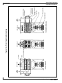
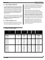
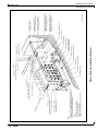
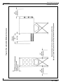
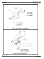
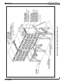
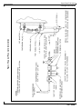
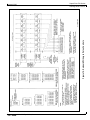
Supra-Pulse FJH Series
Cartridge Dust Collector
Owner’s Manual
KNOW YOUR EQUIPMENT
READ THIS MANUAL FIRST.
Your DUST-HOG system should provide many years of trouble-free service. This manual will
help you understand its operation, tell you how to obtain top performance, and show you how to
maintain your DUST-HOG unit. Finally, for quick future reference, fill in the system and filter
information in the spaces below. Should you need assistance, call the DUST-HOG factory service
number shown below. Make certain you have the information below before calling.
UAS ORDER #: _________________________________________________________________
UNIT MODEL #: ________________________________________________________________
UNIT SERIAL #: ________________________________________________________________
CARTRIDGE FILTER PART #: ____________________________________________________
SYSTEM ACCESSORIES:
______________________________________________________________________________
______________________________________________________________________________
______________________________________________________________________________
INSTALLATION DATE: __________________________________________________________
DUST-HOG CUSTOMER SERVICE
1-800-252-HOGS
TABLE OF CONTENTS
1.
Page
IMPORTANT NOTICE ...................................................................................... 1
1.1 General Cautions ................................................................................................................ 1
2.
INTRODUCTION .............................................................................................. 1
2.1 Unit Nomenclature .............................................................................................................. 1
2.2 Description and Operation .................................................................................................. 1
2.3 Air Filtering Operation ......................................................................................................... 3
2.4 Filter Cleaning Cycle .......................................................................................................... 3
3.
SPECIFICATION TABLE ................................................................................... 3
4.
INSTALLATION ................................................................................................. 4
4.1 Off Loading and Inspection ................................................................................................. 4
4.2 Installation Planning ........................................................................................................... 4
4.3 Assembling of Standard Equipment ................................................................................... 7
4.4 Assembly of Optional Equipment .................................................................................... 10
4.5 Compressed Air Connection ............................................................................................ 12
4.6 Electrical Installation ........................................................................................................ 13
5.
6.
OPERATION ................................................................................................... 21
5.1 Start Up ............................................................................................................................ 21
5.2 Checklist .......................................................................................................................... 22
5.3 Checking the Pulse Cleaning System with your Controller ............................................. 22
5.4 Operating Adjustments .................................................................................................... 22
SERVICE ........................................................................................................ 23
24
24
24
24
25
25
6.1 Cartridge Filter Removal and Replacement ....................................................................
6.2 Cartridge Filter Seeding Procedures ...............................................................................
6.3 Dust Removal ..................................................................................................................
6.4 Servicing the Compressed Air Components ...................................................................
6.5 Servicing the Direct Drive Motor and Fan .......................................................................
6.6 Servicing Optional Return Air Safety Filters/HEPA Filters ..............................................
7.
8.
TROUBLESHOOTING GUIDE ...................................................................... 26
ILLUSTRATED PARTS ................................................................................... 28
29
30
31
32
FJH-1 Series ..........................................................................................................................
FJH-2 Series ..........................................................................................................................
FJH-3 Series ..........................................................................................................................
FJH-4 Series ..........................................................................................................................
Warranty ...........................................................................................Back Cover
Supra-Pulse FJH Series
Cartridge Dust Collector
Revised 02/02
1. IMPORTANT NOTICE
This manual contains important safety information and
precautionary measures. It is impossible to list all
potential hazards associated with every dust collection
system in each application. Proper use of the equipment
must be discussed with United Air Specialists, Inc.
(UAS) or your local DUST-HOG® representative.
Operating personnel must be aware of, and adhere to,
the most stringent safety procedures.
!
WA R N I N G
A warning symbol means people may be injured if the
procedures are not followed.
!
C AU T I O N
A caution symbol is used when equipment could be
damaged if the procedures are not followed.
1.1
GENERAL CAUTIONS ON USING DUST
CONTROL EQUIPMENT
1. Avoid mixing combustible materials such as
aluminum, paper, wood or other organic dusts, with
dusts generated from grinding or welding metals. A
fire hazard could develop from sparks entering the
dust collector. When collecting flammable or
explosive materials, the dust collector should be
located outdoors and incorporate the appropriate
safety measures and/or accessories.
2. When collecting emissions from spark-producing
processes, care must be taken to reduce any
potential fire hazards. System design should include
methods to prevent sparks from entering the dust
collector. Dust collectors do not contain fire
extinguishing equipment unless specifically ordered.
Experts in the field of fire extinguishing equipment
should be consulted for recommendations
concerning proper fire detection and suppression
systems.
2. INTRODUCTION
Thank you for selecting DUST-HOG dust collection
equipment to assist you in your commitment to a clean
and safe environment. We trust in purchasing our
product you have recognized our commitment to
continually offer dust collection equipment engineered to
each dust collection need and manufactured to the
highest quality standards.
The Supra-Pulse Cartridge Dust Collector is designed
to collect process-generated dusts. The Supra-Pulse
provides continuous-duty cleaning and operation in its
application to improve the work environment.
2.1 UNIT NOMENCLATURE
EXAMPLE: FJH 24-3-H
FJH — DUST-HOG Supra-Pulse
cartridge dust collector
24 — number of cartridge filters
3
— number of filters tiers
H
— unit base arrangement
(hopper base includes one hopper
outlet per module)
2.2 DESCRIPTION AND OPERATION
The Supra-Pulse is a high efficiency, cartridge dust
collector designed to eliminate airborne dust as it is
generated. Contaminants are captured at the source(s),
then conveyed through ductwork to the cartridge filter
section where the dust is collected. Clean air is then
discharged from the unit.
There are two primary modes of operation. These are
the air filtering operation and the filter cleaning cycle as
shown in Figure 1.
3. Some dust collection systems require explosion
venting. Consult your insurance underwriter, NFPA
(National Fire Protection Association) Manual and
your local fire authorities to determine the
requirements for explosion venting.
4. Be careful and conscientious — consult national and
local fire codes, waste disposal, safety and other
appropriate authorities and comply with their
recommendations for the proper installation and
operation of dust collection equipment.
United Air Specialists, Inc.
1
Supra-Pulse FJH Series
Cartridge Dust Collector
Figure 1. Air Filter Operation & Cleaning
Revised 02/02
2
United Air Specialists, Inc.
Supra-Pulse FJH Series
Cartridge Dust Collector
Revised 02/02
2.3 AIR FILTERING OPERATION
The contaminated airstream is drawn into the collector
where its velocity is reduced by an inlet baffle plate(s) to
provide even distribution of the airstream across the
entire surface area of the cartridge filters. This design
enhances filtration efficiency by establishing a uniform
“dust cake” on the filters. The airstream is then directed
around the cartridge filters and downward toward the
hopper where the heavier particles discharge to the
storage container.
The contaminated air then passes through the cartridge
filters. The filter media strips the dust from the airstream
allowing only clean air to pass through the filter. The air
then passes into the clean air plenum, and is
discharged from the unit.
2.4 FILTER CLEANING CYCLE
During normal operation, the surface of the cartridge
filters becomes loaded with contaminants. The reverse
pulse cleaning mechanism provides brief bursts of
compressed air, directed through cleaning nozzles, into
the interior of the cartridge filters. This pulsing action
dislodges the collected particles from the media where it
falls into the hopper and is discharged to the dust
storage container.
During the cleaning cycle, each cartridge filter is
cleaned individually. The solid-state sequential timer
actuates a solenoid valve which allows an air diaphragm
valve to open for approximately 100 milliseconds. High
pressure air from the air manifold reservoir is directed
through a cleaning nozzle to the cartridge center. The
quick blast of compressed air induces additional air from
the clean air plenum which combine to produce a shock
wave, dislodging the dust from the filter being cleaned.
The dislodged dust removed from the filter is swept
downward into the hopper. The remaining filters are
cleaned sequentially. The sequencing is factory set at
10-second intervals and is adjustable to adapt to your
particular cleaning needs.
3. SPECIFICATION TABLE
Supra-Pulse
Model
Filter
Quantity
Filter Area
FT2
Valve
Quantity
Module
Quantity
Equipment
Weight,
4
8
16
24
32
12
24
36
48
60
72
16
32
48
64
80
96
112
128
904
1,808
3,616
5,424
7,232
2,712
5,424
8,136
10,848
13,560
16,272
3,616
7,232
10,848
14,464
18,080
21,696
25,312
28,928
2
4
8
12
16
6
12
18
24
30
36
8
16
24
32
40
48
56
64
1
1
2
3
4
1
2
3
4
5
6
1
2
3
4
5
6
7
8
1,560 lbs
1,830 lbs
3,127 lbs
4,424 lbs
5,809 lbs
2,100 lbs
3,559 lbs
5,018 lbs
6,565 lbs
8,024 lbs
9,483 lbs
2,370 lbs
3,993 lbs
5,616 lbs
7,327 lbs
8,950 lbs
10,573 lbs
12,284 lbs
13,907 lbs
FJH 4-1-H
FJH 8-2-H
FJH 16-2-H
FJH 24-2-H
FJH 32-2-H
FJH 12-3-H
FJH 24-3-H
FJH 36-3-H
FJH 48-3-H
FJH 60-3-H
FJH 72-3-H
FJH 16-4-H
FJH 32-4-H
FJH 48-4-H
FJH 64-4-H
FJH 80-4-H
FJH 96-4-H
FJH 112-4-H
FJH 128-4-H
United Air Specialists, Inc.
3
Supra-Pulse FJH Series
Cartridge Dust Collector
Revised 02/02
4. INSTALLATION
4.1 OFF LOADING AND INSPECTION
Supra-Blast dust collector modules are shipped
assembled on a skid(s). Other skids will contain the
hopper/leg assembly and other components. Other
accessories (afterfilter assemblies, blower packages,
dust storage drums, silencers, etc.) may be on
additional, separate skids.
!
C AU T I O N
Lift the dust collector components by the packing
skids or use the external lifting lugs provided on the
filter module. Do not lift the filter module of the dust
collector by placing lift truck forks through the
cartridge filter access doors. The filter support rails or
the conical air distribution tips installed on the
tubesheet could be damaged.
Upon receipt of your unit, check for any shipping
damage. A damaged carton indicates that the
equipment may have received rough handling during
shipping that may have caused internal damage. Notify
your delivery carrier and enter a claim if any damage is
found.
4
4.2 INSTALLATION PLANNING
The proper location of your dust collection equipment is
very important. Refer to Figure 2 for typical installation
details.
Certain items should be considered when locating the
unit, such as emptying of the dust storage container(s),
filter removal requirements, compressed air and
electrical connections, and fan discharge direction. The
shortest duct length with a minimum number of elbows
will maximize the performance of the unit. Ease of
maintenance should also be considered when selecting
the location and orientation of the system
(see Figure 3).
In the case of spark producing processes, system
design should incorporate measures to prevent live
sparks from entering the dust collector. Consult local
authorities for the location of this unit and any additional
precautions to consider when collecting combustible,
explosive or hazardous dusts. (See General Cautions on
page 1.)
The Supra-Pulse Dust Collector is usually mounted on a
reinforced concrete foundation. Other mounting options
are also possible. Structural calculations for the
foundation or other mounting arrangements must
include the weight of the collected material and the
weight of all auxiliary equipment. These weights must be
considered together with wind, seismic and other live
load ratings when designing the support structure. See
the Specification Table on page 3 for dust collector unit
weights.
United Air Specialists, Inc.
Supra-Pulse FJH Series
Cartridge Dust Collector
Figure 2. Typical Installation Diagram
Revised 02/02
United Air Specialists, Inc.
5
Supra-Pulse FJH Series
Cartridge Dust Collector
Figure 3. Recommended Minimum Clearance
Revised 02/02
6
United Air Specialists, Inc.
Supra-Pulse FJH Series
Cartridge Dust Collector
Revised 02/02
4.3 ASSEMBLING OF STANDARD EQUIPMENT
!
C AU T I O N
Use adequate safety measures when lifting and
assembling any heavy components. Consult your
plant safety personnel for recommendations.
Remove all crating, strapping and hold-down
bolts. Locate all hardware bags, silicone sealant and
other assembly materials provided with your unit.
FULLY WELDED MODULE SECTIONS
Position legs as shown in “Plan Detail” on unit sales
drawing. Bolt on sway braces using hardware as shown.
Leave all hardware hand-tight only; shim legs as
required (see Figure 4).
Secure leg assemblies to concrete mounting pad with
appropriate anchoring hardware. Anchors should be
provided by customer and contractor according to local
codes.
Fit hopper over leg assemblies, positioning the corner
holes of hopper over alignment pins in each leg gusset
corner. Apply two ribbons of sealant to hopper flange to
create “figure 8” pattern around mounting holes (see
Figure 5).
!
C AU T I O N
In preparing to assemble the filter cabinet to the
hopper, connect a lifting sling to the four cabinet
lifting lugs with clevis pins. Distribute the load evenly.
Location must be clear of all obstructions such as
utility lines or roof overhangs.
Place cabinet onto hopper/leg assemblies, positioning
cabinet corner holes over alignment pins in leg gussets.
With cabinet still supported, use hardware (refer to
Figure 5) to bolt hopper and cabinet together. Securely
tighten all hardware at cabinet/hopper and leg assembly
sway braces. Remove lifting sling.
MULTIPLE, BOLT-TOGETHER
MODULE SECTIONS
For units that have multiple, bolt-together module
sections, remove the row of filters (see Section 6.1)
from the modules nearest the bolt flange and locate out
of the way in a safe area. Identify the different module
sections. There is a left (bolt flange on the right side), a
right (bolt flange on the left side) and, possibly, center
(bolt flange on both sides) module sections.
United Air Specialists, Inc.
Position legs as shown in the “plan detail” as described
earlier. Bolt on sway bracing hand tight (refer to Figure
4) and level as required. Fit hopper over the leg
assemblies, positioning the corner holes of the hoppers
over alignment pins in each leg gusset corner. Starting
with the hopper that is furthest away, apply two ribbons
of sealant to its flange creating a “figure 8” pattern
around the mounting holes (see Figure 5).
!
C AU T I O N
In preparing to assemble the filter cabinet to the
hopper, connect a lifting sling to the four cabinet
lifting lugs with clevis pins. Distribute the load evenly.
Location must be clear of all obstruction such as utility
lines or roof overhangs.
Place the appropriate module section onto the hopper to
which the sealant has been applied using the same
corner alignment pins for proper positioning. Drift pins
will also be useful for locating module sections onto the
hopper. With the module still supported, use hardware
(refer to Figure 5) to bolt the hopper and cabinet module
together. Fully tighten the hardware on legs, bracing,
anchors and hopper for this module section only.
Disconnect the crane.
Apply sealant to the next hopper to receive a cabinet
module. Apply sealant to the bolt flange of the first
module using the “figure 8” pattern (see Figure 5). Place
this module on its hopper using the same technique as
described above, leaving the hopper hardware handtight. As the bolt flanges are aligned, take care not to
wipe off the sealant from the flange. Drift pins will be
useful in this alignment process. Use the hardware
provided (refer to Figure 6) and bolt the module sections
together. Use all bolt holes. Tighten the bolt flange
hardware securely. With the module section still
supported by the crane, tighten the other hardware
connections securely at the hopper and legs.
Disconnect the crane.
Repeat this process until all the module sections are in
place and securely fastened. Recheck all hardware
connections to make sure that they are securely
tightened. Remove all connections from the crane and
clear all tools from the work area.
NOTE: Make certain all bolts (including the anchor
bolts) are properly tightened before proceeding
with the remainder of the installation.
7
Supra-Pulse FJH Series
Cartridge Dust Collector
Revised 02/02
Figure 4. Typical Sway Brace Installation
Figure 5. Corner Alignment Detail
8
United Air Specialists, Inc.
Supra-Pulse FJH Series
Cartridge Dust Collector
Figure 6. Multiple, Bolt-Together Module Sections
Revised 02/02
United Air Specialists, Inc.
9
Supra-Pulse FJH Series
Cartridge Dust Collector
Revised 02/02
4.4 ASSEMBLY OF OPTIONAL EQUIPMENT
FAN PACKAGE INSTALLATION
If a top-mount fan was ordered, remove the clean air
plenum cover plate and save the mounting hardware.
Ensure Teflon® ribbon gasket remains on the unit. Lift
fan package using safe, suitable means and position fan
base holes over cabinet holes with fan discharge
pointing in the desired direction. Secure with bolt/
washer assemblies previously removed.
If the fan package is a ground-mount fan, follow
manufacturer’s recommendation for installation. The
installation manual is attached to the fan package.
Outlet ductwork from the Supra-Pulse unit to the fan can
be connected to either the top or bottom access panel.
Panels which are not used as clean air discharge
connection points will serve as inspection ports.
The bottom access panel and its gasket are shipped
loose with installation hardware. If the bottom access is
not to be used for discharge ductwork, attach the panel
to the bottom opening using the hardware provided.
DUCT SILENCER INSTALLATION
A duct-type silencer is designed to bolt directly to the
fan outlet damper flange. Make certain there is
adequate room for the silencer in the discharge direction
and provide at least 24" of unobstructed space at the
discharge end of the silencer. The air discharge should
be directed into an open area free of obstructions and
with consideration for personnel safety.
!
C AU T I O N
Do NOT use the fan damper flange to support the
silencer.
The silencer will require separate support. Apply silicone
around the bolt holes of the connecting flanges, lift the
silencer into position and secure with the hardware
provided. Install permanent supports (not supplied by
UAS) and tighten all hardware before removing the
lifting device.
Remove all packing from the rotary air lock and
determine its appropriate position. Keep in mind
required clearances, electrical connections and
maintenance requirements. Apply sealant to the flange
of the rotary air lock and fasten to the adapter using 3/8"
bolts, nuts, washer and lock washers.
All electrical connections should be made by a qualified
electrician according to all applicable codes. Refer to the
nameplate and/or documentation attached to the rotary
air lock for voltage, amperage, cycle and proper wiring.
!
C AU T I O N
Disconnect all power to the rotary air lock before
servicing. There are moving parts on the rotary air
lock. Do not allow any object to be placed in or near
the rotary air lock during operation.
ABRASIVE RESISTANT INLET INSTALLATION
The abrasive resistant inlet is designed to use the front
access(es) of the Supra-Pulse modules as the inlet area
to the unit. There are three styles available: the single,
dual or triple module abrasive resistant inlet. Each is
designed to fit over the appropriate number of front
accesses to serve as a single inlet point for one to three
modules (see Figure 7).
Remove the front access plate(s) located above the
filter access doors. Save the hardware; this will be used
to attach the abrasive resistant inlet. Remove any
remaining gasket material from around the perimeter of
the opening.
Apply a 1/4" bead of sealant around the perimeter of the
access opening. Clean out if required for maintenance. If
the bottom plate is removed, carefully remove the ribbon
of Teflon sealant and reuse after cleaning the gasket
surfaces. The bottom plate on the abrasive inlet will
serve as an inspection plate. Clean out if required for
maintenance. If the bottom plate is removed, carefully
remove the ribbon of Teflon sealant and reuse after
cleaning the gasket surfaces.
ROTARY AIR LOCK INSTALLATION
If a rotary air lock was ordered with the unit, the hopper
discharge will have an adapter already bolted to it.
Ensure that the bolts connecting the adapter to the
hopper discharge are securely tightened.
10
United Air Specialists, Inc.
Supra-Pulse FJH Series
Cartridge Dust Collector
Revised 02/02
Figure 7. Abrasive Resistant Inlet Installation
DRUM LID INSTALLATION
Remove the drum lid package from its shipping carton.
Place the drum lid on a 55-gallon drum (optional). Slide
the 14" hose over the drum lid and secure with a hose
clamp. Position the drum assembly under the unit, slide
the hose up onto the discharge adapter collar on the
hopper and secure with a hose clamp.
If a drum lid latch kit was ordered, attach the separate
clamp band around the 55-gallon drum, leaving the
cinch bolt loose. Position the three latch pawls onto the
drum lid catches, rotating the drum lid as required.
Tighten the cinch bolt and adjust the latch tension and/
or band placement as required (see Figure 8).
If a slide gate was ordered, it was factory installed on
the hopper. Open the slide gate. Repeat for multiple
drum lid connections.
NOTE: The hopper is not designed for dust storage.
The slide gate should remain open during
normal operation.
Figure 8. Drum Lid Installations
United Air Specialists, Inc.
11
Supra-Pulse FJH Series
Cartridge Dust Collector
Revised 02/02
MAGNEHELIC® GAGE INSTALLATION
If your system was ordered with a Magnehelic Gage,
remove it and the hardware from the box. Instructions
for mounting and connecting the Magnehelic Gage are
provided from the manufacturer. Follow these instructions
using the hardware provided. It should be installed
within sight of the Supra-Pulse as shown in Figure 2.
NOTE: The hardware provided is designed for surface
mounting of the Magnehelic Gage. Be certain
to install the 1/8" NPT pipe plugs in the
pressure ports on the back of the gauge.
Install the tube fittings in the pressure ports on the side
of the gauge. Mount it to the bracket and the bracket to
a support structure.
PHOTOHELIC® GAGE INSTALLATION
If your system was ordered with a Photohelic Gage,
remove it and the hardware from the box. Instructions
for mounting and connecting the Photohelic Gage are
provided from the manufacturer. Follow these
instructions using the hardware and UAS mounting
bracket provided. The Photohelic Gage and mounting
bracket should be installed within sight of the SupraPulse as shown in Figure 2. Hardware to mount the
bracket to the support structure is not supplied by UAS.
NOTE: Be certain to install the two jumper wires (not
supplied by UAS) as shown in the instruction
manual provided with the gauge. Also see
Figure 11.
SUPRA-CLEAN TIMERBOARD INSTALLATION
Your system comes standard with a Supra-Clean timer
control for sequence pulse cleaning of your cartridge
filters. The timer should be installed within sight of the
Supra-Pulse as shown in Figure 2. Hardware to mount
the panel to the support structure is not supplied by UAS.
SUPRA-VIEW PANEL INSTALLATION
If your system was ordered with a Supra-View control
panel, remove panel and hardware from the box. The
panel should be installed within sight of the Supra-Pulse
as shown in Figure 2. Hardware to mount the panel to the
support structure is not supplied by UAS. Refer to the
Supra-View Owner’s Manual for proper installation details.
SUPRA-I.Q. DIAGNOSTICS PANEL
INSTALLATION
If your system was ordered with a Supra-I.Q.
diagnostics panel, please refer to the Supra-I.Q.
Owner’s Manual for proper installation details.
12
FINAL CONNECTIONS FOR ALL GAUGE
OPTIONS
For any control system, connect the black, plastic
pressure tubing (25 feet provided by UAS) to the gauge
or panel fittings and the Supra-Pulse. Connect the dirty
air plenum on the Supra-Pulse to the high pressure port
on the gauge or panel and the clean air plenum on the
Supra-Pulse to the low pressure port on the gauge or
panel as shown in Figure 10. Zero, calibrate and maintain
the gauge as recommended by the manufacturer on the
instructions provided with the gauge.
4.5 COMPRESSED AIR CONNECTION
!
C AU T I O N
Do NOT allow water and/or oil from the compressed
air system into the compressed air manifold on the
Supra-Pulse. To ensure a water-free air supply,
especially when the unit is installed outdoors, a water
filter with automatic drain or a condensate trap with
automatic drain must be installed just before the piping
enters the Supra-Pulse (see Figure 9).
Clean, dry, 90-110 PSIG compressed air is required for
the pulse cleaning system to properly function. Compressed air consumption is noted on the unit sales drawing. A shut-off valve, pressure regulator and pressure
gauge should be installed close to the Supra-Pulse unit.
UAS recommends dedicated oil and water removal filters
be used to ensure clean, dry air is delivered to the pulse
system. Contact your local DUST-HOG representative for
information on the UAS pneumatic valve kit. See Figure 9
for recommended compressed air piping.
NOTE: A 1" diameter or larger compressed air supply
pipe is required.
Provide 1" minimum compressed air line piping to the
unit. The pipe diameter should be based on the main
line pressure, length of pipe run and number of pipe
bends from the main line to the unit. The pipe
connection for the Supra-Pulse unit is located on the
bottom of the air reservoir manifold(s) on the back of the
module(s) as shown in Figure 2. The connection size is
a female 1" NPT fitting.
NOTE: Purge the compressed air line to remove any
debris prior to making the final connection to
the Supra-Pulse compressed air mainifold(s).
Remove the plastic plug from the Supra-Pulse air
manifold(s) prior to making the final compressed air pipe
connection. Apply pipe sealant to ensure a leak-free
connection.
United Air Specialists, Inc.
Supra-Pulse FJH Series
Cartridge Dust Collector
Revised 02/02
4.6 ELECTRICAL INSTALLATION
!
C AU T I O N
All electrical work should be performed by a qualified
electrician in accordance with local electrical codes.
Disconnect electrical power before installing or
servicing any electrical component.
GENERAL
Several types of standard electrical components can be
installed to control and monitor your dust collector
ensuring proper cleaning of the cartridge filters. A fan
motor starter circuit is required to start and stop the
system. The motor starter circuit should consist of a
properly-sized, fused disconnect or circuit breaker,
contractor and overload relay for short circuit and
overload protection of the blower package. A 115/1/60
low voltage (2 amp) control circuit is required for the
pulse cleaning controls. Any one of the following control
configurations can be used (refer to Figures 11 - 13 for
wiring schematics):
•
Motor starter with Supra-Clean timerboard for
continuous pulse (Magnehelic Gage). See Figure 11
for recommended wiring.
•
Motor starter with Supra-Clean timerboard for
setpoint pulse (Photohelic Gage). See Figure 11 for
recommended wiring.
•
Motor starter with Supra-View Panel for self
contained differential pressure display, pulse control
and alarm. See Figure 12 for recommended wiring.
•
Motor starter with Supra-I.Q. Diagnostics Panel for
complete monitoring and automated pulse control.
See Figure 13 for recommended wiring.
Refer to UAS sales order to verify the control
configuration purchased with your unit.
MOUNTING OF THE CONTROLS
Mount the motor starter for the fan motor control in a
convenient location. The motor starter is provided by the
customer, unless specifically ordered from UAS.
Mounting hardware for a UAS starter panel is provided
by the customer or contractor.
Mount the solid-state cleaning controls (Supra-Clean,
Supra-View or Supra-I.Q.) in a convenient location. It is
recommended that the controls be mounted on a wall or
pedestal in a convenient area subject to minimal
vibration and electrical noise.
United Air Specialists, Inc.
!
C AU T I O N
Avoid mounting the Supra-Clean, Supra-View and
Supra I.Q. Panel on the collector due to vibration
generated from the blower assembly and the pulsing
system.
PULSE CLEANING CONTROLS
For a more in-depth explanation of the cleaning control
features and options, refer to Section 5 or the
Installation and Operation Manual supplied with the
Supra-Clean timerboard, Supra-View Panel or SupraI.Q. Diagnostics Panel.
SOLENOID VALVE ENCLOSURE WIRING
The solenoid valves at the dust collector must be wired
correctly to the pulse controls. Refer to Figure 14 when
making connections from the pulse controls (SupraClean timerboard, Supra-I.Q. Diagnostics Panel) to the
solenoid valve enclosure(s).
Example: Figure 14 shows the FJH-8 having eight valve
locations per module. This means when the system
pulses, “1” is the first pulse in the sequence, “2” is the
second, “3” is the third, etc.
When multiple dust collector modules are installed, daisy
chain the wiring so that each solenoid valve with the
same module location will pulse at the same time. This
means all #1 solenoid valves are tied together and wired
to pulse controller “OUT 1”, and #2 solenoid valves are
tied together and wired to pulse controller “OUT 2”, etc.
Refer to Figure 14 for the FJH dust collector solenoid
valve wiring information. When cleaning, the pulse valves
sequence left to right, top to bottom.
Unless specified on the UAS sales order, the customer
will supply interconnecting material (conduit, wiring,
etc.) from the pulse controls to the dust collector.
HEATER WIRING
In cold or damp environments, the heater serves to
prevent the electric solenoid valves from freezing due to
cold temperatures or condensation. If optional solenoid
valve heaters are purchased, each solenoid valve
enclosure will contain a 100-WATT cartridge heater
internally prewired to a thermostat.
The customer must supply a separate, 100-130VAC, 5060Hz, 1 amp supply power to the heater circuit for each
module. The supply must be available to the module
solenoid valve enclosure(s) at all time (even when the
blower is shut down) to ensure that the temperature regulation inside each solenoid valve enclosure is continual.
13
Supra-Pulse FJH Series
Cartridge Dust Collector
Figure 9. Typical Pneumatic Installation
Revised 02/02
14
United Air Specialists, Inc.
Supra-Pulse FJH Series
Cartridge Dust Collector
Figure 10. Pressure Gage Installation Diagram
Revised 02/02
United Air Specialists, Inc.
15
Figure 11. Power and Elementary Wiring for Units with Supra-Clean Timerboard and Magnehelic/Photohelic Control
Revised 02/02
16
Supra-Pulse FJH Series
Cartridge Dust Collector
United Air Specialists, Inc.
Supra-Pulse FJH Series
Cartridge Dust Collector
Figure 12. Power and Elementary Wiring for Units with Supra-View Panel
Revised 02/02
United Air Specialists, Inc.
17
Supra-Pulse FJH Series
Cartridge Dust Collector
Figure 13. Power and Elementary Wiring for Units with Supra-I.Q. Diagnostics Panel
Revised 02/02
18
United Air Specialists, Inc.
Supra-Pulse FJH Series
Cartridge Dust Collector
Figure 14. Solenoid Wiring to Pulse Controls
Revised 02/02
United Air Specialists, Inc.
19
Supra-Pulse FJH Series
Cartridge Dust Collector
Figure 15. Supra-Pulse Cartridge Filter Installation / Removal
Revised 02/02
20
United Air Specialists, Inc.
Supra-Pulse FJH Series
Cartridge Dust Collector
Revised 02/02
When multiple module solenoid valve enclosures with
heaters are installed, daisy chain the wiring so that each
heater will have 100/115/VAC, 50/60Hz at all times. Make
certain enough current is available to supply all heaters.
Example: If three solenoid valve enclosures are
supplied with cartridge heaters, make certain the
voltage supply can deliver 3 amps (1 amp per heater).
5. OPERATION
!
C AU T I O N
Shut off unit disconnect and lock out all electrical
power to the dust collector prior to performing
service work.
!
C AU T I O N
Prior to unit start-up, all installation set-up instructions
must be completed as specified by this manual,
Supra-Clean Installation and Operation Manual,
Supra-View Installation and Operation Manual, SupraI.Q. Installation and Operation Manual, as well as any
manuals supplied by other equipment manufacturers,
as they apply to your dust collector.
!
C AU T I O N
The blower assembly provided by United Air
Specialist, Inc. includes an outlet damper. If the blower
assembly was purchased separately, ensure a volume
control damper is included somewhere in the dust
collection system. Close the blower discharge damper
to 50% open position and tighten in place. If a volume
control damper is provided in another part of the dust
collection system, adjust second damper to the 50%
open position and tighten in place.
NOTE: It is important that the air volume of the dust
collection system is at design conditions at
system start-up. There is a minimal pressure
differential across new cartridge filters. If the
volume control damper is not correctly
adjusted, the air volume will be above design
conditions for airflow and may affect the
cartridge filter life.
!
C AU T I O N
Verify dust collector system airflow is adjusted to
design conditions with new, clean filters using the
volume control dampers installed in the system.
Failure to properly adjust system airflow may affect
cartridge filter life.
5.1 START UP
Inspect the installation area and make certain no tools,
parts, etc. have been left anywhere on or inside the FJH
unit. Check blower discharge to make certain it is free
from all debris.
Start motor/blower and check for proper rotation. A
rotation arrow is located on the blower housing. All topmount blower assemblies rotate in a clockwise rotation
as viewed from the driven end (motor end with motor
cooling fan). If the blower is rotating in the opposite
direction, disconnect the power to the motor starter. For
3-phase blowers, interchange any two power wires to
the motor at the load side of the motor starter contactor.
For single-phase power, refer to motor nameplate for
which two wires to interchange at motor junction box.
Engage starter disconnect, start blower and recheck
rotation.
NOTE: Proper blower rotation is required to move the
designed amount of air. A blower rotating in the
incorrect direction will only move about 40% of
design airflow.
United Air Specialists, Inc.
The air volume should be adjusted based on the
performance of the entire system. Air volume control
damper should be adjusted to the system design
conditions. Closing the volume damper decreases
system airflow. Opening the volume damper increases
system airflow.
On certain applications, it may be beneficial to “seed” or
pre-coat the original or replacement cartridge filters.
This process introduces a certain amount of coating
(usually crushed limestone, agricultural lime or other
specifically marketed pre-coat) in light concentration to
deposit a thin coating of material which acts as an aid to
filtration. This deposited dust cake keeps the dust
loading on the surface of the cartridge filter. This
process will increase filter life and efficiency while
allowing the cleaning system to work more effectively.
For filter seeding procedures, refer to Section 6.2.
Turn on the compressed air supply to the dust collector
air manifold reservoir. Adjust the pressure regulator until
the gauge reads 90-110PSIG (6.2-7.6BAR).
21
Supra-Pulse FJH Series
Cartridge Dust Collector
Revised 02/02
5.2 CHECKLIST
•
If your system is supplied with a Supra-Clean
timerboard (with Magnehelic or Photohelic Gage) or
Supra-View Panel, place the “Continuous Clean/PS”
switch on the timerboard to the “Continuous Clean”
position. The MOT AUX terminals at the timerboard
must have continuity for the pulsing to become
active. Energize the motor starter coil to close the
isolated auxiliary contact wired to the timerboard
MOT AUX terminals. Verify robust and consistent
pulse firing of each valve.
•
If your system is supplied with a Supra-I.Q.
Diagnostics Panel, place the system in “Continuous
Clean” by entering Code 5. At the “SET MODE” state
enter “1” for Continuous cleaning. Terminals 1 and 2
at terminal strip P7 must have continuity for the
cleaning system to activate. This can be done by
placing a temporary jumper across 1 and 2 to
activate the cleaning sequence. Please allow 45
seconds after panel power up for pulsing to start as
the Supra-I.Q. cleaning mode(s) operate on a delay.
Verify robust and consistent pulse firing of each
valve. When test is complete, enter code 5 and at the
“SET MODE” state enter “2” for Autotune cleaning
mode.
Check the discharge of the blower assembly. Initially,
some dust may discharge from the blower assembly
as the filters are seasoned. This may last several
minutes after which the discharge air should remain
visibly clean.
Measure the total airflow and static pressure at the inlet
to the Supra-Blast unit. Adjust the blower outlet damper
for the desired airflow. Check to ensure that adequate
air is being drawn into each of the collection points of
the system. Adjust the individual dampers for each
operation to balance the system airflow. Recheck the
total system airflow and adjust the blower damper to
desired system airflow. This procedure may need to be
repeated several times until the entire system is within
system design airflow specifications.
Check the differential pressure reading across the dust
collector clean-to-dirty air sections. A normal differential
pressure drop reading is between 1"-6" w.g.
(25-152mmAq). At start-up, this reading is generally
in the 1"-3" w.g. (25-76mmAg) range. Please list the
reading here for future reference.
Initial dust collector differential pressure reading across
filters is ________ " w.g. or (________mmAg) on
_________ (date).
NOTE: If your system is controlled by the Supra-I.Q.
Diagnostics Panel, the yellow air flow alert light
may be illuminated. This is normal until the “Air
Flow Calibration” routine has been performed
at the Supra-I.Q. Diagnostics Panel. This must
be performed during start-up of your collection
system once all of the inlet(s) and duct work is
in place and the outlet damper (if required) is
opened 75%. Refer to the Supra-I.Q.
Installation and Operation Manual and perform
the “Code 4 - Air Flow Settings” steps.
5.3 CHECKING THE PULSE CLEANING
SYSTEM WITH YOUR CONTROLLER
Check the cleaning system for proper operation. The
Compressed air pressure should be between 90110PSIG (6.2 - 7.6BAR). The Supra-Clean, Supra-View
and Supra-I.Q. panels are factory set to pulse every 10
seconds. Refer to the Supra-Clean, Supra-View or
Supra-I.Q. Installation and Operation Manual to change
these initial settings. Check to ensure the pulse
(diaphragm) valves are “firing” at approximately 10second intervals and deliver a crisp sounding pulse to
each filter. The valves should not deliver a weak or
lingering pulse. To check the pulse sequence for proper
firing, perform the following:
22
5.4 OPERATING ADJUSTMENTS
Please confirm the type of pulse cleaning controller
delivered with your system. Your system was delivered
with one of the following types:
• Magnehelic Gage with Supra-Clean timerboard
• Photohelic Gage with Supra-Clean timerboard
• Supra-View Pulse Panel
• Supra-I.Q. Diagnostics Panel
NOTE: It is important that the compressed air pressure
in the manifold is above 90 PSIG immediately
prior to a pulse. If the delivery capability of your
compressed air source cannot return the
manifold pressure to above 90 PSIG during the
“Pulse Delay” (time between pulses) interval,
adjust the pulse delay at the timerboard or
Supra-I.Q. Panel and monitor the pressure
drop. A longer interval will raise the operating
differential pressure and a shorter will interval
will lower the operating differential pressure.
Allow sufficient time for the system to stabilize
after each adjustment before further
adjustment is made. Adjust until the desired
pressure differential is reached.
United Air Specialists, Inc.
Supra-Pulse FJH Series
Cartridge Dust Collector
Revised 02/02
MAGNEHELIC GAGE CONTROL WITH
SUPRA-CLEAN TIMERBOARD
When using a Magnehelic Gage with Supra-Clean
pulse timerboard, the timerboard is always set to
“Continuous Clean” pulse mode. If the filters are
operating at a higher or lower differential pressure than
desired, adjusting the pulse frequency (Pulse Delay)
can often modify the steady-state pressure differential.
The factory setting is 10-second intervals. Adjust the
“Pulse Delay” on the Supra-Clean timerboard and
monitor the pressure drop on the Magnehelic Gage. A
longer interval will raise the operating differential
pressure and a shorter interval will lower the operating
differential pressure. Allow sufficient time for the system
to stabilize after each adjustment before further
adjustment is made. Adjust unit the desired pressure
differential is reached.
PHOTOHELIC GAGE CONTROL WITH
SUPRA-CLEAN TIMERBOARD
When using a Photohelic Gage with Supra-Clean pulse
timerboard, the timerboard can set to “PS” pulse mode
(pulse cleaning activated by the Photohelic control) or
“Continuous Clean” pulse mode to override the
Photohelic Gage. With the Photohelic Gage control, the
desired pressure differential can be maintained by
adjusting the high and low setpoints on the gauge.
Adjust the upper setpoint to the desired differential
pressure setting plus 0.25" (factory recommended
setting is 3"). Adjust the lower setpoint to the desired
setting minus 0.25" (factory recommended setting is
2.5"). This allows a 0.5" “deadband” and the pulse
system will maintain the desired differential pressure
(factory recommended operating point is 2.75"). If the
differential pressure remains above the desired
operating point, the pulse frequency can be increased
(shorter “Pulse Delay”) as previously described. The
high and low needle setpoints on the Photohelic Gage
can be adjusted as the filters season and continuous
pulsing occurs. Adjust both needles upward in 0.5"
increments until pulsing stops. Continue adjustments,
when required, until the high setpoint reaches 6". No
further adjustments should be made above 6" w.g.
SUPRA-VIEW PULSE PANEL
When using the Supra-View panel, the pulsing controls
can be set to “PS” pulse mode (“On-Demand” cleaning
similar to Photohelic control) or “Continuous Clean”
pulse cleaning. The Supra-View comes standard with a
cartridge differential measurement/display, pulse time
sequence controls and a “Customer usable” high
cartridge pressure alarm contact all in one enclosed
assembly. The high, low and alarm setpoints are
United Air Specialists, Inc.
adjusted by opening the enclosure door and adjusting
the appropriate selector switches for desired control.
Adjustments to the setpoints can only be done with the
door open. Refer to the Supra-View Installation and
Operation Manual for adjustment details, or look on the
inside of the Supra-View enclosure door for operating
instructions.
SUPRA-I.Q. DIAGNOSTIC PANEL
The Supra-I.Q. Diagnostics Panel can be set to operate
in Continuous Clean, Setpoint Clean (similar to
Photohelic control), or “Autotune” Clean mode. Autotune
mode is designed to conserve compressed air usage
while maintaining lowest possible cartridge differential
pressure. It allows the minimal amount of compressed
air usage while maximizing filter life. In Autotune mode,
the controller will automatically adjust the filter
differential pressure to obtain the most cost-effective
setting. Please refer to the Supra-I.Q. Installation and
Operation Manual for a complete listing of operating
parameters and adjustment instructions.
ALL CONTROL OPTIONS
As filter cartridges become loaded with dust, the
differential pressure across the filters will increase. This
will result in a loss of air volume. Should the dust
collection capture effectiveness be reduced, open the
flow control damper to return the system to the original
design air volume.
6. SERVICE
BEFORE SERVICING,
NOTE THE FOLLOWING:
1. Disconnect electrical power to the unit and
control panel.
2. Shut off and slowly bleed compressed air supply
from the manifold.
3. Collected dust may be hazardous. Consult proper
authorities for handling and disposal.
4. Collected dust may be a potential fire hazard.
Welding, grinding or operations involving open
flames should NOT be performed without fire
protection measures in place. Refer to Section
1 of this manual for additional precautions.
5. Wear appropriate protective clothing when servicing
the dust collector.
6. Disposal of collected dust must be according to state
and local environmental regulations.
23
Supra-Pulse FJH Series
Cartridge Dust Collector
Revised 02/02
6.1 CARTRIDGE FILTER REMOVAL AND
REPLACEMENT (FIGURE 15)
The Supra-Series cartridge filters are the only
replacement filters that will provide the high level of
performance that is expected from the Supra-Pulse dust
collector.
Replacement cartridge filters should be ordered when
the differential pressure is consistently above 6" w.g. or
system airflow is inadequate. To order filters, call 1-800252-4647. The following procedure should be used to
replace the filters:
1. Start with the top access covers. Remove each
access cover by turning the knob counterclockwise.
Tilt cover back away from the unit when free from the
support yoke to trap any dust on the inside of the
access cover. Dispose of dust into a suitable
container. Set the cover aside.
2. Move the filter from side to side to break the gasket
seal between the filter and the tube sheet. Rotate the
filter 180 degrees to allow the dust on top of the
cartridge to fall into the dust collection hopper.
3. Slide the filter out of the unit along the support yoke
and transfer to a suitable disposal container. Repeat
this procedure for remaining filters.
4. Inspect the tube sheet and make certain the gasket
sealing area is free of dust to ensure proper sealing
of the new filter. Make certain the area is dry after
cleaning process is complete.
5. Install a new Supra-Series cartridge filter on each
support yoke, GASKET END first. Clean the access
cover gaskets and reinstall the cover onto the
support yoke. Tighten the knob until the outer door
gasket seats against the cabinet. Continue to tighten
the knob 1 1/2 turns. The maximum torque on the
door knob is 120 inch-pounds.
NOTE: The access cover must be securely tightened
to ensure compression of the filter gasket. Dust
leakage (bypass) can occur if the filter gasket is
not properly sealed.
6. The Supra-Pulse unit is now ready to be placed in
service. Reconnect electrical power and air supply.
Please follow initial start-up checklist to ensure
proper unit performance.
the cartridge filter initially. To begin seeding the filters,
turn the cleaning system “off,” then turn unit “on.”
Introduce the seeding material by slowly and gently
shaking the material next to an extraction hood or into
the drum lid opening (remove drum) where it can be
drawn into the unit. The seed material should be drawn
in as a continual “cloud,” trying to avoid any dust “slugs.”
Continue to feed the seeding material until the reading
on the filter monitor gauge increases by approximately
1" w.g. Replace the afterfilter, if applicable, and the dust
storage drum, if removed, before starting the unit.
6.3 DUST REMOVAL
NOTE: Do not let the dust storage drum overfill. This
can cause poor collector performance and
require an extensive clean-up due to overflow
of dust when removing the container(s).
Turn off the dust collector and empty the dust storage
drum an necessary to prevent dust from accumulating in
the hopper. Empty the dust storage drum when 2/3 full.
If the hopper has a slide gate, close the gate before
removing the dust storage drum. The collector fan does
not have to be shut off if this slide gate procedure is
followed. Remember to open the slide gate when the
dust storage drum is replaced.
6.4 SERVICING THE COMPRESSED AIR
COMPONENTS
!
C AU T I O N
Shut off and slowly release the pressure in the
compressed air piping and/or the Supra-Pulse
compressed air reservoir manifolds prior to servicing
this equipment.
1. The compressed air system should be periodically
checked to ensure clean, dry air is delivered to the
Supra-Pulse. Check the compressed air components
and service as recommended by the manufacturer.
2. Periodically check the air manifold(s) for
contaminants and drain any condensed liquid
from the manifold.
3. With the compressed air supply turned on, check the
cleaning valves, solenoid valves and the tubing
between them for any air leakage. Replace any
components that are defective.
6.2 CARTRIDGE FILTER SEEDING
PROCEDURES
Before seeding the filters, remove any afterfilter
because a small amount of particulate will pass through
24
United Air Specialists, Inc.
Supra-Pulse FJH Series
Cartridge Dust Collector
Revised 02/02
6.5 SERVICING THE DIRECT DRIVE
MOTOR AND FAN
!
C AU T I O N
All electrical work should be done by a qualified
electrician in accordance with local electrical codes.
Disconnect electrical power before installing or
servicing any electrical component.
Periodically inspect the fan blades to ensure proper fan
life. Clean the fan for any deposited material if required.
Grease motor every 3,600 hours with high grade ball
and roller bearing grease. Recommended greases are
Shell Dolium R or Chevron SRI.
6.6 SERVICING OPTIONAL RETURN AIR
SAFETY FILTERS/HEPA FILTERS
Periodically check the pressure drop across the safety
filters, replace when the differential pressure exceeds
2" w.g. For HEPA filters, replace when the differential
pressure exceeds 3" w.g.
Magnehelic® and Photohelic® are registered trademarks of Dwyer
Instruments, Inc.
Teflon® is a registered trademark of E.I. DuPont de Nemours & Co.
United Air Specialists, Inc.
25
Supra-Pulse FJH Series
Cartridge Dust Collector
Revised 02/02
7. TROUBLESHOOTING GUIDE
Use the troubleshooting guide to correct any problems
that occur with your dust collection unit. If the problem or
condition continues, contact the nearest UAS customer
service office listed on the back cover of this manual.
!
!
All electrical/mechanical troubleshooting should be
performed by a qualified electrical/maintenance
individual familiar with UAS equipment.
C AU T I O N
All electrical wiring troubleshooting should be
performed by a qualified electrician in accordance
with local electrical codes.
WA R N I N G
!
C AU T I O N
Prior to troubleshooting any equipment, read the
Installation and Operation Manuals for each piece of
equipment to be serviced.
PROBLEM
POSSIBLE CAUSES
POSSIBLE SOLUTIONS
Fan motor won’t start or won’t stay
running.
Input circuit not operational.
Check input to motor circuits for
proper voltage on all legs.
Improper electrical wiring.
Check and correct internal motor
wiring for proper connections based on
the incoming line voltage. Wiring diagram
is found on lead access plate.
Starter overloads tripped.
Check for proper motor starter
overload rating against full load amps
on the motor nameplate. Adjust or
replace overloads as required.
Hopper discharge is open to
atmosphere.
Ensure drum is properly sealed
against drum lid package. Ensure
drum lid package is properly installed.
(See page 11.)
Fan damper not properly
adjusted.
Check motor current draw and close
fan or silencer damper until amperage
draw is below full load amp rating of motor.
Filters not installed properly.
Inspect and reinstall filter cartridges.
(See page 24.)
Filters damaged.
Replace any damaged filters with new
Supra-Series filters.
Filter access doors not installed
properly.
Tighten access doors securely.
(See page 24.)
Fan rotation is backwards.
If the fan is not rotating in the
correct direction, see page 21
to reverse the rotation.
Loose or open access door.
Tighten access door and drum lid
connection.
Duct damper(s) or fan outlet
damper not positioned properly.
Adjust dampers to allow for
sufficient air volume.
Air inlet(s) obstructed.
Inspect and clean all hoods or
other machine connections.
Filters plugged.
Refer to troubleshooting
procedures for continual
pressure drop.
Dust emissions from clean air
discharge.
Insufficient airflow.
26
United Air Specialists, Inc.
Supra-Pulse FJH Series
Cartridge Dust Collector
Revised 02/02
PROBLEM
POSSIBLE CAUSES
POSSIBLE SOLUTIONS
Continual, excessive pressure
drop (over 7") on filter monitor
gauge.
Compressed air supply
problems.
Check incoming compressed
air for proper pressure (90-110 PSIG)
and flow (1.50 cubic feet per pulse).
Correct any problems.
Pulse cleaning system not
functioning properly.
Check incoming 110V power to pulse
timer board. Check for blown fuse on
timer board. Replace if necessary.
Check for 110V output from timerboard
If incoming voltage is correct and fuse is
not blown, replace timer board.
Photohelic Gage not adjusted
properly.
Reduce high setpoint on Photohelic
Gage to 3". Reduce low setpoint
on Photohelic Gage to 2.5"
Pulse system not adjusted
properly.
Check for proper pulse valve operation.
See page 22. Replace damaged parts
as required.
Pulse settings incorrect.
Adjust pulse-on time to 0.10 seconds.
Adjust pulse-off time to 10 seconds.
See page 22 for information on
decreasing pulse-off time to enhance
the cleaning performance.
Dust storage area is full.
Empty drum and clean out hopper.
See page 24.
Filters are at the end of their
useful life.
Replace filters. Order replacement
Supra-Series filters from United Air
Specialist, Inc. by the part number found
on the filters or as listed in the front
cover of this manual.
United Air Specialists, Inc.
27
Supra-Pulse FJH Series
Cartridge Dust Collector
Revised 02/02
8. ILLUSTRATED PARTS
DUST-HOG® Supra-Pulse FJH Series
28
United Air Specialists, Inc.
Supra-Pulse FJH Series
Cartridge Dust Collector
Revised 02/02
FJH-1 SERIES
Item No.
1
2
2A
2B
3
3A
4
5
6
6A
7
7A
7B
8
8A
9
9A
9A
9B
9C
9D
9E
10
11
12
13
14
15
15A
15B
16
17
18
19
20
20A
21
22
Part No.
33-xxxx
02-5410
42-0320
42-0312
10-5728
42-0163
10-5728
18-1088
07-0128-02
07-0116
20-1624-0502
07-0133
20-1631
45-0237
18-1595
03-1105
35-0303
02-6114
42-0315
15-0233
15-0202-15
02-6115
18-0944
Call Factory
Call Factory
38-0814
38-0780
38-0781
38-0808
38-0827
18-0901-xx
02-6041
10-5687
20-3048
07-0135-08
07-0135-09
07-0522
38-0780
Description
Quantity
Cartridge Filter (view sticker on unit or on end of filter for part number)
Access Cover Assembly FJH, with inside & outside gaskets
Gasket Outside, Filter Access Cover
Gasket Inside, Filter Access Cover
Panel, Inspection, Front
Gasket Neoprene Sponge/per door
Side Access Panels (optional) right or left side
Air Manifold Weldment
Diaphragm Valve — 1"
Diaphragm Repair Kit, 1" BUNA-N
Solenoid Valve Enclosure
Solenoid Valve Repair Kit
Replacement Solenoid Valve, 1/8"
55-Gallon Drum
Short Drum
Drum Lid Kit
Drum Lid with Gaskets, 14" Collar
Drum Lid with Gaskets & Latch Keepers, 14"
Gasket Section, Drum Lid
Hose Clamp, 14" Diameter
Flex Duct, 14" Diameter, 15" Long
Drum Lid Latch Kit Drum Band Assembly
Adapter Plate Weldment
Exhaust Fan Assembly
Exhaust Damper Assembly
Fitting—BS, Tube, Male, 90 Degrees
Tubing—Polyethylene, 1/4" O.D. x .040 Wall
1/4" Tubing Bulkhead Connector
Brass Coupling, 1/4"
Sintered Metal Dust Filter
Inlet Plate Weldment (xx = Specify Inlet Diameter, inches)
14" Slide Gate Package
Panel, Inspection, Bottom
Supra-Clean Timer board
0-8" Magnehelic Gage
0-4" Magnehelic Gage (used for afterfilters)
0-8" Photohelic Gage
1/4" Gauge Tubing
4
2
2
2
1
10 ft.
1
1
2
1
1
1
2
1
1
1
1
1
4
2
1
1
1
1
1
4
4 ft.
2
1
1
1
1
1
1
1
option
1
25 ft.
United Air Specialists, Inc.
29
Supra-Pulse FJH Series
Cartridge Dust Collector
Revised 02/02
FJH-2 SERIES
Item No.
1
2
2A
2B
3
3A
4
5
6
6A
7
7A
7B
8
8A
9
9A
9A
9B
9C
9D
9E
10
11
12
13
14
15
15A
15B
16
17
18
19
20
20A
21
22
30
Part No.
33-xxxx
02-5410
42-0320
42-0312
10-5847
42-0163
10-5728
18-1044
07-0128-02
07-0116
20-1624-0804
07-0133
20-1631
45-0237
18-1595
03-1105
02-0303
02-6114
42-0315
15-0233
15-0202-15
02-6115
18-0944
Call Factory
Call Factory
38-0814
38-0780
38-0781
38-0808
38-0827
18-1149-xx
02-6041
10-5687
20-3048
07-0135-08
07-0135-04
07-0522
38-0780
Description
Quantity
Cartridge Filter (View Sticker on unit or on end of filter for part number)
Access Cover Assembly FJH, with inside & outside gaskets
Gasket Outside, Filter Access Cover
Gasket Inside, Filter Access Cover
Panel, Inspection, Front
Gasket Neoprene Sponge/per door
Side Access Panel (optional) right or left side
Air Manifold Weldment
Diaphragm Valve — 1"
Diaphragm Repair Kit, 1" BUNA-N
Solenoid Valve Enclosure
Solenoid Valve Repair Kit
Replacement Solenoid Valve, 1/8"
55-Gallon Drum
Short Drum
Drum Lid Kit
Drum Lid with Gaskets, 14" Collar
Drum Lid with Gaskets & Latch Keepers, 14"
Gasket Section, Drum Lid
Hose Clamp, 14" Diameter
Flex Duct, 14" Diameter, 15" Long
Drum Lid Latch Kit Drum Band Assembly
Adapter Plate Weldment
Exhaust Fan Assembly
Exhaust Damper Assembly
Fitting—BS, Tube, Male, 90 Degrees
Tubing—Polyethylene, 1/4" O.D. x .040 Wall
1/4" Tubing Bulkhead Connector
Brass Coupling, 1/4"
Sintered Metal Dust Filter 1/8"
Inlet Plate Weldment (xx = Specify Inlet Diameter, inches)
14" Slide Gate Package
Panel, Inspection, Bottom
Supra-Clean Timer board
0-8" Magnehelic Gage
0-4" Magnehelic Gage (used for afterfilter)
0-8" Photohelic Gage
1/4" Gauge Tubing
8
4
4
4
1
10 ft.
1
1
4
1
1
1
4
1
1
1
1
1
4
2
1
1
1
1
1
8
8 ft.
2
1
1
1
1
1
1
1
option
1
25 ft.
United Air Specialists, Inc.
Supra-Pulse FJH Series
Cartridge Dust Collector
Revised 02/02
FJH-3 SERIES
Item No.
1
2
2A
2B
3
3A
4
5
6
6A
7
7A
7B
8
8A
9
9A
9A
9B
9C
9D
9E
10
11
12
13
14
15
15A
15B
16
17
18
19
20
20A
21
22
Part No.
33-xxxx
02-5410
42-0320
42-0312
10-5728
42-0163
10-5728
18-1035
07-0128-02
07-0116
20-1624-0806
07-0133
20-1631
45-0237
18-1595
03-1105
02-0303
02-6114
42-0315
15-0233
15-0202-15
02-6115
18-0944
Call Factory
Call Factory
38-0814
38-0780
38-0781
38-0808
38-0827
18-1149-xx
02-6041
10-5687
20-3048
07-0135-08
07-0135-04
07-0522
38-0780
Description
Quantity
Cartridge Filter (View Sticker on unit or on end of filter for part number)
Access Cover Assembly FJH, with inside & outside gaskets
Gasket Outside, Filter Access Cover
Gasket Inside, Filter Access Cover
Panel, Inspection, Front
Gasket Neoprene Sponge/per door
Side Access Panel (optional) right or left side
Air Manifold Weldment
Diaphragm Valve — 1"
Diaphragm Repair Kit, 1" BUNA-N
Solenoid Valve Enclosure
Solenoid Valve Repair Kit
Replacement Solenoid Valve, 1/8"
55-Gallon Drum
Short Drum
Drum Lid Kit
Drum Lid with Gaskets, 14" Collar
Drum Lid with Gaskets & Latch Keepers, 14"
Gasket Section, Drum Lid
Hose Clamp, 14" Diameter
Flex Duct, 14" Diameter, 15" Long
Drum Lid Latch Kit Drum Band Assembly
Adapter Plate Weldment
Exhaust Fan Assembly
Exhaust Damper Assembly
Fitting—BS, Tube, Male, 90 Degrees
Tubing—Polyethylene, 1/4" O.D. x .040 Wall
1/4" Tubing Bulkhead Connector
Brass Coupling, 1/4"
Sintered Metal Dust Filter
Inlet Plate Weldment (xx = Specify Inlet Diameter, inches)
14" Slide Gate Package
Panel, Inspection, Bottom
Supra-Clean Timer board
0-8" Magnehelic Gage
0-4" Magnehelic Gage (used for afterfilter)
0-8" Photohelic Gage
1/4" Gauge Tubing
12
6
6
6
1
10 ft.
1
1
6
1
1
1
6
1
1
1
1
1
4
2
1
1
1
1
1
12
12 ft.
2
1
1
1
1
1
1
1
option
1
25 ft.
United Air Specialists, Inc.
31
Supra-Pulse FJH Series
Cartridge Dust Collector
Revised 02/02
FJH-4 SERIES
Item No.
1
2
2A
2B
3
3A
4
5
6
6A
7
7A
7B
8
8A
9
9A
9A
9B
9C
9D
9E
10
11
12
13
14
15
15A
15B
16
17
18
19
20
20A
21
22
32
Part No.
33-xxxx
02-5410
42-0320
42-0312
10-5728
42-0163
10-0459
18-0964
07-0128-02
07-0116
20-1624-0808
07-0133
20-1631
45-0237
18-1595
03-1105
02-0303
35-0303
42-0315
15-0233
15-0202-15
02-6115
18-0944
Call Factory
Call Factory
38-0814
38-0780
38-0781
38-0808
38-0827
18-0901-xx
02-6041
10-5687
20-3048
07-0135-08
07-0135-04
07-0522
38-0780
Description
Quantity
Cartridge Filter (View Sticker on unit or on end of filter for part number)
Access Cover Assembly FJH, with inside & outside gaskets
Gasket Outside, Filter Access Cover
Gasket Inside, Filter Access Cover
Panel, Inspection, Front
Gasket Neoprene Sponge/per door
Side Access Panel (optional) right or left side
Air Manifold Weldment
Diaphragm Valve — 1"
Diaphragm Repair Kit, 1" BUNA-N
Solenoid Valve Enclosure
Solenoid Valve Repair Kit
Replacement Solenoid Valve, 1/8"
55-Gallon Drum
Short Drum
Drum Lid Kit
Drum Lid with Gaskets, 14" Collar
Drum Lid with Gaskets & Latch Keepers, 14"
Gasket Section, Drum Lid
Hose Clamp, 14" Diameter
Flex Duct, 14" Diameter, 15" Long
Drum Lid Latch Kit Drum Band Assembly
Adapter Plate Weldment
Exhaust Fan Assembly
Exhaust Damper Assembly
Fitting—BS, Tube, Male, 90 Degrees
Tubing—Polyethylene, 1/4" O.D. x .040 Wall
1/4" Tubing Bulkhead Connector
Brass Coupling, 1/4"
Sintered Metal Dust Filter
Inlet Plate Weldment (xx = Specify Inlet Diameter, inches)
14" Slide Gate Package
Panel, Inspection, Bottom
Supra-Clean Timer board
0-8" Magnehelic Gage
0-4" Magnehelic Gage (used for afterfilter)
0-8" Photohelic Gage
1/4" Gauge Tubing
16
8
8
8
1
10 ft.
1
1
8
1
1
1
8
1
1
1
1
1
4
2
1
1
1
1
1
16
16 ft.
2
1
1
1
1
1
1
1
option
1
25 ft.
United Air Specialists, Inc.
UNITED AIR SPECIALISTS, INC.
LIMITED WARRANTY
UAS warrants all equipment manufactured and sold by UAS against defective parts and workmanship for one
year from date of shipment to Purchaser. This warranty is subject to the limitations in UAS’ standard terms and
conditions provided to Purchaser. Any unauthorized repairs or modifications or abnormal use or misuse of
equipment will void all warranties. In no case will UAS’ responsibility or warranty extend to equipment not
manufactured by UAS.
THE FOREGOING WARRANTY IS EXCLUSIVE AND IN LIEU OF ALL OTHER WARRANTIES,
WHETHER WRITTEN, ORAL OR IMPLIED, INCLUDING ANY IMPLIED WARRANTY OF MERCHANTABILITY, FITNESS FOR A PARTICULAR PURPOSE OR NONINFRINGEMENT.
As Purchasers exclusive remedy for any defects in the equipment, UAS will exchange or repair any defective
parts during the warranty period, provided such parts are returned, prepaid, to UAS’ factory. The obligation of
UAS is limited to furnishing replacement parts F.O.B. UAS’ factory or making repairs at UAS’ factory of any
parts which are determined, upon inspection by UAS, to be defective. UAS is not responsible for labor or
transportation charges for the removal, reshipment or reinstallation of the parts.
IN NO EVENT WILL UAS BE RESPONSIBLE FOR ANY SPECIAL OR CONSEQUENTIAL DAMAGES.
To Order Genuine Supra-Pulse Replacement Parts
and Supra-Series Replacement Filters
Call 1-800-252-HOGS
4440 Creek Road • Cincinnati, Ohio 45242
National: (800) 252-4647
Telephone: (513) 891-0400 • Fax: (513) 891-4882
Printed in USA
©2000, 2001, 2002 United Air Specialists, Inc.
Part No. 44-1123
02/02
ISO 4.1.19
United Air Specialists, Inc. reserves the right to
change design or specifications without notice.


![Electrolux Lux 7000 Bagged Canister Vacuum - C:\Users\Jason&Kim\Desktop\Lux7000[1]](http://vs1.manualzilla.com/store/data/007257175_1-4f8df6fa53bec1c3cae9b6f5e2e6b2de-150x150.png)