1
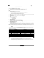
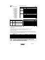
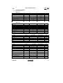
NG5-7-9 CAN Bus Interface
English
ATTENTION: To reduce the risk of electric
shock, do not remove cover. Refer servicing to
qualified service personnel. Disconnect the mains
supply before connecting or disconnecting the
links to the battery.
Read the Instruction Manual carefully before use.
Verify that the selected charge curve is suitable
for the type of battery You have to re-charge.
Explanation of Graphical Symbols:
The lightning flash with arrowhead symbol, within an equilateral triangle, is intended to alert the user to the presence
of uninsulated "dangerous voltage" within the equipment's enclosure; that may be of sufficient magnitude to constitute
a risk of electric shock to persons.
The exclamation point within an equilateral triangle is intended to alert the user to the presence of important operating
and maintenance (servicing) instructions in the literature accompanying the equipment.
This product is covered by warranty.
The relative warranty certificate is attached to the Instructions Manual.
If the Manual is not provided with this certificate, please ask your retailer for a copy.
For further references, please write the serial number in the proper space:
Serial No.
Information contained in this Manual relates to ZIVAN S.r.l. property which reserves the right to supply for the exclusive use of customers.
No other use is allowed without a written authorization supplied by ZIVAN S.r.l.
______________________________________________________________________________________________________
|ZIVAN S.r.l. will be not responsible for inaccuracies contained in this manual due to print or translation errors. ZIVAN S.r.l. has the right to
make changes or improvements, also for the user interest, without prejudicing the essential characteristic of operation and safety. ____________
Installation and safety instructions
Battery charger NG5-7-9 plus has been designed to provide safety and reliable. It is necessary to observe the following precautions in order to
avoid damage to persons and to the battery charger:
•
Read the installation instructions contained in this Manual carefully. For further information put the Manual in a proper place.
•
Fix the battery charger to a stable surface through the appropriate holes inserted on the fixing flanges. In case of installation on a
vehicle it is advisable to use anti-vibration supports.
•
Preferably the charger should be installed in the vertical position with the fan facing up. The horizontal installation is allowed. Never
install in the vertical position with the fan facing down.
•
Ensure all ventilation ports are not obstructed, to avoid the overheating. Do not put the battery charger near heat sources. Make sure
that free space around the battery charger is sufficient to provide adequate ventilation and an easy access to cables sockets.
•
Protect the battery charger from ingress of water. Do not pour liquids inside the case.
•
Verify that the available supply voltage corresponds to the voltage that is stated on the battery charger name plate. In case of doubt,
consult a retailer or local Electric Supply Authority.
•
As protection device in the input of the battery charger You can both use a switch of AC class, but it is warmly recommended to use
one of A class or even better one of B class.
•
For safety and electromagnetic compatibility, the battery charger has a 3-prong plug as a safety feature, and it will only fit into an
earthed outlet. If you can´t plug it in, chances are you have an older, non-earthed outlet; contact an electrician to have the outlet
replaced. Do not use an adapter to defeat the grounding.
•
To avoid damaging the power cord, do not put anything on it or place it where it will be walked on. If the cord becomes damaged or
frayed, replace it immediately.
•
If you are using an extension cord or power strip, make sure that the total of the amperes required by all the equipment on the
extension is less than the extension's rating.
•
Disconnect the mains supply (turn off the switch) before connecting or disconnecting the links to the battery.
•
To recharge Lead Acid batteries: WARNING: Explosive Gas - Avoid flames and sparks. The battery must be positioned in a correctly
cooled place.
•
Do not use to charge batteries installed on board of thermal engine cars. '
•
Avoid recharging of non-rechargeable batteries.
•
Verify that the nominal voltage of the battery to be re-charged corresponds to the voltage stated on the battery charger name plate.
•
Verify that the selected charging curve is suitable for the type of battery to be re-charged, in case of doubt, consult Your retailer. ZIVAN
S.r.l. will not accept any responsibility in case of mistaken choice of the charging curve that may cause irreversible damage to the
battery.
•
In order to avoid voltage drop, thereby assuring 100% charge at the battery, the output cables must be as short as possible, and the
diameter must be adequate for the output current.
•
Do not try to service the battery charger yourself. Opening the cover may expose you to shocks or other hazards.
•
If the battery charger does not work correctly or if it has been damaged, unplugged it immediately from the supply socket and from the
battery socket and contact a retailer.
D01570-02
9
NG5-7-9 CAN Bus Interface
Visualization
Digital Instrument
During the first minute after starting, on the digital instrument it will be displayed the value of the voltage drop on the output cables.
cable
To set the compensation value made by the charger to balance the voltage drop on the cables please follow the procedure
"Compensation
ation setting of the voltage drop on output cables.
After one minute from the starting the digital instrument will display the string of the
following parameters:
•
•
•
•
•
BATTERY VOLTAGE (two-tone red upper led).
CURRENT provided by the charger (two-tone red lower led).
TIME in hours lacking to the end of charge (two-tone
tone green upper led).
Ah supplied (two-tone green lower led).
CONNECTED GADGETS (no two-tone led on - only on a MASTER battery charge).
By pressing once the MODE button, the parameters' sequence is blocked and it will be kept the
last value displayed. By pressing again on the MODE button the sequence of parameters
restarts.
Compensation setting of the voltage drop on output cables.
During the lapse of time along which the digital instrument displays
displays the voltage drop on the output cables (first minute after starting)
it is
recommended to follow the below-mentioned
below
procedure:
v
1.
Gauge the voltage drop at the ends of the output bars of the battery charger (close to the cover).
2.
Gauge the voltage on the battery poles.
3.
Make the difference between the two values to get the voltage drop compensate.
4.
Press shortly the MODE button (ROLL) until reaching the nearest voltage value to the desired one: it is possible to ROLL
parameters
between 0,0V e 1,5V with steps of 0,1V.
5.
Press long the MODE button (ENTER) to confirm.
confirm
Ready Light
Charging status and current pha
PHASE
Phase 1
Phase 2
Phase 3
Phase 4
Phase5-Phase6
Phase6
End of charge
RED LED
On
On with short flashing
On
On with short flashing spegnimenti
Off
Off
GREEN LED
Off
Off
On with short flashing
On with short flashing
On with short flashing
On
When using the remote visualisation through two-tone
two
LED (AUX F - Pin 1 e 2), the following signals are valid:
PHASE
RED
GREEN
Phase 1
On
Off
Phase 2
On with short quenching
Off
Phase 3
Off
Off
Phases 4-5-6
6 & End charge
Off
On
S/S or alarm
Off
Off
IMPORTANT: according to the charging curve used maybe some phases are lacking.
YELLOW
Off
Off
On
Off
Off
D01570-02
10
NG5-7-9 CAN Bus Interface
Charging curve selection
You can press the MODE button according two modalities:
1.
Long pressure (at least 1 second): along the battery charger setting it means
ENTER
2.
Short pressure (less than 1 second): along the battery charger setting it means ROLL
Setting:
1.
2.
While pressing the MODE button light on the equipment.
ROLL: select the branch type:
•
•
•
3.
0 corresponds to a MASTER unit charger (connected with one or more SLAVES units).
from 1 to 8 it gives the ID of the SLAVE (used together to a MASTER).
9 identifies a STAND-ALONE charger (used as a single unit).
ENTER: branch type confirmation. Next selection is choose the Battery type (Lead acid type corresponds to BA1 otherwise
Gel
corresponds to BA2).
ENTER: Battery type confirmation: next level is to select the Charging curve.
ROLL: select the desired Charging
curve.
Availability is on 4 charging curves:
a.
CU1: lUla curve;
b.
CU2: IUIU0 curve;
c.
CU3: power supply;
d.
CU4: programmable curve (eg. desulphation).
ENTER: Charging curve confirmation: now select the Capacity.
ROLL: Capacity selection.
Starting point is a nominal value and by the ROLL you can select a value included between 50% and 140% of the nominal in
steps of 10%. On the display it is shown the last capacity selected.
ENTER: Capacity confirmation: then you can select the Recharging time (in hours).
ROLL: Recharging time confirmed .
Starting from a suggested Recharging time (according to the capacity chosen at the previous step) this time can only be
increased up to 20 hours max.
ENTER: Recharging time confirmation: the battery charger goes to a stand-by modality waiting that the output cables being
connected to the battery binding-clamps (if connections have been done already before starting the setting, once arrived at
point 10 the charger immediately starts).
4.
5.
6.
7.
8.
9.
10.
Warning: if some trouble or mistake may occur along setting procedure, switch off the battery charger by the rotary ON-OFF switch,
then switch oh again by keeping pressed the MODE button and restart setting operation from the beginning.
Alarms
When an alarm situation stopping the charge occurs, the display shows one of the information below according failure detected:
<A> <alarm code identified with a 2 digits
code> Alarm table list here following:
ALARM TYPE
LOGIC FAILURE #1
CAN BUS KO
WATCHDOG
HIGH TEMPERATURE BATTERY
MISSING PHASE
OVERCURRENT
HIGH TEMPERATURE
MISMATCH VOLTAGE
TIMEOUT
OVER DISCHARGE
DEEP DISCHARGE
BATTERY DISCONNECTED
PUMP MISTAKE
TH. SENSOR KO
CODE
A01
A02
A03
A05
A06
A07
A08
A09
A10
A11
A12
A13
A14
A15
Notes:
A05:
A11:
A12:
A15:
DESCRIPTION
Trouble on current detection
Trouble on CAN communication
Loqic board mis-workinq
Battery over temperature (>55°C)
Phase lacking
Over current
Battery charter high temperature
Internal failure
End of Phase 1 due to timeout
Over discharged Battery
Deeply discharged Battery
Battery disconnection white charging
. Air pump mis-working
Thermal sensor failure
STOP
YES
NO
YES
YES
YES
YES
YES
YES
YES
NO
NO
YES
NO
NO
The charge restarts once the battery temperature reaches a value lower than 50 °C.
Notice on the battery status. By pressing the MODE button, a desulphation phase start followed then by the standard charge.
Notice on the battery status. The standard charge is starting anyway
With the thermal sensor out of order the battery charger behaves as if it was not equipped with by showing the A15 code on the display.
Each alarm except A02 and A13, gives also a 30' lasting audible alarm.
D01570-02
11
NG5-7-9 CAN Bus Interface
English
Auxiliary contacts
Connector
C
D
E
F
Section
Function
AUX1
Mains
Presence
AUX2
End of
charge or
Trickle
Phase
Description (Unless otherwise
stated)the equipment is switched
When
on, the contact Normally Open
(NO) CLOSES and instead the
contact Normally Closed (NC)
OPENS.
When the Stop Phase or the No
Stop Phase is reached, the contact
Normally Open (NO) CLOSES and
instead the contact Normally
Closed (NC) OPENS.
PinN0
1-2
1
2
3
4
1
2
3
4
5
6
1
2
3
4
5
6
7
8
Description
Start/Stop Hardware
-BATT.
Thermal sensor contact
Temperature sensor
Temperature sensor (- BATT)
Air Pump contact
-BATT
Air Pump sensor
NC normally closed (AUX 1)
NO normally open (AUX 1)
COM common (AUX 1)
LED R (remote visualisation)
LED V (remote visualisation)
-BATT
-BATT
NC normally closed
COM common2)
NC normally open
Further contact for digital input
Nominal current/Max instant current A
10/15
Nominal voltage/ Max voltage commutable Vac
250/250
Nominal load in AC1 VA
2500
Nominal load in AC15 (230Vac) VA
500
Single phase engine capacity (230 Vac) Kw
0.37
Break power in DC1:30/110/220 VA
10/0.3/0.12
Minimum mW commutable charge (V/mA)
500 (5/100)
Mechanical length AC/DC cycles
-/10x106
Electrical duration with nominal charge in A1 cycles
100X103
Isolation according EN 61810-1 2nd edition
2.5 kV/2
Isolation between coil and contacts (1.2/50 us) kV
4
Dielectric rigidness between open contacts Vac
1000
ADDITIONAL FEATURES WITH AIR PUMP
Standard Version
The Air Pump technology generates a re-mix of the acid inside the battery by a constant delivery of air pumping.
The battery charger controls the air pump by an auxiliary contact (generally AUX1).
An air injection cycle along all the charging period is held as per requirements of the battery specifications.
Pressure sensor version
Further to the characteristics of the standard version it is also available an electronic circuit equipped with an air pressure sensor. At
the beginning of the charging process, the sensor verifies that the pressure in the circuit is included in a definite window between a
minimum and a maximum value (look at the following table). When an anomaly occurs the battery charger will modify the charging
factor by effecting a charge without detecting and controlling the Air Pump
Technical Features
Description
Symbol
Power absorbed by the Air Pump
PaD
input fuse
Maximal dimensions
axbxc
Weight
.
Air Delivery*
Q
Available pressure range
Ap
* To know the effective air delivery please refer to the plate
12
Test Condition
Air Pump controlled
Equipment interns
Without connecting cables
Without connectinq cables
Air Pump controlled
Starting charging point
Value and/or Range
90
1,6
657x267x226
17,5
4:13
50 : 250
D01570-02
Unit
W
A
mm
kg
l/min
mbar
English
NG5-7-9 CAN Bus Interface
TECHNICAL FEATURES
Ta =25°C unless otherwise specified
Mains side
Description
Supply Voltaqe Three-phase
Frequency
Symbol
Vin
f
Test Condition
lfmax
P = Pmax
Inrush Current
Power Factor
Absorbed Minimum Power
COS phi
Pinmin
Vin=400Veff
P = Pmax
End of charge
Absorbed Maximum Power
Pinmax
P = Pmax
Absorbed Maximum Current per phase
Value and/or Range
400 + 15%
50 + 60
10(NG5)
14(NG7)
18(NG9)
<2,35
0,72
<10
5 (NG5) 7
(NG7) 9( NG9)
Unit
Veff
Hz
Aeff
A
W
kW
* Maximum value per model. For the effective current absorption please refer to the charger´s identification label.
Battery side
Description
Output current
Maximum output current
Output current ripple
Absorbed current
Output voltage
Constant output voltage
Thermal compensation of output voltaqe
Operating range of Temperature Sensor
Output voltaqe ripple
Maximum power supplied
Output capacity
Symbol
I
I1
>a
U
U1
dU1/dT AT
p
max
Test Condition
Phase 2
Value and/or Range
See curve
See curve
< 5%
<0,5
See curve
See curve
Phase 2
-5 from -20 to +50
U-U1
<1%
4800 (NG5) 6300
(NG7) 7700 (NG9)
Depend on the model (>0,2)
mF
Phase 1
l = I1
Equipment turned off
U = U1,I=I1
C
-
Unit
A
mA
V
mV/CC-cell)
<C
W
General
Description
Operating range of temperature
Maximum relative humidity
Switching frequency
Efficiency
Maximum size
Weight
Enclosure class
Symbol
Test Condition
Value and/or Range
Unit
AT
RH
fc
eta
axbxc
At each operation condition
Without connectinq cable
from -20 to +50
90%
20 ±5%
> 87%
550x270x120
9
IP20
°C
kHz
mm
kg
Protection and Safety
Description
Symbol
Value and/or Range
Unit
Mains to Battery side
1250
VAC
Insulation
Mains side to Earth
500
VDC
Insulation
Battery side to Earth
500
VDC
'L
Supplied equipment
mA
F1-F2-F3
Inside the equipment
F5
Inside the equipment
<7
20 (NG5) 20
(NG7) 25 (NG9)
about 1,2xI1
-
Equipment turn on
1,5
V/cell
Urn
Phase 3 (lUla - lUIUo)
At the connection to the
Battery
See curve
Protection provided by fuse
F5
V
Ta=55<C
100
Insulation
Leakage current (EMC Filter)
Input fuses
Output fuse
Minimum output voltage of operation (Battery
Detector)
Maximum output voltage
Reverse output polarity
Thermal protection of semiconductors
(Temperature of Thermal Alarm)
Safety Requirements (Rules)
EMC Requirements (Rules)
D01570-02
Test Condition
A
A
EN60335-1,EN60335-2-29
EN55011, EN61000-4-2,
EN61000-4-4
13